Note: Descriptions are shown in the official language in which they were submitted.
CA 03135229 2021-09-28
WO 2020/200541 PCT/EP2020/052338
1
A method for inspection of catenary anchor lines connected to a floating
object.
Field of the invention
The present invention relates to a method for measuring a line angle of a
mooring line connected to a floating object. Also, the invention relates to a
system for
measuring a line angle of a mooring line connected to a floating object.
Background
There is a worldwide trend in the offshore industry to minimize diver
intervention
to reduce the associated risks of this kind of operation. At the same time,
progress in
automated control system have allowed the deployment of sophisticated vehicles
in
difficult environments.
For a floating object such as a buoy that is moored at sea by mooring lines, a
periodic inspection of the submerged part of the floating object is required
to check the
state of the mooring lines and to avoid unexpected failure thereof. Mooring
lines
comprise lines made from synthetic material such as nylon and polyester,
and/or steel
wire or combinations thereof. Also a mooring line may consist of a mooring
chain
consisting of steel links or may comprise at least a segment of such a mooring
chain.
One of the measures that need to be performed during the periodic inspection
of
the terminal is that of the line angles formed by the mooring lines with the
vertical
direction in close proximity of the buoy and of its mooring line connectors.
In particular for catenary anchor leg based mooring, i.e., for CALM terminals,
where the buoy responds to even moderate sea states with a considerable
amplitude
of motions and speeds, the approach to the buoy by a diver or a remotely
operated
device (ROV) can be difficult. For example, a wave height of about one metre,
can
cause motion excursions of several meters for the terminal.
It is an object of the present invention to provide a method for measuring a
line
angle of the mooring line near the buoy, with adequate precision, but without
divers or
ROV and without directly approaching the buoy, thus avoiding a collision risk
associated to large motions of the buoy.
Summary of the invention
The object is achieved by a method for measuring a line angle of at least one
mooring line connected to a floating object, the floating object floating in a
body of
water, the mooring line being connected between the floating object and an
anchoring
CA 03135229 2021-09-28
WO 2020/200541 PCT/EP2020/052338
2
body disposed in a bed of the body of water, in which the floating object is
coupled to
the mooring line by a line connector; the method comprising:
= defining at least three data points each associated with a respective
location on the
mooring line; = on said at least three data points obtaining a respective
value
associated with the location on the mooring line; = determining parameters of
an
equation describing an anchor line curve from the obtained values associated
with the
location on the mooring line for said at least three data points; =
calculating at a
predetermined position on the mooring line a line angle of the mooring line
from a
derivative of the equation of the anchor line curve at the predetermined
position based
on the determined parameters, wherein the method further comprises:
= providing a group of sensors, comprising at least three sensors, each of
the sensors
configured for measuring the respective value associated with the mooring
line;
= on each of the at least three data points installing an associated sensor
on the
mooring line from the group of sensors, the sensors each being configured for
measuring a the respective value associated with the mooring line and for
transmitting
a signal of said measured value, wherein at least a second sensor and a third
sensor
are installed on predetermined locations on the mooring line by a remotely
operated
underwater vehicle, ROV, and the step of obtaining the values on the at least
three
data points comprises receiving from each associated sensor the signal of the
respective measured value, and associating for each received signal the
measured
value with the location of the data point on the mooring line.
The method allows to measure the anchor line curve from either positions of at
least three points or positions at a first and a second point plus a local
line angle of the
anchor line curve at a third point, and determine the line angle without the
need to
perform a measurement in the submerged zone adjacent to the buoy by a diver or
ROV.
The invention also relates to a system for measuring a line angle of a mooring
line connected to a floating object, in accordance with claim 14. Moreover,
the present
invention relates to a floating object provided with a system for measuring a
line angle
of a mooring line connected to the floating object.
Brief description of drawings
Embodiments of the present invention will be described hereinafter, by way of
example only, with reference to the accompanying drawings which are schematic
in
nature and therefore not necessarily drawn to scale. In the drawings,
identical or
similar elements are indicated by the same reference sign.
CA 03135229 2021-09-28
WO 2020/200541 PCT/EP2020/052338
3
Figure 1 schematically shows a floating object moored in a body of water
illustrating an embodiment of the invention;
Figure 2 schematically shows a portion of Figure 1 in more detail,
and
Figure 3 shows a flow diagram of a method in accordance with an embodiment of
the
invention.
Description of embodiments
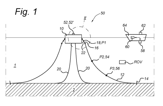
Figure 1 schematically shows a floating object moored in a body of water
illustrating an embodiment of the invention.
In a body of water 1 such as a sea or lake, a floating object 10 is moored by
means of mooring lines 12 to anchoring bodies 14. Each anchoring body 14 is
disposed on or in the sea bed 2 or lake bed 2.
Each mooring line 12 is connected to the floating object 10 by means of a line
connector 16, that comprises an articulation 18 to allow a line angle 22
between the
mooring line and the vertical (i.e., a mooring line angle) to change depending
on forces
exerted on the floating object, such as low-tide, high-tide, currents and
storm.
Further, some risers 20 for transporting hydrocarbon liquid and/or gas may be
running between well heads (not shown) on the sea bed 2 and the floating
object 10.
To allow measurement of the line angle, a system 50 is provided for
determining
the line angle 22 at the articulation 18 from the shape of the mooring line 12
between
the floating object 10 and the anchoring body 14. Here such a shape is
referred to as
an anchor line curve.
To determine the anchor line curve shape, it is considered to measure a
geographical location (hereafter: geolocation) of at least three points P1,
P2, P3 on the
anchor line curve or a geolocation of two points P1, P2 plus a locally
measured line
angle at a third point P3 on the anchor line curve. Using the respective three
geolocations (or the two geolocations plus a local line angle) of these at
least one 3
points P1, P2, P3 a curve fitting procedure is performed to obtain a set of
parameters
describing the anchor line curve as function of the geolocation. From the set
of
parameters, a derivative of the anchor line curve can be calculated at the
geolocation
of the articulation 18, which is a predetermined location on the mooring line.
From the
derivative of the anchor line curve at the geolocation of the articulation 18,
the line
angle 22 at the articulation with the vertical is then established.
In case the geolocation of two points plus the locally measured line angle at
the
third point are measured, the locally measured line angle at the third point
may be
CA 03135229 2021-09-28
WO 2020/200541 PCT/EP2020/052338
4
measured at a same location as the geolocation of the second point. The
locations of
the second and third points may coincide in that case.
The system comprises at least first, second and third position sensors 52, 54,
56, that are to be installed on the mooring line to be measured.
Further, the system comprises a first device 58 for receiving from each
position
sensor 52, 54, 56 the respective position signal and a second device 60 for
determining from each received position signal the location of the respective
position
sensor, the location of the point on the mooring line associated with the
respective
position sensor.
In an embodiment, each of the at least first, second and third position
sensors
52, 54, 56 is a transponder that is configured to transmit a signal relating
to the
respective location thereof. The first device 58 is a transceiver that is
configured to
transmit signals to the position sensors to initiate the transmission of the
location
related signals from the transponders, and to receive the location related
signals from
the transponders.
Depending on the transponder or sensor type, the location related signals can
comprise data of either absolute locations or relative locations. The absolute
locations
can comprise geographical coordinates. The relative locations can comprise
locations
relative to the location of the first device 58.
In a further embodiment, the first position sensor 52 is based on a first GPS
sensor which is configured to produce first position sensor geolocation
coordinates.
The first GPS sensor is installed on the floating object 10. Using the first
position
sensor geolocation coordinates from the first GPS sensor 52 a location of the
centre of
the articulation 18 of the line connector 16 is determined as the geolocation
of the first
point Pl. This will be explained in more detail with reference to Figure 2,
below. The
signals of the first GPS sensor 52 are received by a suitable receiver (not
shown) and
transferred to the second device 60 as geolocation of the floating object 10.
In a preferred embodiment, the first position sensor 52 is the first GPS
sensor
and the second and third position sensors 54, 56 are USBL (ultra-short
baseline)
transponders installed at a location of the second point and third point
respectively.
According to a method of the invention, a remotely operated underwater vehicle
(ROV) is used to install them on the mooring line. Advantageously, the use of
the ROV
allows diver-less deployment of the underwater position sensors 54, 56
The location of the second point and third point are obtained by the USBL
transceiver 58 from the readings of the USBL transponders 54, 56. Typically,
the
CA 03135229 2021-09-28
WO 2020/200541 PCT/EP2020/052338
transceiver 58 and second device 60 are deployed on a support vessel 64,
positioned
at some distance from the floating object.
In case the USBL transceiver 58 is associated with a second GPS sensor 62, the
locations of the second point and third point can be referenced to absolute
locations
5 .. (geolocations) of the second point and third point P2, P3 through the GPS
coordinates
of the second GPS sensor 62 associated with the USBL transceiver 58. The
second
GPS sensor 62 is typically close to the USBL transceiver 58, on the support
vessel 64.
In this manner, the location of the USBL transceiver can be determined from a
GPS
location by the second GPS sensor associated with the USBL transceiver.
The second device 60 is a computational device capable of executing a first
computational procedure for determining parameter values of an equation
describing
an anchor line curve passing through the respective locations of said at least
three
points P1, P2, P3, obtained as described above, and may be based on any
suitable
numerical curve fitting method.
Alternatively, the first computational procedure may comprise determining
parameter values of an equation describing an anchor line curve passing
through the
respective locations of two points P1, P2, plus taking into account a locally
measured
line angle at a third point P3 (which third point may coincide with the second
point).
Additionally, the second device 60 is capable of executing a second
computational procedure for calculating at a predetermined position on the
mooring
line a line angle 22 with the vertical direction from a derivative of the
equation of the
anchor line curve based on the determined parameter values.
An embodiment of the first and second computational procedures will be
described in more detail with reference to Figure 3.
The skilled person will appreciate that the second device 60 can be a single
computational device, or a number of computational devices arranged in a
network,
arranged for carrying out the computational procedures. The second device 60
is
connected to the first device 58 for data-communication by a network (not
shown),
either wired or wireless, and may be located at a same location as the first
device 58,
but could be located at a different location.
According to the invention, the line angle 22 at the articulation is
determined
from parameters describing the anchor line curve shape by using computation
involving the derivative of the anchor line curve at the location of the
articulation 18 of
the line connector 16.
Figure 2 schematically shows a part of Figure 1 in more detail.
CA 03135229 2021-09-28
WO 2020/200541 PCT/EP2020/052338
6
In case the first position sensor 52 on the floating object 10 is a first GPS
sensor
as described above, the centre of the articulation 18 of the line connector 16
is taken
as the geolocation of the first point. The geolocation of the first point is
then calculated
from the geolocation of the first GPS sensor on the floating object 10 with a
correction
for the distance between a location L2 of the first GPS sensor on the floating
object
and a location L1 of the centre of the articulation 18. The correction can be
determined
from the actual layout of the floating object construction and a position of
the centre of
the articulation 18 of the line connector 16 at the floating object 10,
corresponding to a
distance vector denoted X (indicated by dashed line) between the centre of the
articulation 18 and the actual position of the first GPS sensor 52 on the
floating object
10, i.e., between location L2 and location L1.
In an embodiment, the correction is performed by the second device 60.
Figure 3 shows a flow diagram of a method in accordance with an embodiment
of the invention.
According to an embodiment of the invention, a method is provided for carrying
out a procedure 300 to determine a line angle value 22 for the floating object
10
moored by the mooring line 12.
In a first step 310, the method comprises the installation of the first GPS
sensor
as the first sensor on the floating object and at least the second and third
sensors on
the mooring line. Also this step comprises the deployment of a measurement
facility 64
comprising at least the first device 58 at some distance from the floating
object and
mooring line. The second device 60 may be located at the measurement facility
64
near the first device 58, but alternatively could be located at a different
location.
In a subsequent step 320, the method comprises the step of receiving by the
first
computational device 58, location related signals from the first position
sensor and at
least one of the second and third sensors.
Additionally, the first position sensor can be equipped with an attitude
sensor to
measure local attitude or local line angle related signal in combination with
the position
signal.
In an alternative embodiment, location related signals are received from the
second position sensor and local line angle related signals are received from
the third
sensor.
In a next step, the second device 60 is arranged to carry out a procedure 330
to
determine the location of each of the first position sensor and at least the
second and
third sensor on the mooring line 12. The determined locations can be either
relative
CA 03135229 2021-09-28
WO 2020/200541 PCT/EP2020/052338
7
locations, with relative positions with respect to the location of the
measurement facility
or absolute locations for example defined as geolocations.
In a subsequent step, the second computation device 60 is arranged to carry
out
a procedure 340 to determine the location of the first point at the centre of
the
articulation 18 of the line connector 16 from the location of the first
position sensor and
the distance vector X.
In a next step, the second device 60 is arranged to carry out a procedure 350
to
determine parameter values that describe the anchor line curve shape as a
function of
the location of the at least three points on the mooring line 12 (or the
location of two
points on the mooring line plus a local line angle at a point on the mooring
line). The
procedure 350 may use a curve fitting method to obtain the parameter values.
In a further step, the second device 60 is arranged to carry out a procedure
360
to determine a line angle value at the location of the centre of the
articulation 18 of the
line connector 16, by calculating the local derivative at the latter location.
Optionally, the line angle value can be determined repeatedly over time to
obtain
a time-average of the line angle value (and/or any one of the values of the
curve fitting
parameters, the locations of the at least three points and/or the locations of
the at least
three position sensors), by repeating the procedural steps 320 ¨ 360, as
described
above.
In a further embodiment, the method comprises in a step 380 that real-time
values or time-averaged values of the line angle, and/or the curve fitting
parameters,
and/or the locations of the at least three points and/or the locations of the
at least three
position sensors are stored in a computer readable medium.
Such a method may comprise storing a value of at least the calculated line
angle
with either the vertical or the horizontal direction in a computer readable
medium,
and/or storing a value of the measured positions for the at least three data
points on
the mooring line in a computer readable medium, and/or storing a value of
measured
position signals from the at least three position sensors in a computer
readable
medium, and/or storing a value of determined parameters of the equation
describing
the anchor line curve from the measured values associated with the location on
the
mooring line for said at least three data points.
The stored data values can be used for example for on-line or off-line
analysis,
but also in relation to process monitoring or process control when a vessel
(not shown)
is moored at the floating object 10 for offloading liquid or gaseous
hydrocarbons from
the risers 20.
CA 03135229 2021-09-28
WO 2020/200541
PCT/EP2020/052338
8
In an embodiment, the mooring buoy arrangement is used in a water depth of
about 2000 m or less.
Figure 4 schematically shows a floating object moored in a body of water
illustrating an embodiment of the invention.
In Figure 4 entities with the same reference number as shown in Figure(s) 1-3
refer to corresponding entities.
According to an embodiment of the invention, a method is provided for
measuring the chain angle which comprises indirectly measuring a top angle of
at
least one mooring chain connected to a floating object 10 via a 3D bathymetry
system
71 attached to an unmanned surface vehicle 70. The top angle is determined by
fitting
of the catenary line to bathymetry reflection points together with a 3D
surface fit.
The method comprises:
navigating around the floating object with the unmanned surface vehicle
70 (a fully remotely operated survey vehicle) while acquiring a 3D point cloud
representative of the subsea layout mapping underneath the floating terminal.
The 3D bathymetry system 71, attached to the unmanned surface vehicle 70,
emits acoustic waves towards the seabed and every time the acoustic waves come
across a subsea structure, there is a reflection of the acoustic waves back to
the
bathymetry system. The amount of time it takes for the acoustic waves to
bounce off
structures on the seabed 2 and return to (a receiver of) the 3D bathymetry
system is
used to determine exact coordinates and depth of each reflection point,
creating an
accurate field layout mapping of all underwater structures underneath the
floating
object.
post processing the respective 3D point cloud using advanced data
analytics tools by interpolating a best-fitting 3D surface among the
reflection points
that represent the catenary line (for example by parametrizing a catenary line
equation
using nonlinear least-squares regression analysis) for one or more of the
mooring lines
12 while computing best confidence, prediction and calibration intervals using
well-
known statistical tools.
iii. calculating a top inclination (top angle) value of each measured
mooring
line with (predetermined) adequate precision and accuracy from a derivative of
the
equation of the anchor line curve at a predetermined position.
The foregoing description details certain embodiments of the invention. It
will
be appreciated, however, that no matter how detailed the foregoing appears in
text,
the invention may be practiced in various ways.
CA 03135229 2021-09-28
WO 2020/200541
PCT/EP2020/052338
9
While the above detailed description has shown, described, and pointed out
novel features of the invention as applied to various embodiments, it will be
understood that various modifications in the form and details of the system or
method
illustrated may be made by those skilled in the art without departing from the
spirit of
the invention. The scope of the invention is indicated by the appended claims
rather
than by the foregoing description. All modifications that come within the
meaning and
range of equivalency of the claims are to be embraced within their scope.