Note: Descriptions are shown in the official language in which they were submitted.
CA 03135401 2021-09-28
WO 2020/206312 PCT/US2020/026655
LUGGAGE SYSTEM
CROSS-REFERENCE TO RELATED APPLICATIONS
[0001] The present application claims priority to U.S. Patent Application No.
16/839,311 filed
on April 3, 2020, U.S. Patent Application No. 16/735,013 filed on January 6,
2020, and
U.S. Provisional Application No. 62/830,203 filed on April 5, 2019. U.S.
Patent
Application No. 16/839,311 is a continuation-in-part of U.S. Patent
Application No.
16/735,013 filed on January 6, 2020, which claims priority to U.S. Provisional
Patent
Application No. 62/788,886 filed on January 6, 2019 and U.S. Provisional
Patent
Application No. 62/788,888 filed on January 6, 2019. U.S. Patent Application
No.
16/839,311 also claims priority to U.S. Provisional Patent Application No.
62/830,203
filed on April 5, 2019. All of the above referenced applications are
incorporated by
reference in their entirety.
FIELD OF INVENTION
[0002] This disclosure relates to luggage and luggage systems.
BACKGROUND
[0003] Suitcases may be used for transporting clothing, footwear, and other
materials or items.
However, the demands of travel can sometimes cause damage to the suitcase of
damage
to their contents. Either traveling by airplane or traveling by automobile, a
durable and
waterproof suitcase may be needed to protect the contents within a suitcase.
For ease
of movement, a trolley handle gives a user a simple means to pull or push a
wheeled
suitcase.
BRIEF SUMMARY
[0004] Aspects of this disclosure may relate to a suitcase having a base
including: a first shell
structure having a first side and a second side opposite the first side, where
the first
shell structure has a first end and a second end opposite the first side and
where the first
side has a first outward facing surface and a second outward facing surface.
The second
outward facing surface may be offset a first fixed distance from the first
outward facing
surface. The first shell structure may have a bottom portion connected to a
first end of
the first shell structure and configured to support the suitcase on a surface.
A first
1
CA 03135401 2021-09-28
WO 2020/206312 PCT/US2020/026655
interior void may be defined by the first shell structure and the bottom
portion, and a
lower latch recess may be located in the second outward facing surface, where
the lower
latch recess includes a rear surface, a lower surface, and a pair of side
surfaces. The
suitcase may also include a lid rotatably connected to the base, where the lid
includes:
a second shell structure having a third side and a fourth side opposite the
third side,
where the second shell structure includes a third end and a fourth end
opposite the third
end. The third side may have a third outward facing surface and a fourth
outward facing
surface, where the fourth outward facing surface may be offset a second fixed
distance
from the third outward facing surface. The second shell structure may also
include a
top portion connected to a third end of the second shell structure. A second
interior
void may be defined by the second shell structure and the top portion; and an
upper
latch recess located in the second outward facing surface. A latch assembly
may be
located within the lower latch recess and the upper latch recess, where the
lower latch
recess and the upper latch recess have a depth that is greater than a
thickness of the
latch assembly. Additionally, when the suitcase is in a closed configuration,
a perimeter
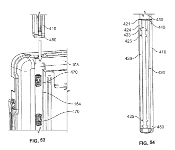
of the latch assembly is located within a combined perimeter of the upper
latch recess
and lower latch recess. The lid may be free of openings that extend through
the first
outward facing surface into the second interior void. The second outward
facing surface
may extend along an entire perimeter of the base. The fourth outward facing
surface
may also extend along an entire perimeter of the lid. The lid is rotatably
connected to
the base by at least one hinge. A portion of the at least one hinge may be
located in an
upper hinge recess and a lower hinge recess, where the lower hinge recess is
located in
the second outward facing surface and the upper hinge recess is located in the
fourth
outward facing surface.
[0005] Still other aspects of this disclosure may relate to a suitcase with a
lid connected to a
base by at least one hinge, where the at least one hinge comprises at least
two linkages,
and when the suitcase is in an open configuration, the at least one hinge
defines a
rotational axis and the rotational axis is located outside of a rear edge of
the base and a
rear edge of the lid. The base may include a pair of wheel assemblies, where
each
wheel assembly is attached into a wheel recess formed in the base, and where
each
wheel assembly includes a wheel housing and a wheel. Each housing may include
an
outward facing flange surface that is spaced outward a fixed distance from
adjacent
surfaces of the base around the wheel recess. The bottom portion of the base
may also
2
CA 03135401 2021-09-28
WO 2020/206312 PCT/US2020/026655
include a tapered region located between the pair of wheel assemblies, where
the
tapered region forms an angle within a range of 1 degree and 30 degrees when
measured
from a central portion of the bottom portion to a lower surface of the tapered
region.
The base may include a second end surface along the second end of the first
shell
structure, and the lid includes a fourth end surface along the fourth end of
the second
shell structure, and when the suitcase is in a closed configuration, the
second end
surface and the fourth end surface are spaced apart from each other. The
second end
surface may include a sealing rib that protrudes from the second end surface
and the
fourth end surface may include a channel that receives a gasket, and when the
suitcase
is in the closed configuration, the rib engages the gasket. The base may
include a
plurality of ribs that extend from a surface underneath the lower latch recess
to an
interior surface of the bottom portion, where each rib of the plurality of
ribs is spaced
apart from each other by a distance within a range of 8 to 10 times a
thickness of each
rib. A first volume of the first interior void may be within 10 percent of a
second
volume to the second interior void. Still additional aspects of this
disclosure may relate
to a suitcase having a base including: a first shell structure having a first
side and a
second side opposite the first side, where the shell structure has a first end
and a second
end opposite the first end and where the first side has a first outward facing
surface and
a second outward facing surface. The second outward facing surface may be
offset a
first fixed distance from the first outward facing surface. The first shell
structure may
also include a bottom portion connected to a first end of the first shell
structure. A first
interior void may be defined by the first shell structure and the bottom
portion; and a
lower hinge recess may be located in the second outward facing surface. A lid
may be
rotatably connected to the base, where the lid includes: a second shell
structure having
a third side and a fourth side opposite the third side, the shell structure
having a third
end and a fourth end opposite the third end. The third side may have a third
outward
facing surface and a fourth outward facing surface, where the fourth outward
facing
surface is offset a second fixed distance from the third outward facing
surface. The
second shell structure may have a top portion connected to the third end of
the shell
structure; and a second interior void may be defined by the second shell
structure and
the top portion. A hinge assembly may be at least partially received within
the lower
hinge recess, where the lid is rotatably connected to the base by the hinge
assembly.
The hinge assembly may include at least two linkages. When the suitcase is in
an open
configuration, the at least one hinge assembly may define a hinge axis where
the hinge
3
CA 03135401 2021-09-28
WO 2020/206312 PCT/US2020/026655
axis is located outside of a rear edge of the base and a rear edge of the lid.
The hinge
assembly may be at least partially received in an upper hinge recess, where
the upper
hinge recess is located within the fourth outward facing surface. In some
examples,
the hinge assembly includes three hinge assemblies. Each hinge assembly may
include
a base hinge insert and a lid hinge insert, where the base hinge insert and
the lid hinge
insert both include a cavity that at least partially receives the at least two
linkages. The
recess of the base hinge insert has a depth that is greater than a thickness
of the at least
two hinges. The at least two linkages may include a first linkage and a second
linkage,
where the first linkage includes a first linkage opening and a second linkage
pin. For
example, a first linkage pin may extend through the first linkage opening and
into the
base hinge insert, and where a second linkage pin extends through the second
linkage
opening and into the lid hinge insert.
[0006] Yet additional aspects of this disclosure may relate to a method for
forming a suitcase,
including: (a) molding a base shell, where the base shell has a plurality of
lower latch
recesses, a plurality of lower hinge recesses, a base shell structure, and a
base interior
void; (b) molding a lid shell, where the lid shell has a plurality of upper
latch recesses
and a plurality of upper hinge recesses, an lid shell structure, and a lid
interior void; (c)
placing the base shell and the lid shell adjacent each other, wherein the base
interior
void and the lid interior void are both facing the same direction and wherein
the lower
hinge recess and the upper hinge recess are facing towards each other; (d)
placing a first
portion of the hinge assembly into the lower hinge recess; (e) placing a
second portion
of the hinge assembly into the upper hinge recess; (f) securing the first
portion of the
hinge assembly to the base using a first mechanical fastener; (g) securing the
second
portion of the hinge assembly to the lid using a second mechanical fastener;
(h) placing
a latch assembly into the upper latch recess; and (i) securing the latch
assembly to the
lid using a third mechanical fastener, where the first mechanical fastener,
the second
mechanical fastener, and the third mechanical fastener are all oriented
generally parallel
to each other. The first mechanical fastener may be oriented generally
parallel to the
third side of the lid shell. The method may also include attaching the wheel
assembly
into a wheel recess on the base shell using a fourth mechanical fastener,
where the
fourth mechanical fastener is oriented generally parallel to the first
mechanical fastener.
In addition, the method may include attaching the portion of the latch
assembly to a lid
latch mount prior to placing the portion of the latch assembly into the upper
latch recess,
4
CA 03135401 2021-09-28
WO 2020/206312 PCT/US2020/026655
where the lid latch mount includes a body member and a flange, where the
flange
extends on outward from the body member and wherein the body member of the lid
latch mount is received within the upper latch recess. The method may also
include
securing the lid latch mount to the lid shell with the third mechanical
fastener that
extends through an opening in the flange and into a thickened portion of the
lid shell.
[0007] Other aspects of this disclosure may relate to a suitcase that has a
base that includes a
first shell structure having a first side and a second side opposite the first
side, where
the first shell structure having a first end and a second end opposite the
first end. A
bottom portion may be connected to the first end of the first shell structure
and
configured to support the suitcase on a surface. A first interior void may be
defined by
the first shell structure and the bottom portion, and a lower latch recess may
be located
within the second outward facing surface, where the lower latch recess has a
rear
surface, a lower surface, and a pair of side surfaces. A lid may be rotatably
connected
to the base, where the lid includes a second shell structure having a third
side and a
fourth side opposite the third side. The second shell structure may also have
a third end
and a fourth end, where a top portion is connected a top portion connected to
the third
end of the second shell structure; and a second interior void defined by the
second shell
structure and the top portion. An interior liner may be releasably secured to
either the
base shell within the first interior void or the lid within the second
interior void, where
the interior liner includes at least one storage cavity recessed from an upper
surface of
the liner and includes a liner attachment assembly that releasably engages a
base
attachment member. The liner attachment assembly may be permanently attached
to
the interior liner, and the base attachment member may be permanently attached
to an
interior surface of the suitcase. The liner attachment assembly may include a
grip
member that is rotated a predetermined amount to move the liner attachment
assembly
from an unlocked position to a locked position. When the liner attachment
assembly is
in the unlocked position, the liner is secured to the suitcase and when the
liner
attachment assembly is in the unlocked position, the liner is allowed to be
removed
from the suitcase.
[0008] Additional aspects may relate to a liner that is releasably secured to
a suitcase by a liner
attachment assembly, where the liner attachment assembly may include a tail
member,
a flange member, and the grip member, where the tail member includes a tail
body
CA 03135401 2021-09-28
WO 2020/206312 PCT/US2020/026655
member with a locking projection extending outwardly from the tail body
member. The
tail body member may have a generally cylindrical shape. In some examples, the
locking projection may comprise two locking projections that are arranged
opposite
each other and where each locking projection may include at least one tapered
surface.
The flange member may include a flange opening that receives a portion of the
tail
member, and where the grip member may attach to the portion of the tail member
that
extends into the flange opening. The liner attachment assembly may be moved to
the
locked position from the unlocked position by rotating the grip member
approximately
90 degrees in a first direction, and the liner attachment assembly is moved to
the
unlocked position from the locked position by rotating the grip member
approximately
90 degrees in a second direction, where the second direction is opposite the
first
direction. The base attachment member may include a first wall and a second
wall
where each wall extends away from the interior surface of the base with a
first end at
the interior surface and a second end opposite the first end. The first wall
may include
a first base locking projection located at the second end that extends toward
the second
wall and the second wall may include a second base locking projection located
at the
second end that extends toward the first wall. When the liner attachment
assembly is
in the locked position, the locking projection of the liner attachment
assembly is at least
partially positioned underneath the first base locking projection or the
second base
locking projection.
[0009] Another aspect of this disclosure may relate to a suitcase including a
first shell structure
having a first side and a second side opposite the first side, where the first
shell structure
has a first end and a second end opposite the first end and where the first
shell structure
has a first outward facing surface and a second outward facing surface. The
second
outward facing surface may be offset a first fixed distance from the first
outward facing
surface. The first shell structure may also include a bottom portion connected
to a first
end of the first shell structure. A first interior void may be defined by the
first shell
structure and the bottom portion; and a lower hinge recess may be located in
the second
outward facing surface. A lid may be rotatably connected to the base, where
the lid
includes: a second shell structure having a third side and a fourth side
opposite the third
side, the shell structure having a third end and a fourth end opposite the
third end. The
second shell structure may have a third outward facing surface and a fourth
outward
facing surface, where the fourth outward facing surface is offset a second
fixed distance
6
CA 03135401 2021-09-28
WO 2020/206312 PCT/US2020/026655
from the third outward facing surface. The second shell structure may have a
top
portion connected to a third end of the shell structure, and a second interior
void may
be defined by the second shell structure and the top portion. The suitcase may
include
an extendable trolley handle, where the trolley handle includes: (a) a pair of
nested
extrusion assemblies, where each extrusion assembly includes a major extrusion
and a
minor extrusion, and where the minor extrusion is nested within a central
opening of
the major extrusion, and slidably engaged with the major extrusion; and (b) a
grip
connected to the minor extrusion of each of the pair of extrusion assemblies,
where the
grip includes a release button. The grip may include a release button that
when pressed
actuates a rack and pinion gear assembly located within the grip to allow the
trolley
handle to extend. The rack and pinion gear assembly may include a pair of rack
gear
members, where each rack gear member includes an engaging member that contacts
a
portion of the release button, a rack gear portion. Each rack gear portion may
engage
a pinion gear to equalize movement of the rack gear members and where the
engaging
member has a first angled surface that engages the release button, where the
first angled
surface includes a compound angle relative to an upper surface of the base
member.
Each rack gear member may also include a transmitting member at an end
opposite the
rack gear member, where the transmitting member has a second angled surface
that
contacts a third angled surface on an activating member, where the activating
member
disengages a locking mechanism for the trolley handle assembly.
[0010] In addition, further aspects of this disclosure may relate to a
suitcase that includes an
extendable trolley handle assembly that includes: (a) a pair of extrusion
assemblies,
where each extrusion assembly includes a major extrusion and a minor
extrusion, where
the minor extrusion is nested within a central opening of the major extrusion,
and
slidably engaged with the major extrusion and (b) a grip portion connected to
the minor
extrusion of each of the pair of extrusion assemblies, where the extrusion
assembly is
at least partially secured to the base by a plurality of mounting clips that
are mounted
to an outward facing surface of the bottom portion of the base. The plurality
of
mounting clips may be secured within a recess along the bottom portion of the
base and
may also be evenly spaced apart within the recess. Each mounting clip may be
secured
within a pocket located within the recess. Additionally, each mounting clip of
the
plurality of mounting clips may include a central body with a top end, a
bottom end, a
front side, a rear side, and an outer spring arm. The major extrusion may have
a
7
CA 03135401 2021-09-28
WO 2020/206312 PCT/US2020/026655
plurality of receivers, where the outer spring arm of one of the plurality of
mounting
clips engages a first receiver of the plurality of receivers to secure the
major extrusion
to the base. The number of receivers may be equal to a number of outer spring
arms on
each mounting clip. The suitcase may also have a bottom cap attached to the
recess
that contacts the major extrusion to prevent the major extrusion from moving
in a
direction toward a plane created by axes of a plurality of wheels. The trolley
handle
assembly may further comprise a major bushing positioned between the major
extrusion
and the minor extrusion, where the major bushing includes an upper lip that
contacts an
end surface of the major extrusion and a central opening that receives the
minor
extrusion. The upper lip may have a plurality of inward facing grooves.
[0011] Still additional aspects of this disclosure may relate to a suitcase
with an extendable
trolley handle assembly that has (a) a pair of extrusion assemblies, where
each extrusion
assembly includes a major extrusion and a minor extrusion and (b) a grip
portion
connected to the minor extrusion of each of the pair of extrusion assemblies,
where the
grip portion includes a release button for the trolley handle assembly. The
minor
extrusion may be nested within a central opening of the major extrusion, and
slidably
engaged with the major extrusion. The release button of the grip portion may
actuate a
rack and pinion gear assembly located within the grip portion to allow the
trolley handle
assembly to extend or contract. The rack and pinion gear assembly may include
a pair
of rack gear members, where each rack gear member includes an engaging member
that
contacts a portion of the release button, a rack gear portion. Each rack gear
portion
may engage a pinion gear to equalize movement of the rack gear members. A
gasket
may be positioned around a perimeter of the release button. One of the
extrusion
assemblies may be at least partially secured to the base by a plurality of
mounting clips
that are mounted to an outward facing surface of the bottom portion of the
base. The
plurality of mounting clips are secured within a recess along the bottom
portion of the
base.
[0012] Another aspect of this disclosure relates to a suitcase with an
extendable trolley handle
assembly that includes: (a) a pair of extrusion assemblies, where each
extrusion assembly
includes a major extrusion and a minor extrusion and (b) a grip portion
extending between
the pair of extrusion assemblies connecting the pair of extrusion assemblies.
The minor
extrusion may be nested within a central opening of the major extrusion and
also slidably
8
CA 03135401 2021-09-28
WO 2020/206312 PCT/US2020/026655
engaged with the major extrusion. A first extrusion assembly of the pair of
extrusion
assemblies may be at least partially secured to the base by a first plurality
of mounting clips
that are mounted to the base and a second extrusion assembly of the pair of
extrusion
assemblies is at least partially secured to the base by a second plurality of
mounting clips
that are mounted to the base. Each mounting clip of the first plurality of
mounting clips
and the second plurality of mounting clips may include a central body with a
top end, a
bottom end, a front side, a rear side, and a spring arm. Each pair of
extrusion assemblies
may further include a tertiary extrusion that is nested within a central
opening of the minor
extrusion, and slidably engaged with the minor extrusion. The first plurality
of mounting
clips are attached to the base within a first recess that extends along an
outward facing
surface of the bottom portion and the second plurality of mounting clips may
be attached
to the base within a second recess that extends along the outward facing
surface of the
bottom portion. The first recess may be substantially parallel to the second
recess. A first
bottom cap may be positioned in the first recess and may also contact the
major extrusion
of the first extrusion assembly to prevent the major extrusion from moving
within the first
recess in a direction toward a plane created by axes of a plurality of wheels.
The first
bottom cap may include an opening in a bottom surface. The first extrusion
assembly may
further include a major bushing positioned between the major extrusion and the
minor
extrusion, where the major bushing has an upper lip that contacts an end
surface of the
major extrusion and a central opening that receives the minor extrusion.
Additionally, the
upper lip may have a plurality of inward facing grooves.
BRIEF DESCRIPTION OF THE DRAWINGS
[0013] The present invention is illustrated by way of example and not limited
in the
accompanying figures in which like reference numerals indicate similar
elements and
in which:
[0014] FIG. 1 is a front perspective view of an exemplary suitcase according
to one or more
aspects described herein.
[0015] FIG. 2 is a rear perspective view of the suitcase of FIG. 1 according
to one or more
aspects described herein.
9
CA 03135401 2021-09-28
WO 2020/206312 PCT/US2020/026655
[0016] FIG. 3 is a front view of the suitcase of FIG. 1 according to one or
more aspects
described herein.
[0017] FIG. 4 is a right side view of the suitcase of FIG. 1 according to one
or more aspects
described herein.
[0018] FIG. 5 is a rear view of the suitcase of FIG. 1 according to one or
more aspects described
herein.
[0019] FIG. 6 is a left side view of the suitcase of FIG. 1 according to one
or more aspects
described herein.
[0020] FIG. 7 is a top view of the suitcase of FIG. 1 according to one or more
aspects described
herein.
[0021] FIG. 8 is a bottom view of the suitcase of FIG. 1 according to one or
more aspects
described herein.
[0022] FIG. 9 is a front view of the suitcase of FIG. 1 with the extendable
trolley handle in a
raised position according to one or more aspects described herein.
[0023] FIG. 10A is a front perspective view of a wheel assembly removed from
the suitcase of
FIG. 1 according to one or more aspects described herein.
[0024] FIG. 10B is a rear perspective view of a wheel assembly removed from
the suitcase of
FIG. 1 according to one or more aspects described herein.
[0025] FIG. 11A is an exploded perspective view of an alternate wheel assembly
being
installed onto the suitcase of FIG. 1 according to one or more aspects
described herein.
[0026] FIG. 11B is a rear perspective view of the housing of the alternate
wheel assembly
illustrated in FIG. 11A according to one or more aspects described herein.
[0027] FIG. 11C is an enlarged rear perspective view of the wheel recess in
the suitcase to
receive the alternate wheel assembly illustrated in FIG. 11A according to one
or more
aspects described herein.
CA 03135401 2021-09-28
WO 2020/206312 PCT/US2020/026655
[0028] FIG. 11D is a partial cross-sectional view of the alternate wheel
assembly illustrated in
FIG. 11A installed onto the suitcase of FIG. 1 with some components removed
for
clarity according to one or more aspects described herein.
[0029] FIG. 12A is a partial exploded view of the identification tag holder
being installed onto
the suitcase of FIG. 1 according to one or more aspects described herein.
[0030] FIG. 12B is a rear perspective view of the identification tag holder
according to one or
more aspects described herein.
[0031] FIG. 12C is a partial cross-sectional view of the identification tag
holder installed in the
suitcase of FIG. 1 according to one or more aspects described herein.
[0032] FIG. 13 is a top perspective view of the suitcase of FIG. 1 in an open
configuration
according to one or more aspects described herein.
[0033] FIG. 14A is a side perspective view of the suitcase of FIG. 1 according
to one or more
aspects described herein.
[0034] FIG. 14B is an enlarged side perspective view of the suitcase of FIG. 1
with the latch
assembly removed according to one or more aspects described herein.
[0035] FIG. 15A is a partial exploded perspective view of the latch assembly
being assembled
to the lid of the suitcase of FIG. 1 according to one or more aspects
described herein.
[0036] FIG. 15B is a partial perspective view of the latch assembly assembled
to the lid of the
suitcase of FIG. 1 according to one or more aspects described herein.
[0037] FIG. 15C is a partial exploded perspective view of the latch assembly
assembled to the
base of the suitcase of FIG. 1 according to one or more aspects described
herein.
[0038] FIG. 16A is a partial cross-sectional side view through the latch
assembly of the suitcase
of FIG. 1 in a locked position according to one or more aspects described
herein.
[0039] FIG. 16B is a partial cross-sectional side view through the latch
assembly of the suitcase
of FIG. 1 in an unlocked position according to one or more aspects described
herein.
[0040] FIG. 17 is a front perspective view of a latch assembly of the suitcase
of FIG. 1
according to one or more aspects described herein.
11
CA 03135401 2021-09-28
WO 2020/206312 PCT/US2020/026655
[0041] FIG. 18 is a rear perspective view of a latch assembly of the suitcase
of FIG. 1 according
to one or more aspects described herein.
[0042] FIG. 19 is a side perspective view of an alternate embodiment of the
suitcase of FIG. 1
in a locked orientation according to one or more aspects described herein.
[0043] FIG. 20 is a side perspective view of an alternate embodiment of the
suitcase of FIG.
1 in an unlocked orientation according to one or more aspects described
herein.
[0044] FIG. 21 is a perspective schematic view of an alternate embodiment of
the suitcase of
FIG. 1 with a deployable bag according to one or more aspects described
herein.
[0045] FIG. 22 is a top perspective view of an alternate embodiment of the
suitcase with a
deployable bag of FIG. 21 according to one or more aspects described herein.
[0046] FIG. 23 is a front right perspective view of the deployable bag in a
closed configuration
of the suitcase of FIG. 21 according to one or more aspects described herein.
[0047] FIG. 24 is a front right perspective view of the deployable bag in an
open configuration
of the suitcase of FIG. 21 according to one or more aspects described herein.
[0048] FIG. 25 is a rear perspective view of the deployable bag in a closed
configuration of the
suitcase of FIG. 21 according to one or more aspects described herein.
[0049] FIG. 26 is a rear perspective view of the deployable bag in an open
configuration of the
suitcase of FIG. 21 according to one or more aspects described herein.
[0050] FIG. 27 is an enlarged view of the deployable bag installed in the
suitcase of FIG. 21
according to one or more aspects described herein.
[0051] FIG. 28 is an enlarged view of the deployable bag installed in the
suitcase of FIG. 21
according to one or more aspects described herein.
[0052] FIG. 29 is an enlarged view of the deployable bag installed in the
suitcase of FIG. 21
according to one or more aspects described herein.
[0053] FIG. 30 is a rear perspective view of the suitcase of FIG. 1 with the
trolley handle
extended and some components removed according to one or more aspects
described
herein.
12
CA 03135401 2021-09-28
WO 2020/206312 PCT/US2020/026655
[0054] FIG. 31 is a front perspective view of the grip portion of the trolley
handle assembly of
an exemplary suitcase according to one or more aspects described herein.
[0055] FIG. 32 is a side view of the grip portion of FIG. 31 according to one
or more aspects
described herein.
[0056] FIG. 33 is a front view of the grip portion of FIG. 31 with the outer
housings removed
according to one or more aspects described herein.
[0057] FIG. 34 is a perspective view of the grip portion FIG. 33 according to
one or more
aspects described herein
[0058] FIG. 35 is a front perspective view of another exemplary suitcase
according to one or
more aspects described herein.
[0059] FIG. 36 is a rear perspective view of the suitcase of FIG. 35 according
to one or more
aspects described herein.
[0060] FIG. 37 is a front view of the suitcase of FIG. 35 according to one or
more aspects
described herein.
[0061] FIG. 38 is a right side view of the suitcase of FIG. 35 according to
one or more aspects
described herein.
[0062] FIG. 39 is a rear view of the suitcase of FIG. 35 according to one or
more aspects
described herein.
[0063] FIG. 40 is a left side view of the suitcase of FIG. 35 according to one
or more aspects
described herein.
[0064] FIG. 41 is a top view of the suitcase of FIG. 35 according to one or
more aspects
described herein.
[0065] FIG.42 is a bottom view of the suitcase of FIG. 35 according to one or
more aspects
described herein.
[0066] FIG. 43A is a partially exploded top right perspective view of the
suitcase of FIG. 35
in an open configuration according to one or more aspects described herein.
13
CA 03135401 2021-09-28
WO 2020/206312 PCT/US2020/026655
[0067] FIG. 43B is a perspective partial exploded view of an alternate
attachment assembly for
an interior liner with the liner removed of the suitcase of FIG. 35 according
to one or
more aspects described herein.
[0068] FIG. 43C is a perspective partial view of the attachment assembly of
FIG. 43B
according to one or more aspects described herein.
[0069] FIG. 43D is a perspective partial view of the attachment assembly of
FIG. 43B
according to one or more aspects described herein.
[0070] FIG. 43E is a perspective exploded view of the liner attachment
assembly of FIG. 43B
according to one or more aspects described herein.
[0071] FIG. 43F is a perspective view of the lid of the suitcase of FIG. 35
with some
components removed according to one or more aspects described herein.
[0072] FIG. 43G is an enlarged perspective view of the mechanical connector
arranged on the
interior of the lid of FIG. 43F according to one or more aspects described
herein.
[0073] FIG. 43H is an enlarged perspective view of the mechanical connector
arranged on the
interior of the lid of FIG. 43F according to one or more aspects described
herein.
[0074] FIG. 44A is a front view of the suitcase of FIG. 35 in an open
configuration with some
components removed according to one or more aspects described herein.
[0075] FIG. 44B is a partially exploded front perspective view of the suitcase
of FIG. 35 in an
open configuration with some components removed according to one or more
aspects
described herein.
[0076] FIG. 44C is a partial front perspective view of the suitcase of FIG. 35
in an open
configuration with some components removed according to one or more aspects
described herein.
[0077] FIG. 44D is an enlarged partial cross-sectional perspective view of the
lid of the suitcase
of FIG. 35 with some components removed according to one or more aspects
described
herein.
14
CA 03135401 2021-09-28
WO 2020/206312 PCT/US2020/026655
[0078] FIG. 45 is a partial front perspective view of the suitcase of FIG. 35
in an open
configuration with some components removed according to one or more aspects
described herein.
[0079] FIG. 46 is a partial top view of the suitcase of FIG. 35 in an open
configuration with
some components removed according to one or more aspects described herein.
[0080] FIG. 47 is a rear perspective view of the wheel assembly of the
suitcase of FIG. 35
according to one or more aspects described herein.
[0081] FIG. 48 is a front perspective view of the wheel assembly of the
suitcase of FIG. 35
according to one or more aspects described herein.
[0082] FIG. 49 is a right front perspective view of the lid shell of the
suitcase of FIG. 35
according to one or more aspects described herein.
[0083] FIG. 50 is a left front perspective view of the lid shell of the
suitcase of FIG. 35
according to one or more aspects described herein.
[0084] FIG. 51 is a left front perspective view of the base shell of the
suitcase of FIG. 35
according to one or more aspects described herein.
[0085] FIG. 52 is a right front perspective view of the base shell of the
suitcase of FIG. 35
according to one or more aspects described herein.
[0086] FIG. 53 is a partial rear perspective view of the partially assembled
suitcase of FIG. 1
according to one or more aspects described herein.
[0087] FIG. 54 is a partial front perspective view of view of the trolley
handle extrusion
assembly of one side of the trolley handle assembly of the suitcase of FIG. 1
with the
suitcase shell removed for clarity according to one or more aspects described
herein.
[0088] FIG. 55A is a partial cross-sectional side view of the suitcase of FIG.
1 according to
one or more aspects described herein.
[0089] FIG. 55B is an enlarged cross-sectional side view of FIG. 55A according
to one or more
aspects described herein.
CA 03135401 2021-09-28
WO 2020/206312 PCT/US2020/026655
[0090] FIG. 56 is a partial cross-sectional side view of suitcase of FIG. 1
according to one or
more aspects described herein.
[0091] FIG. 57A is a rear perspective view of the shell of the suitcase of
FIG. 1 with the trolley
handle removed for clarity according to one or more aspects described herein.
[0092] FIG. 57B is an enlarged partial rear perspective view of FIG. 57A
according to one or
more aspects described herein.
[0093] FIG. 58 is a partial cross-sectional side view of suitcase of FIG. 1
according to one or
more aspects described herein.
[0094] FIG. 59 is an enlarged front perspective view of the trolley handle
assembly of FIG. 54
according to one or more aspects described herein.
[0095] FIG. 60 is an enlarged front perspective view of the trolley handle
assembly of FIG. 54
according to one or more aspects described herein.
[0096] FIG. 61 is a top cross-sectional view of the extrusions of the trolley
handle extrusion
assembly of FIG. 54 according to one or more aspects described herein.
[0097] FIG. 62 is a partial rear perspective view of the trolley handle
extrusion assembly of
FIG. 54 according to one or more aspects described herein.
[0098] FIG. 63 is an enlarged rear perspective view of the juncture of the
minor extrusion and
major extrusion of the view of the trolley handle assembly of FIG. 62
according to one or
more aspects described herein.
[0099] FIG. 64 is an enlarged rear bottom perspective view of the trolley
handle assembly of
FIG. 54 according to one or more aspects described herein.
[0100] FIG. 65 is a rear perspective view of the major extrusion of the
trolley handle extrusion
assembly according to one or more aspects described herein.
[0101] FIG. 66 is a rear perspective view of the minor extrusion of the
trolley handle extrusion
assembly according to one or more aspects described herein.
[0102] FIG. 67 is a rear perspective view of the tertiary extrusion of the
trolley handle extrusion
assembly according to one or more aspects described herein.
16
CA 03135401 2021-09-28
WO 2020/206312 PCT/US2020/026655
[0103] FIG. 68 is a rear perspective view of the top cap of the trolley handle
extrusion assembly
according to one or more aspects described herein.
[0104] FIG. 69 is a rear perspective view of the bottom cap of the trolley
handle extrusion
assembly according to one or more aspects described herein.
[0105] FIG. 70 is a rear perspective view of the mounting clip of the suitcase
of FIG. 1
according to one or more aspects described herein.
[0106] FIG. 71 is a rear perspective view of an exemplary suitcase according
to one or more
aspects described herein.
[0107] FIG. 72A is a front perspective view of a trolley handle assembly of
the suitcase of FIG.
71 according to one or more aspects described herein.
[0108] FIG. 72B is a top cross-sectional view of the extrusions of the trolley
handle extrusion
assembly of FIG. 72A according to one or more aspects described herein.
[0109] FIG. 73 is a rear perspective view of the trolley handle assembly of
FIG. 72A according
to one of more aspects described herein.
[0110] FIG. 74 is a front perspective view of the trolley handle assembly of
FIG. 72A with
some components removed according to one or more aspects described herein.
[0111] FIG. 75 is a front perspective view of the trolley handle assembly of
FIG. 72A with
some components removed according to one or more aspects described herein.
[0112] FIG. 76 is a front perspective view of the trolley handle assembly of
FIG. 72A with
some components removed according to one or more aspects described herein.
[0113] FIG. 77 is a rear perspective view of the suitcase of FIG. 71 with the
some components
removed according to one or more aspects described herein.
[0114] FIG. 78 is a partially exploded cross-sectional side view of the
suitcase of FIG. 71
according to one or more aspects described herein.
[0115] FIG. 79 is a partially exploded cross-sectional side view of the
suitcase of FIG. 71
according to one or more aspects described herein.
17
CA 03135401 2021-09-28
WO 2020/206312 PCT/US2020/026655
[0116] FIG. 80 is a partial cross-sectional side view of the suitcase of FIG.
71 according to one
or more aspects described herein.
[0117] FIG. 81 is an enlarged partial perspective view of the suitcase of FIG.
71 according to
one or more aspects described herein.
[0118] FIG. 82 is a perspective view of the major bushing of the trolley
handle assembly of
FIG. 72A according to one or more aspects described herein.
[0119] FIG. 83 is a perspective view of the minor bushing of the trolley
handle assembly of
FIG. 72A according to one or more aspects described herein.
[0120] FIG. 84 is a perspective view of the bottom cap of the trolley handle
assembly of FIG.
72A according to one or more aspects described herein.
[0121] FIG. 85 is a front perspective view of the grip portion of the trolley
handle assembly of
FIG. 72A with some components removed according to one or more aspects
described
herein.
[0122] FIG. 86 is a rear perspective view of the grip portion of the trolley
handle assembly of
FIG. 72A with some components removed according to one or more aspects
described
herein.
[0123] Further, it is to be understood that the drawings may represent the
scale of different
components of one single embodiment; however, the disclosed embodiments are
not
limited to that particular scale.
DETAILED DESCRIPTION
[0124] In the following description of various example structures according to
the invention,
reference is made to the accompanying drawings, which form a part hereof, and
in
which are shown by way of illustration various example devices, systems, and
environments in which aspects of the invention may be practiced. It is to be
understood
that other specific arrangements of parts, example devices, systems, and
environments
may be utilized and structural and functional modifications may be made
without
departing from the scope of the present invention. Also, while the terms
"top,"
"bottom," "front," "back," "side," "rear," and the like may be used in this
specification
to describe various example features and elements of the invention, these
terms are used
18
CA 03135401 2021-09-28
WO 2020/206312 PCT/US2020/026655
herein as a matter of convenience, e.g., based on the example orientations
shown in the
figures or the orientation during typical use. Nothing in this specification
should be
construed as requiring a specific three-dimensional orientation of structures
in order to
fall within the scope of this invention. Also, the reader is advised that the
attached
drawings are not necessarily drawn to scale.
[0125] Additionally, the term "plurality," as used herein, indicates any
number greater than
one, either disjunctively or conjunctively, as necessary, up to an infinite
number.
[0126] "Generally parallel," as the term is used herein, means that a first
line, segment, plane,
edge, surface, etc. is approximately (in this instance, within 5%) equidistant
from with
another line, plane, edge, surface, etc., over at least 50% of the length of
the first line,
segment, or edge, or over at least 50% of the area of the plane or surface,
etc. In some
examples, lines, segments, or edges may be considered "generally parallel" if
one such
a line, segment, or edge is approximately equidistant ( 5%) to another
respective line,
segment, or edge over at least 60%, at least 75%, at least 85%, at least 90%,
or even at
least 95% of a length of either of the lines, segments, or edges being
considered.
Additionally, planes or surfaces may be considered "generally parallel" if one
plane or
surface is approximately equidistant ( 5%) to another respective plane or
surface over
at least 60%, at least 75%, at least 85%, at least 90%, or even at least 95%
of a surface
area of either of the planes or surfaces being considered.
[0127] "Generally perpendicular," as the term is used herein, means that a
first line, segment,
plane, edge, surface, etc. is approximately (in this instance, within 5%)
orthogonal from
with another line, plane, edge, surface, etc., over at least 50% of the length
of the first
line, segment, or edge, or over at least 50% of the area of the plane or
surface, etc. In
some examples, lines, segments, or edges may be considered "generally
perpendicular"
if one such a line, segment, or edge is approximately orthogonal ( 5%) to
another
respective line, segment, or edge over at least 60%, at least 75%, at least
85%, at least
90%, or even at least 95% of a length of either of the lines, segments, or
edges being
considered. Additionally, planes or surfaces may be considered "generally
perpendicular" if one plane or surface is approximately orthogonal ( 5%) to
another
respective plane or surface over at least 60%, at least 75%, at least 85%, at
least 90%,
or even at least 95% of a surface area of either of the planes or surfaces
being
considered.
19
CA 03135401 2021-09-28
WO 2020/206312 PCT/US2020/026655
[0128] In general, aspects of this invention relate to suitcases, or
containers, and aspects of the
suitcase such as latching assemblies, wheel assemblies, and other sub-
assemblies.
According to various aspects and embodiments, the suitcases and latching
assemblies
described herein may be formed of one or more of a variety of materials, such
as metals
(including metal alloys), polymers, and composites, and may be formed in one
of a
variety of configurations, without departing from the scope of the invention.
It is
understood that the suitcases may contain components made of several different
materials. Additionally, the components may be formed by various forming
methods.
For example, metal components, may be formed by forging, molding, casting,
stamping, machining, and/or other known techniques. Additionally, the polymer
components may be formed or manufactured by polymer processing techniques,
such
as various molding and casting techniques and/or other known techniques.
[0129] The various figures in this application illustrate examples of
suitcases according to this
disclosure. When the same reference number appears in more than one drawing,
that
reference number is used consistently in this specification and the drawings
refer to the
same or similar parts throughout. The suitcase may be configured to contain,
store,
carry, etc., items including but not limited to, clothing, footwear,
electronics, or any
other items. Additionally or alternatively, the suitcase may be configured to
store
fragile materials without departing from the scope of the disclosure described
herein.
[0130] FIGS. 1-8 depict views of the suitcase 100. The suitcase 100 may
comprise a base 102
and a lid 104 that may be coupled together. For example, the base 102 and the
lid 104
may be rotatably coupled together such that the base 102 and the lid 104 are
connected
by a hinge 106 or a plurality of hinges 106. Both the base 102 and the lid 104
may be
a structure that forms a void for containing articles, as will be discussed
more fully
herein. In some examples, the base 102 and the lid 104 may have a similar
volumetric
displacement such that the size of the interior void 103 of the base 102 is
substantially
the same as the size of the interior void 105 of the lid 104, or where the
volume of the
void of the base 102 may be within 10 percent of the volume of the void of the
lid 104.
In some embodiments, the volume of suitcase 100 may be approximately 42,000
cubic
centimeters, or within a range of 35,000 cubic centimeters and 45,000 cubic
centimeters. The base 102 and the lid 104 may be cuboidal or substantially
cuboidal in
shape. For example, in some embodiments, the suitcase 100 may have a length of
CA 03135401 2021-09-28
WO 2020/206312 PCT/US2020/026655
approximately 22 inches (55.9 cm), a width of approximately 14 inches (35.6
cm), and
a height of 9 inches (22.9 cm). While in other embodiments, the suitcase 100
may have
different dimensions. In other examples, the base 102 may be prismoidal or
substantially prismoidal (e.g., a pentagonal prism, hexagonal prism,
heptagonal prism,
or the like) in shape. In still other examples, the base 102 may be
substantially
cylindrical in shape or may have a substantially trapezoidal cross section.
Various other
shapes may be used without departing from the invention.
[0131] The suitcase 100 may also include a tow pull or extendable trolley
handle assembly
400, a plurality of handles 160, a plurality of wheels 168 located on a bottom
of the
suitcase 100, a plurality of latch assemblies 180, and a pair of retractable
padlock loops
178, 179 to allow a padlock to be installed to secure the suitcase 100 during
travel. In
addition, suitcase 100 may be configured to be water resistant, or waterproof,
or not
allow substantially any water or moisture to enter the interior of the
suitcase 100. As
another feature, the exterior of the suitcase 100 may have a contoured shape
that may
include a plurality of recesses to accommodate the latch assemblies 180,
hinges 106, a
trolley handle assembly 400, and wheels 168 to minimize their profile and
exposure to
possible damage from collisions with other objects during travel.
[0132] The base 102 may include a lower shell structure 108 having a first
side 110, a second
side 112 opposite the first side 110, a third side 114 extending between an
edge of the
first side 110 and an edge of the second side 112, and a fourth side 116
opposite the
third side 114. The lower shell 108 may also have a first end 118 and a second
end 120
near the opening for the interior void 103 of the base 102. The lower shell
108 may
also include a bottom portion 122 connected to a first end 118 of the lower
shell
structure 108 and configured to support the suitcase 100 on a surface such as
a table,
the ground, or the like. Similarly, the lid 104 may include a upper shell
structure 124
having a first side 126, a second side 128 opposite the first side 126, a
third side 130
extending between an edge of the first side 126 and an edge of the second side
128, and
a fourth side 132 opposite the third side 130. The upper shell structure 124
may also
have a first end 134 and a second end 136 near the opening for the interior
void 105 of
the lid 104. The upper shell structure 124 may also include a top portion 138
connected
to a first end 134 of the upper shell structure 124 and configured to support
the suitcase
100 on a surface such as a table, the ground, or the like.
21
CA 03135401 2021-09-28
WO 2020/206312 PCT/US2020/026655
[0133] In some examples, both the upper shell 124 and the lower shell 108 may
each be formed
as a unitary, or single, member such that each shell is seamless.
Additionally, the upper
shell 124 and the lower shell 108 may be free of any apertures or openings
that pierce
or extend from an exterior surface into the respective interior voids 103, 105
of the base
102 and lid 104. By having shells 108, 124 that are free of openings extending
from
the exterior to the interior, the suitcase 100 may advantageously prevent any
moisture
or water from entering the interior of the suitcase 100. The shells 108, 124
may
generally have a thickness within a range of 2 mm and 4 mm, or within 1.5 mm
and 6
mm. The shells 108, 124 may also include varying wall thicknesses in localized
regions. For example, some areas may be thicker than other regions of the
shells 108,
124 to provide attachment locations for the various components. These thicker
regions
may be arranged to receive mechanical fasteners or other connecting members.
As
another feature, the shells 108, 124 may include ribs, or rubrails, 109, which
may be
arranged along an outer or inner surface of the lower shell 108 and the upper
shell 124
to increase the stiffness and strength of the shells and also provide extra
protection for
the shells 108, 124. For example, the ribs 109 may be oriented along the
length of the
top portion 138 of the upper shell 124 and along the bottom portion 122 of the
lower
shell 108. In some embodiments, the ribs 109 may be evenly spaced from the
first and
second sides 126, 128 of the upper shell 124 and may be arranged in pairs of
ribs 109.
[0134] As discussed above, the upper shell 124 and the lower shell 108 may
form the majority
of the exterior of the suitcase 100 and each may have a contoured shape that
includes a
primary surface, a raised surface, and a plurality of recesses, where the
recesses may
protect the components from collisions or damage. For example, the upper shell
124
may include a raised protruded surface 140 that extends near and/or along the
second
end 120 around the perimeter of the upper shell 124. The raised surface 140
may be
offset a fixed distance from a primary surface 142 of the upper shell. A
plurality of
upper latch recesses 144 may be at least partially formed within the raised
surface 140.
Each upper latch recess 144 may have a depth equal to or greater than the
thickness of
each of the latch assemblies 180 to provide protection from the latch
assemblies 180.
The upper latch recesses 144 may have a substantially rectangular shape, or
alternatively a shape that closely matches the shape of the latch assembly
180. Each
latch recess 144 may have receiving features to secure a latch assembly 180
within the
22
CA 03135401 2021-09-28
WO 2020/206312 PCT/US2020/026655
recess 144. The receiving features may comprise a pocket on either side of the
recess
144 to receive a pin or other mounting hardware for the latch assemblies 180.
[0135] Similar to the upper shell 124, the lower shell 108 may include a
primary surface 146,
a raised protruded surface 148 that extends near and/or along the second end
136 around
the perimeter of the lower shell 108. The raised surface 148 may be offset a
fixed
distance from a primary surface 146 of the upper shell. A plurality of lower
latch
recesses 150 may be at least partially formed within the raised surface 148.
Each lower
latch recess 150 may have a depth equal to or greater than the thickness of
each of the
latch assemblies 180. The lower latch recesses 150 may have a depth that is
generally
the same as the depth of the upper latch recess 144. The latch recesses 150
may include
a latch keeper 182 that extends across the recess 150 and provides an engaging
surface
for the latch assembly 180 to secure the lower shell 108 to the upper shell
124. Each
recess 150 may have a substantially rectangular shape, or alternatively a
shape that
closely matches the shape of the latch assembly 180. The shape and size of the
recesses
144, 150 may be mirror images of each other to and may be aligned to form a
larger
recess to receive the entire latch assembly 180.
[0136] The trolley handle assembly 400 may be attached to the lower shell 108
along the
exterior of the bottom portion 122. The trolley handle assembly 400 may be
formed as
a separate member and attached to the lower shell 108. The lower shell 108 may
have
a tow pull recess or trolley handle recess 154 that is offset from the primary
surface 146
on the bottom portion 122 of the lower shell 108. The tow pull recess 154 may
be
substantially U-shaped as shown in FIG. 2, or may be a pair of symmetrical
elongated
recesses 154 to receive trolley handle assembly 400. The recess 154 may have a
depth
that is equal to or greater than the thickness of the extrusions of the
trolley handle to
adequately protect the trolley handle assembly 400 from impacts. The trolley
handle
assembly 400 may include an extendable extrusion assembly 410 that slides
upward
from the top of the suitcase to provide an elevated grip for a user to easily
pull the
suitcase 100 as shown in FIG. 9.
[0137] Additionally, to allow the user to easily pull the suitcase 100, the
bottom of the suitcase
may include a plurality of wheel assemblies 164 positioned on the rear and
bottom of
the suitcase 100. Each wheel assembly 164 may be formed as a separate member,
as
shown in FIGS. 10A and 10B, and may include a wheel housing 166 having a
rounded
23
CA 03135401 2021-09-28
WO 2020/206312 PCT/US2020/026655
shape and at least one mounting flange 167 located on at least one end, and a
wheel 168
mounted on an axle (not shown) such that the axle is aligned with a center of
the
rounded shape. The mounting flange 167 may include a mounting hole. The lower
shell 108 may include a wheel recess 170 to receive the wheel assembly 164.
The wheel
assembly 164 may be secured to the wheel recess using at least one mechanical
fastener
extending through the mounting hole positioned in the mounting flange 167. As
shown
in the exemplary embodiment, the suitcase 100 may comprise a pair of wheel
assemblies 164; however, in other embodiments the suitcase may include more
additional wheel assemblies 164. The wheel assemblies 164 may be evenly spaced
from the sides of the suitcase 100. The housing 166 may be formed from a
polymer
material, such as a polyamide (nylon) or similar material, while the wheels
168 may be
formed from a polymer material, such as a polyurethane, or similar material.
[0138] FIGS. 11A-11D illustrate another option for the wheel assembly 264 that
may install
onto suitcase 100. Wheel assembly 264 may include a wheel housing 266 that has
a
rounded shape and a mounting flange 267. The wheel assembly 264 may further
include a wheel 268 mounted on axle 269. The housing 266 may further include a
pair
of horizontally oriented projections 271 positioned along each side of the
housing 266
that may insert into a pair of grooves 273 oriented within the recess 270 of
the lower
shell 108. Each projection 271 of the pair of projections is received into
each groove
273 of the pair of grooves to support to the housing 266 in a vertical
direction within
the recess 270. The wheel assembly 264 may then be secured in a horizontal
direction
by a mechanical fastener extending through a mounting hole on the flange 267
and into
a thickened portion of the shell 108, which prevents the fastener from
piercing into an
interior of the shell. As another option, the housing 266 may also include a
detent 275,
or protrusion, on a forward end of the housing 266. The detent 275 may be
received in
a slot 277 near the rear end of the recess 270 to provide additional support
in a
horizontal direction to the wheel assembly 264.
[0139] In some embodiments, the bottom (corresponding to the fourth side 132
of the upper
shell 124) of the suitcase 100 may also and/or alternatively include one or
more feet
172A which may support the suitcase 100 on a surface such as a table, the
ground, or
the like. The feet 172 may be attached may be attached to the upper shell 124
and may
be located opposite the wheel assemblies 164 to give a proper balance as shown
in FIG.
24
CA 03135401 2021-09-28
WO 2020/206312 PCT/US2020/026655
8. The feet 172 may be formed of a non-skid or non-sliding impact absorbing
material,
such as a rubber, elastomer, or other similar material. For example, the feet
172 may
be formed from an EPDM (ethylene propylene diene monomer) rubber (ethylene
propylene diene monomer) or similar material. The feet may be attached to the
shell
using an adhesive, ultrasonic welding technique, or electromagnetic bonding
(such as
Emabond@). By attaching the feet using a bonding or welding technique the
shells 108,
124 may remain free of any intrusions into their interior.
[0140] Each of the feet 172 may be received in a foot recess 174 that may be
formed within
the raised surface 148 of the upper shell 124. The foot 172 may have a
substantially
elliptical shape, a square shape, or any shape. In addition, each foot 172 may
extend
an amount equal to the distance each wheel 168 extends beyond the suitcase.
Thus, the
top of the suitcase 100 may be approximately level when sitting on the ground.
As
another option, one or more feet 172B may also be located along the second
side 112,
128 of the shells 108, 124 such that the feet 172B are positioned opposite
each other on
both the upper shell 124 and the lower shell 108. As shown in FIG. 6, the feet
172B
may be positioned along the second side 128 of the upper shell 124 and along
the second
side 112 of the lower shell 108. The feet 172 B may be formed from a similar
material
to the feet 172A on the bottom of the suitcase 100. While having the same
material,
the shape of the feet 172B may be slightly different than the feet 172A in
that the feet
172B may have a generally truncated elliptical shape. The feet 172 may be
generally
aligned with one of the hinges 106 where a flat portion of the feet 172B are
spaced from
an edge of a hinge 106. In addition, the feet 172B may be arranged to contact
one
another when the suitcase 100 is fully opened to reduce the impact forces on
the hinges
and the other components of the suitcase 100 when it is opened.
[0141] Still another feature of the suitcase 100 is an identification tag
holder 250 to help a user
easily identify the suitcase 100 as illustrated in FIGS. 12A-12C. The
identification tag
holder 250 may be located on either the lid 104 or the base 102. For example,
the
identification holder 250 may be located between the extrusion assemblies 410
of the
trolley handle assembly 400. The identification tag holder 250 may include a
transparent card sleeve 252, and a slidable card mount 254. The card mount 254
may
have a central opening 253 and may be slidably engaged with a slot 255
positioned in
the lower shell 108 such that the card mount 254 moves in a vertical
direction. The
CA 03135401 2021-09-28
WO 2020/206312 PCT/US2020/026655
card mount 254 may include a pocket to secure the card sleeve 252. The card
sleeve
252 may have an opening to receive an identification tag 257 such as a
business card or
similar material that may contain a user's identification information. The
card mount
254 may slide upward along the slot 255 to an open position exposing the
pocket to
allow a user to install the card sleeve 252 and then slide the card mount 254
downward
into the slot 255. The card mount 254 may include a pair of grooves or
depressions 258
arranged on each side of the card mount 254 to receive a detent 260, or
protrusion,
positioned within the slot 255. As the card mount 254 is slid downward within
the slot
255, the detent 260 may be received within the groove 258 of the card mount
254. The
card mount 254 may be secured within the slot 255 by the detents 260
engagement with
the grooves 258. The slot 255 may have a pair of detents 260 with a detent 260
being
located on both sides of the slot 255. The grooves 258 may be positioned near
a lower
end 259. The identification material may then be easily viewed through the
opening
253 of the card mount 254. In some embodiments, the detents 260 may be
arranged on
the card mount 254 and the grooves 258 arranged within the slot 255.
[0142] To help improve the security of the suitcase 100, the suitcase 100 may
include a pair of
padlock loops 178, 179 to receive a padlock (not shown) to prevent any
unauthorized
opening of the suitcase 100. A first padlock loop 178 may be connected to the
upper
shell 124 and a second padlock loop 179 may be connected to the lower shell
108 such
that the first padlock loop 178 is aligned with the second padlock loop 179 to
allow a
padlock to be inserted into the opening of each padlock loop 178, 179. Each
padlock
loop 178, 179 may be retractable where they can rotate into slots on the
respective shells
124, 108 to store and protect the loops 178, 179 when they are not in use.
[0143] The suitcase 100 including the upper and lower shells 124, 108 may be
formed from
various materials, such as one or more metals, alloys, polymers, ceramics, or
fiber-
reinforced materials. In some examples, the upper and lower shells 124, 108
may be
formed of a polymer material, such as a polycarbonate alloy, a thermoplastic
olefin
(TPO), or other similar material, that is molded to form both the shells 108,
124. In
some arrangements, the shells 108, 124 are formed using injection molding or
roto-
molding/rotational molding processes as would be understood by one of ordinary
skill
in the art (not shown). However, various other types of molding or other
manufacturing
26
CA 03135401 2021-09-28
WO 2020/206312 PCT/US2020/026655
processes (e.g., stamping, casting, forging, and the like) may be used to form
the
suitcase 100 without departing from the invention.
[0144] As discussed above, the base 102 and the lid 104 may be rotatably
coupled to each
other. The hinges 106 may be one of various types of hinges, including a
continuous
piano hinge, double hinge, ball joint hinge, living hinge, and the like double
hinges to
allow the base 102 and the lid 104 to rotate away from each other up to at
least 180
degrees in a fully opened position as shown in FIG. 13. In some examples, the
lid 104
may be removably or permanently connected to the base 102 at the hinge(s) 106.
When
in the open configuration, the interior voids 103, 105 of both the base 102
and the lid
104 may be accessible to a user. When in the closed configuration, the hinge
106 may
facilitate rotation of the lid 104 and the base 102 to secure the contents
within the
suitcase 100.
[0145] Additionally, as shown in FIG. 13, the interiors 105, 103 of both the
lid 104 and the
base 102 may include a liner 115 to provide a soft interior surface. The liner
115 may
include a waterproof fabric material to provide an extra level of moisture
protection for
the contents of the suitcase 100. As another option, a plurality of magnetic
or
ferromagnetic elements may be arranged around the inner edges along the second
end
120 of the lower shell 108 of the base 102 and also along the inner edges
along the
second end 136 of the upper shell 124 of the lid 104. These magnetic elements
may
assist in aligning and closing the lid 104 and the base 102.
[0146] In addition, in some arrangements, the suitcase 100 may include a
gasket 176 or other
sealing device. The gasket 176 may be arranged in either the lid 104 or the
base 102
and may aid in sealing the lid 104 and base 102 when the suitcase 100 is in a
closed
configuration. The gasket 176 may be arranged in a recess or channel in the
lid 104.
Alternatively, the gasket 176 may be arranged in a recess or channel formed in
the base
102. In some examples, the gasket 176 may be a traditional gasket having a
substantially circular cross section.
[0147] In still other embodiments, the suitcase 100 may be capable of
achieving an IP52 rating
up to an IP67 rating (as set forth by International Electrotechnical
Commission). For
example, in one embodiment, the suitcase 100 may be manufactured such that it
is
protected from limited dust ingress and water resistant to a water spray test
27
CA 03135401 2021-09-28
WO 2020/206312 PCT/US2020/026655
corresponding to achieving an IP52 rating. While in other embodiments, the
suitcase
100 may be manufactured such that it is dust tight when tested for 8 hours
and/or
waterproof when tested for 30 minutes under 1 meter of water. In some
embodiments,
the suitcase 100 may be capable of achieving an IP67 rating which specifies
that there
is no ingress of dust or complete protection from dust when tested for 8 hours
and
ingress of water in harmful quantities is not possible when the enclosure is
immersed
in water under defined conditions of pressure and time (up to 1 m of
submersion). The
IP67 dust test is 8 hours long and the enclosure is tested in a vacuum. The
IP67 water
test is 30 minutes long and the enclosure is tested with the lowest point of
the enclosure
1000 mm below the surface of the water, or the highest point 150 mm below the
surface
whichever is deeper. Depending on the IP rating, the suitcase 100 may include
a one-
way air vent. For example, if the rating is an IP52, a one-way air vent may
not be
necessary, but if the rating is higher such as an IP67, a one-way air vent may
be
necessary.
[0148] In some arrangements, the suitcase 100 may include one or more handles
160. The
handles 160 may be arranged on one or more portions of the base 102 along the
lower
shell 108. The handles 160 may be arranged on a top side and a right side of
the suitcase
100. The handles 160 may be secured to the raised surface 148 of the lower
shell 108.
The handles 160 may be formed from a polymer and molded with a thermoplastic
urethane (TPU) to provide a soft comfortable surface for a user to grip. The
handles
160 may be connected to camming rings that attach to brackets 162. The
brackets 162
may be engaged/secured to the lower shell 108 using mechanical fasteners,
where the
mechanical fasteners do not extend into the interior of the lower shell 108.
[0149] As discussed above, the suitcase 100 may also include one or more latch
assemblies
180. The latch assemblies 180 may have a locked position and an unlocked
position
and may be configured to lock the lid 104 to the base 102 when the lid 104 is
in a closed
configuration. The latch assemblies 180 may include one or more portions
integrally
formed with or otherwise attached to the suitcase 100. As shown in FIGS. 14A-
16B,
the suitcase 100 may include a latch keeper 182 located within lower latch
recess 150.
The latch keeper 182 may extend from a sidewall of the lower latch recess 150
of the
lower shell 108. The recess 150 has a shape configured to receive a portion of
the
locking member 190 as will be discussed in more detail below. The latch keeper
182
28
CA 03135401 2021-09-28
WO 2020/206312 PCT/US2020/026655
may have an upper surface 184, an inner surface 186 and a lower surface 188.
As will
be discussed in greater detail below, the latch assemblies 180 may engage the
latch
keeper 182 to lock the lid 104 to the base 102 when the suitcase 100 is in a
closed
configuration.
[0150] In some embodiments, the latch assembly 180 may be rotatably coupled to
a lid latch
mount 181 prior to being installed to the lid 104. The latch assembly 180 may
be
coupled to the lid latch mount 181 using a pin 203, or hinge. The pin 203 may
be
inserted into an opening in the latch body 200 of the latch assembly 180 and
into a pair
of openings in the sides of the lid latch mount 181 as shown in FIGS. 15A and
15B.
The lid latch mount 181 may be received in the upper latch recess 144 of the
upper shell
124. The lid latch mount 181 may be installed in recess 144 in a direction
generally
parallel to the surface of the first side 126 and secured to the shell 124
using at least
one mechanical fastener inserted into an opening on flange 183 of lid latch
mount 181.
The mechanical fastener securing the flange 183 to the upper shell 124 may
insert into
a threaded hole in a thickened portion of the shell 124, which may prevent the
fastener
from piercing into the interior of the shell 124. The pin 203 may be a
straight pin, or a
stepped pin and may have knurled features.
[0151] Similarly, in some examples, a base latch mount 185 may be received in
lower latch
recess 150 of the lower shell 108 as shown in FIG. 15C. The latch keeper 182
may be
installed into the base latch mount 185 prior to being installed to the base
102. The
base latch mount 185 may be installed in recess 150 in a direction generally
parallel to
the surface of the first side 110 and secured to the lower shell 108 using at
least one
mechanical fastener inserted into an opening on flange 187 of lid latch mount
185. The
mechanical fastener securing the flange 187 to the shell 108 may insert into a
threaded
hole in a thickened portion of the shell 108 to prevent the fastener from
piercing into
the interior of the shell 108.
[0152] Referring now to the latch assembly 180 as shown in FIGS. 15A-18, the
latch assembly
180 may include multiple components including a latch body 200, a locking
member
190, a biasing member 220, and an activating member 230. As discussed above,
the
latch assembly 180 may include a locked position and an unlocked position.
29
CA 03135401 2021-09-28
WO 2020/206312 PCT/US2020/026655
[0153] The latch body 200 may be pivotally engaged with the lid 104. As shown
in FIG. 17,
the latch body 200 may be pivotally engaged with the lid 104 using pin, or
hinge 203,
however, any suitable pivotal engagement may be used. In some embodiments, the
hinge 203 may be removably engaged with the suitcase 100. This hinge 203 may
allow
a user to easily remove and replace the latch assembly 180 if it becomes
damaged. The
latch body 200 may include an inner surface 204 and an outer surface 206. The
outer
surface 206 may be contoured and may not extend outward of the outer edge of
the
raised surface 148 of the lower shell 108 or raised surface 140 of the upper
shell 124.
The inner surface 204 may also be curved and may also include a number of
different
features. One exemplary feature that may be included on the latch body 200 may
be
one or more engagement lugs 208. As will be discussed in more detail below the
engagement lugs 208 may engage the base 102, or latch keeper 182, and may
assist in
compressing the lid 104 against the base 102 of the suitcase 100.
[0154] The latch body 200 may also be engaged with the locking member 190. As
shown in
FIGS. 16A and 16B, the locking member 190 may be slidably engaged with the
latch
body 200 such that the locking member 190 may move between an upward position
and a downward position in a substantially linear path. The locking member 190
may
be configured to lock the lid 104 in a closed configuration when the locking
member
190 is in the downward position and unlock the lid 104 when the locking member
190
is in the upward position.
[0155] As shown primarily in FIG. 18, the locking member 190 may be movably
engaged with
one or more guide members 192 such that the locking member 190 may slide up
and
down the guide members 192. In one embodiment, the locking member 190 may
include apertures 194 passing through the locking member 190 and through which
the
guide members 192 may also pass. The guide members 192 may be engaged with the
latch body 200 at a top end 195 and at a bottom end 196. As shown in FIG. 18
the
guide members 192 are cylindrical rods but any suitable shape may be used that
permits
upward and downward movement of the locking member 190. For example, guide
members 192 may be prismoidal or substantially prismoidal (e.g., a pentagonal
prism,
hexagonal prism, heptagonal prism, or the like) in shape. In still other
examples, the
latching assembly 180 may include other devices suitable for allowing
generally linear
CA 03135401 2021-09-28
WO 2020/206312 PCT/US2020/026655
movement between the locking member 190 and the latch body 200, including for
example, rails.
[0156] As also shown in FIG. 18, the latch assembly 180 may also include at
least one biasing
member 220 engaged with the latch body 200 and the locking member 190. As will
be
discussed in more detail below, the biasing member 220 is configured to bias
the
locking member 190 in a downward position. The biasing member 220 may be a
compression spring as shown in FIG. 18, but may in alternative embodiments be
any
suitable device for biasing the locking member 190 in the downward position.
[0157] The locking member 190 may include a base portion 210 and a hook
portion 212
extending inwards from the base portion 210. The hook portion 212 may include
a
lower surface 214 and an inward facing surface 216. As shown in FIG. 15, when
the
latch assembly 180 is in the locked position, the lower surface 214 of hook
portion 212
of the locking member 190 may engage the upper surface 184 of the latch keeper
182
and the inward facing surface 216 of the hook portion 212 may engage the inner
surface
186 of the latch keeper 182. Additionally, when the latch assembly 180 is in
the locked
position the upper surface of the engagement lugs 202 may engage the lower
surface
188 of the latch keeper 182.
[0158] The latch body 200 may also be pivotally engaged with an activating
member 230. The
activating member 230 may also be engaged with the locking member 190 and may
be
configured to move the locking member 190 from the downward position to the
upward
position. As shown in FIGS. 15 and 16, the activating member 230 may be
pivotally
engaged to the latch body 200 by a hinge 232 extending through the latch body
200 and
the activating member 230. The activating member 230 may include a grip
portion
234, an activating barrel 236, and one or more arms 238 connecting the grip
portion
234 and the activating barrel 236. As shown in FIG. 16B, the grip portion 234
is spaced
a distance from the lower surface of the recess 150 of the lower shell 108.
This distance
may allow a user grip the back surface 240 of the grip portion 234 with their
fingers
placed between the lower surface of the recess 150 and the grip portion 234.
As shown
in FIGS. 15 and 16, the activating barrel 236 of the activating member 230 may
engage
the locking member 190. The activating barrel 236 may include a raised portion
242.
As will be discussed in greater detail below, a user may pull the grip portion
234 of the
activating member 230 forward causing the raised portion 242 of the activating
barrel
31
CA 03135401 2021-09-28
WO 2020/206312 PCT/US2020/026655
236 to rotate and lift up the locking member 190. This movement causes the
latch
assembly 180 to unlock and allows the lid 104 to be moved from the closed
configuration to an open configuration.
[0159] Referring now to FIGS. 16A and 16B, a procedure for moving an
embodiment of the
latch assembly 180 from the locked position to an unlocked position is shown
with side
cross-sectional views of the latch assembly 180 and portions of the base 102
and lid
104. FIGS. 16A and 16B illustrate simplified versions of the base 102 and the
lid 104
to focus the illustrations on the latch assembly 180. FIG. 16A depicts the
latch
assembly 180 in the locked position, and FIG. 16B depicts the latch assembly
180 in an
unlocked position. As shown in FIG. 16A, in the locked position, the lower
surface
214 of hook portion 212 is engaged with the upper surface 184 of the latch
keeper 182;
the inward facing surface 216 of the hook portion 212 is engaged with the
inner surface
186 of the latch keeper 182, and the engagement lugs 202 are engaged with the
lower
surface 188 of the latch keeper 182.
[0160] As shown in FIG. 16B, the latching assembly 180 may be moved to the
unlocked
position by rotating the activating member 230 as shown with arrow. This
rotation may
be accomplished by a user pulling forward on back surface 240. As the
activating barrel
236 rotates, the raised portion 242 engages the locking member 190 and raises
the
locking member 190.
[0161] The latch assembly 180, including the latch body 200, locking member
190, and
activating member 230, may each be separately formed and may be formed of
materials
such as plastic materials or another suitable material which can be formed or
molded
into the desired shape. The latch assembly 180 may be made of sufficient size,
thickness and materials of construction to withstand repeated cycles of stress
as the
latch is engage/disengaged with the latch keeper 182 over time. The suitcases
described
herein include various features that ensure easy and efficient manufacture of
the
suitcases, while providing durability and wear resistance.
[0162] FIGS. 19-20 illustrate suitcase 100 with alternate latching assemblies
280 to lock and
unlock the lid 104 to the base 102. The latching assemblies 280 may include a
handle
282 that can rotate about an axis that is generally oriented generally
perpendicularly to
the first side 110 of the lower shell 108 and the first side 126 of the upper
shell 124.
32
CA 03135401 2021-09-28
WO 2020/206312 PCT/US2020/026655
The handle 282 may be permanently attached to the lid 104 and have a latch or
hook
such that when in a locked orientation, the latch engages to the base 102 to
lock the lid
104 to the base 102. To unlock the suitcase 100, the handle 282 may be rotated
approximately 90 degrees to disengage the latch from the base 102 allowing the
lid 104
to move relative to the base 102.
[0163] FIGS. 21-29 illustrate another option for the suitcase 100. In this
embodiment, the
suitcase 100 may include a deployable bag 300 that attaches to one or both of
the
interior voids 103, 105. FIG. 21 illustrates the conversion of the bag 300
from being
removed from interior void 105 of the lid 104, and then converted to a
backpack. FIG.
21 also shows the bag 300 in an open configuration with a front pocket
unzipped. While
the illustrated embodiment shows the deployable bag 300 releasably attached to
the
interior void 105 of the lid 104, the deployable bag 300 may be releasably
attached to
the interior void 103 of the base 102. The deployable bag 300 may be secured
within
the suitcase 100 and then removed to easily convert to a portable bag that can
easily be
carried by a user. The deployable bag 300 may have at least one carrying strap
or a pair
of carrying straps 302 as shown such that the bag 300 may be worn as a
backpack by
the user.
[0164] The deployable bag 300 may have a plurality of pockets including a rear
pocket 304
that may secure and store the straps 302 such that the bag 300 may be carried
by either
the handle 306A located on the top of bag 300 or the handle 306B located on
the side
of the bag 300. The bag 300 may also have a closure 320 on the front side of
the bag
along with a closure 322 along the sides that allow access to the interior of
the bag 300.
The front closure 320 allows a user to access the interior of the bag 300 even
when the
bag 300 is secured within the lid 104. The bag 300 may include a waterproof
exterior
material and may have a volume of approximately 20 liters or within a range of
15 to
30 liters. As another way of defining the size, the bag 300 may substantially
fill the
volume of the interior void 105 of the lid 104. As another option for the
deployable
bag 300, a one-way air vent may be provided to allow the bag 300 to be
compressed to
remove the air from the bag 300 to minimize the volume of the bag within the
suitcase
100.
[0165] In addition, bag 300 may include a plurality of attachment loops 308
arranged along an
exterior perimeter of the bag 300. For instance, the attachment loops 308 may
be evenly
33
CA 03135401 2021-09-28
WO 2020/206312 PCT/US2020/026655
spaced along the top, bottom, left, and right sides of the bag 300. Each side
of the bag
300 may include at least two attachment loops 308, or in some embodiments,
each side
of the bag 300 may have three or more attachment loops 308. Each attachment
loop
308 may engage a hook 310 located along the sides of the interior void 105 of
the lid
104. As shown in FIGS. 27, the hook 310 may engage and extend through the loop
308
to secure the bag 300 to the suitcase 100. FIG. 28 illustrates the removal of
the loop
308 from the hook 310 to disengage the bag 300 from the suitcase 100. The hook
310
may be permanently connected to an interior side surface 312 of the lid 104.
The hook
310 may comprise an outward member 314 extending outward from the side surface
312 and then a downward member 316 that extends from the edge of the outward
member 314 towards the interior bottom surface 318 of the lid 104.
[0166] The attachment loops 308 may be part of an outer band that is attached
to the exterior
surface of the bag 300, or alternatively, the loops 308 may be individually
placed along
the exterior surface of the bag. The attachment loops 308 may be formed from a
nylon
or other suitable fabric material. As an alternative, the attachment loops 308
may be
replaced by alternate fastening methods such as hook and loop type fasteners,
magnetic
elements, or other releasable element that may be positioned around the
perimeter of
the bag 300.
[0167] As another option, the bag 300 may be replaced by a plurality of
deployable bags 300
that are removably coupled to the interior of the lid 104. The plurality of
deployable
bags 300 may be modular bags of different sizes. For example, the plurality of
deployable bags 300 may include a first bag that fills approximately one-half
of the
interior void 105 and a second and third bag that each fills approximately one-
quarter
of the interior void 105. Additionally, at least one of the plurality of bags
may be
waterproof or all of the plurality of bags may be waterproof.
[0168] The suitcase 100 may also include a trolley handle assembly 400 or tow
pull handle.
The trolley handle assembly, or tow pull, may be used in conjunction with
wheels on a
suitcase to easily pull or push the suitcase making it more maneuverable. The
trolley
handle assembly 400 may comprise a pair of extrusion assemblies 410 that are
connected to the base 102 of the suitcase 100 and connected to each other by a
handle
or grip 402. The components of the trolley handle assembly 400 may be formed
by
various forming methods. For example, metal components, may be formed by
forging,
34
CA 03135401 2021-09-28
WO 2020/206312 PCT/US2020/026655
extruding, molding, casting, stamping, machining, and/or other known
techniques. The
polymer components may be formed or manufactured by polymer processing
techniques, such as various molding and casting techniques and/or other known
techniques.
[0169] As discussed above, the exterior of the suitcase 100 may have a
contoured shape that
may include a plurality of recesses to accommodate the latch assemblies,
trolley handle
assembly 400, and wheels 168 to minimize their profile and exposure to
possible
damage from collisions with other objects during travel. For instance, the
lower shell
108 may have a tow pull recess 154 that is offset from the primary surface 146
on the
bottom portion 122 of the lower shell 108. The tow pull recess 154 may have a
depth
that is equal to or greater than the thickness of the extrusion assembly 410
to adequately
protect the trolley handle assembly 400 from impacts. The trolley handle
assembly 400
may include an a pair of extendable extrusion assemblies 410 that can extend
above
from the top of the suitcase 100 to provide an elevated grip 402 for a user to
easily pull
the suitcase 100 as shown in FIG. 30. The extrusion assemblies 410 may include
a
major extrusion 420 and one or more minor extrusions 430, 460, where the minor
extrusions may be nested within a central opening of the major extrusion 420,
and
slidably engaged with the major extrusion 420.
[0170] FIGS. 31-34 illustrate an exemplary grip or handle 402 of the trolley
handle assembly
400. As discussed above the grip 402 may extend between the extrusion
assemblies
410 and act as the interface for a user to extend and lower the trolley handle
400. The
grip 402 may include a release button 411, an upper grip housing 413, and a
lower grip
housing 415. The lower grip housing 415 may include a pair of extension
members
417 that extend away from an upper surface 419 of the upper grip housing 413.
These
extension members 417 may have an opening 431 with a shape and profile that is
slightly larger than the profile of the minor extrusion 430 or of the tertiary
or second
minor extrusion 460 such that the uppermost extrusion member 430, 460 may be
inserted into the opening 431 and secured. The extrusion member 430, 460 may
then
be secured to the grip 402 by means known to one skilled in the art.
[0171] The release button 411 may be centrally located in both a horizontal
and vertical
direction along the grip 402. In addition, the upper surface 419 may be
contoured to
match the adjacent surfaces of the suitcase to provide a clean aesthetic
appearance. The
CA 03135401 2021-09-28
WO 2020/206312 PCT/US2020/026655
release button 411 also may be include a contoured upper surface 433 to
correspond
with the upper surface 419 of the grip 402. Further, the release button 411
may be
coupled to a rack and pinion gear assembly 435 as shown in FIGS. 33 and 34
that are
illustrated with the upper grip housing 413 and the lower grip housing 415
removed.
The release button 411 may have two lower engaging members 437 on each end of
the
button 411 that contact an engaging member 441 located on each of a pair of
rack gear
members 439. Each rack gear member 439 may include an engaging member 441, a
rack gear portion 443 at a first end, a base member 445, and a transmitting
member 447
at a second end opposite the first end. The rack gear portion 443 of each of
the rack
gear members 439 may engage with a pinion gear 449. The pinion gear 449 may be
centrally located beneath the release button 411, such that when the release
button 411
is pushed, the release button 411 may move in a direction generally
perpendicular to
the upper surface 419 of the grip 402. As the button 411 is pushed, the lower
engaging
members 437, which may have an angled surface 461, may contact and slide along
a
corresponding angled surface 463 of the engaging member 441 on the rack gear
member 439. Angled surface 463 may have a compound angle relative to an upper
surface of the base member 445, where the compound angle is angled to two
orthogonal
planes that are also orthogonal to the upper surface of the base member 445.
The
compound angle of surface 463 may form acute angles between 1 degree and 60
degrees
to the two orthogonal planes. As the angled surfaces 461, 463 move along one
another,
both of the rack gear members 439 be urged to move outward. The pinion gear
449
may help to keep the movement between both gear members 439 equal and in a
controlled manner. As the gear members 439 move outward, the transmitting
member
447 then applies a force to an activating member 465 located in a slot
positioned within
the lower extension 417. The transmitting member 447 may include an angled
surface
that contacts an angled surface on activating member 465. Activating member
465 may
disengage a locking mechanism for the trolley handle assembly 400 allowing the
grip
402 to be pulled upward and extend the extrusion assembly 410.
[0172] FIGS. 35-52 illustrate exemplary suitcase 500. The features of suitcase
500 are referred
to using similar reference numerals under the "5xx" series of reference
numerals, rather
than "lxx" as used in the embodiment of FIGS. 1-30. Accordingly, certain
features of
suitcase 100 that were already described above as shown in FIGS. 1-30 may be
described in lesser detail, or may not be described at all. In addition,
suitcase 500 may
36
CA 03135401 2021-09-28
WO 2020/206312 PCT/US2020/026655
also include a latch assembly 180 and trolley handle 400 as described above.
Exemplary suitcase 500 may include a base 502 and the lid 504 rotatably
coupled
together by a hinge 506 or a plurality of hinges 506.
[0173] The base 502 may include a lower shell structure 508 having a first
side 510, a second
side 512 opposite the first side 510, a third side 514 extending between an
edge of the
first side 510 and an edge of the second side 512, and a fourth side 516
opposite the
third side 514. The lower shell 508 may also have a first end 518 and a second
end 520
near the opening for the interior void 503 of the base 502. The lower shell
508 may also
include a bottom portion 522 connected to a first end 518 of the lower shell
structure
508 and configured to support the suitcase 500 on a surface such as a table,
the ground,
or the like. Similarly, the lid 504 may include a upper shell structure 524
having a first
side 526, a second side 528 opposite the first side 526, a third side 530
extending
between an edge of the first side 526 and an edge of the second side 528, and
a fourth
side 532 opposite the third side 530. The upper shell structure 524 may also
have a first
end 534 and a second end 536 near the opening for the interior void 505 of the
lid 504.
The upper shell structure 524 may also include a bottom portion 538 connected
to a
first end 534 of the upper shell structure 524 and configured to support the
suitcase 100
on a surface such as a table, the ground, or the like.
[0174] Similar to the example suitcase 100, both the upper shell 524 and the
lower shell 508
may each be formed as a unitary, or single, member such that each shell is
seamless.
Additionally, the upper shell 524 and the lower shell 508 may be free of any
apertures
or openings that pierce or extend from an exterior surface into the respective
interior
voids 503, 505 of the base 502 and lid 504 when the various components of the
suitcase
500 are assembled to the shells 524, 508. Shells 508, 524 may generally have a
thickness within a range of 2 mm and 4 mm, or within 1.5 mm and 6 mm. The
shells
508, 524 may also include varying wall thicknesses. As another feature, the
shells 508,
524 may include external ribs (or rubrails) 509, which may be arranged along
an outer
or inner surface of the lower shell 108 and the upper shell 524 to increase
the stiffness
and strength of the shells as well as to protect the shells from impacts.
[0175] Upper shell 524 and lower shell 508 may form the majority of the
exterior of the
suitcase 500 and each may have a contoured shape that includes a primary
surface, a
raised surface, and a plurality of recesses, where the recesses may protect
the
37
CA 03135401 2021-09-28
WO 2020/206312 PCT/US2020/026655
components from collisions or damage. For example, the upper shell 524 may
include
a raised outward facing surface 540 that extends near and/or along the second
end 520
around the perimeter of the upper shell 524. The raised outward facing surface
540
may be offset a fixed distance from an outward facing primary surface 542 of
the upper
shell 524. A plurality of upper latch recesses 544 and hinge recesses 545 may
be formed
within the raised surface 540. Each upper latch recess 544 may have a depth
equal to
or greater than the thickness of each of the latch assemblies 180 to provide
protection
for the latch assemblies 180. In some examples, each upper latch recess may
have a
rear surface 544A, an upper surface 544B, and a pair of opposing side surfaces
544C,
and an opening 544D opposite the upper surface 545B. The upper recess depth of
latch
recess 544 may be defined as the horizontal distance between the outward
facing
surface 540 to the rear surface 544A. The upper latch recesses 544 may have a
substantially rectangular shape, or alternatively a shape that closely matches
the shape
of the latch assembly 180. Each latch recess 544 may have receiving features
to secure
a latch assembly 180 within the recess 544. The receiving features may include
a pocket
on either side of the recess 544 to receive a pin or other mounting hardware
for the latch
assemblies 180. Similarly, each hinge recess 545 may be formed within the
raised
surface 540. Each upper hinge recess 545 may have a depth equal to or greater
than the
thickness of each of each hinge 506 to provide protection for hinge 506 from
impacts.
[0176] Similar to the upper shell 124, the lower shell 508 may include a
primary outward facing
surface 546, a raised outward facing surface 548 that extends near and/or
along the
second end 536 around the perimeter of the lower shell 508. The raised outward
facing
surface 548 may be offset a fixed distance from a primary outward facing
surface 546
of the lower shell 508. A plurality of lower latch recesses 550 and lower
hinge recesses
551 may be formed within the raised surface 548. Each lower latch recess 550
may
have a depth equal to or greater than the thickness of each of the latch
assemblies 180.
The lower latch recesses 550 may have a depth that is generally the same as
the depth
of the upper latch recess 544. In some examples, each lower latch recess 550
may have
a rear surface 550A, an upper surface 550B, and a pair of opposing side
surfaces 550C,
and an opening 550D opposite the upper surface 550B. The lower recess depth of
lower
latch recess 550 may be defined as the horizontal distance between the outward
facing
surface 548 to the rear surface 550A. The latch recesses 550 may include a
latch keeper
182 that extends across the lower recess 550 and provides an engaging surface
for the
38
CA 03135401 2021-09-28
WO 2020/206312 PCT/US2020/026655
latch assembly 180 to secure the lower shell 508 to the upper shell 524. Each
latch
recess 550 may have a substantially rectangular shape, or alternatively a
shape that
closely matches the shape of the latch assembly 180. The shape and size of the
latch
recesses 544, 550 may be mirror images of each other to and may be aligned to
form a
larger recess to receive the entire latch assembly 180 when the suitcase 500
is in a
closed configuration. By receiving the entire latch assembly 180 within this
larger
recess, the exposed surfaces of latch assembly 180 may be below outward facing
surfaces 540, 548 and also protected around the sides of the latch assembly
180 such
that when the suitcase is in the closed configuration, a perimeter of the
latch assembly
180 may be located within a combined perimeter of the upper latch recess 544
and
lower latch recess 550.
[0177] In some examples, as shown in FIGS. 44B and 44C, the latch assembly 180
may be
rotatably coupled to a lid latch mount 181 prior to being installed to the lid
504. The lid
latch mount 181 may include a body member 189 that may be received within
upper
latch recess 544 and a flange 183 that may be mounted to a shelf within recess
544 or
mount to a surface adjacent the upper latch recess 544. The lid latch mount
181 may
be installed in recess 544 in a direction generally parallel to the surface of
the first side
526 and secured to the shell 124 using at least one mechanical fastener
inserted into an
opening on flange 183 of lid latch mount 181. The mechanical fastener securing
the
flange 183 to the upper shell 524 may insert into a threaded hole in a
thickened portion
of the shell 524, which may prevent the fastener from piercing into the
interior of the
shell 524. As described above, in some examples, a base latch mount 185 may be
received in lower latch recess 550 of the lower shell 508. The latch keeper
182 may be
installed into the base latch mount 185 prior to being installed to the base
102. The
base latch mount 185 may include a base member 191 that may be received within
lower latch recess 550 and a flange member 187 that may be mounted to a shelf
within
recess 544 or mount to a surface adjacent the upper latch recess 544. The
lower latch
mount 185 may be installed in lower latch recess 550 in a direction generally
parallel
to the surface of the first side 110 and secured to the lower shell 508 using
at least one
mechanical fastener inserted into an opening on flange 187 of lid latch mount
185. The
mechanical fastener securing the flange 187 to the shell 108 may insert into a
threaded
hole in a thickened portion of the shell 508 to prevent the fastener from
piercing into
the interior of the shell 508. The mechanical fasteners 623 securing the latch
mounts
39
CA 03135401 2021-09-28
WO 2020/206312 PCT/US2020/026655
181, 185 to their respective shells 524, 508 may be oriented generally
parallel to each
other and may also be parallel to the first side 510 of the shell 508 and also
may be
parallel to the first side 526 of shell 524.
[0178] The lower hinge recesses 551 may be formed within the raised surface
548. Each lower
hinge recess 551 may have a depth equal to or greater than the thickness of
each of each
hinge 506 to provide protection for hinge 506 from impacts. The shape and size
of the
recesses 545, 551 may be mirror images of each other to and may be aligned to
form a
larger recess to receive the entire hinge 506. The larger recess formed from
recesses
545, 551 may have a shape that surrounds a majority of the perimeter of the
hinge
assembly 506.
[0179] As shown in FIG. 43A, suitcase 500 may include an interior liner 600.
The interior
liner 600 may be molded and may be releas ably secured into either the
interior void
503 of the base 502 or the interior void 505 of the lid 504. The interior
liner 600 may
have a formed exterior shape to match the interior profile of either interior
void 503,
505. The interior liner 600 may include a storage cavity 602 recessed from an
upper
surface 608 of the liner 600 to accommodate different cargo. For example, the
storage
cavity 602 may include a plurality of different shaped cavities to receive and
protect
different shaped items. The interior liner 600 may be formed via a molding
process
where the liner 600 is molded from a rubber, polymer, or foam material such as
ethylene-vinyl acetate (EVA) or other similar material. The liner 600 may be
include
mechanical elements 604, such as clips or hooks, that are spaced around the
exterior of
the liner 600 where the mechanical elements 604 engage corresponding
mechanical
elements, such as loops, positioned along the interior of the base 502 and the
lid 504.
Optionally, the interior liner 600 may also be secured using an adhesive, hook
and loop
type fasteners (Velcro), magnetic elements, or other connection methods. For
example,
the interior liner 600 may have a plurality of magnetic or ferromagnetic
elements
positioned along a perimeter and/or bottom surface that may attach to
corresponding
magnetic or ferromagnetic elements positioned along or within the interior
surfaces of
the shells 508, 524. In some instances, suitcase 500 may include multiple
interior liners
600 where the interior liners 600 may be interchangeably installed into
suitcase 500
depending on the contents to be secured. In some examples, the liner 600 may
include
a releasable netting or layer 606 to further secure items within the liner
600.
CA 03135401 2021-09-28
WO 2020/206312 PCT/US2020/026655
[0180] As another option to releasably secure the interior liner 600 to within
the interior void
503 of the base shell 508 or interior void 505 of the lid shell 524, the liner
600 may
include a liner attachment assembly 620 that releasably engages a base
attachment
member 639. FIGS. 43B-43E illustrate an alternate means to releasably attach
the liner
600 to either of the shells 508, 524. The liner attachment assembly 620 may
move
between a locked position to secure the liner 600 to one of the shells 508,
524 and an
unlocked position that allows the liner 600 to be removed from the suitcase
500. The
liner attachment member 620 may be permanently attached to the interior liner
600 and
the base attachment member 639 may be permanently attached to an interior
surface
507, 525 of the base shell 508 or the lid shell 524. The liner attachment
assembly 620
may include a tail member 622, a flange member 627, and a grip member 634. The
tail
member 622 may include a tail body member 624 with a locking projection 625
extending outwardly from the tail body member 624. In some cases, such as the
illustrated example in FIG. 43E, the tail member 622 may have a pair of
locking
projections 625 that are arranged opposite each other. The locking projections
625 may
have at least one tapered surface to securely engage the base attachment
member 639.
In addition or optionally, each locking projection 625 may have a detente or
recess to
engage a corresponding recess or detent on the base attachment member 639 to
provide
positive feedback of the attachment assembly 620 reaching the locked position.
The
body member 624 of the tail member 622 may have a generally cylindrical shape
or
may have any shape that is symmetrical around a central axis. The flange
member 627
may include a flange body 629 that may be permanently secured to the liner 600
(i.e.
through stitching, rivets, adhesives, or other means known to one skilled in
the art) and
a flange opening 631. The flange opening 631 may receive a portion of the tail
member
622, and the grip member 634 may attach to the portion of the tail member 622
that
extends into the flange opening 631. The grip member 634 may be any shape and
provide a surface to allow a user to grab and rotate the grip member 634.
[0181] The base attachment member 639 may include a first wall 641 and a
second wall 643
where each wall 641, 643 may extend away from the interior surface 507 of the
base
shell 508 with a first end 645 at the interior surface and a second end 647
opposite the
first end 645. The first wall 641 may include a first base locking projection
649 located
at the second end 647 that extends toward the second wall 643, where the
second wall
643 includes a second base locking projection 649 located at the second end
that
41
CA 03135401 2021-09-28
WO 2020/206312 PCT/US2020/026655
extends toward the first wall 643. The first wall 641 and second wall 643 may
be
spaced a fixed distance from each other. Each of the base locking projections
649 may
include a contoured edge shape 651 to receive the tail member 622 such that
the body
member 624, the contoured edge shape 651, and the opening 631 may be coaxial
with
each other when the attachment assembly 620 is in a locked position.
[0182] The liner attachment assembly 620 may be moved to a locked position
from an
unlocked position by rotating the grip member 634 a predetermined amount in a
first
direction, and may be moved to an unlocked position from a locked position by
rotating
the grip member 634 a predetermined amount in a second direction, where the
second
direction is opposite the first direction. For example, the liner attachment
assembly 620
may be moved to a locked position from an unlocked position by rotating the
grip
member 634 approximately 90 degrees in a first direction, and may be moved to
an
unlocked position from a locked position by rotating the grip member 634
approximately 90 degrees in a second direction, where the second direction is
opposite
the first direction. In some examples, the grip member 634 may be moved to a
predetermined amount in the same direction to move the attachment assembly 620
from
a locked position to an unlocked position. When in the locked position, the
locking
projection of the liner attachment assembly is at least partially positioned
underneath
the first base locking projection or the second base locking projection.
[0183] The liner may include a plurality of liner attachment assemblies 620
that may be
attached to the base attachment members 639. For examples, the liner
attachment
assemblies 620 may be located within the storage cavities 602 or within
anywhere on
the liner 600 such as the sidewalls or bottom surface. Similarly, the shells
508, 524
may include a plurality of base attachment members 639 that may be arranged
anywhere along the interior surfaces of the corresponding shell. For examples,
base
attachment members 639 may be placed along the interior side surfaces and/or
bottom
surfaces of the shells 508, 524. As another option, backpack 300 may also
include the
liner attachment assemblies 620 and may be releasably secured to the shells
508, 524
as described above.
[0184] FIGS. 43F and 43G illustrate another example of an attachment
configuration to
releasably secure liner 600 to the base 502 and lid 504. FIG. 43F illustrates
an example
of base 502 with a plurality of mechanical connectors 660 positioned along the
interior
42
CA 03135401 2021-09-28
WO 2020/206312 PCT/US2020/026655
surface 507. While not shown, lid 504 may have a plurality of mechanical
connectors
660 arranged in a similar manner. In this example, liner 600 may have a
plurality of
mechanical connectors 660 that releasably engage a plurality of corresponding
mechanical connectors 660 that are arranged along the interior of the lower
and upper
shells 508, 524. The mechanical connectors 660 may be attached to an interior
surface
507, 525 of the base 502 or the lid 504. The mechanical connectors 660 may be
evenly
or irregularly spaced along each of the interior surfaces 507, 525 of the
respective base
502 and lid 504. The mechanical connectors 660 may be attached to an interior
surface
507, 525 using an adhesive, tape, or other means known to one skilled in the
art. In
some examples, the interior surface 507, 525 may have a rib 552 positioned
offset a
predetermined distance along a portion of a perimeter of the mechanical
connector 660
as shown in FIG. 43G. In some examples, the rib 552 may be located less than 2
mm
from an edge of the connector 660, or located less than 4mm from the edge, or
less than
8 mm from the edge. The rib 552 may act to protect the mechanical connector
660 from
impacts and prevent any shear forces from acting on the mechanical connector
660 to
prevent any mechanical connectors 660 from coming loose. The rib 552 may be
continuous around an entire perimeter of the mechanical connector 660 or be
discontinuous as shown in the illustrated example. For example, rib 552 may
have an
opening or plurality of openings or breaks 553 within the length of the rib
552. This
discontinuity or opening 553 may allow a user to use a tool to slide through
the opening
553 in the rib 552 to engage the mechanical connector 660 and pry the
connector 660
off in order to repair or replace a damaged connector 660. Each rib 552 may be
formed
as a part of shells 508, 524. While the illustrated examples show a circular
mechanical
connector 660 and rib 552, the mechanical connector 660 and rib 552 may have
any
shape, such as rectangular shape, triangular shape, or other geometric shape.
Alternatively, the connector 660 may have a magnetic or ferromagnetic element
that
releasably engages a complementary connector on the liner 600.
[0185] In addition, both the base 502 and lid 504 may include a plurality of
mounts or plugs
556 that attach to the interior surfaces 507, 525 respectively. FIGS. 43F and
43H
illustrate the mounts 556. The mounts 556 may be plugs that attach to a boss
558 that
is formed with the base shell 508 and lid shell 524. The mounts 556 may have a
groove
560 that connects The mounts 556 may allow a strap (not shown) to releasably
connect
to mounts 556 on a first side of the suitcase 500 and stretch across to the
second side of
43
CA 03135401 2021-09-28
WO 2020/206312 PCT/US2020/026655
the suitcase 500 to secure any contents stored within the suitcase 500. In
some
examples, the mounts 556 may extend through openings that are located in the
liner
600 to allow a user to access the mounts 556 to attach the releasable straps
when a liner
is secured in either the base 502 and/or lid 504.
[0186] FIG. 44A illustrates a front view of the suitcase in an open
configuration with some
components removed. The plurality of hinges 506 that join the base 502 and lid
504
together may be secured to the base 502 and lid 504 such that the lid portion
and base
portion of the hinge 506 may be slid into the respective hinge recess 545, 551
and then
secured the using a mechanical element 621, such as a mechanical fastener. The
mechanical element 621 may be oriented generally perpendicular to the bottom
portion
522 of the base 502. Similarly, the latch assembly 180 may be installed into
the lid 504
by sliding the latch assembly 180 into the lid latch recess 544 and securing
it to the lid
504 using a mechanical element 623, such as a mechanical fastener, where the
mechanical element 623 may also be oriented generally perpendicular to the
bottom
surface 522 of the base 502.
[0187] As discussed above, the suitcase 500 may include a gasket 576 or other
sealing device.
As shown, the gasket 576 may be arranged in a recess 577 arranged on the lower
surface
537 at the second end 536 of the lid 504. The base 502 may have a sealing rib
581
arranged along the upper surface 521 at the second end 520 of the base 502
that engages
the gasket 576 when the suitcase 500 is in the closed configuration. In
addition, when
the suitcase 500 is in the closed configuration, the engagement of the gasket
576 and
the sealing rib 581 may prevent the upper surface 521 of the base 502 from
contacting
the lower surface of the lid 504, where the upper surface and the lower
surface and the
fourth end surface are spaced apart from each other where the lid 504 is
spaced apart a
fixed distance from the base 502 creating a gap between them. The gasket 576
may be
formed from a rubber or polymeric material and in some examples, have a
substantially
circular cross-section. Alternatively, the gasket 576 may be arranged in a
recess or
channel formed in the base 502.
[0188] As shown in FIG. 44D, the recess 577 may include a rib 578 that extends
upward to
engage the gasket 576 opposite the engagement of the sealing rib 581. This rib
578
within the recess may help create a symmetrical load on the gasket 576 to
enable the
gasket 576 to have a circular cross-section while still providing an adequate
seal.
44
CA 03135401 2021-09-28
WO 2020/206312 PCT/US2020/026655
[0189] In addition, the base 502 of suitcase 500 may include a tapered region
523 between the
bottom portion 522 and the fourth surface 516. The tapered region 523 may be
located
between the pair of wheel assemblies 564 and form an acute angle with the
central
region of the bottom portion 522. This tapered portion may extend at an angle
within
a range of 1 degree and 30 degrees when measured from the central portion of
the
bottom portion 522 to a lower surface of the tapered region 523 (or tangent
plane to a
lower surface of the tapered region 523). Tapered portion 523 allows suitcase
500 to
be pulled using the trolley handle 400 in a larger variety of positions to
accommodate
users having different heights.
[0190] FIGS. 63 and 64 illustrate the hinge 506. The hinge assembly 506 may
include at least
two linkages 626, a base hinge insert 628, a lid hinge insert 630, and a
plurality of
linkage pins 632. A portion of each linkage 626 may be connected via a linkage
pin
632 to the lid 504 and a portion of each linkage 626 may be connected via a
linkage pin
632 to the base 502. The hinge assembly 506 may define a hinge axis 633 for
the
rotation of the lid 504 relative to the base 502. Hinge axis 633 may be
located outside
of a rear edge of the base 502 and also outside of a rear edge of the lid 504.
Additionally, the hinge axis 633 may be outside of the physical geometry of
the hinge
assembly 506. The base hinge insert 628 and the lid hinge insert 630 may each
have a
recess 636, 638 respectively. The hinge recesses 636, 638 may receive the
plurality of
linkages 626. Each recess 636, 638 may have a depth measured from a respective
top
surface and bottom surface 640, 642 of the hinge insert 628, 630 to a bottom
surface of
the recess that is greater than a thickness of each of the linkages 626. This
arrangement
allows the hinge inserts 628, 630 to protect the linkages 626 from any damage.
[0191] Each linkage 626 may have a top surface 640 and a bottom surface 642
opposite the
top surface 640 as well as side surfaces 644 extending between the top and
bottom
surfaces 640, 642. A pair of holes 646 may extend through the side surfaces
644 where
the holes 646 receive the linkage pins 632. For example, linkage 626 may
include a
first linkage opening 646 that receives a first linkage pin 632 that extends
through the
opening 646 into an opening in the base hinge insert 628 and a second linkage
opening
646 that receives a second linkage pin 632 that extends through the opening
646 into
an opening in the lid hinge insert 630. Thus, each linkage 626 is connected to
both the
base 502 and the lid 504. In addition, the bottom surface 642 may include a
slot 648
CA 03135401 2021-09-28
WO 2020/206312 PCT/US2020/026655
that receives one of the linkage pins 632 when the suitcase is in the closed
configuration
and a slot 650 on the top surface 640 that receives one of the linkage pins
632 when the
suitcase is in the open configuration. The linkages 626 may be arranged
adjacent each
other where the first linkage may be oriented with the top surface 640 facing
toward the
top perimeter of both the lid 504 and the base 502 when the suitcase 500 is in
the open
configuration and the second linkage may be oriented with the bottom surface
642
facing toward the top perimeter of both the lid 504 and the base 502 when the
suitcase
500 is in the open configuration as shown in FIG. 45.
[0192] Each of the base hinge insert 628 and lid hinge insert 630 may have a
generally
rectangular shape when viewed from the left side view of the suitcase 500. As
discussed
above, each hinge insert 628, 630 has a hinge recess 636, 638, where each
hinge recess
is open on one end and surrounded by a hinge insert wall on the remaining
sides. When
installed, the open end of each recess 636, 638 may align with each other to
form an
overall hinge recess to receive the linkages 626 and allow them to move. Each
hinge
insert 628, 630 may have a hinge flange 652 extending from the hinge insert
wall at the
end of the hinge insert 628, 630 that has the open end of the recess 636, 638.
The hinge
flange 652 may have at least one opening to receive the mechanical element 621
that
secures the hinges 506 within the respective hinge recesses 550, 551 of the
base 502
and lid 504.
[0193] Similar to the configuration of suitcase 100, the feet 572 may be
generally aligned with
one or more of the hinges 506 where a flat portion of the feet 572B are spaced
from an
edge of a hinge 506. In addition, the feet 572B may be arranged to contact one
another
when the suitcase 500 is fully opened to reduce the impact forces on the
hinges and the
other components of the suitcase 500 when it is opened as shown in FIG. 46.
While
the illustrated example suitcase 500 has three hinge assemblies 506, the
suitcase 500
may only have two hinges 506 or may have more than three hinges.
[0194] The components of the hinge assembly 506 such as the linkages 626,
hinge inserts 628,
630, linkage pins 632, may be formed of metallic materials such as steel or
aluminum
to provide adequate strength and stiffness. Alternatively, these components
may be
formed from a polymeric material or composite material such as a fiber-filled
polymer.
The components may be manufactured using known methods such as casting,
machining, and molding.
46
CA 03135401 2021-09-28
WO 2020/206312 PCT/US2020/026655
[0195] Similar to suitcase 100, suitcase 500 may include a plurality of wheel
assemblies 564
positioned near the rear and bottom corners of suitcase 500. As shown in FIG.
47,
wheel assembly 564 may be installed into wheel recess 570 of the lower shell
508.
Wheel assembly 564 may include a wheel housing 566 that has a rounded shape
and a
mounting flange 567. The wheel assembly 564 may further include a wheel 568
mounted on an axle and bearings (not shown). The housing 566 may further
include a
plurality of guide rails 569 oriented along a side surface of wheel housing
566 and a
plurality of guide rails 571 positioned along the top surface of the wheel
housing 566.
The guide rails 569, 571 will slide into corresponding guide slots 573, 575
arranged
within the wheel recess 570 of the lower shell 508. The guide slots 573, 575
and guide
rails 569, 571 may include at least one tapered surface to provide a tighter
fit as the
wheel assembly 564 is slid into its final position. Furthermore, the guide
rails 573, 575
and guide slots 569, 571 may secure the wheel assembly 564 in both a lateral
and
vertical direction (when looking at the rear view of the suitcase 500). The
wheel
assembly 564 may be secured to the wheel recess 570 using at least one
mechanical
element, such as mechanical fastener, extending through the mounting hole
positioned
in the mounting flange 567, wherein the mechanical element is oriented
parallel to the
mechanical elements 621 and 624 that secure the hinges 506 and latch
assemblies 180
respectively. As shown in the illustrated example, each wheel assembly may be
secured with a single mechanical fastener.
[0196] Each wheel assembly 564 may be formed as a separate member, as shown in
FIGS. 47
and 48. Each wheel assembly 564 may include a wheel housing 566 having a
rounded
shape and at least one mounting flange 567 located on at least one end, and a
wheel 568
mounted on an axle and bearings (not shown) such that the axle is aligned with
a center
of the rounded shape. In addition, each wheel housing 566 may have a contoured
surface that generally follows the contour of the bottom surface 522 of the
suitcase and
includes the tapered portion 523. The outward facing surface 583 of wheel
housing
566, when installed, may be spaced outward of the bottom surface 522 and
tapered
portion 523 of the base 502. By spacing the outward facing surface 583 away
from the
base 502 may help to protect the base 502 from any impacts.
[0197] As shown in the illustrated examples, the suitcase 500 may comprise a
pair of wheel
assemblies 564, however, in other embodiments the suitcase may include
additional
47
CA 03135401 2021-09-28
WO 2020/206312 PCT/US2020/026655
wheel assemblies 564. The wheel assemblies 564 may be evenly spaced apart and
may
be located on the outer edges of the suitcase 500 such that the wheel housing
566 is
exposed on at least three sides of the base 502. The housing 566 may be formed
from
a polymer material, such as a polyamide (nylon) or similar material, w6461e
the wheels
568 may be formed from a polymer material, such as a polyurethane, or similar
material. In some examples, the wheels 568 may include a rubber coating or
rubber
exterior for better traction and wear.
[0198] As discussed above, the base 502 may include a lower shell 508 and the
lid 504 may
include an upper shell 524 to provide a rigid structure that may form a
barrier to protect
the stored contents. The lower and upper shells 508, 524 may be formed from
various
materials, such as one or more metals, alloys, polymers, ceramics, or fiber-
reinforced
materials. In some examples, the upper and lower shells 124, 108 may be formed
of a
polymer material, such as a polycarbonate alloy, a thermoplastic olefin (TPO),
or other
similar material, that is molded to form both the shells 508, 524. In some
arrangements,
the shells 508, 524 are formed using injection molding or roto-
molding/rotational
molding processes as would be understood by one of ordinary skill in the art
(not
shown). In order to further enhance the structure, the shells 508, 524 may
include
elongated rib structures to further stiffen the structure in areas around the
latch
assemblies 180 and hinges 506. For instance, as shown in FIGS. 49 and 50,
upper shell
524 may have a set of elongated ribs 527 extending from a surface underneath
each of
the upper latch recesses 544 to the interior surface on the top portion 538 of
upper shell
524. Similarly, a set of elongated ribs 527 may extend from a surface
underneath each
of the upper hinge recesses 545 to the interior surface of the top portion 538
of upper
shell 524. Each rib 527, 529 within each set may be evenly spaced apart from
the next
adjacent rib, where each rib may be spaced apart from each other a distance of
approximately 9.5 times the thickness of each rib 527, 529, or spaced apart
from each
other within a range of 8 time to 10 times the thickness of each rib 527, 529,
or spaced
apart from each other within a range of 6 to 12 times the thickness of each
rib 527, 529.
Each rib 527, 529 may have a thickness of approximately 1.6 mm or within a
range of
1.0 mm and 2.2 mm. Similarly, as shown in FIGS. 51 and 52, the lower shell 508
may
have a set of elongated ribs 511 extending from a surface underneath each of
the lower
latch recesses 550 to the interior surface bottom portion 522 of lower shell
508.
Similarly, a set of elongated ribs 513 may extend from a surface underneath
each of the
48
CA 03135401 2021-09-28
WO 2020/206312 PCT/US2020/026655
lower hinge recesses 551 to the interior surface of the bottom portion 522 of
lower shell
508. Each rib 511, 513 within its set of ribs may be evenly spaced apart from
the next
adjacent rib, where each rib 511, 513 may be spaced apart from each other a
distance
of approximately 9.5 times the thickness of each rib 511, 513, or spaced apart
from each
other within a range of 8 to 10 times the thickness of each rib 511, 513, or
spaced apart
from each other within a range of 6 to 12 times the thickness of each rib 511,
513. Each
rib 511, 513 may have a thickness of approximately 1.6 mm or within a range of
1.0
mm and 2.2 mm. The rib structures 511, 513, 527, 529 may also be connected to
the
adjacent interior surface of the shell structure of the respective lid and
base shells 524,
508. The rib structures 511, 513, 527, 529 help to stiffen and strengthen
shells 508,
524. As another option, the lower shell 508 may have an opening 515 arranged
within
the ribs 513 under one of the hinge recesses 551 to receive a one-way pressure
release
valve.
[0199] FIGS. 53-70 illustrate a trolley handle assembly 400 along with its
attachment to the
suitcase 100. Trolley handle assembly 400 may be attached to the lower shell
108 along
the exterior of the bottom portion 122 of the shell 108. The trolley handle
400 may be
formed as a separate member or assembly and attached to the lower shell 108.
The
trolley handle 400 may comprise a pair of extrusion assemblies 410, and a grip
402 for
a user to grasp that extends between the pair of extrusion assemblies 410. In
some
embodiments, the trolley handle 400 may comprise a single extrusion assembly
410.
Each extrusion assembly 410 may have a major extrusion 420, a minor extrusion
430,
a top cap or major bushing 440 positioned between the major extrusion 420 and
the
minor extrusion, and a bottom cap 450 attached to a bottom end of the major
extrusion
420. Alternatively, each extrusion assembly 410 may have a major extrusion
420, a
minor extrusion 430, a tertiary or second minor extrusion 460, a top cap 440
positioned
between the major extrusion 420 and the minor extrusion 430, an upper cap or
minor
bushing 404 positioned between the tertiary extrusion 460 and the minor
extrusion 430,
and a bottom cap 450 attached to a bottom end of the major extrusion 420.
Still in other
embodiments, the number of extrusions in each extrusion assembly 410 may
comprise
a single extrusion or more than three extrusions.
[0200] As shown in FIGS. 61 and 65-67, the extrusions 420, 430, 460 of the
extrusion assembly
410 may be configured in a nested arrangement. The major extrusion 420 may
have a
49
CA 03135401 2021-09-28
WO 2020/206312 PCT/US2020/026655
central opening 422 surrounded by an outer wall 429, where the central opening
422
has a generally rectangular shape with an alignment member 429A arranged on
the rear
side of the outer wall 429. The alignment member 429A may be a centrally
located
indention along the outer wall 429 extending into the opening 422 to help
align the
other extrusions 430, 460 within the openings 422, 432 as they move relative
to each
other. While the exemplary alignment member 429A has a trapezoidal shape, the
alignment member 429A may be curved, triangular, or other geometric shape. The
minor extrusion 430 may have an exterior surface 434 with a shape or profile
that
generally corresponds to the shape of the opening 422 of the major extrusion
420 such
that the minor extrusion 430 may be inserted into an opening 422 of the major
extrusion
420. The exterior shape of the minor extrusion 430 may be offset a
predetermined
distance from the interior surface of the opening 422 and include alignment
member
434A to permit the minor extrusion 430 to slide freely upward and downward
within
the opening 422 of the major extrusion 420 to allow the trolley handle 400 to
extend to
a usage position or withdraw to a storage position. Similarly, the tertiary
extrusion 460
may have an exterior surface 464 with a shape or profile that generally
corresponds to
the shape of the central opening 432 of the minor extrusion 430 such that the
tertiary
extrusion 460 may be inserted into an opening 432 of the minor extrusion 430.
The
exterior shape of the tertiary extrusion 460 may be offset a predetermined
distance from
the interior surface of the opening 432 and include alignment member 464A to
permit
the tertiary extrusion 460 to slide freely upward and downward within the
opening 432
of the minor extrusion 430. The grip 402 may be secured to the tertiary
extrusion 460
of each of the extrusion assemblies 410. In some instances, the minor
extrusion 430
may be the uppermost extrusion of the extrusion assembly 410 where the grip
402
secured between pair of minor extrusions 430.
[0201] The major extrusion 420, minor extrusion 430, and tertiary extrusion
460 may each be
formed as a single unitary piece, where each extrusion 420, 430, 460 may have
a
substantially constant cross-sectional profile. FIG. 61 further illustrates
the nested
arrangement and the cross-sectional profile of the major extrusion 420 may
have a
central opening 422 with a channel 424 positioned adjacent the central opening
422 on
the front side of the major extrusion 420 with a central slot 423 extending
into the
channel 424. The outer channel wall 426 extends from either side of the slot
423 and
CA 03135401 2021-09-28
WO 2020/206312 PCT/US2020/026655
wrap around until connecting to the outer wall 429 that surrounds the central
opening
422.
[0202] As illustrated in FIGS. 53-70, the trolley handle assembly 400 may be
secured
externally to the base 102 of the suitcase 100, where the base 102, or lower
shell 108,
is free of any apertures that extends through the shell 108. The trolley
handle assembly
400 each extrusion assembly 410 may be secured to the lower shell 108 using a
plurality
of mounting clips 470. As shown in FIG. 53, a plurality of mounting clips 470
may be
secured within the tow pull recess 154 of the lower shell 108. The plurality
of mounting
clips 470 may include three mounting clips 470 evenly spaced apart a first
clip 470
secured in an upper region of the recess 154, a second clip secured in a
central region
of the recess 154, and a third clip secured in a lower region of the recess
154, while
other embodiments may comprise two mounting clips 470 or may comprise four
mounting clips 470. To install the trolley handle 400 onto the suitcase 100,
each
extrusion assembly 410 may be slid downward into the tow pull recess 154 such
that a
central slot 423 in an outer channel 424 of the major extrusion 420 slides
over each of
the mounting clips 470 until each of the outer spring arms 482 of the mounting
clips
470 engages a receiver 425 located adjacent an outer channel wall 426 of the
major
extrusion 420. As shown in FIGS. 54, 55A-B, 60 and 61, the outer channel 424
may
be adjacent the central opening 422 and arranged on a front side of the major
extrusion
420 such that the outer channel wall 426 faces the tow pull recess 154 of the
lower shell
108. The receiver 425 of the major extrusion 420 may comprise a slot that
extends
outward from the central slot 423. Each major extrusion 420 may include a
plurality of
receivers 425. The plurality of receivers 425 may be arranged as a set, where
the
number of receivers 425 in each set is equal to the number of spring arms 482
on the
mounting clips 470. For example, in the exemplary embodiments shown in the
figures,
four receivers 425 are arranged in a set to correspond to the four outer
spring arms 482
on each mounting clip 470.
[0203] As best illustrated in FIG. 70, the mounting clips 470 may have a
central body 472 with
a top end 474, a bottom end 476, a front side 478, a rear side 480, a
plurality of outer
spring arms 482 arranged on both the left side 484 and the right side 486, a
central
spring arm 488 extending from the front side 478 of the central body 472, and
a plurality
of mounting holes 479 extending through the central body 472. Each outer
spring arm
51
CA 03135401 2021-09-28
WO 2020/206312 PCT/US2020/026655
482 may have fixed end 492 attached to the central body 472 and a free end
494, such
that the outer spring arm 482 is cantilevered from the fixed end. Additionally
each free
end 494 may have an upper surface 495, a rear surface 496, and a lower surface
497.
The angle 498 formed by the upper surface 495 and the rear surface 496 may be
an
obtuse angle. For example, angle 498 may be approximately 115 degrees, or may
be
in a range of 91 degrees and 135 degrees. By arranging angle 498 in this
manner, the
major extrusion 420 may be able to push the outer spring arms 482 inward to
allow the
extrusion 420 to slide downward over the mounting clips 470 until it reaches
the bottom
without the upper mounting clip 470 causing it to become locked midway down.
As
best seen in FIG. 55A and 55B, as the major extrusion 420 moves downward, the
upper
edge 427 of the receiver 425 may contact the upper surface 495 and push the
outer
spring arm 482 inwards towards the front side 478 to allow the major extrusion
to
continue to move downward until arriving at its final assembly position. In
addition,
the rear surface 496 and lower surface 497 of the free end 494 form angle 499,
which
is an acute angle. For example, angle 499 may be approximately 85 degrees, or
within
a range of 45 degrees and 89 degrees. By arranging the lower surface 497 and
the rear
surface at acute angle 499, the major extrusion 420 may be unable to be
removed by
being pulled upward after a spring arm 482 has engaged with its corresponding
receiver
425. Once the spring arm 482 is engaged, if the major extrusion 420 is pulled
upward,
lower edge 428 of receiver 425 may contact lower surface 497 where the angled
lower
surface 497 will cause the outer spring arm 482 to resist moving inward
thereby keeping
the major extrusion 420 from moving upward.
[0204] As shown in FIG. 56, each mounting clip 470 may be secured to the lower
shell using
a mechanical fastener 406 inserted through each the mounting hole 479 of the
mounting
clip 470. The fasteners 406 may be inserted into blind holes 159 formed in the
lower
shell 108 such that the holes 159 do not extend into the interior void of the
suitcase 100,
which keeps the lower shell 108 free of any openings extending through its
body. The
lower shell 108 may have a wall thickness that is greater than the wall
thickness of the
majority of the lower shell 108 in the regions that secure the mounting clips
470.
[0205] Since each mounting clip 470 is arranged to allow the movement of the
major extrusion
420 in only one direction, the mounting clip 470 may be mounted on the
suitcase in a
manner to ensure its proper operation. Each mounting clip 470 may have a
pocket 493
52
CA 03135401 2021-09-28
WO 2020/206312 PCT/US2020/026655
on the rear side 480 that may engage a boss 155 arranged in the tow pull
recess 154.
Each boss 155 may have an asymmetrical shape along at least one plane that
intersects
the axis of the blind holes 159 that engages pocket 493 having a corresponding
asymmetrical shape. The bosses 155 may be arranged in pairs to engage the
pockets
493 arranged on the each mounting clip 470. For example, as shown in FIGS. 57A
and
57B, the bosses 155 may be arranged as three pairs of bosses 155 in each
recess 154 to
connect to three mounting clips 470 within each recess 154. Such the number of
pairs
of bosses 155 may equal the number of mounting clips 470 attached to the shell
108.
Each boss 155 may be D-shaped where an upper region is rounded and a lower
region
is straight. The asymmetry of boss 155 and pocket 493 may help to prevent the
mounting clip 470 from being assembled to the lower shell 108 incorrectly.
Alternatively, only one boss 155 of each pair of bosses 155 may be
asymmetrically
shaped.
[0206] In addition, as a means of creating a secure installation of the
trolley handle 400 to the
suitcase, the central spring arm 488 of the mounting clip 470 may provide a
horizontally
oriented force to help further secure the extrusion assembly 410 to the shell
108 and
reduce any vibration within the trolley handle 400 relative to the suitcase
100. As
discussed above, the central spring arm 488 may extend outward from the front
side
478 of the central body 472 toward the bottom end 476. The spring arm 488 may
have
a fixed end 489 on the front side 478 of the mounting clip 470 and a free end
490 spaced
away from the front side 478. The free end 490 may contact the portion of the
outer
wall 429 of the major extrusion 420 that is positioned between the central
opening 422
and the channel 424. As the free end 490 contacts the outer wall 429, the
central spring
arm 488 is compressed and as it is compressed it exerts a force against the
major
extrusion 420 to reduce any vibration and keep the trolley handle 400 secured
to lower
shell 108.
[0207] The extrusion assembly 410 may have a means to keep dirt and debris
from causing the
extrusions 420, 430, 460 from binding as they move relative to each other.
Each
extrusion 420, 430, 460 includes a central opening 422, 432, 462 respectively
to allow
any dirt or debris that enters the assembly 410 to pass easily through the
center.
Additionally, as shown in FIGS. 63 and 68, the extrusion assembly 410 may
include
the top cap 440 inserted into the central opening 422 at the top of the major
extrusion
53
CA 03135401 2021-09-28
WO 2020/206312 PCT/US2020/026655
420. The top cap 440 may have upper lip 442 that rests on a top surface 421 of
the
major extrusion 420 and a lower portion 444 that inserts into the central
opening 422.
The top cap 440 may have a central opening 446 that extends through the top
cap 440
with a shape that corresponds with the exterior surface 434 of minor extrusion
430. The
upper lip 442 may have a plurality of inward facing grooves 448. These grooves
448
provide small openings to allow dust and debris to pass through, such that the
dust may
travel along the inside of the extrusion assembly 410 without affecting the
sliding
movement of the minor extrusion 430 and allowing the minor extrusion 430 to
move
freely relative to the major extrusion 420. Similarly, the upper cap 404 may
be inserted
into the opening 432 of the minor extrusion 430 and have a central opening to
receive
the tertiary extrusion 460. The upper cap 404 may have all of the features
discussed
above of the top cap 440 such the plurality of inward facing grooves to allow
dust and
debris to pass through, such that the dust may travel along the inside of the
extrusion
assembly 410 without affecting the sliding movement of the tertiary extrusion
460 and
allowing the tertiary extrusion 460 to move freely relative to the minor
extrusion 430.
[0208] Additionally, the bottom cap 450 of each extrusion assembly 410 may
provide a means
to further secure the trolley handle 400 to the suitcase 100 and also provide
a means to
allow dirt and debris to exit each extrusion assembly 410. The bottom cap 450
may be
inserted into central opening 422 at the bottom of major extrusion 420. As
shown in
FIGS. 56, 58, 42, and 20, the bottom cap 450 may comprise an upper portion 451
that
extends into the central opening 422 of the major extrusion 420 and a lower
portion 452
that remains outside of the major extrusion 420 and forms a bottom portion of
the
extrusion assembly 410. The lower portion 452 may comprise a lower spring arm
453
that extends downward away from a bottom surface 454 of the bottom cap 450.
The
lower spring arm 453 may have a fixed end 455 and a free end 456, where the
free end
456 may contact a side surface 157 of the recess 154 as shown in FIG. 56. The
lower
spring arm 453 may exert a force upward onto the major extrusion to limit
vibration
and further secure the extrusion assembly 410 to the shell 108. The bottom cap
450
may also include a channel 458 along the lower portion 452 of the cap 450. In
addition,
the bottom cap 450 may include a central opening 457 through the bottom
surface 454,
which may be formed where the lower spring arm 453 extends from bottom surface
454
as shown in FIG. 58. The central opening 457 may allow dirt and debris to exit
the
extrusion assembly 410. As best illustrated in FIG. 64, the bottom cap 450 may
also
54
CA 03135401 2021-09-28
WO 2020/206312 PCT/US2020/026655
have a plurality of side openings 459 arranged on either side of the central
opening 457
that extend through the bottom surface 454 to allow dirt and debris to exit
the extrusion
assembly 410. The side openings 459 may be any geometric shape, such as
substantially rectangular as shown in the exemplary embodiment, or circular,
elliptical,
or other shape. In addition, side surface 157 of the tow pull recess 154 may
be angled
downward to help move the dirt and debris away from and out of the extrusion
assembly
410.
[0209] FIGS. 71-86 illustrate an alternate trolley handle 700, which may be
attached to the
base 502 of suitcase 500. The features of trolley handle assembly 700 are
referred to
using similar reference numerals under the "7xx" series of reference numerals,
rather
than "4xx" as used in the embodiments of FIGS. 1-70. Accordingly, certain
features of
trolley handle assembly 700 that were already described above as shown in
FIGS. 1-70
may be described in lesser detail, or may not be described at all. The trolley
handle
assembly 700 may be attached to the lower shell 508 along the exterior of the
bottom
portion 522 of the lower shell 508. Similar to trolley handle assembly 400,
trolley
handle assembly 700 may be formed as a separate member or assembly and
attached to
the lower shell 508. The trolley handle assembly 700 may comprise a pair of
extrusion
assemblies 710, and a grip 702 for a user to grasp that extends between the
pair of
extrusion assemblies 710. In some embodiments, the trolley handle assembly 700
may
comprise a single extrusion assembly 710. Each extrusion assembly 710 may have
a
major extrusion 720, a minor extrusion 730, a tertiary or second minor
extrusion 760, a
top cap or major bushing 740 positioned between the major extrusion 720 and
the minor
extrusion 730, an upper cap or minor bushing 704 positioned between the
tertiary
extrusion 760 and the minor extrusion 730. In other examples, the number of
extrusions
may comprise a single extrusion, two extrusions, or more than three
extrusions.
[0210] Similar to extrusion assembly 410, extrusion assembly 710 may have a
nested
arrangement. The major extrusion 720 may have a central opening 722 surrounded
by
an outer wall 729, where the central opening 722 has a generally rectangular
shape with
an alignment member 729A arranged on the rear side of the outer wall 729. The
alignment member 729A may be a centrally located indention along the outer
wall 729
extending into the opening 722 to help align the other extrusions 730, 760
within the
openings 722, 732 as they move relative to each other. While the exemplary
alignment
CA 03135401 2021-09-28
WO 2020/206312 PCT/US2020/026655
member 729A has a trapezoidal shape, the alignment member 729A may be curved,
triangular, or other geometric shape. The minor extrusion 730 may have an
exterior
surface 734 with a shape or profile that generally corresponds to the shape of
the
opening 722 of the major extrusion 720 such that the minor extrusion 730 may
be
slidably engage with opening 722. Similarly, the exterior surface 764 may have
a shape
or profile that generally corresponds to the shape of the central opening 732
of the minor
extrusion 730 such that the tertiary extrusion 760 may slidably engage opening
732 of
the minor extrusion 730. The grip portion 702 may be secured to the tertiary
extrusion
760 of each of the extrusion assemblies 710. In some instances, the minor
extrusion
730 may comprise the uppermost extrusion of the trolley handle assembly 700
and have
the grip 702 secured between pair of minor extrusions 730.
[0211] FIGS. 74-76 illustrate the trolley handle assembly 700 with various
components
removed to illustrate the nested arrangement. For example, FIG. 74 illustrates
the
trolley handle assembly 700 with the major extrusion 720 removed from one of
the
extrusion assemblies 710. FIG. 74 shows the minor extrusion 730 underneath the
major
extrusion 720. In addition, the major bushing 740 may be positioned between
the major
extrusion 720 and minor extrusion 730 at the top the extrusion assembly 710. A
major
stop 781 may be positioned at a bottom of the minor extrusion 730 that
contacts has a
shelf 783 that contacts the bottom end of the minor extrusion 730. The major
stop 781
may have a plug portion 785 that extends into opening 732 of the minor
extrusion 730
to help secure the major stop 781 to the extrusion assembly 710 as shown in
FIG. 75,
which illustrates an extrusion assembly 710 with both the major extrusion 720,
minor
extrusion 730, and major bushing 740 removed. FIG. 75 also shows the minor
bushing
704 that is attached to the top of the tertiary extrusion 760. FIG. 76 further
illustrates
the tertiary extrusion 760 removed along with the middle stop 787 positioned
at the
bottom end of the tertiary extrusion 760. Similar to the major stop 781, the
middle stop
787 may have shelf 789 to contact the tertiary extrusion 760 and a plug
portion 791 that
extends into the opening 762 of the tertiary extrusion 760 to help secure the
middle stop
787 to the extrusion assembly 710 as shown in FIG. 76. The push rod 793
connects
from the activation member 765 to the locking mechanism to allow the grip
portion 702
to be pulled upward extending the extrusion assembly 710.
56
CA 03135401 2021-09-28
WO 2020/206312 PCT/US2020/026655
[0212] Like the extrusions of trolley handle assembly 400, the major extrusion
720, minor
extrusion 730, and tertiary extrusion 760 may each be formed as a single
unitary piece,
where each extrusion 720, 730, 760 may have a substantially constant cross-
sectional
profile as shown in FIG. 72B.
[0213] As illustrated in FIGS. 77-82, the trolley handle assembly 700 may be
secured
externally to the base 502 or lower shell 508. Each extrusion assembly 710 may
be
secured to the lower shell 508 using a plurality of mounting clips 770. As
shown in
FIG. 78, a plurality of mounting clips 770 may be secured within the tow pull
recess
554 of the lower shell 508. The plurality of mounting clips 770 may include
two
mounting clips 770 with a first clip 770 in an upper region of the recess 554
and a
second clip secured in a lower region of the recess 554, while other
embodiments may
comprise three mounting clips 770 or may comprise four mounting clips 770. To
install
the trolley handle assembly 700 onto the suitcase 500, each extrusion assembly
710
may be lowered into the tow pull recess 554 in a direction toward the front of
the
suitcase 500 such that a central slot 723 and receiver 725 in an outer channel
724 of the
major extrusion 720 slides over each of the mounting clips 770. The extrusion
assemblies 710 may then slide upward toward the top surface 514 (away from the
wheel
assemblies 564). The extrusion assemblies 710 may stop when the lower edge
725A
of the receiver 425 engages a lower surface 771 of an upper shelf 773 of
mounting clip
770. The spring arms 782 may engage the outer channel wall 726 to keep the
channel
wall 426 in contact with the a rear side 780 of the mounting clip 770. The
receiver 725
of the major extrusion 720 may comprise a slot that extends outward from the
central
slot 723. Each major extrusion 760 may include a plurality of receivers 725.
The
plurality of receivers 725 may be arranged as a set, where the number of
receivers 725
in each set is equal to the number of spring arms 782 on the mounting clips
770. For
example, in the exemplary embodiments shown in the figures, two receivers 725
are
arranged in a set to correspond to the two outer spring arms 782 on each
mounting clip
770. Once the extrusion assemblies 710 are engaged with the mounting clips
770, a
bottom cap 750 may be positioned within each recess 554 and secured to the
shell 508
to prevent each extrusion assembly 710 from moving downward. Once the bottom
cap
750 is secured, the trolley handle assembly 700 is secured to the suitcase
500. The
bottom cap 750 may prevent the extrusion assemblies 710 and accordingly the
trolley
57
CA 03135401 2021-09-28
WO 2020/206312 PCT/US2020/026655
handle assembly 700 from downward moving towards the bottom of the suitcase
(in a
direction toward a plane created by axes of a plurality of wheels 564).
[0214] As best illustrated in FIG. 81, the mounting clips 770 may have a
central body 772 with
a top end 774, a bottom end 776, a front side 778, a rear side 780, a
plurality of outer
spring arms 782 arranged on both the left side 784 and the right side 786, and
a
mounting hole extending through the central body 772. Each outer spring arm
782 may
have fixed end 792 attached to the central body 772 and a free end 794, such
that the
outer spring arm 782 is cantilevered from the fixed end 792. Each spring arm
782 of
the mounting clip 770 may provide a horizontally oriented force to help
further secure
the extrusion assembly 710 to the shell 508 and reduce any vibration within
the trolley
handle assembly 700 relative to the suitcase 500. As the free end 794 contacts
the outer
channel wall 726, the spring arm 782 is compressed and as it is compressed it
exerts a
force against the major extrusion 720 to reduce any vibration and keep the
trolley handle
assembly 700 secured to lower shell 508.
[0215] As shown in FIG. 77, each mounting clip 770 may be secured to the lower
shell 508
using a mechanical fastener 706 inserted through each the mounting hole 779 of
the
mounting clip 770. The fastener 706 is inserted into a blind threaded hole 559
formed
in the lower shell 508 such that the holes 559 do not extend into the interior
void of the
suitcase 500. Each mounting clip 770 may be arranged to allow the movement of
the
major extrusion 720 in only one direction, the mounting clip 770 may be
mounted on
the suitcase in a manner to ensure its proper operation. Each mounting clip
770 may
be positioned within a pocket 557 located within the recess 554. The pocket
557 may
include the mounting hole 559 that is located away from a center of the pocket
such
that the mounting clip 770 may only be attached one way to the shell 508.
[0216] Similar to extrusion assembly 410, extrusion assembly 710 may have a
means to keep
dirt and debris from causing the extrusions 720, 730, 760 from binding as they
move
relative to each other. Each extrusion 720, 730, 760 may include a central
opening 722,
732, 762 respectively to allow any dirt or debris that enters the assembly 710
to pass
easily through the center. Additionally, as shown in FIGS. 72A-76 and 82-83,
each
extrusion assembly 710 may include a top cap 740 inserted into the central
opening 722
at the top of the major extrusion 720. The major bushing740 may have a lower
portion
744 that inserts into the major extrusion 720 and a central opening 746 that
extends
58
CA 03135401 2021-09-28
WO 2020/206312 PCT/US2020/026655
through the top cap 740 with a shape that corresponds with the exterior
surface 734 of
minor extrusion 730. The upper shelf 742 may have a plurality of inward facing
grooves
748. These grooves 748 may provide small openings to allow dust and debris to
pass
through, such that the dust may travel along the inside of the extrusion
assembly 710
without affecting the sliding movement of the minor extrusion 730 and allowing
the
minor extrusion 730 to move freely relative to the major extrusion 720.
Similarly, the
minor bushing 704 may have a lower portion 703 that is inserted into the
opening 732
of the minor extrusion 730, an upper shelf 708 that rests on top of the minor
extrusion
730, and a central opening 707 to receive the tertiary extrusion 760. The
upper cap 704
may have all of the features discussed above of the top cap 740 such the
plurality of
inward facing grooves 705 to allow dust and debris to pass through, such that
the dust
may travel along the inside of the extrusion assembly 710 without affecting
the sliding
movement of the tertiary extrusion 760 and allowing the tertiary extrusion 760
to move
freely relative to the minor extrusion 730.
[0217] Additionally, as shown in FIG. 84, each bottom cap 750 of the trolley
assembly 700
may provide a means to allow dirt and debris to exit each extrusion assembly
710. In
addition, the bottom cap 750 may include at least one opening 757 through the
bottom
surface 754 to allow dirt and debris to exit the extrusion assembly 710.
[0218] FIGS. 85-86 illustrate an exemplary grip or handle 702 of the trolley
handle assembly
700. The features of grip 702 are referred to using similar reference numerals
under
the "7xx" series of reference numerals, rather than "4xx" as used in the
embodiments
of FIGS. 1-70. Accordingly, certain features of grip portion 702 that were
already
described above as shown in FIGS. 1-70 may be described in lesser detail, or
may not
be described at all. As discussed above the grip portion 702 may extend
between the
extrusion assemblies 710 and act as the interface for a user to extend and
lower the
trolley handle assembly 700. The grip 702 may include a release button 711, an
upper
grip housing (not shown), and a lower grip housing 715. The release button 711
may
be centrally located in both a horizontal and vertical direction along the
grip 702. A
seal 709 may be arranged around the release button 711 to prevent any dirt or
moisture
from entering into the grip portion 702. For example, the release button 711
may be
over-molded with a rubber or soft polymer material. In addition to or
optionally, the
59
CA 03135401 2021-09-28
WO 2020/206312 PCT/US2020/026655
seal 709 may also include a wiper gasket around the perimeter of the base of
the release
button 711.
[0219] Similar to grip portion 402, the release button 711 may be coupled to a
rack and pinion
gear assembly 735 as shown in FIG. 86 that has with the upper grip housing and
the
lower grip housing 715 removed. The release button 711 may have two lower
engaging
members 737 on each end of the button 711 that contact an engaging member 741
located on each of a pair of rack gear members 739. As the button 711 is
pushed, the
lower engaging members 737, which may have an angled surface 761, may contact
and
slide along a corresponding angled surface 763 of the engaging member 741 on
the rack
gear member 739. As the angled surfaces 761, 763 move along one another, both
of
the rack gear members 739 be urged to move outward. The pinion gear 749 may
help
to keep the movement between both gear members 739 equal and in a controlled
manner. As the gear members 739 move outward, the transmitting members 747 may
then apply a force to the activating members 765 located in a slot positioned
within the
lower extension 717. The transmitting member 747 may include an angled surface
that
contacts an angled surface on activating member 765. Activating member 765 may
connect to the push rod 793 to disengage a locking mechanism allowing the grip
702 to
be pulled upward e the extrusion assemblies 710.
[0220] In some embodiments, this disclosure relates to a suitcase comprising a
lid rotatably
connected to a base, where the lid may include an upper shell formed as a
unitary
member and where the base includes a lower shell formed as a unitary member.
The
suitcase may be configured in an open orientation or a closed configuration,
where in
the closed configuration, a plurality of latch assemblies secure the lid to
the base. In
addition, the upper shell and the lower shell may be free of apertures or
openings
extending from an exterior surface through an interior surface. As another
option, the
latch assemblies may be located within an upper latch recess and a lower latch
recess
located on the lid and base respectively. Additionally, a wheel assembly
comprising a
housing, a wheel, and an axle may be formed as a separate member and received
in a
recess formed on the lower shell.
[0221] The present disclosure is disclosed above and in the accompanying
drawings with
reference to a variety of examples. The purpose served by the disclosure,
however, is
to provide examples of the various features and concepts related to the
disclosure, not
CA 03135401 2021-09-28
WO 2020/206312 PCT/US2020/026655
to limit the scope of the invention. One skilled in the relevant art will
recognize that
numerous variations and modifications may be made to the examples described
above
without departing from the scope of the present disclosure.
61