Note: Descriptions are shown in the official language in which they were submitted.
CA 03135504 2021-09-29
WO 2020/198843
PCT/CA2020/050250
METHOD AND SYSTEM FOR ANALYZING A SAMPLE USING CAVITY RING-DOWN
SPECTROSCOPY, AND A METHOD FOR GENERATING A PREDICTIVE MODEL
CROSS-REFERENCE TO RELATED APPLICATIONS
[0001] This application claims the benefit of U.S. Provisional Application No.
62/828,750,
filed April 3, 2019, the contents of which are incorporated herein by
reference in their
entirety.
FIELD
[0002] The specification relates generally to spectroscopy, and, in
particular, to a method
and system for analyzing a sample using cavity ring-down spectroscopy, and a
method for
generating a predictive model.
BACKGROUND OF THE DISCLOSURE
[0003] The diagnosis of certain physiological conditions can be challenging.
One such
physiological condition is lung cancer that is amongst the most prevalent and
deadliest forms
of cancer. While the prognosis can be improved when lung cancer is discovered
in its early,
localized stage, most cases are diagnosed when the cancer has already started
to spread.
Survival rates for lung cancer significantly decline as it spreads from a
localized instance to
other regions. For this reason, early detection of lung cancer is critical.
[0004] Currently, low-dose computed tomography ("LDCT") is recommended to
screen for
lung cancer. However, this approach is linked with a high false positive rate,
resulting in
many patients being subjected to unnecessary follow-up evaluations. Along with
the high
expenses associated with the technology and the patients' exposure to
radiation, its lack of
sensitivity makes LDCT an unattractive solution as its low specificity can
lead to a high false-
positive rate.
1
CA 03135504 2021-09-29
WO 2020/198843
PCT/CA2020/050250
[0005] The abundance of recent research regarding breath biomarkers for lung
cancer
detection shows promise for this alternate form of screening. Thousands of
volatile organic
compounds ("VOCs") have been identified in exhaled human breath, ranging in
concentrations from parts per million by volume (ppmv) to parts per trillion
by volume (pptv).
While there is a belief that cancerous cells influence the production of a set
of VOCs in the
body that can travel through the bloodstream, into the lungs, and out of the
body in exhaled
breath, there is no strong agreement on what this particular set of VOCs is.
[0006] The most widely used technique for VOC detection in exhaled breath is
mass
spectrometry, which is commonly combined with gas chromatography ("GC-MS"). GC-
MS
is popular because it offers high selectivity and sensitivity in compound
detection and strong
accuracy in compound identification. The likelihood that two compounds would
behave
similarly in both the mass spectrometer and the gas chromatograph is low,
making GC-MS
a reliable choice when certainty is essential. In lung cancer breath analysis,
the earliest use
of GC-MS for analyzing lung cancer breath biomarkers was in 1985. Several
studies have
since followed, collectively identifying dozens of potential biomarkers.
Despite the progress
made with this technique, GC-MS is impractical for widespread clinical use
because it is
expensive, time-consuming, and requires complex procedures for sample
collection, limiting
its applications to laboratory research.
[0007] Another technology emerging in breath analysis is the electronic nose
("E-nose"),
which uses an array of gas-sensitive sensors to detect different groups of
VOCs. This
method of VOC detection has some advantages over GC-MS, like its relatively
low cost,
small size, speed, and ability to be used in "online" applications. Online
breath analysis has
the potential to eliminate the need for sample storage and provide more
immediate feedback
to clinicians. However, E-noses are far from ideal. They require frequent
calibration, they
are sensitive to humidity and temperature changes, and they experience
drifting and
memory effects. They also tend to lack the features that make GC-MS
attractive, like its high
sensitivity, high selectivity and its ability to identify individual
compounds.
[0008] Cavity ring-down spectroscopy ("CRDS") is an approach that is generally
used to
analyze a sample via its absorption spectra. A typical CRDS system employs a
laser
generating a beam that is directed into a cavity of a chamber having two
highly reflective
mirrors. The beam is normally within the visible light spectrum, or the near
infrared ("IR")
2
CA 03135504 2021-09-29
WO 2020/198843
PCT/CA2020/050250
spectrum, and is tuned to a single wavelength. The beam is then reflected
repeatedly
between the mirrors, which allow a fraction of the light to escape the ring-
down cavity.
[0009] In order to "fill" the ring-down cavity, the length of the cavity has
to be in tune with
the laser wavelength. This is generally done by adjusting the position of one
of the two
mirrors. When the laser is in resonance with a cavity mode, intensity builds
up in the cavity
due to constructive interference. When the light entering the cavity is
extinguished, the
intensity of the light in the ring-down cavity, when empty, decays at a pre-
determined rate.
A small fraction of the light is not reflected by the mirrors and escapes the
ring-down cavity.
The intensity of the escaping light is measured by a sensor component to
determine the
decay rate.
[0010] When a sample is placed in the ring-down cavity, analytes (e.g.,
volatile organic
compounds) present in the sample absorb some of the light, thereby
accelerating the decay
of the intensity of the light in the ring-down cavity. Absorption spectra are
generated by
measuring the decay times of the light in the presence of the sample at
specific wavelengths
relative to the decay times of the light in the absence of the sample at these
wavelengths.
Identification and quantification of individual analytes in the sample can be
achieved via a
number of methods, such as, for example, the performance of a linear
regression of the
measured absorption spectra for the sample with the known absorption spectra
of various
analytes.
[0011] While individual analytes can be readily identified, the particular
analytes that can
be used to positively detect the presence or absence of a particular
physiological condition
can be unclear, such as is the case for lung cancer. Breath samples can be
collected from
a patient in a non-invasive manner and analyzed via CRDS, but, as there is no
widely
accepted agreement on the analytes that evidence the presence or absence of
lung cancer
in breath, and as the breath samples contain numerous confounding components
that can
make detection of single analytes difficult, a different approach is required.
SUMMARY OF THE DISCLOSURE
[0012] In one aspect, there is provided a method for analyzing a sample using
cavity ring-
down spectroscopy, comprising: loading at least part of a sample in a ring-
down cavity; for
3
CA 03135504 2021-09-29
WO 2020/198843
PCT/CA2020/050250
each of a set of wavelengths: generating, via at least one laser, a laser beam
at the
wavelength directed into the ring-down cavity; extinguishing the laser beam
entering the
ring-down cavity; and registering light intensity decay data for light exiting
the ring-down
cavity via a light intensity sensor system; and determining, via at least one
processor, a
probability from the light intensity decay data for the set of wavelengths
that a subject from
which the sample was received has a physiological condition or a degree of a
physiological
condition at least indirectly using a dataset of light intensity decay data
for previously
analyzed samples for which the presence or absence of the physiological
condition or the
degree of the physiological condition has been identified.
[0013] The determining can include using a predictive model that is at least
partially based
on the dataset of light intensity decay data.
[0014] The physiological condition can be lung cancer.
[0015] The sample and previously analyzed samples can be breath samples.
[0016] The set of wavelengths can be a first set of wavelengths, the sample
can be loaded
from a thermal desorption tube, the at least part of the sample can be a first
part of the
sample that is desorbed from the thermal desorption tube heated to a first
desorption
temperature to load the at least first part of the sample into the ring-down
cavity, and the
method can further comprise: loading a second part of the sample desorbed from
the
thermal desorption tube heated to a second desorption temperature; for each of
a second
set of wavelengths: generating, via at least one laser, a laser beam at the
wavelength
directed into the ring-down cavity; extinguishing the laser beam entering the
ring-down
cavity; and registering light intensity decay data for light exiting the ring-
down cavity via a
light intensity sensor system.
[0017] The second set of wavelengths can be equal to the first set of
wavelengths.
[0018] The method can further include combining the light intensity decay data
from the
second part of the sample to the light intensity decay data from the first
part of the sample
for each of the first set of wavelengths.
[0019] The determining can be performed using a predictive model trained at
least partially
using the dataset of light intensity decay data for previously analyzed
samples.
4
CA 03135504 2021-09-29
WO 2020/198843
PCT/CA2020/050250
[0020] The generating, the extinguishing, and the registering can be performed
until a
control module determines that a desired level of light intensity decay data
has been
collected.
[0021] In another aspect, there is provided a system for analyzing a sample
using cavity
ring-down spectroscopy, comprising: a ring-down cavity; at least one laser
operable to
generate a laser beam at each of a set of wavelengths, the laser beam being
directed into
the ring-down cavity; a sample-loading system for loading at least part of a
sample into the
ring-down cavity for analysis, and for unloading the at least part of the
sample from the ring-
down cavity; a light intensity sensor system positioned to register light
intensity decay data
for light exiting the ring-down cavity; at least one processor operably
coupled to the sample-
loading system, the at least one laser, and the light intensity sensor system;
a storage storing
computer-readable instructions that, when executed by the at least one
processor, cause
the at least one processor to: control the sample-loading system to load the
at least part of
the sample into the ring-down cavity; for each of the set of wavelengths:
operate the at least
one laser to generate the laser beam directed into the ring-down cavity;
extinguish the laser
beam entering the ring-down cavity; and register light intensity decay data
for light exiting
the ring-down cavity via the light intensity sensor system; and determine a
probability from
the light intensity decay data for the set of wavelengths that a subject from
which the sample
was received has a physiological condition or a degree of a physiological
condition at least
indirectly using a dataset of light intensity decay data for previously
analyzed samples for
which the presence or absence of the physiological condition or the degree of
the
physiological condition has been identified.
[0022] The at least one processor can determine the probability using a
predictive model
that is at least partially based on the dataset of light intensity decay data.
[0023] The physiological condition can be lung cancer.
[0024] The sample and previously analyzed samples can be breath samples.
[0025] The set of wavelengths can be a first set of wavelengths, the sample
can be
provided in a thermal desorption tube, the at least part of the sample can be
a first part of
the sample, the at least one processor can control the sample loading system
to desorb the
first part of the sample by heating the thermal desorption tube to a first
desorption
5
CA 03135504 2021-09-29
WO 2020/198843
PCT/CA2020/050250
temperature to load the first part of the sample into the ring-down cavity,
and the at least
one processor can control the sample-loading system to desorb a second part of
the sample
by heating the thermal desorption tube to a second desorption temperature to
load the
second part of the sample into the ring-down cavity after unloading the first
part of the
sample from the ring-down cavity, and the at least one processor, for each of
a second set
of wavelengths can: operate the at least one laser to generate the laser beam
directed into
the ring-down cavity; extinguish the laser beam entering the ring-down cavity;
and register
light intensity decay data for light exiting the ring-down cavity via the
light intensity sensor
system.
[0026] The second set of wavelengths can be equal to the first set of
wavelengths.
[0027] The at least one processor can combine the light intensity decay data
from the
second part of the sample to the light intensity decay data to the first part
of the sample for
each of the first set of wavelengths.
[0028] The at least one processor can determine the probability from the light
intensity
decay data using a predictive model trained at least partially using the
dataset of light
intensity decay data for previously analyzed samples.
[0029] The at least one processor can repeat the operating extinguishing, and
registering
until the at least one processor determines that a desired level of light
intensity decay data
has been collected.
[0030] In a further aspect, there is provided a method for analyzing a sample
using cavity
ring-down spectroscopy, comprising: heating a thermal desorption tube to a
first desorption
temperature to desorb a first part of a sample contained therein; loading the
first part of the
sample into a ring-down cavity; for each of a first set of wavelengths:
generating, via at least
one laser, a laser beam at the wavelength that is directed into the ring-down
cavity;
extinguishing the laser beam entering the cavity; and registering light
intensity decay data
for light exiting the ring-down cavity via a light intensity sensor system;
unloading the first
part of the sample from the ring-down cavity; heating the thermal desorption
tube to a
second desorption temperature to desorb a second part of the sample contained
therein;
loading the second part of the sample into the ring-down cavity; for each of a
second set of
wavelengths: generating, via the at least one laser, a laser beam at the
wavelength that is
6
CA 03135504 2021-09-29
WO 2020/198843
PCT/CA2020/050250
directed into the ring-down cavity; extinguishing the laser beam entering the
cavity; and
registering light intensity decay data for light exiting the ring-down cavity
via the light intensity
sensor system; and analyzing the light intensity decay data desorbed at the
first desorption
temperature and the light intensity decay data desorbed at the second
desorption
temperature.
[0031] The first set of wavelengths can be equal to the second set of
wavelengths.
[0032] The method can further include combining the light intensity decay data
from the
second part of the sample to the light intensity decay data from the first
part of the sample
for each of the first set of wavelengths.
[0033] The second desorption temperature can be greater than the first
desorption
temperature.
[0034] The first desorption temperature can be equal to the second desorption
temperature.
[0035] The analyzing can include determining a probability from the light
intensity decay
.. data for the first part of the sample and the light intensity decay data
for the second part of
the sample that a subject from which the sample was received has a
physiological condition
or a degree of the physiological condition at least indirectly using a dataset
of light intensity
decay data for previously analyzed samples for which the presence or absence
of the
physiological condition or the degree of the physiological condition has been
identified.
[0036] The determining can be performed using a predictive model trained at
least partially
using the dataset of light intensity decay data for previously analyzed
samples.
[0037] In still another aspect, there is provided a system for analyzing a
sample using
cavity ring-down spectroscopy, comprising: a ring-down cavity; at least one
laser operable
to generate a laser beam directed into the ring-down cavity; a sample-loading
system for
loading an at least part of a sample into the ring-down cavity for analysis,
and for unloading
the at least part of the sample from the ring-down cavity, the sample loading
system
including a heater configured to heat a thermal desorption tube containing the
sample; a
light intensity sensor system positioned to register light intensity decay
data for light exiting
the ring-down cavity; at least one processor operably coupled to the sample-
loading system,
7
CA 03135504 2021-09-29
WO 2020/198843
PCT/CA2020/050250
the at least one laser, and the light intensity sensor system; a storage
storing computer-
readable instructions that, when executed by the at least one processor, cause
the at least
one processor to: control the sample-loading system to heat the thermal
desorption tube to
a first desorption temperature to desorb a first part of the sample contained
therein, and load
the first part of the sample into the ring-down cavity; for each of a first
set of wavelengths:
operate the at least one laser to generate the laser beam directed into the
ring-down cavity
at the wavelength; extinguish the laser beam entering the ring-down cavity;
and register light
intensity decay data for light exiting the ring-down cavity via the light
intensity sensor system;
unload the first part of the sample from the ring-down cavity; control the
sample-loading
system to heat the thermal desorption tube to a second desorption temperature
to desorb a
second part of the sample contained therein, and load the second part of the
sample into
the ring-down cavity; for each of a second set of wavelengths: operate the at
least one laser
to generate the laser beam directed into the ring-down cavity at the
wavelength; extinguish
the laser beam entering the ring-down cavity; and register light intensity
decay data for light
exiting the ring-down cavity via the light intensity sensor system; and
analyze the light
intensity decay data desorbed at the first desorption temperature and the
light intensity
decay data desorbed at the second desorption temperature.
[0038] The first set of wavelengths can be equal to the second set of
wavelengths.
[0039] The computer executable instructions, when executed by the at least one
processor, can cause the at least one processor to combine the light intensity
decay data
from the second part of the sample to the light intensity decay data from the
first part of the
sample for each of the first set of wavelengths.
[0040] The second desorption temperature can be greater than the first
desorption
temperature.
[0041] The first desorption temperature can be equal to the second desorption
temperature.
[0042] The computer executable instructions, when executed by the at least one
processor, can cause the at least one processor to determine a probability
from the light
intensity decay data for the first part of the sample and the light intensity
decay data for the
second part of the sample that a subject from which the sample was received
has a
8
CA 03135504 2021-09-29
WO 2020/198843
PCT/CA2020/050250
physiological condition or a degree of the physiological condition at least
indirectly using a
dataset of light intensity decay data for previously analyzed samples for
which the presence
or absence of the physiological condition or the degree of the physiological
condition has
been identified.
.. [0043] The determining can be performed using a predictive model trained at
least partially
using the dataset of light intensity decay data for previously analyzed
samples.
[0044] In still yet another aspect, there is provided a method for generating
a predictive
model for cavity ring-down spectroscopy analysis, comprising: for each of a
plurality of
samples being identified as having a physiological condition or a degree of
the physiological
.. condition, each of the samples being stored in at least two thermal
desorption tubes, and for
each of at least two mutually unique sequences of desorption temperatures:
selecting a
previously unselected one of the at least two thermal desorption tubes
containing the
sample; for each desorption temperature in the sequence, in order: heating the
previously
unselected one of the at least two thermal desorption tubes to the desorption
temperature
.. to desorb a part of the sample contained therein; loading the part of the
sample into a ring-
down cavity; for each of a set of wavelengths: generating, via at least one
laser, a laser
beam at the wavelength that is directed into the ring-down cavity;
extinguishing the laser
beam entering the ring-down cavity; and registering light intensity decay data
for the
wavelength for the part of the sample; and unloading the part of the sample
from the ring-
.. down cavity; and identifying which of the at least two mutually unique
sequences of
desorption temperatures for which the light intensity decay data has a greater
correlation
with the presence or absence of the physiological condition or the degrees of
the
physiological condition with which the plurality of samples have been
identified.
[0045] Each subsequent desorption temperature in at least one of the at least
two
sequences of desorption temperatures can be higher than a previous desorption
temperature in the at least one of the at least two sequences of desorption
temperatures.
[0046] In another aspect, there is provided a system for generating a
predictive model for
cavity ring-down spectroscopy analysis, comprising: a ring-down cavity; at
least one laser
operable to generate a laser beam directed into the ring-down cavity; a sample-
loading
.. system for loading an at least part of a sample into the ring-down cavity
for analysis, and for
9
CA 03135504 2021-09-29
WO 2020/198843
PCT/CA2020/050250
unloading the at least part of the sample from the ring-down cavity, the
sample loading
system including a heater configured to heat a thermal desorption tube
containing the
sample; a light intensity sensor system positioned to register light intensity
decay data for
light exiting the ring-down cavity; at least one processor operably coupled to
the sample-
loading system, the at least one laser, and the light intensity sensor system;
a storage storing
computer-readable instructions that, when executed by the at least one
processor, cause
the at least one processor to: for each of a plurality of samples being
identified as having a
physiological condition or a degree of the physiological condition, each of
the samples being
stored in at least two thermal desorption tubes, and for each of at least two
mutually unique
sequences of desorption temperatures: select a previously unselected one of
the at least
two thermal desorption tubes containing the sample; for each desorption
temperature in the
sequence, in order: heat the previously unselected one of the at least two
thermal desorption
tubes to the desorption temperature to desorb a part of the sample contained
therein; load
the part of the sample into a ring-down cavity; for each of a set of
wavelengths: generate,
via at least one laser, a laser beam at the wavelength that is directed into
the ring-down
cavity; extinguish the laser beam entering the ring-down cavity; and register
light intensity
decay data for the wavelength for the part of the sample; and unload the part
of the sample
from the ring-down cavity; and identify which of the at least two mutually
unique sequences
of desorption temperatures for which the light intensity decay data has a
greater correlation
with the presence or absence of the physiological condition or the degrees of
the
physiological condition with which the plurality of samples have been
identified.
[0047] Each subsequent desorption temperature in at least one of the at least
two
sequences of desorption temperatures can be higher than a previous desorption
temperature in the at least one of the at least two sequences of desorption
temperatures.
.. [0048] In a further aspect, there is provided a method for analyzing a
sample using cavity
ring-down spectroscopy, comprising: heating a thermal desorption tube to a
first desorption
temperature to desorb a first part of a sample contained therein; expelling
the first part of
the sample without performing cavity ring-down spectroscopy thereon; heating
the thermal
desorption tube to a second desorption temperature that differs from the first
desorption
.. temperature to desorb a second part of the sample contained therein;
loading the second
part of the sample into the ring-down cavity; for each of a second set of
wavelengths:
CA 03135504 2021-09-29
WO 2020/198843
PCT/CA2020/050250
generating, via the at least one laser, a laser beam at the wavelength that is
directed into
the ring-down cavity; extinguishing the laser beam entering the cavity; and
registering light
intensity decay data for light exiting the ring-down cavity via the light
intensity sensor system;
and analyzing the light intensity decay data.
[0049] The analyzing can include determining a probability from the light
intensity decay
data for the second part of the sample that a subject from which the sample
was received
has a physiological condition or a degree of the physiological condition at
least indirectly
using a dataset of light intensity decay data for previously analyzed samples
for which the
presence or absence of the physiological condition or the degree of the
physiological
condition has been identified.
[0050] In a further aspect, there is provided a system for analyzing a sample
using cavity
ring-down spectroscopy, comprising: a ring-down cavity; at least one laser
operable to
generate a laser beam directed into the ring-down cavity; a sample-loading
system for
loading an at least part of a sample into the ring-down cavity for analysis,
and for unloading
the at least part of the sample from the ring-down cavity, the sample loading
system
including a heater configured to heat a thermal desorption tube containing the
sample; a
light intensity sensor system positioned to register light intensity decay
data for light exiting
the ring-down cavity; at least one processor operably coupled to the sample-
loading system,
the at least one laser, and the light intensity sensor system; a storage
storing computer-
readable instructions that, when executed by the at least one processor, cause
the at least
one processor to: heat a thermal desorption tube to a first desorption
temperature to desorb
a first part of a sample contained therein; expel the first part of the sample
without performing
cavity ring-down spectroscopy thereon; heat the thermal desorption tube to a
second
desorption temperature that differs from the first desorption temperature to
desorb a second
part of the sample contained therein; load the second part of the sample into
the ring-down
cavity; and for each of a second set of wavelengths: generate, via the at
least one laser, a
laser beam at the wavelength that is directed into the ring-down cavity;
extinguish the laser
beam entering the cavity; and register light intensity decay data for light
exiting the ring-
down cavity via the light intensity sensor system; and analyze the light
intensity decay data.
[0051] The computer executable instructions, when executed by the at least one
processor, can cause the at least one processor to determine a probability
from the light
11
CA 03135504 2021-09-29
WO 2020/198843
PCT/CA2020/050250
intensity decay data for the second part of the sample that a subject from
which the sample
was received has a physiological condition or a degree of the physiological
condition at least
indirectly using a dataset of light intensity decay data for previously
analyzed samples for
which the presence or absence of the physiological condition or the degree of
the
physiological condition has been identified.
[0052] Other technical advantages may become readily apparent to one of
ordinary skill
in the art after review of the following figures and description.
BRIEF DESCRIPTIONS OF THE DRAWINGS
[0053] For a better understanding of the embodiment(s) described herein and to
show
more clearly how the embodiment(s) may be carried into effect, reference will
now be made,
by way of example only, to the accompanying drawings in which:
[0054] FIG. 1 is a schematic diagram of various optical and pneumatic
components of a
CRDS system in accordance with one embodiment;
[0055] FIG. 2 is a sectional view of a thermal desorption tube used to load a
breath sample
into the ring-down cavity of the CRDS of FIGS. 1 and 2;
[0056] FIG. 3 is a schematic diagram of an electrical control system for
controlling the
various optical and pneumatic components of the CRDS system shown in FIG. 1;
[0057] FIG. 4 shows the general method of analyzing a sample using the CRDS
system
of FIG. 1 in accordance with an embodiment;
[0058] FIG. 5 shows a method of generating a predictive model using the CRDS
system
of FIG. 1 in accordance with an embodiment;
[0059] FIG. 6 shows a method of analyzing light intensity decay data for a
sample using
the CRDS system of FIG. 1 in accordance with another embodiment;
[0060] FIG. 7A shows a CRDS analysis system in accordance with another
embodiment,
wherein a computing device is in communication with the CRDS system; and
[0061] FIG. 7B is a schematic diagram of the computing device of FIG. 7A.
12
CA 03135504 2021-09-29
WO 2020/198843
PCT/CA2020/050250
[0062] Unless otherwise specifically noted, articles depicted in the drawings
are not
necessarily drawn to scale.
DETAILED DESCRIPTION
[0063] For simplicity and clarity of illustration, where considered
appropriate, reference
numerals may be repeated among the Figures to indicate corresponding or
analogous
elements. In addition, numerous specific details are set forth in order to
provide a thorough
understanding of the embodiment or embodiments described herein. However, it
will be
understood by those of ordinary skill in the art that the embodiments
described herein may
be practiced without these specific details. In other instances, well-known
methods,
procedures and components have not been described in detail so as not to
obscure the
embodiments described herein. It should be understood at the outset that,
although
exemplary embodiments are illustrated in the figures and described below, the
principles of
the present disclosure may be implemented using any number of techniques,
whether
currently known or not. The present disclosure should in no way be limited to
the exemplary
.. implementations and techniques illustrated in the drawings and described
below.
[0064] Various terms used throughout the present description may be read and
understood as follows, unless the context indicates otherwise: "or" as used
throughout is
inclusive, as though written "and/or"; singular articles and pronouns as used
throughout
include their plural forms, and vice versa; similarly, gendered pronouns
include their
counterpart pronouns so that pronouns should not be understood as limiting
anything
described herein to use, implementation, performance, etc. by a single gender;
"exemplary"
should be understood as "illustrative" or "exemplifying" and not necessarily
as "preferred"
over other embodiments. Further definitions for terms may be set out herein;
these may
apply to prior and subsequent instances of those terms, as will be understood
from a reading
of the present description.
[0065] Modifications, additions, or omissions may be made to the systems,
apparatuses,
and methods described herein without departing from the scope of the
disclosure. For
example, the components of the systems and apparatuses may be integrated or
separated.
Moreover, the operations of the systems and apparatuses disclosed herein may
be
13
CA 03135504 2021-09-29
WO 2020/198843
PCT/CA2020/050250
performed by more, fewer, or other components and the methods described may
include
more, fewer, or other steps. Additionally, steps may be performed in any
suitable order. As
used in this document, "each" refers to each member of a set or each member of
a subset
of a set.
[0066] Any module, unit, component, server, computer, terminal, engine or
device
exemplified herein that executes instructions may include or otherwise have
access to
computer readable media such as storage media, computer storage media, or data
storage
devices (removable and/or non-removable) such as, for example, magnetic disks,
optical
disks, or tape. Computer storage media may include volatile and non-volatile,
removable
and non-removable media implemented in any method or technology for storage of
information, such as computer readable instructions, data structures, program
modules, or
other data. Examples of computer storage media include RAM, ROM, EEPROM, flash
memory or other memory technology, CD-ROM, digital versatile disks (DVD) or
other optical
storage, magnetic cassettes, magnetic tape, magnetic disk storage or other
magnetic
storage devices, or any other medium which can be used to store the desired
information
and which can be accessed by an application, module, or both. Any such
computer storage
media may be part of the device or accessible or connectable thereto. Further,
unless the
context clearly indicates otherwise, any processor or controller set out
herein may be
implemented as a singular processor or as a plurality of processors. The
plurality of
processors may be arrayed or distributed, and any processing function referred
to herein
may be carried out by one or by a plurality of processors, even though a
single processor
may be exemplified. Any method, application or module herein described may be
implemented using computer readable/executable instructions that may be stored
or
otherwise held by such computer readable media and executed by the one or more
processors.
[0067] The following disclosure presents a novel approach to performing
analysis using
CRDS. Unlike in traditional approaches in which light intensity decay data is
compared to
light intensity decay data for single known analytes, the light intensity
decay data registered
for a sample is analyzed at least indirectly using a dataset of light
intensity decay data for a
set of previously analyzed samples that have been identified as having a
physiological
condition or a degree of a physiological condition. In a preferred embodiment,
this is done
14
CA 03135504 2021-09-29
WO 2020/198843
PCT/CA2020/050250
with a predictive model generated using machine learning on a set of training
data. In
addition, a process of incrementally desorbing the sample from the thermal
desorption tube
can be used to provide additional information about the sample. Still further,
a predictive
model can be improved by using machine learning to determine which
combinations of
desorption temperatures and/or wavelengths provide light intensity decay data
that has a
greater correlation with the physiological condition or the degrees of the
physiological
condition with which the plurality of samples have been identified.
[0068] A physiological condition is any type of state that a subject can be
in. Physiological
conditions can include diseases, infections, functional states of one or more
organs or body
systems, etc. Degrees of physiological conditions can include severities,
stages (such as
cancer stages), growth size, glandular output, etc. Degrees of a physiological
condition can
be binary in some scenarios to represent the presence or absence of the
physiological
condition in subjects. Degrees may be discrete or may be continuous.
[0069] Various components of a CRDS system 20 for analyzing a sample in
accordance
with a particular embodiment are shown in FIG. 1. A CO2 laser 24 and a carbon-
13 02 laser
28 are provided. The CO2 laser 24 and the carbon-13 02 laser 28 are gas tube
lasers that
emit at a series of quasi-evenly-spaced, well-known frequencies that can be
rapidly selected
using an adjustable diffraction grating apparatus. Gas tube laser technology
has a long
history and is a stable and robust way of generating infrared radiation at
precisely-known
frequencies. Both the CO2 laser 24 and the carbon-13 02 laser 28 emit light in
the mid-IR
spectrum.
[0070] Each of the CO2 laser 24 and the carbon-13 02 laser 28 has an actuator
and an
output coupler that enable adjustment of the length of the laser cavity as
well as an actuator
to change the angle of grating at the back of the cavity, thereby changing its
pitch to adjust
which wavelengths it reflects. By both adjusting the length of the laser
cavity and changing
the angle of the grating, the laser can be very accurately tuned to a specific
wavelength and
desired mode quality.
[0071] The CO2 laser 24 produces a first laser beam 32, and the carbon-13 02
laser 28
produces a second laser beam 36. Depending on the light frequency desired,
either the
CO2 laser 24 is tuned and generates the first laser beam 32 while the carbon-
13 02 laser
CA 03135504 2021-09-29
WO 2020/198843
PCT/CA2020/050250
28 is detuned, or the carbon-13 02 laser 28 is tuned and generates the second
laser beam
36 while the CO2 laser 24 is detuned. In this manner, at most only one of the
CO2 laser 24
and the carbon-13 02 laser 28 outputs a beam at any particular time so that
the first beam
32 and the second beam 36 are not combined simultaneously. Mid-infrared, and
specifically
long wavelength infrared, was chosen as the type of light as most volatile
organic
compounds absorb light in this range. As a result, multiple volatile organic
compounds can
be measured by a single system. CO2 lasers operate in this range and have
sufficient power
and linewidth narrowness for ring-down spectroscopy. Using two lasers adds to
the range
and number of available wavelengths that the CRDS system 20 can use to analyze
samples.
.. [0072] The first laser beam 32 is redirected via a mirror 40 on an optic
mount towards a
beam splitter 44. The beam splitter 44 is partially reflective and partially
transmissive, and
splits each of the first laser beam 32 and the second laser beam 36 into two
beams, a
sampling beam 48, and a working beam 52 that has the same characteristics as
the
sampling beam 48 and can be of similar intensity as the sampling beam 48.
[0073] The sampling beam 48 is received by a fast infrared detector 56. The
fast infrared
detector 56 measures the amplitude and the beat frequency of the sampling beam
48 using
an oscilloscope. The beat frequency can indicate the presence of higher order
modes
resulting from a less-than-optimal tuning of the CO2 laser 24 or the carbon-13
02 laser 28.
In response to the detection of an undesirable beat frequency, the
corresponding laser 24
or 28 is tuned until the amplitude of the beat frequency is minimized or
eliminated while
maximizing the intensity. If the amplitude of the beat frequency cannot be
reduced below an
acceptable level, the laser can be tuned to a different wavelength.
[0074] The working beam 52 continues to a first optical modulator 60, which
then deflects
the working beam 52 to a mirror 64 on an optic mount. The mirror 64 redirects
the light
towards a second optical modulator 68 that, in turn, deflects the working beam
52 to a
focusing lens 72. The optical modulators are used to control the intensity of
the light beam
generated by the laser. In the present embodiment, the first and second
optical modulators
60, 68 are acousto-optic modulators ("AOMs"), also referred to as Bragg cells.
AOMs are
one type of optical modulator that uses a piezoelectric transducer coupled to
a material such
as germanium or glass. In the described embodiment, the material is germanium.
When an
oscillating electric signal is applied to the piezoelectric transducer, the
piezoelectric
16
CA 03135504 2021-09-29
WO 2020/198843
PCT/CA2020/050250
transducer vibrates, creating sound waves in the material. These sound waves
expand and
compress the material, thereby creating periodic variations in the refractive
index and
allowing for Bragg diffraction. Light entering the AOM at the first order
Bragg angle relative
to the plane perpendicular to the axis of propagation of the acoustic wave
will be deflected
by an amount equal to twice the Bragg angle at maximum efficiency.
Extinguishing the
electric signal removes the Bragg diffraction properties of the material and
causes the light
to pass through undeflected, effectively attenuating the light along the
deflected optical path.
A by-product of the AOM is that the frequency of the light being deflected is
shifted.
[0075] In other embodiments, the optical modulators could alternatively be
electro-optic
modulators. An electro-optic modulator is another type of optical modulator
that applies a
DC or low-frequency electric field to a material to distort the position,
orientation, and/or
shape of the molecules of the material. As a result, the refractive index is
altered to change
the phase of the outgoing beam as a function of the applied field. By sending
the beam
through a polarizer, the phase modulation is converted to intensity
modulation. In another
method, a phase modulator when placed in a branch of an interferometer can act
as an
intensity modulator.
[0076] Further, while the CRDS system 20 is described as having two optical
modulators,
in other embodiments, the CRDS system can have fewer or a greater number of
optical
modulators.
[0077] The first and second optical modulators 60, 68 act as attenuators to
adjust the
intensity of the working beam 52 and extinguish the beam at the commencement
of a ring-
down event. A ring-down event includes the extinguishing of the working beam
52
illuminating a ring-down cavity or the detuning of the laser for the ring-down
chamber, and
the collection of light intensity data from the ring-down chamber. As they are
AOMs, the first
and second optical modulators 60, 68 use the acousto-optic effect to diffract
the light using
sound waves (normally at radio-frequency). In each of the first and second
optical
modulators, a piezoelectric transducer is coupled to a material such as
germanium or glass,
and an oscillating electric signal is used to cause the piezoelectric
transducer to vibrate. The
vibrating piezoelectric transducer creates sound waves in the material that
expand and
compress the material, thereby creating period variations in the refractive
index and allowing
for Bragg diffraction. Light entering the AOM at Bragg angle relative to the
plane
17
CA 03135504 2021-09-29
WO 2020/198843
PCT/CA2020/050250
perpendicular to the axis of propagation of the acoustic wave will be
deflected by an amount
equal to twice the Bragg angle at maximum efficiency. Extinguishing the
electric signal
removes the Bragg diffraction properties of the material and causes the light
to pass through
undeflected, effectively extinguishing the light along the deflected optical
path. Hence, the
intensity of the sound can be used to modulate the intensity of the light in
the deflected
beam.
[0078] The intensity of the light deflected by each of the first and second
optical modulators
60, 68 can be between about 85%, representing a maximum deflection efficiency
of the
optical modulators 60, 68, and an attenuation limit of each of the first and
second optical
modulators 60,68 of about 0.1% of the input light intensity. When the acoustic
wave applied
to the germanium is turned off, the deflected beam loses about 30 dB, or
99.9%, of the
previous intensity. The attenuation limit means the upper limit of how much of
the input light
intensity can be reduced by the optical modulator.
[0079] Optic modulators are asymmetrical in that, as a side effect, they
Doppler-shift the
frequency of light in a first mode when the input light is received at a first
end thereof, and
they Doppler-shift the frequency of light in a second mode that is counter to
the first mode
when the input light is received at a second end thereof and the attenuation
power is the
same. The Doppler shift of the frequency of the light is, however, in the same
direction
regardless of whether the light enters at a first end or at a second end.
[0080] Conventional CRDS systems use a single optical modulator and, as a
result, have
a working beam that is frequency shifted. These frequency shifts are generally
small in
relation to the frequency of the light, and can change the manner in which the
light is
absorbed by matter in the cavity, but this frequency shift can be compensated
for during the
analysis. If diffraction is towards the acoustic wave source of an AOM, the
frequency shift is
downwards, and if diffraction is away from the acoustic wave source, the
frequency shift is
upwards. As discussed, the effect is minimal.
[0081] The working beam 52 deflected by the second optical modulator 68 is
focused via
a focusing lens 72. As the laser beam, and thus the working beam 52, travels
from the CO2
laser 24 or the carbon-13 02 laser 28, it continues to diverge. The focusing
lens 72 focuses
the working beam 52 back down.
18
CA 03135504 2021-09-29
WO 2020/198843
PCT/CA2020/050250
[0082] A mirror 76 on an optic mount thereafter redirects the working beam 52
towards a
ring-down chamber 80. The two mirrors 64, 76 extend the length of the path of
the working
beam 52.
[0083] The ring-down chamber 80 is an elongated tube defining a resonant
cavity referred
to as a ring-down cavity 84 therein. A front cavity mirror 88a and a rear
cavity mirror 88b
(alternatively referred to herein as cavity mirrors 88) are positioned at
longitudinal ends of
the ring-down cavity 84. The cavity mirrors 88 are highly reflective, both to
light directed to
the cavity mirrors 88 from outside of the ring-down cavity 84 and directed to
the cavity mirrors
88 within the ring-down cavity 84. As a result, a fraction of the working beam
52 is directed
at the front cavity mirror 88a, about 0.1%, passes through the front cavity
mirror 88a, and
enters the ring-down cavity 84, and the majority of the working beam 52, about
99.9% is
reflected back towards the mirror 76.
[0084] The cavity mirrors 88 are mounted on mirror mounts 92 that are
actuatable to adjust
the positioning and orientation of the cavity mirrors 88. In particular, the
front cavity mirror
88a towards the front of the ring-down cavity 84 is mounted on a mirror mount
92 that is
actuatable via three mechanized micrometers 96a. The rear cavity mirror 88b
towards the
rear of the ring-down cavity 84 is mounted on a mirror mount 92 that is
actuatable via three
piezoelectric micrometers 96b that can be manually adjusted for optical
alignment or with a
piezo that allows them to be adjusted further with the piezo driver.
[0085] The angle of each of cavity mirror 88 can be changed so that they are
sufficiently
aligned so that when a light beam enters the ring-down cavity 84, the light
beam does not
deviate. If one of the cavity mirrors 88 is askew, then some of the light gets
reflected to the
side of the ring-down cavity 84, intensity of the light is lost, high-order
modes result, amongst
other things. The micrometers 96 can also be simultaneously tuned to change
the length of
the ring-down cavity 84 without affecting the angle alignment. This allows for
the tuning of
the ring-down cavity 84 so that the ring-down cavity 84 resonates at the
frequency of the
light that is entering the ring-down cavity 84.
[0086] The focusing lens 72 focuses the laser light to match the optical mode
of the ring-
down cavity 84, so that the minimum waist of the beam is positioned at the
same place as
19
CA 03135504 2021-09-29
WO 2020/198843
PCT/CA2020/050250
the minimum beam waist of the ring-down cavity 84. The position of the
focusing lens 72
can be adjusted to match the optical mode of a range of laser wavelengths.
[0087] A light intensity sensor system in the form of a liquid nitrogen-cooled
detector 100
is positioned behind the rear cavity mirror 88b to receive light escaping
through it. The liquid
nitrogen-cooled detector 100 measures the intensity of the light that escapes
the ring-down
cavity 84. Other types of light intensity sensor systems for measuring the
intensity of the
escaping light can be used in place of the liquid nitrogen-cooled detector
100.
[0088] Samples are loaded into the ring-down cavity 84 from a thermal
desorption tube
104 that is used to collect the samples for testing.
[0089] Referring now to FIG. 2, an exemplary thermal desorption tube 104 is
shown. The
thermal desorption tube 104 has a stainless-steel casing 105 that is tubular,
defining an
aperture 106 at each end thereof. A receiving end 107 of the thermal
desorption tube 104
receives a sample. In the exemplary described embodiment, the sample is human
breath
collected from a human for testing. A foam separator 108 is positioned towards
the receiving
.. end and is configured to distribute fluid pressure more evenly across the
cross-section of
the stainless-steel casing 105. An adsorbent material 109 is positioned
adjacent to the foam
separator 108 and another foam separator 110. The separators may alternatively
be made
of a wire mesh or other suitable material. The adsorbent material 109 is very
porous, has a
relatively high surface area, and is selected for sampling specific compounds
to trap and
retain the compounds of interest even in the presence of other compounds.
Further, the
adsorbent material 109 allows the collected compounds to be easily desorbed or
extracted
for analysis. In addition, the solid adsorbent which is selected does not
react with the sample.
In the particular example, the solid adsorbent is Tenax or a carbon material.
As a sample is
received via the receiving end 107, the sample is more concentrated towards
the receiving
end 107 of the thermal desorption tube 104. In other embodiments, the
composition and
configuration of the thermal desorption tubes can vary, as will be appreciated
by a person
skilled in the art.
[0090] During sample collection, breath is collected via a breath collection
apparatus into
which the thermal desorption tube 104 is fit. The breath collection apparatus
can be relatively
small, such as a wearable mask, or can be relatively large, such as a tabletop
unit into which
CA 03135504 2021-09-29
WO 2020/198843
PCT/CA2020/050250
a person breathes. The breath sample is received via the receiving end 107 of
the thermal
desorption tube 104. Human breath contains a variety of small and large
molecules that are
then trapped by the adsorbent material 109 in the thermal desorption tube 104.
In other
embodiments, other types of gaseous samples can be collected via the thermal
desorption
tubes.
[0091] Referring again to FIG. 1, a sample-loading system 112 is used to load
samples
from thermal desorption tubes 104 into the ring-down cavity 84, and evacuate
the sample-
loading system 112, including the ring-down cavity 84. During loading of a
sample, the
sample-loading system 112 fills the ring-down cavity 84 with at least part of
the sample that
has been collected (i.e., to desorb the sample from the thermal desorption
tube 104, get the
sample into the ring-down cavity 84 without introducing contaminants), brings
the pressure
and temperature in the ring-down cavity to one atmosphere and 50 degrees
Celsius, and
seals the ring-down cavity 84. In this embodiment, the absorption spectra for
a set of
samples to which the measured absorption spectra are at least indirectly
compared are
determined at this pressure and temperature to ensure consistency between
these
parameters which can affect the results. In other embodiments, however, the
pressure and
temperature can be fixed at other levels for the known and measured absorption
spectra.
During evacuation of the at least part of a sample, the sample-loading system
112 cleans
the previously provided sample from the ring-down cavity 84 and the various
conduits for
guiding samples from the thermal desorption tube 104 to the ring-down cavity
84.
[0092] The sample-loading system 112 has an intake portion that includes a
nitrogen gas
source 116. The nitrogen gas source 116 is a supply of very clean nitrogen gas
that is
pressurized or that can pressurize the nitrogen gas to at least above one
atmosphere of
pressure. In the present embodiment, the nitrogen gas source 116 is
pressurized at five psi
.. above ambient pressure, but can be varied as long as the compression is
sufficient to
pressurize the ring-down cavity 84 to one atmosphere, or some other selected
atmospheric
pressure at which the analyses are run. In the illustrated embodiment, the
nitrogen gas
source 116 is the nitrogen gas that evaporates off a liquid nitrogen
reservoir. The nitrogen
gas source 116 is connected via conduit 120 to a gas inlet valve 124a. An
auxiliary gas inlet
valve 124b enables connection of other gases, but is not regularly employed.
The gas inlet
and auxiliary gas inlet valves 124a, 124b are in communication with a gas
intake line 120a.
21
CA 03135504 2021-09-29
WO 2020/198843
PCT/CA2020/050250
A pressure meter 128 is positioned along the gas intake line 120a, as well as
a gas intake
line valve 124c. A filter 130a is positioned along the gas intake line 120a in
front of a cavity
inlet valve 124d that seals the gas intake line 120a from the ring-down cavity
84. The filter
130a inhibits the entry of contaminants into the ring-down cavity 84 where
they can deposit
on the cavity mirrors 88 and interfere with reflection.
[0093] The gas inlet and auxiliary gas inlet valves 124a, 124b are in
communication with
a pathing valve 124e. The pathing valve 124e enables or disables direct access
to a
desorption tube line 120b and a sample outlet line 120c.
[0094] The desorption tube line 120b includes a forward valve 124f and a
rearward valve
124g. The thermal desorption tube 104 is positioned between the forward valve
124f and
the rearward valve 124g, with the receiving end 107 of the thermal desorption
tube 104
being positioned towards the rearward valve 124g. The thermal desorption tube
104 is
positioned within a heater 132 that is controllable to heat the thermal
desorption tube 104 to
a range of temperatures.
[0095] The sample outlet line 120c includes a sample outlet valve 124h and a
mass flow
controller 136.
[0096] The sample-loading system 112 also has an outlet portion that includes
a cavity
outlet valve 124i in communication with the ring-down cavity 84. An outlet
line 140 is in
communication with the cavity outlet valve 124i. A pressure meter 144 is
positioned along
the outlet line 140. A vacuum cutoff valve 124j is positioned between the
pressure meter
144 and a vacuum pump 148. A vacuum intake valve 124k is in communication with
the
vacuum pump 148 and draws air through a pump intake line 150. A filter 130b is
positioned
in the pump intake line 150 to inhibit entry of contaminants that can
interfere with the working
of the vacuum pump 148.
[0097] Valves 124a to 124k may be alternatively referred to herein as valves
124.
[0098] While the cavity inlet valve 124d and the cavity outlet valve 124i are
shown for
convenience coupled to the ring-down cavity 84 at certain locations, it will
be understood
that the locations at which the valves 124d, 124i are coupled to the ring-down
cavity 84 may
vary. In a preferred configuration, the cavity inlet valve 124d is in
communication with the
ring-down cavity 84 towards an end thereof adjacent the front cavity mirror
88a and the
22
CA 03135504 2021-09-29
WO 2020/198843
PCT/CA2020/050250
cavity outlet valve 124i is in communication with the ring-down cavity 84
towards an end
thereof adjacent the rear cavity mirror 88b.
[0099] When a new sample is to be loaded into the ring-down cavity 84, the
thermal
desorption tube 104 containing the new sample is coupled to the sample-loading
system
.. 112 as shown in FIG. 1.
[0100] During an evacuation phase, the vacuum intake valve 124k is opened and
the
vacuum pump 148 is turned on. The vacuum intake valve 124k is then closed, and
the
vacuum cutoff valve 124j, the cavity outlet valve 124i, the cavity inlet valve
124d, the gas
intake line valve 124c, and the pathing valve 124e are opened in succession.
The contents
of the lines along this path and the ring-down cavity 84 are evacuated from
the CRDS
system 20 by the vacuum pump 148. The pressure meter 144 enables the
determination of
when the system has been evacuated sufficiently, especially when the pressure
meter 128
is cut off from the vacuum pump 148. When it is determined that the system has
been
evacuated sufficiently, these same open valves 124j, 124i, 124d, 124c, and
124e are then
closed in the reverse order. Thereafter, during a nitrogen fill phase, valves
124a, 124c, 124d,
124i, and 124j are opened to allow nitrogen gas from the nitrogen gas source
116 to fill the
lines 120a and 140. The nitrogen gas is then purged using another evacuation
phase. The
nitrogen fill phase and the evacuation phase can be repeated as desired to
clear out the
lines. The CRDS system 20 is thus evacuated of the previously tested sample.
[0101] During the loading of the new sample, the thermal desorption tube 104
is flushed
to remove carbon dioxide and water from the thermal desorption tube 104 so
that the
amount of carbon dioxide and water loaded into the ring-down cavity 84 is
minimized. In
order to flush the thermal desorption tube 104, the gas intake valve 124a, the
gas intake line
valve 124c, and the rearward valve 124g are opened to give a path to the
nitrogen gas to
forward flush the thermal desorption tube 104. The thermal desorption tube 104
is selected
to inhibit the collection of carbon dioxide and water with the sample, but
there is still typically
some carbon dioxide and water in the thermal desorption tube 104.
[0102] 500m1 of nitrogen gas is put through the thermal desorption tube to get
out carbon
dioxide and water that have remained in the thermal desorption tube 104 from
the original
sample. Then the forward valve 124f and the sample outlet valve 124h are
opened to
23
CA 03135504 2021-09-29
WO 2020/198843
PCT/CA2020/050250
provide a path to the mass flow controller 136. The mass flow controller 136
allows the
nitrogen gas and borne carbon dioxide and water to be released at a specified
flow rate. In
the present configuration, this flow rate is 500m1/ min. All the valves 124
are then closed.
[0103] Once the carbon dioxide and the water have been removed from the
thermal
desorption tube 104, the sample-loading system 112 is evacuated again using
the same
process discussed above to remove the nitrogen gas just introduced in the
sample-loading
system 112 lines. The heater 132 surrounding the thermal desorption tube 104
then heats
the thermal desorption tube 104 to the desired temperature to thermally desorb
the at least
part of the new sample within the thermal desorption tube 104. The gas inlet
valve 124a, the
pathing valve 124e, the forward valve 124f, the rearward valve 124g, and the
cavity inlet
valve 124d are then opened to provide a direct path for the nitrogen gas from
the nitrogen
gas source 116, through the thermal desorption tube 104 having desorbed
compounds of
interest, and to the ring-down cavity 84.
[0104] It is desired to achieve a pressure of one atmosphere within the ring-
down cavity
84 as all of the reference data collected and analyzed is at this pressure
level, thereby
ensuring that the results are repeatable.
[0105] The gas inlet valve 124a is toggled open and closed by the system, then
the system
waits for the pressure reading at the pressure meter 128 to stabilize and
reach one
atmosphere. If, upon stabilization of the pressure meter 128, the pressure
reading is still
below one atmosphere, the gas inlet valve 124a is toggled again to repeat the
process until
the pressure reading is one atmosphere. When the pressure meter 128 shows that
the
pressure level in the ring-down cavity 84 is one atmosphere, the valves are
all closed.
[0106] If it is desired to desorb at multiple temperatures, the vacuum pump
148 is turned
on, the cavity outlet valve 124i and the vacuum cutoff valve 124j are opened
to evacuate
the ring-down cavity 84. Then the cavity outlet valve 124i is closed before
the desorption
process is repeated.
[0107] A full evacuation is generally not performed between multiple
desorptions as there
is still some of the sample between the rearward valve 124g and the cavity
inlet valve 124d
that would be otherwise lost.
24
CA 03135504 2021-09-29
WO 2020/198843
PCT/CA2020/050250
[0108] By pressurizing a fixed volume ring-down cavity containing the sample
to a desired
pressure level in this manner, the surface area within the ring-down cavity to
which
compounds can adhere can be decreased in comparison to variable volume ring-
down
cavities that may be used to raise the pressure within the cavity to the
desired level.
.. [0109] Further, the pressure meter 128 is upstream from the path of the
sample from the
thermal desorption tube 104 to the ring-down cavity 84, thereby preventing its
contamination
by the sample.
[0110] FIG. 3 is a schematic diagram of an electronic control subsystem 200
for various
components of the CRDS system 20 that are also illustrated. All of the lines
represent
.. electrical or electronic signals, with arrows representing unidirectional
communications,
setting of a voltage, etc., and lines that are not arrows representing
bidirectional
communications.
[0111] A control module 204 including one or more processors acts as a
computer system
that controls the function of the various components illustrated in FIG. 1.
The control module
204 has one or more processors 205 and storage 206 storing computer-executable
instructions that, when executed by the processor 205, cause the processor 205
to direct
the other components of the CRDS system 20 as described herein. The control
module 204
can be any type of component that includes at least one processor executing
computer
executable instructions to control operation of the other components of the
CRDS system
.. 20 as described herein.
[0112] A pair of RF drivers 208 send approximately 40 MHz signal to power the
CO2 laser
24 and the carbon-13 02 laser 28. Each of the lasers 24, 28 is tuned using an
output coupler
and a diffraction grating. A grating actuator 212 actuates (turns) the
diffraction grating.
Another actuator actuates (translates) the output coupler. Each output coupler
is driven by
a 1000V output coupler piezo 216. A two-channel high-voltage amplifier 220
that powers the
output coupler piezos 216 is adjustable between OV and 1000V. The high-voltage
amplifier
220 is set with an analog output signal from a data acquisition ("DAQ") card
224 in the control
module 204. The DAQ generates output between OV and 10V, and the high-voltage
amplifier 220 multiplies the signal by 100 to generate a signal of OV to 1000V
to power the
output coupler piezo 216. Each grating actuator 212 that changes the angle for
the grating
CA 03135504 2021-09-29
WO 2020/198843
PCT/CA2020/050250
is driven by an actuator driver 228 that is given instructions by the control
module 204 via
RS-232. Each grating actuator 212 is moved so many millimeters, which is
translated into a
pitch angle of the laser 24, 28.
[0113] Data signals from the pressure meters 128, 144 of the sample-loading
system 112
are received through RS-232.
[0114] The fast infrared detector 56 is connected to a small amplifier 232 and
an
oscilloscope 236 that can be used to read the amplitude and frequency of the
beat signal
that is used to tune the lasers 24, 28.
[0115] A temperature controller 240 for the thermal desorption tube heater 132
is
controlled via RS-232 by the control module 204. The tube heater 132 includes
a
temperature sensor and a piece of aluminum that has heating tape wrapped
around it. The
heating tape and the temperature sensor are both connected to the temperature
controller
240 which is a PID (proportional integral derivative) controller. The PID
controller sets and
reads back the temperature via RS-232 to the main control module 204.
[0116] A relay board 244 is connected to the control module 204 and is used to
turn on
and off all of the solenoid valves 124 and the vacuum pump 148.
[0117] A three-channel piezo driver 248 drives piezo actuators 252 that
actuate the
micrometers 96b to adjust the length of the ring-down cavity 84. Each channel
has two
components: communications to the piezo driver through RS-232, and analog
input from
the DAQ card 224. In other embodiments, two or more piezo drivers can be
employed.
[0118] Each optical modulator 60, 68 is driven with an RF driver 256 that
sends
approximately a 40 MHz signal. Changing the frequency of the RF driver 256
changes the
Bragg angle for a given optical wavelength, or changes the optical wavelength
that a given
or fixed Bragg angle is attuned to. If the RF driver 256 is tuned to a
specific frequency and
set to full power, most of the working beam 52 (about 85%) gets through. If
adjusted to 80%,
70%, then the optical modulator 60, 68 will attenuate. If the RF driver 256 is
set to zero, the
optical modulator 60, 68 shuts off completely. The frequency of the RF driver
256 is set
through a component via RS232. An analog and digital component can set the
amplitude
and the on/off condition of the RF driver 256. In particular, the DAQ card 224
sends a signal
via a digital output ("DO") to a timing circuit 260 which, in turn, generates
the four necessary
26
CA 03135504 2021-09-29
WO 2020/198843
PCT/CA2020/050250
signals needed to enable and set the amplitude of the RF drivers. The timing
circuit 260 is
also in communication with the control module 204 via a digitizer 264,
enabling the control
module 204 to control its operation in either a steady state condition or a
ring-down triggering
condition in which the timing circuit 260 sets the four voltages to zero, and
then returns to
the previous voltage level after a pre-determined amount of time. The
digitizer 264 sends a
trigger pulse to the timing circuit 260 to cause the optical modulators 60, 68
to extinguish
the laser light provided to the ring-down cavity 84 during a ring down event.
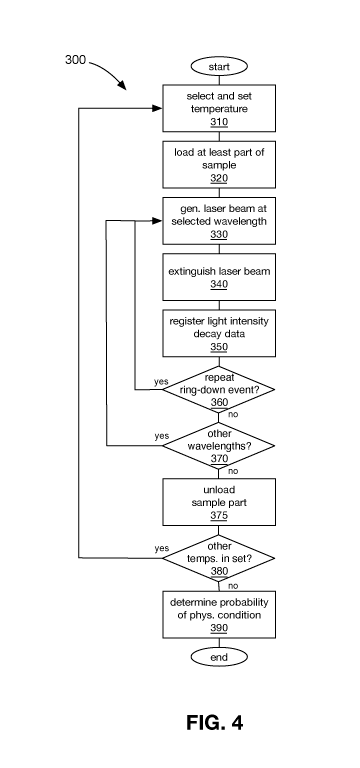
[0119] A method 300 of analyzing a sample using the CRDS system 20 of FIG. 1
is shown
in FIG. 4. Traditionally, the sample to be analyzed using CRDS is desorbed at
a single
temperature. In the method 300, a part of a sample in a thermal desorption
tube is first
desorbed at a first temperature, and then at least one additional part of the
sample may be
desorbed from the thermal desorption tube at at least one additional
temperature. In some
scenarios, it can be desirable to separate parts of the sample for analysis
with the CRDS
system 20. For example, acetone and ammonia can be desorbed from a thermal
desorption
tube at a lower temperature. As acetone and ammonia can overwhelm the spectra,
obfuscating other substances in the sample, it can be desirable to desorb and
analyze
portions of the sample at different temperatures to isolate various substances
from other
substances. In other embodiments, it can be desirable to desorb the sample at
the same
temperature two or more times, as some constituents of the sample may desorb
readily at
that temperature the first time and other constituents of the sample may
desorb less readily
at that temperature the first time, but may desorb equally readily the second
time. As the
other constituents may have readily desorbed, they are less present to desorb
the second
time and thus the other constituents are more isolated. The set of ordered
desorption
temperatures thus can include a single desorption temperature or an ordered
set of two or
more desorption temperatures.
[0120] Referring now to FIGS. 1, 3, and 4, the method 300 begins with the
setting of the
temperature of the heater 132 to a first of the ordered set of desorption
temperatures (310).
In this particular configuration, a set of one or more temperatures at which
the sample is to
be desorbed from the thermal desorption tube 104 can be ordered. In one
preferred
approach, the desorption temperatures are ordered from lowest to highest. In
another
embodiment, the ordered set of desorption temperatures can include two
desorption
27
CA 03135504 2021-09-29
WO 2020/198843
PCT/CA2020/050250
temperatures that are the same or similar. There can be benefit to desorbing a
portion of a
sample at a temperature to release readily desorbed components/compounds that
is then
analyzed, and then desorbing another portion of the sample at the same
temperature to
release less-readily desorbed components/compounds that can be analyzed with a
reduced
amount of the more readily desorbed components/compounds.
[0121] A first of the ordered set of desorption temperatures is selected, and
the heater
132 is operated to heat the thermal desorption tube 104 to the first
desorption temperature.
Once the thermal desorption tube 104 is heated to the first desorption
temperature via the
heater 132, the part of the sample that has been desorbed at the first
temperature is then
loaded into the ring-down cavity 84, as previously described (320). Upon
loading of the part
of the sample in the ring-down cavity 84, a laser beam is generated by one of
the lasers 24,
28 that is tuned to one of a set of wavelengths (330). The set of wavelengths
can be selected
from the wavelengths at which the lasers 24, 28 can produce a beam in any
manner as
desired. The generated laser beam is directed through the first optical
modulator 60,
reflected by the mirror 64, through the second optical modulator 68, and
reflected by the
mirror 72 into the ring-down chamber 80. The optical modulators 60, 68
attenuate the
working beam 52 somewhat to modulate its intensity.
[0122] When the working beam 52 reaches the front cavity mirror 88a, a
fraction, about
0.1%, penetrates the front cavity mirror 88a to enter the ring-down cavity 84.
The majority
.. of the working beam, about 99.9%, is initially reflected back along the
same path to the
working laser 24 or 28.
[0123] Initially, the ring-down cavity 84 is not illuminated. Light enters the
ring-down cavity
84 and, as the majority of the light in the ring-down cavity 84 is reflected
between the two
cavity mirrors 88, the amount, or power, of light in the ring-down cavity 84
starts increasing
.. as further light is introduced from outside via the working beam 52. A
certain fraction of the
light leaks out past the cavity mirrors 88. It takes a duration of time to
"fill" the ring-down
cavity 84 with light, and this can occur when the cavity length is equal to an
adjacent
resonance length of the ring-down cavity 84 for the tuned laser. At that
point, there is an
equilibrium between the incoming light and the leakage.
28
CA 03135504 2021-09-29
WO 2020/198843
PCT/CA2020/050250
[0124] Once this equilibrium is achieved, the laser beam directed into the
ring-down cavity
84 is extinguished (340). The laser beam entering the ring-down cavity 84 can
be
extinguished in a number of manners. In the particular embodiment, the
digitizer 264 sends
a trigger pulse to the timing circuit 260 to cause the optical modulators 60,
68 to extinguish
the laser light provided to the ring-down cavity 84. In other embodiments, the
laser can be
turned off, or detuned so that it does not resonate for the configured cavity
length, etc.
[0125] The timing circuit 260 simultaneously directs the first and second
optical modulators
60, 68 to attenuate the light beam at or close to an attenuation limits of the
optical modulators
60, 68 to reduce an intensity of the light beam from the first optical
modulator 60. In the
CRDS system 20, by directing both optical modulators 60, 68 to shut off
simultaneously, the
amount of light deflected by the first optical modulator 60 during the short
span of time is
markedly reduced by the second optical modulator 68 as it is shutting down.
[0126] The second optical modular 68 greatly increases the attenuation
achieved via the
first optical modulator 60 alone. In the currently described embodiment, if
the first optical
modulator 60 can attenuate by 30 dB, and the second optical modulator 68 can
attenuate
by an additional 30 dB, with the total attenuation achieved via the optical
modulators 60, 68
being the sum of their attenuation, or 60 dB. During filling of the ring-down
cavity 84 with
light, the optical modulators 60, 68 attenuate the working beam 52 to modulate
its intensity.
In the present configuration, each of the optical modulators 60, 68 attenuate
the working
beam 52 by 5 dB, for a total attenuation of 10dB. As a result, each of the
optical modulators
60, 68 can still further attenuate the working beam 52 by 25 dB for a total
further attenuation
of 50 dB during the extinguishing of the working beam 52. In a conventional
setup, one
optical modulator would have to attenuate a working beam by 10 dB, leaving 20
dB of further
attenuation available for extinguishing the working beam. As will be
understood, the working
beam 52 can be extinguished much more rapidly via 50 dB of further attenuation
via the two
optical modulators 60, 68 than with one optical modulator with 20 dB of
further attenuation.
As a result, the amount of additional light introduced into the ring-down
cavity 84 after the
optical modulators 60, 68 have been directed to shut down is a small fraction
of the light
further introduced by a single optical modulator setup in a conventional CRDS
system. By
extinguishing the working beam 52 more quickly, the measured decay of light in
the ring-
down cavity 84 is less affected by the additional light during the ramp-down
times of the
29
CA 03135504 2021-09-29
WO 2020/198843
PCT/CA2020/050250
optical modulators 60, 68, thus granting higher precision when matching the
observed decay
times against known decay times.
[0127] Extinguishing of the laser light provided to the ring-down cavity 84
commences a
ring-down event. The resonating laser light provided to the ring-down cavity
84 can be
extinguished in other manners in alternative embodiments, such as, for
example, by
detuning the laser. By initiating the triggering of a ring-down event via a
threshold, the ring-
down event can be timed to occur during the peak while the ring-down cavity 84
is in
resonance with the laser light, and not on one side of the peak. Further, as
the bandwidth of
the resonance is about 10 millivolts, the resolution of the piezo driver 248
is insufficiently
granular to properly track the peak.
[0128] During the ring-down event, the control module 204 registers light
intensity decay
data reported by the liquid nitrogen-cooled detector 100 exiting from the back
end of the
ring-down cavity 84 (350). The ring-down event lasts about ten microseconds in
the present
configuration, but can last a longer or shorter time in other embodiments. The
light decay
time is about two microseconds.
[0129] It is then determined if the ring-down event is to be repeated (360).
In this
embodiment, the CRDS system 20 is configured to collected light intensity
decay data for
500 ring-down events.
[0130] About 100 microseconds after when the ring-down event is triggered, the
timing
circuit 260 directs the optical modulators 60, 68 to recommence allowing the
working beam
52 through to the ring-down cavity 84. If the light intensity decay data from
500 ring-down
events has been captured, the control module 204 stops operation of the piezo
driver 248,
and then determines the decay rate from the ring-down event data, which refers
to the light
intensity decay data and may be used interchangeably herein. If, instead, it
is determined at
360 that further light intensity decay data is to be collected, the control
module 204 continues
to direct the piezo driver 248 to actuate the rear cavity mirror 88b. As the
aggregate voltage
attains a maximum or minimum, it commences to proceed in an opposite
direction. That is,
if the aggregate voltage AV was increasing prior to achieving the maximum
voltage in its
range, the aggregate voltage AV then decreases back towards the voltage
corresponding
with the resonance length RL. Alternatively, if the aggregate voltage AV was
decreasing
CA 03135504 2021-09-29
WO 2020/198843
PCT/CA2020/050250
prior to achieving the minimum voltage in its range, the aggregate voltage AV
then increases
back towards the voltage corresponding with the resonance length RL. In this
manner, ring-
down events are triggered in both directions.
[0131] The light intensity decay data is collected as quickly as possible, as
various outputs
can drift. For example, the piezo actuators 252 can have a settling time
referred to as piezo
creep.
[0132] In other embodiments, any number of ring-down events can be employed at
each
wavelength and desorption temperature. In one embodiment, the ring-down events
at a
wavelength and desorption temperature can be performed until a desired level
of light
intensity decay data has been collected. The light intensity decay data
collected thus far can
be quickly analyzed as it is collected to determine if it appears to be valid.
After a desired
number of ring-down events for which valid light intensity decay data is
collected, the system
can deem that sufficient data has been collected at that wavelength and
desorption
temperature. This can in many scenarios shorten the time required to perform
the analysis.
[0133] Upon collecting the light intensity decay data for the selected
wavelength, the light
intensity decay data for the particular sample, desorption temperature, and
wavelength may
be processed by the control module 204, such as by determining a decay rate
for each ring-
down event and averaging these values. Other approaches can be employed to
process the
ring-down event data.
[0134] It is then determined if there are other wavelengths in the set at
which the laser is
to be generated (370). If there are other wavelengths to be generated, the
method 300
returns to 330, at which the laser 24, 28 is tuned to generate a laser beam of
the newly
selected wavelength.
[0135] The process is repeated for lights of other wavelengths to generate an
absorption
spectrum for the sample at the particular desorption temperature. The light
intensity data
from the liquid nitrogen-cooled detector 100 provides or is readily converted
to, in effect,
light intensity decay data that indicates how quickly the light of the
particular wavelength
was absorbed by the part of the sample that was loaded into the ring-down
cavity 84.
[0136] For example, the light generated by the CO2 laser 24 provides
absorption
coefficients for a range of wavelengths. Similarly, absorption coefficients
can be generated
31
CA 03135504 2021-09-29
WO 2020/198843
PCT/CA2020/050250
for a range of wavelengths for the light from the carbon-13 02 laser 28. In
this manner, an
absorption spectrum can be developed for the sample.
[0137] Once an absorption spectrum across the set of wavelengths is generated
for the
part of the sample desorbed at the first temperature, the part of the sample
is unloaded from
the ring-down cavity (375). It is determined if there are other temperatures
in the ordered
set to which the thermal desorption tube 104 is to be heated to desorb other
parts of the
sample for analysis in the ring-down cavity 84 (380). If it is determined that
there are other
temperatures at which a part of the sample is to be desorbed, the heater is
set to the next
desorption temperature at 310. In the present embodiment, a next desorption
temperature
to which the thermal desorption tube 104 is heated is higher than the previous
desorption
temperatures(s) to which the thermal desorption tube 104 was heated. If the
ordered set of
desorption temperatures includes a single desorption temperature, the method
300 does
not return to 310.
[0138] As previously noted, desorption of the sample contained in the thermal
desorption
tube 104 at another temperature that is higher than other temperatures at
which the thermal
desorption tube 104 was previously desorbed can yield a different subset of
the compounds
/ substance in the sample.
[0139] Once the light intensity decay data has been collected for each of the
desorption
temperatures, the CRDS system 20 analyzes the light intensity decay data for
the set of
wavelengths and the set of desorption temperatures to determine a probability
that the
patient from which the sample was drawn has a particular physiological
condition or a
degree of a physiological condition (390). The probability is determined at
least indirectly
using a dataset of light intensity decay data for previously analyzed samples
for which the
presence or absence of the physiological condition or a degree of the
physiological condition
(i.e., lung cancer in the exemplary embodiment) has been identified. The
determination of
the probability can use a predictive model that is at least partially based on
the dataset of
light intensity decay data for previously analyzed samples.
[0140] The CRDS system 20 can determine the probability that the subject from
which the
analyzed sample was drawn has one of a set of discrete degrees of the
physiological
condition, and then present the most likely degree of the physiological
condition or the entire
32
CA 03135504 2021-09-29
WO 2020/198843
PCT/CA2020/050250
set of probabilities. Further, the CRDS system 20 can also provide a
confidence level for
each of the results.
[0141] The light intensity decay data collected at each desorption temperature
can be
analyzed at least indirectly using the dataset of light intensity decay data
for the previously
analyzed samples that is segregated by the same or similar desorption
temperatures.
Preferably, the dataset of light intensity decay data for the previously
analyzed samples was
collected using the same or a similar sequence of temperatures for desorbing
parts of the
sample. In an alternative embodiment, the light intensity decay data from two
or more
desorption temperatures from the sample can be combined together, and analyzed
using a
predictive model generated at least partially based on light intensity decay
data for
previously analyzed samples that is treated in the same or similar manner
(i.e., the light
intensity decay data for corresponding desorption temperatures is aggregated).
A predictive
model can be generated from the dataset of light intensity decay data for the
previously
analyzed samples. One preferred approach is by using supervised machine
learning.
[0142] The dataset of light intensity decay data for previously analyzed
samples
represents spectra for entire parts of the previously collected samples and
not any one
particular volatile organic compound. By adopting this more wholistic approach
to analyzing
a sample, there is less reliance on the identification of contentious volatile
organic
compounds to predict the probability that the sample currently being analyzed
comes from
a subject having the physiological condition. The subject can be a person or
another animal
or organism.
[0143] The predictive model is generated using machine learning techniques at
least
partially by using the dataset of light intensity decay data as a training
set.
[0144] It can be challenging to obtain a sufficiently large sample dataset for
predicting the
presence or absence of certain physiological conditions. Some pre-processing
steps can be
beneficial in such circumstances. This can be particularly true for certain
physiological
conditions.
[0145] In order to manage missing values in the spectrum, interpolation
techniques, such
as spline interpolation, using neighboring absorbance values in the spectrum
can be
employed. If the available wavelengths are not evenly spaced, average values
from
33
CA 03135504 2021-09-29
WO 2020/198843
PCT/CA2020/050250
comparable subjects identified by a k-nearest neighbor search can be used, as
can a VOC
regression approach to approximate missing values.
[0146] Where high variability is observed in the previously collected data, it
can be
attributable to natural VOC variations and other confounding variables.
Baseline correction
.. can be used to eliminate any unwanted trends, such as via the use of common
spectroscopy
detrending techniques (e.g., linear, quadratic, and Savitzky-Golay
detrending). Spectral
subtraction techniques can also be employed for highly concentrated VOCs like
acetone
and ammonia, which are common to all subjects and may be masking small,
important
details in the spectra.
[0147] Similarly, common normalization techniques can be used to improve
sample
consistency. In addition to those based on individual spectra (min-max, peak,
standard
normal variate normalization for example), methods that normalize across all
spectra (such
as multiplicative scatter correction) can be employed.
[0148] A comprehensive analysis of the spectra and clinical factors is used to
identify
unobvious relationships and confounders in the dataset of light intensity
decay data for
previously analyzed samples to improve data interpretation and identify
subgroups that are
incorporated into the predictive model. There are a number of confounding
factors in breath
VOC analysis that include age, sex, smoking, alcohol consumption, medication
use, and
other diseases. Unsupervised clustering techniques, along with supervised
predictive
models that classify spectra according to possible confounders, are used to
assess these
factors. Similarly, spectral data for different subgroups can be used to train
separate models
for lung cancer detection.
[0149] Features such as spectral derivative-based features, projected
features, and
wavelet transform-based features are being employed for feature extraction.
Derivative-
.. based features are particularly useful because they apply some inherent
baseline and scale
correction for inter-individual variability. Barcode features and a one-
dimensional form of the
local binary patterns (1D-LBP) can also be used. Further, features derived
from a time-series
of desorptions of samples at different temperature sequences can also be
employed.
[0150] The various pre-processing and feature extraction methods can be
combined,
.. along with the information found in the confounding factor and subgroup
analysis, to create
34
CA 03135504 2021-09-29
WO 2020/198843
PCT/CA2020/050250
the final classification system. To reduce system dimensionality and remove
unhelpful,
redundant features, a few feature selection techniques may be used. Statistics-
based filter
methods like minimum redundancy maximum relevance ("mRMR") selection can be
employed, as well as classification-based wrapper methods, like sequential
feature selection
("SFS") and genetic algorithm ("GA") selection. Simple support vector machine
("SVM"),
discriminant analysis (LDA and QDA), and KNN classifiers can be employed to
evaluate
features in the wrapper selection methods and to build and validate the
numerous
classification models.
[0151] Various alternative approaches and methods can be employed for
generating the
predictive model.
[0152] FIG. 5 shows a method 400 for generating a predictive model. In this
approach, a
set of desorption temperature sequences are identified for exploration. A
sequence of
desorption temperatures is an ordered set of temperatures to which the thermal
description
tube is heated to desorb parts of the sample contained therein. Desorption of
the sample
using a particular sequence of temperatures can enable different selective
parts of the
sample to be desorbed and analyzed separately, which can enable different
aspects of the
sample to be more readily identified. Certain features of a sample may be more
readily
apparent from the light intensity decay data captured for certain desorption
temperature
sequences. For example, if a first component/compound is desorbable from the
thermal
desorption tube 104 at a certain temperature and confounds a second
component/compound that is desorbable at a slightly elevated temperature,
features of the
light intensity decay data for a sample may become more apparent using a
desorption
temperature sequence that has a desorption temperature equal to that of the
first
component/compound, and then a subsequent desorption temperature equal to or
above
that of the second component/compound. These relationships between the
desorption
temperature sequences and the features exposed may not in some cases be
readily
apparent. As a result, the particular sequence which yields the best
correlation to the
presence or absence may not be readily apparent without exploration. In
another aspect, if
the light intensity decay data registered at two desorption temperature
sequences yield
substantially equal correlations to the subset(s) of samples drawn from
subjects having the
CA 03135504 2021-09-29
WO 2020/198843
PCT/CA2020/050250
physiological condition or a degree of the physiological condition, it may be
desirable to
select the shorter desorption temperature sequence, for example.
[0153] While the general method will be described with reference to the CRDS
system 20,
it will be understood that the approach may be conducted using a plurality of
local or
distributed CRDS systems and other computers using a common set of parameters
and
standard practices.
[0154] The method 400 commenced with the selection of sample (404). The sample
is
selected from a set of samples from subjects that have been identified as one
of having a
physiological condition and not having the physiological condition. Then a
desorption
temperature sequence is selected from a set of desorption temperature
sequences (408).
The set of desorption temperature sequences can be chosen based on scientific
evidence,
randomly, etc. The desorption temperature of the heater 132 is set to the next
desorption
temperature in the sequence (412). If the sequence is yet unprocessed, the
first desorption
temperature in the sequence is selected.
[0155] Next, a part of the sample is then desorbed and loaded (416). The
heater 132 is
heated to the selected desorption temperature from the sequence and a part of
the sample
is desorbed. the sample-loading system 112 loads the desorbed part of the
sample into the
ring-down cavity 84.
[0156] The control module 204 then operates one of the lasers 24, 28 to
generate a laser
beam of the selected wavelength. The laser beam is directed into the ring-down
cavity 84
to "fill" the ring-down cavity 84 with light.
[0157] Once the control module 204 determines that there is sufficient light
in the ring-
down cavity 84, the control module 204 directs the optical modulators to
extinguish the laser
beam that is directed into the ring-down cavity 84 (424).
[0158] The liquid nitrogen-cooled detector 100 registers the light intensity
exiting the ring-
down cavity 84 via the rear cavity mirror 88b (428). Light intensity decay
data corresponds
to the detected intensity of the light exiting the ring-down cavity 84 over
time, and is
transmitted to the control module 204. Upon completion of the ring-down, the
control module
204 determines whether to repeat the ring-down event (430). The ring-down
event may be
repeated many times to reduce the effect of abnormalities. If another ring-
down event is to
36
CA 03135504 2021-09-29
WO 2020/198843
PCT/CA2020/050250
be performed at the selected wavelength, the method 400 returns to 420,
wherein a laser
beam at the selected wavelength is generated. It is then determined if there
are other
wavelengths in the set to be used (432). It there are other wavelengths, the
method 400
returns to 420, at which a laser beam is generated at the next selected
wavelength. If,
instead, it is determined that there are no other wavelengths in the set, it
is determined if
there is another desorption temperature in the sequence (436). If there is at
least another
desorption temperature in the sequence, the next desorption temperature in the
sequence
is selected and the heater 132 is heated to that temperature to desorb another
part of the
sample at 412.
[0159] If, instead, it is determined that there are no other desorption
temperatures in the
sequence at 436, it is then determined whether there are other desorption
temperature
sequences to be explored (440). If there are other unexplored desorption
temperature
sequences, a next desorption temperature sequence is selected at 408. When a
new
desorption temperature sequence is selected, a new thermal desorption tube
from the same
subject is used, as the sample in the previously used thermal desorption tube
104 has been
at least partially desorbed.
[0160] Once all of the desorption temperature sequences have been explored, it
is
determined if there are any other samples in the set that have yet to be
analyzed (444). If
there still yet unanalyzed samples in the set, another sample is selected at
404 for analysis.
[0161] If, instead, it is determined that all of the samples have been
analyzed at 444, the
correspondence between the light intensity decay data and the identification
of the subjects
from which the samples are drawn as having the physiological condition or
degrees of the
physiological condition for each desorption temperature sequence is then
determined (448).
The correspondence between the light intensity decay data and the
identification of the
samples as having the physiological condition or a degree of the physiological
condition is
stronger when there is a set of features that are significantly more prevalent
in samples from
subjects identified as having the physiological condition or a degree of the
physiological
condition. That is, if there is a particular set of features that each occurs
in 85 percent of
subjects having a physiological condition and in 20 percent of subjects not
having the
physiological condition for a particular sequence of desorption temperatures,
then the light
intensity decay data for the sequence of desorption temperatures may have a
relatively good
37
CA 03135504 2021-09-29
WO 2020/198843
PCT/CA2020/050250
correlation to the presence or absence of the physiological condition in the
subjects from
which the samples are obtained. While this is an example, any pattern between
the light
intensity decay data and the presence of the physiological condition or a
degree of the
physiological condition can indicate the presence of a correlation between the
light intensity
.. decay data and the presence of the physiological condition or the degree of
the physiological
condition.
[0162] A desorption temperature sequence is then selected based on the
correspondence
between the light intensity decay data and the identification of the subject
from which the
samples were drawn as having the physiological condition or a degree of the
physiological
condition for each desorption temperature sequence (452). The desorption
temperature
sequence may be selected entirely based on the measured correlation, or on the
correlation
in combination with other factors. Other factors can determine the selection
of the sequence
of desorption temperatures, such as the number of desorption temperatures in
the
sequence, thereby determining the amount of time to perform the analysis.
[0163] A predictive model is then generated using the selected desorption
temperature
sequence at least partially selected based on the correlations (452).
[0164] Where a sequence of temperatures is used to desorb a sample from a
thermal
desorption tube, it can be unadvantageous to analyze parts of samples that are
desorbed
at certain temperatures. The desorption may be performed at certain
temperatures to
remove substances that are less of interest than those desorbed at other
temperatures.
[0165] FIG. 6 shows a method 500 of analyzing a sample via CRDS. In the method
500,
a part of the sample is desorbed at a first temperature and is, in effect,
discarded as it may
have little correlation to the presence or absence of a physiological
condition in a patient. A
second part of the sample is desorbed at a second temperature. The second part
of the
sample is deemed to have a relatively high correlation to the presence of the
physiological
condition or a degree of the physiological condition and is thus analyzed via
CRDS.
[0166] The method 500 commences with the setting of the temperature of the
heater 132
at a first desorption temperature by the control module 204 (510). Heating of
the heater 132
to the first desorption temperature causes the thermal desorption tube 104 to
be heated and
a first part of the sample to be desorbed. The sample-loading system 112 is
then directed
38
CA 03135504 2021-09-29
WO 2020/198843
PCT/CA2020/050250
by the control module 204 to expel the first part of the sample without
performing CRDS on
the first part. The first part of the sample may be expelled to the
surrounding atmosphere,
to a collection cannister, or may be removed from the path between the thermal
desorption
tube 104 and the ring-down cavity 84 via any other suitable approach. In a
presently
preferred embodiment, the first sample is expelled through the mass flow
controller 136 by
closing valves 124b and 124d, and by opening valves 124a, 124c, 124g, 124f,
and 124h,
much in the same manner that carbon dioxide and water are expelled from the
thermal
desorption tube 104.
[0167] After expelling the first part of the sample, the heater is heated to a
second
desorption temperature (530). The second desorption temperature is generally
higher than
the first temperature and, as a result, causes different substances to be
desorbed from the
thermal desorption tube 104. In other embodiments, the second desorption
temperature is
the same as or lower than the first desorption temperature. While a good
portion of some
components/compounds may have already been desorbed at the previous desorption
temperature, virtually all of other confounding substances may have been
desorbed as well,
thus facilitating the isolation of these components/compounds. The second part
of the
sample is then loaded into the ring-down cavity 84 for analysis, as described
above (540).
Next, the control module 204 operates one of the lasers 24, 28 to generate a
laser beam at
a selected wavelength (550). The laser beam is directed into the ring-down
cavity 84 to fill
the cavity with light. Once the ring-down cavity 84 is filled, the laser beam
is extinguished
(560). The liquid nitrogen-cooled detector 100 then registers the intensity of
the light exiting
the ring-down cavity 84 via the rear cavity mirror 88b (570). The light
exiting the ring-down
cavity 84 represents light intensity decay data that is registered by the
liquid nitrogen-cooled
detector 100 and transmitted to the control module 204.
[0168] Once the ring-down event is complete, it is determined whether to
repeat the ring-
down event again (580). As noted above, it can be desirable to repeat the ring-
down event
a number of times and then determine one or more collective metrics by
determining a decay
rate for the light intensity decay data for each ring-down and then averaging
the decay rates
to minimize the effect of aberrations. If another ring-down event is to be
repeated, a laser
.. beam is generated at the selected wavelength at 550. If, instead, no more
ring-down events
are to be performed, it is determined whether there are other wavelengths in
the set of
39
CA 03135504 2021-09-29
WO 2020/198843
PCT/CA2020/050250
wavelengths to be analyzed (590). If it is determined that there are other
wavelengths to be
analyzed, a laser beam of a next one of the wavelengths is generated at 550.
If, instead,
there are no more wavelengths to generate a laser beam at for performing CRDS,
the light
intensity decay data collected at 570 is then analyzed (595), after which the
method 500
ends. The collected light intensity decay data is then analyzed.
[0169] While the at least one processor that analyzes the light intensity
decay data and
generates a predictive model is shown and described as being fully integrated
with the other
elements of the CRDS system, in other embodiments, one or more of the at least
one
processor can be provided in a separate computer system that has storage and
performs
some or all of the functionality of the control module in the above-described
and illustrated
embodiment.
[0170] FIG. 7A shows a system 600 for analyzing a sample using CRDS in another
embodiment. The system 600 includes a CRDS system 604 similar to that of FIG.
1. The
CRDS system 604 has a control module 608 that has at least one processor for
controlling
operation of the various elements of the CRDS system 604. The control module
608 is in
communication with a computer system 612 over a data communications network
616. The
computer system 612 can be any single computer or multiple computers coupled
together
locally and/or remotely to provide the described functionality. The data
communications
network 616 can be any suitable medium enabling the control module 608 and the
computer
system 612 to communicate at least the light intensity decay data and any
associated
parameters associated therewith, such as wavelengths, the temperature at which
the at
least part of the sample was desorbed, as well as any other subject-specific
data, such as
the above-noted confounding factors, a subject identifier, time and location
information for
when and where the sample was analyzed, etc.
[0171] FIG. 7B shows a number of physical and logical components of the
computer
system 612, including a central processing unit ("CPU") 624, random access
memory
("RAM") 628, an input/output ("I/O") interface 632, a communications interface
636, non-
volatile storage 640, and a local bus 644 enabling the CPU 624 to communicate
with the
other components. The CPU 624 can include one or more processors and executes
at least
an operating system, as well as a spectra evaluation application. The RAM 628
provides
relatively responsive volatile storage to the CPU 624. The I/O interface 632
allows for input
CA 03135504 2021-09-29
WO 2020/198843
PCT/CA2020/050250
to be received from one or more devices, such as a keyboard, a mouse, etc.,
and outputs
information to output devices, such as a display and/or speakers. The
communications
interface 636 permits communication with other computing devices like the
control module
608 over computer networks such as the data communications network 616. The
non-
volatile storage 640 stores the operating system and programs, including
computer-
executable instructions for implementing the spectra evaluation application.
During
operation of the computer system 612, the operating system, the programs and
the data
may be retrieved from the non-volatile storage 640 and placed in RAM 628 to
facilitate
execution.
[0172] While, in the above-described embodiment, the light sources are two
lasers that
produce light in the mid-infrared range, it will be appreciated that other
light sources can be
employed. For example, a laser producing light in the visible spectrum or a
near-infrared
laser can be employed. Further, in some scenarios, the CRDS system can include
only one
laser, or three or more lasers, to generate the working beam.
[0173] Electro-optic modulators can be used in place of acousto-optic
modulators.
[0174] The acousto-optic modulators can be configured so that the frequency of
the
working beam is shifted up or down. As long as the net frequency shift
effected by the
acousto-optic modulators shifts the frequency of the working beam
significantly away from
the frequency of the working beam being generated by the laser(s) so that the
reflected light
is outside of the bandwidth of the laser light being generated, the amount of
interference
between the reflected light and the generated working beam can be minimized.
[0175] In other embodiments, more than two optical modulators can be employed
in a
CRDS system to provide further extinguishing capacity to more quickly
extinguish the
working beam at the commencement of a ring-down event. Further, in further
embodiments,
a single optical modulator can be employed.
[0176] One or more focusing lenses can be employed in other embodiments, and
translated to enable repositioning of the lenses to allow mode-matching of
each wavelength
of the lasers.
[0177] The same approach can be adopted for other types of resonant cavities,
and
particularly optical resonant cavities.
41
CA 03135504 2021-09-29
WO 2020/198843
PCT/CA2020/050250
[0178] Other types of events can be triggered as the cavity length is proximal
to the
resonance length of the cavity for the particular selected wavelength.
[0179] Analysis of the samples can be performed at pressure levels other than
one
atmosphere in other embodiments. The breadth of the absorption spectrum may
change
accordingly.
[0180] Although specific advantages have been enumerated above, various
embodiments
may include some, none, or all of the enumerated advantages.
[0181] While, in the above-described embodiment, the resonant cavity is a ring-
down
cavity, in other embodiments, other types of resonant cavities can be
employed.
.. [0182] Persons skilled in the art will appreciate that there are yet more
alternative
implementations and modifications possible, and that the above examples are
only
illustrations of one or more implementations. The scope, therefore, is only to
be limited by
the claims appended hereto.
42
CA 03135504 2021-09-29
WO 2020/198843
PCT/CA2020/050250
LIST OF REFERENCE NUMERALS
20 CRDS system
24 CO2 laser
28 carbon-13 02 laser
32 first laser beam
36 second laser beam
40 mirror
44 beam splitter
48 sampling beam
52 output beam
56 fast infrared detector
60 first optical modulator
64 mirror
68 second optical modulator
72 focusing lens
76 mirror
80 ring-down chamber
84 ring-down cavity
88 cavity mirror
88a front cavity mirror
88b rear cavity mirror
92 mirror mounts
96 micrometer
96a mechanized micrometer
43
CA 03135504 2021-09-29
WO 2020/198843
PCT/CA2020/050250
96b piezoelectric micrometer
100 liquid nitrogen-cooled detector
104 thermal desorption tube
105 stainless-steel casing
106 aperture
107 receiving end
108 foam separator
109 sorbent material
110 foam separator
112 sample-loading system
116 nitrogen gas source
120 conduit
120a gas intake line
120b desorption tube line
120c sample outlet line
124 solenoid valve
124a gas inlet valve
124b auxiliary gas inlet valve
124c gas intake line valve
124d cavity inlet valve
124e pathing valve
124f forward valve
124g rearward valve
124h sample outlet valve
124i cavity outlet valve
44
CA 03135504 2021-09-29
WO 2020/198843
PCT/CA2020/050250
124j vacuum cutoff valve
124k vacuum intake valve
128 pressure meter
130a, 130b filter
132 heater
136 mass flow controller
140 outlet line
144 pressure meter
148 vacuum pump
150 pump intake line
200 electronic control subsystem
204 control module
205 processor
206 storage
208 RF driver
212 grating actuator
216 output coupler piezo
220 high-voltage amplifier
224 DAQ card
228 actuator driver
232 amplifier
236 oscilloscope
240 temperature controller
244 relay board
248 three-channel piezo driver
CA 03135504 2021-09-29
WO 2020/198843
PCT/CA2020/050250
252 piezo actuator
256 RF driver
260 timing circuit
264 digitizer
RL resonance length
300 method
310 select and set temperature
320 load at least part of sample
330 generate laser beam at selected wavelength
340 extinguish laser beam
350 registering light intensity decay data
360 repeat ring-down event?
370 other wavelengths?
375 unload sample part
380 other temps. in seq.?
390 determine probability of physiological condition
400 method
404 select sample
408 select temperature sequence
412 set heater temperature
416 load a part of sample
420 generate laser beam at wavelength
424 extinguish laser beam
428 register light intensity decay data
430 repeat ring-down event?
46
CA 03135504 2021-09-29
WO 2020/198843
PCT/CA2020/050250
432 other wavelengths?
436 other temperatures?
436 determine probability of physiological condition
440 other temperature sequence?
444 other samples?
448 identify temperature sequence with greater correlation
452 select temperature sequence
456 generate predictive model
500 method
510 set heater to first temperature
520 expel first part of sample
530 set heater to second temperature
540 load second part of sample
550 generate laser beam at selected wavelength
560 extinguish laser beam
570 register light intensity decay data
580 repeat ring-down event?
590 other wavelengths?
595 analyze collected light intensity decay data
600 system
604 CRDS system
608 control module
612 computer system
616 data communications network
624 processor
47
CA 03135504 2021-09-29
WO 2020/198843
PCT/CA2020/050250
628 RAM
632 I/O interface
636 communications interface
640 non-volatile storage
644 bus
648 database
48