Note: Descriptions are shown in the official language in which they were submitted.
CA 03135533 2021-09-29
WO 2020/253923
PCT/DK2020/000086
SPORTS SHOOTING TARGET AND CORRESPONDING LAUNCHING DEVICE AND
APPARATUSES
TECHNICAL FIELD
The present invention relates to the field of sports shooting targets and
apparatuses for
launching such targets and more particularly to improvements of targets and
apparatuses with
the aim to reduce environmental hazards caused by the targets and to improving
trajectory
stability of targets after launching from launching apparatuses.
BACKGROUND OF THE INVENTION
Prior art sports shooting targets, such as clay pigeons, are made of limestone
and a binding
material, such as pitch, bitumen or another organic material and weighs
typically about 105 to
110 grams. The binder materials may contain components that can pose a
potential risk to the
environment. The binder material may contain a mixture of different
hydrocarbons called
polycyclic aromatic hydrocarbons (PAH) and some of these are known to be
toxic.
Prior art launching apparatuses comprise a throwing arm that can be rotated
about a rotational
axis and onto which a sports shooting target is provided from a supply
container at a distance
from the rotational axis. Longitudinally opposite the rotational axis, the
throwing arm has a free
end portion from which a target provided on the arm will be launched due to
the centrifugal
force exerted on the target by the rotation of the throwing arm. Traditional
sports shooting
targets are not provided with stabilizing means that act to stabilize the
trajectory or trajectory
of the target after it has left the launching apparatus. The lack of
stabilizing means in the prior
art target may not pose a serious problem for targets of relatively heavy
weights, but for very
light weight targets, the trajectory will be rather unstable and
unpredictable.
The use of traditional clay pigeons is prohibited in many locations in the
world due to the risk
of polluting the environment. Especially, in the vicinity of ground water
drillings, the use of
traditional clay pigeons is widely prohibited. There is a current tendency
that the prohibition of
the use of traditional clay pigeons may be generally implemented during the
coming years.
Hence there is a need to provide a replacement of the traditional clay pigeon
that solves the
environmental issues, but still make traditional clay pigeon shooting
possible, substantially
without altering the behavior of the new kind of sports shooting target after
launching from a
launching apparatus. The new kind of sports shooting target should thus be
able to offer a
hunter or sports shooter the same experience as the traditional type of clay
pigeon does.
1
CA 03135533 2021-09-29
WO 2020/253923
PCT/DK2020/000086
There is hence a need for a sports shooting target and corresponding launching
apparatus
that will solve both the environmental issues addressed above and provide a
more stable and
predictable trajectory of the target.
OBJECTIVE OF THE PRESENT INVENTION
An object of the present invention is to provide a lightweight sports shooting
target that despise
its low weight has improved trajectory stability after launching.
A further object of the present invention is to provide a sports shooting
target that reduces or
even eliminates the risk of polluting the environments.
A further object of the present invention is to provide a sports shooting
target that is cheap to
manufacture, especially much cheaper than traditional clay pigeons.
A further object of the invention is to provide a very light weight sports
shooting target, thereby
rendering it possible to ship large quantities of targets throughout the world
at a very low prize.
A further object of the present invention is to provide a sports shooting
target with enhanced
visibility after launching.
A further object of the present invention is to provide launching devices and
apparatuses that
is specifically suited to launch the very light and fragile target of the
invention without damaging
the target. During use of the invention, the target must be accelerated from
zero rotational
speed to a very high final rotational speed, typically in the order of 20000
rpm and it is
absolutely essential that the acceleration of the target and its release from
the launching device
does not stress the target and causes disintegration of the target.
A further object of the invention is to provide a launching apparatus that can
function
automatically and that can accommodate a very large number of targets ready
for launching.
It is a further object of the invention to provide a version of a launching
apparatus that can
stand on a suitably support means on the ground or on the ground itself.
It is a further object of the invention to provide a programmable launching
apparatus that can
easily be programmed by a user.
2
CA 03135533 2021-09-29
WO 2020/253923
PCT/DK2020/000086
It is a further object of the invention to provide an advantageous method for
performing sports
shooting activities, particularly skeets shooting, and event at which a
plurality of sports shooting
targets can be launched such that a variety of interesting scenarios can be
created.
It is a further object of the invention to provide a version of a launching
apparatus that is hand-
held.
DISCLOSURE OF THE INVENTION
The above and further objects and advantages are according to a first aspect
of the invention
obtained by a sports shooting target according to the invention.
The present invention provides an environmentally advantageous alternative to
traditional clay
pigeons. The sports shooting targets of the invention moves substantially in
the same manner
as traditional clay pigeons, such that a sports shooter will have
substantially the same
experience and pleasure when using the sports shooting targets of the
invention as when using
traditional clay pigeons.
Due to their low weight, the sports shooting targets of the invention can be
manufactured at a
central location, where they can be cheaply manufactured, and distributed
throughout the
world from this centralized location.
An important feature of the sports shooting target according to the present
invention is that its
weight is very much reduced compared to traditional sports shooting targets.
The weight of
such prior art targets is typically in the range 100 to 110 grams, whereas the
sports shooting
target according to the present invention typically weighs less than 10 grams,
typically in the
range 6 to 8 grams.
Another important feature of the sports shooting target according to the
present invention is
that it is configured to obtain maximum directional stability, such that it ¨
despise the very low
weight of the target ¨ is able to follow a stable trajectory in space after
being launched from a
.. launching apparatus. According to the invention, this stabilizing effect is
obtained by
gyroscopic means.
In an embodiment of the sports shooting target according to the invention, a
combined gyro-
stabilizing effect and a forward propelling effect is obtained by configuring
the target as a
circular object that after launching rotates about its rotational axis ¨
whereby the gyro-
.. stabilizing effect is obtained ¨ and where the circular object is provided
with fan means that,
when rotating about the rotational axis of the target, propels the target in a
desired forward
3
CA 03135533 2021-09-29
WO 2020/253923
PCT/DK2020/000086
direction along a trajectory originating from a launching apparatus that
provides the necessary
rotation of the target that ensures the gyroscopic effect and the forward
propulsion of the target
along the trajectory. Different embodiments of targets according to the
invention are shown
and described below.
In the following, the term "propelling means" and "propelling effect" are used
repeatedly. By
"propelling means" is meant means (elements, members, etc.) provided as a part
of the sports
shooting target according to the first aspect of the invention, and which
propelling means
functions to move the target along a trajectory in the air after the target
has been launched by
the apparatus according to the second aspect of the invention. The propelling
effect is the
.. forward moving effect caused by the propelling means along its trajectory.
Still another important feature of the sports shooting target according to the
first aspect of the
present invention is that it is made of a biodegradable material in order to
reduce or eliminate
environmental hazards.
The present invention comprises five aspects: The first aspect is a target
according to the
invention; the second aspect is a launching device configured to launch the
target when it has
been rotated to a desired final rotational speed; the third aspect is an
apparatus comprising
the launching device according to the second aspect of the invention; the
fourth aspect is a
method of launching targets for skeet shooting and similar sport shooting
activities; and the
fifth aspect is a hand-held apparatus comprising the launching device
according to the second
aspect of the invention.
According to a first aspect of the present invention there is thus provided a
sports shooting
target made of a biodegradable material, the target having a rotational axis
and attachment
means configured for releasable attachment of the target to a launching head
of a launching
device according to the second aspect of the invention, where the target is
provided with
trajectory stabilizing means that are configured to stabilize the trajectory
of the target by gyro
effect caused by rotation about the rotational axis, which stabilizing means
further function as
propelling means that cause forward movement of the target along its
trajectory due to the
rotation about said rotational axis, when the target is rotating and released
form the launching
device, where the stabilizing means comprises a fan comprising fan blades that
rotate in unison
with the target, when the target rotates, such that the stabilizing means both
provides the
stabilizing gyro effect and forward propulsion (movement) of the target along
a chosen
trajectory; where:
4
CA 03135533 2021-09-29
WO 2020/253923
PCT/DK2020/000086
- the sports shooting target comprises a hub portion configured for
releasable
attachment to a corresponding portion of a launching head of a launching
device, which
portion of the launching head, when the target is attached to it, can rotate
said target
and release it from the launching device, when a desired terminal rotational
speed has
been reached; and
- the hub portion is provided with an inner circumferential surface
facilitating release of
the target from the portion of the launching head and defining an inner space;
- the target comprises a plurality of concentric ring members arranged
about the
rotational axis of the target at different distances r5, r6, r7 from the
rotational axis and
outside the hub portion; and
- the stabilizing means comprises first fan blades that extend radially
from the hub portion
to the ring member provided at the largest distance from the rotational axis
and second
fan blades that extend radially between two adjacent ring members.
In an embodiment of the first aspect the inner circumferential surface of the
hub portion is
conical.
In an embodiment of the first aspect the ring members have cross-sectional
shapes comprising
curved first and second side faces, where the first and second side faces meet
at a
substantially sharp edge portion, thereby optimizing the aero-dynamic
properties of the
respective ring members.
In an embodiment of the first aspect the second fan blades are provided
between the outermost
ring member and the adjacent ring member.
In an embodiment of the first aspect the inclination angle of the fan blades
relative to the (x, y)
plane of the target increases towards the hub portion.
In an embodiment of the first aspect, the hub portion of the target comprises
inwardly sloping
surfaces that converge towards the longitudinal rotational axis of the target,
and are of similar
extension and slope angle relative to the longitudinal axis, whereby it
becomes possible to
attach the hob portion of the target to the launching head from either side of
the target, i.e. the
target according to this embodiment is reversible or "turnable".
According to a second aspect of the present invention there is provided a
launching device for
launching the target according to the first aspect, the launching device
comprising a launching
head configured such that the hub portion of the target can be positioned on
the launching
head, where the launching head comprises a plurality of pivotally mounted
retaining claw
5
CA 03135533 2021-09-29
WO 2020/253923
PCT/DK2020/000086
members that are configured to be able to pivot between a first state, in
which the claw
members retain the hub portion of the target to the launching head and a
second state, in
which the claw members release the hub portion of the target from the
launching head, where
the apparatus is provided with a longitudinally displaceable shaft member or
rod that is
functionally connected to the claw members such that a longitudinal
displacement of the shaft
member results in a pivotal movement of the claw members, whereby a
longitudinal
displacement of the shaft member from a first longitudinal position of the
shaft member to a
second longitudinal position of the shaft member makes the claw members pivot
between the
first state and the state and/or vice versa, where the device is provided with
shaft member
operating means configured to displace the shaft member between the first and
second
longitudinal positions and launching head rotating means configured to rotate
the launching
head and to accelerate the launching head from substantially zero retational
speed to a
maximum rotational speed, at which maximum rotational speed of the launching
head, the hub
portion of the target is released from the launchnig head.
In an embodiment of the second aspect the pivotal movement of the retaining
claw members
is obtained by engagement of an inner guide member that is fixedly attached to
the longitudinal
shaft member in the launching head and a correspondingly shaped recess or
extension in the
retaining claw members, and where an outer portion or extension of the claw
members are in
contact with an inner circumferential surface of the launching head, such that
when the
longitudinal shaft member is displaced in the positive longitudinal direction
(z), the retaining
claw members are forced to pivot between the state where they retain the hub
portion of the
target to the launching head, and the state where they release the hub portion
of the target
from the launching head.
In an embodiment of the second aspect the device comprises a first motor (for
instance an
electro motor) comprising a rotational axle and comfigured to rotate the
launching head upon
which the target can be placed; and wherein the launching head comprises:
- an inner guide member fixedly connected to the rotational axle and provided
with a
circumferentially extending guide recess or groove formed for engagement with
an
inwardly extending protrusion on the retaining claw members;
- an outer guide member comprising an inner space that surrounds the inner
guide
member, which outer guide member is configured to undergo a longitudinal
displacement (D) relative to the inner guide member and to rotate in unison
with the
inner guide member, where the outer guide member on a wall portion of the
inner space
6
CA 03135533 2021-09-29
WO 2020/253923
PCT/DK2020/000086
hereof is provided with a circumferentially extending recess or groove formed
for
engagement with a corresponding outer extension of the retaining claw member;
- a plurality of retaining claw members each provided with an inner protrusion
in
engagement with the circumferentially extending guide recess or groove on the
inner
guide member and an outer protrusion in engagement with the circumferentially
extending recess or groove;
whereby a longitudinal displacement (D) of the outer guide member relative to
the inner guide
member will cause the retaining claw members to pivot between said two states.
In an embodiment of the second aspect the device comprises longitudinal
displacement means
configured to displace the outer guide member in a direction (D) relative to
the inner guide
meand, where the longitudinal displacement means comprises:
- a longitudinal displacement motor or similar means operatively connected
to the shaft
member or rod via a rotation-to-displacement mechanism that converts a
rotational
movement provided by the longitudinal displacement motor to a longitudinal
displacement (D);
- a laterally extending plate member functionally connected to the outer
guide means
such that a longitudinal displacement (D) of the plate member causes the outer
guide
member to undergo a longitudinal displacement relative to the inner guide
member;
- where the shaft member or rod is connected to the laterally extending
plate member.
In an embodiment of the second aspect the outer guide means is configured to
be able to
undergo the above described longitudinal displacement as well as rotation in
unison with the
inner guide member.
In an embodiment of the second aspect the outer guide member is rotatably
connected to the
laterally extending plate member via a ball bearing which makes it possible
for the outer guide
member to undergo both langitudinal displacement and to rotate in unison with
the inner guide
means.
In an embodiment of the second aspect, the retaining claw members comprise an
upper
section (I) and a lower section (II), the upper section comprising a retaining
claw configured
for retaining engagement with the hub portion of the target according to the
first aspect, and
extending above a line L connecting the center points of the inner extension
and the outer
extension of the claw member, and the lower section extending below the line
L, where the
retaining claw member has its center of gravity located on the line L, wehere
the launching
7
CA 03135533 2021-09-29
WO 2020/253923
PCT/DK2020/000086
device is configured suct that when the retaining claw members release the
target from the
launching head, the line L forms an angle with the longitudinal rotational
axis R of the launching
head of substantially 90 degrees.
Thereby, the section I of the claw member located above the center of gravity
and the section
II of the claw member located below the center of gravity are exposed to equal
centrifugal
forces, when the launching head rotates about the longitudinal rotational axis
R. This
configuration of the claw members results in that the force which must be
transferred from the
the longitudinal displacement motor via the longitudinally extending shaft or
rod to the outer
extension of the retaining claw member that is required for releasing the
target from the
launching head is minimized.
Acording to a third aspect of the present invention there is provided a
launching apparatus
comprising one or more launching devices according to the second aspect of the
invention,
where the launching apparatus further comprises:
- for each of the launching devices, at least one magazine or container
configured to
contain a plurality of targets according to the first aspect of the invention;
- for each of the launching devices means configured to transfer a target
to the launching
head of the launching device;
- for each of the launching devices, a pivot mechanism operated by pivot
operating
means such that the launching device can be pivoted to a desired launching
angle
relative to horizontal that is desired for a specific application of the
apparatus;
- control means configured to control one or more of the following
functions of the
apparatus: loading of a target onto the launching head, starting rotating the
launching
head with the target thereon and acceleration it to a final desired rotation
speed at
which the target can be released from the launching head, adjusting the pivot
angle of
the launching devices;
- sensor means configured to determine if a desired final rotational speed
of the
launching head has been reached and if this is the case, instructing the
control means
to effect the release of the target by pivoting the retaining claw members to
pivot to the
state in which the target is released from the launching head.
In an embodiment of the third aspect, the launching apparatus comprises
programmable
control means configured to control the operation of the functions of the
apparatus and the
functions of the one or more launching devices provided in the apparatus, the
programmable
control means compriseng a control unit, such as a microcontroller, where the
control unit is
8
CA 03135533 2021-09-29
WO 2020/253923
PCT/DK2020/000086
configured to receive control signals from a user control panel, control
signals from a user
programming interface and a release process activation signal from a user
interface, such as
a pedal; and where the control unit is configured to provide control signals
for controlling
functionalities of the apparatus, where these control signals comprise one or
more of the
following:
- a first control signal controlling rotation of the magazines of the
apparatus, such that a
desired magazine is positioned correctly for loading a target onto the
launching head of a
specific launching device;
- a second control signal controlling displacement of the target receiving
tray between a
113 position, in which a target is picked up from the magazine above the
tray and a position,
in which the target can be loaded onto the launching head;
- a third control signal controlling the elevation angle of the launching
device;
- a fourth control signal controlling initiation of the release procedure
of the target;
- a fifth control signals controlling the azimuth angle of the launching
device;
- a sixth control signal that indicated if the desired final rotational speed
of the launching
head has been reached and hence, that the target can be released from the
launching
head;
- a seventh control signal providing the control unit with user definable
information from a
user control panel;
- an eight control signal providing the control unit with programming
information from a user
programming interface that allows a user to progranm functionalities of the
apparatus.
- A ninth control signal providing the control unit with a trigger signal
that initiates the release
procedure of the launching device.
In an embodiment of the third aspect, one or both of the control signals from
the user
programmable interface and trigger signal are provided to the control unit by
wireless
communication means.
In an embodiment of the third aspect, the control unit is configured to
provide and/or receive a
control signal to/from other launching apparatuses according to the invention,
such that a chain
of interconnected launching apparatuses according to the invention can be set
up.
According to a fourth aspect of the present invention, there is provided a
method of launching
targets for skeet shooting and similar sport shooting activities, the method
comprising:
- providing at least one launching appratus according to the third aspect
of the invention;
- providing a plurality of targets according to the first aspect of the
invention;
9
CA 03135533 2021-09-29
WO 2020/253923
PCT/DK2020/000086
- loading targets into a magazine of the launching apparatus(es);
- from a magizine of each specific of said launching apparatus(es) loading
a target onto
the launchnig head of one or more launching devices provided in the one or
more of
the launching apparatus(es);
-
adjusting the elevation angle of each individual launching device to a desired
elevation
angle value;
- adjusting the azimuth angle of each individual launching device to a
desired azimuth
value;
- defining a final rotational speed of the launching head of each
individual launching
device at which rotational speed the target shall be released from the
specific launching
head;
- by means of a user operable means, such as a pedal, initiating the
release procedure
for the target located on the launching head of the specific launching device.
In an embodiment of the fourth aspect, a plurality of functionally
interconnected launching
apparatuses according to the third aspect of the invention are provided and
the steps defined
above are executed for each individual of the plurality of launching
apparatuses.
Acording to a fifth aspect of the present invention there is provided hand-
held launching
apparatus configured to launch a target according to the first aspect of the
invention, where
the hand-held launching apparatus comprising a launching device according to
the second
aspect of the invention, where the hand-held launching apparatus further
comprises:
- control means configured to control one or more of the following
functions of the
apparatus, starting rotating the launching head with the target thereon and
acceleration it to a final desired rotation speed at which the target can be
released
from the launching head;
- sensor means configured to determine if the desired final rotational speed
of the
launching head has been reached and if this is the case instructing the
control means
to effect the release of the target by pivoting the retaining claw members to
the state
in which the target is released from the launching head;
- user-operating trigger means configured to start the rotation of the
launching head.
10
CA 03135533 2021-09-29
WO 2020/253923
PCT/DK2020/000086
BRIEF DESCRIPTION OF THE DRAWINGS
Further benefits and advantages of the present invention will become apparent
after reading
the detailed description of non-limiting exemplary embodiments of the
invention in conjunction
with the accompanying drawings, wherein
figure 1 shows a schematic perspective view of a first embodiment of a sports
shooting target
according to the invention seen from above:
figure 2 shows a schematic perspective view of the first embodiment of a
sports shooting target
according to the invention seen from below:
figure 3 shown a schematic plane view of the first embodiment of the sports
shooting target
according to the invention seen from above;
figure 4a and 4b show a schematic cross-sectional side view of a second
embodiment of the
sports shooting target according to the invention;
figure 5 shows a schematic view illustrating a third embodiment of the target
according to the
invention together with a corresponding launching head of a launching
apparatus according to
an embodiment of the invention;
figure 6 shows a launching head according to an embodiment of the invention
configured to
interact with the sports shooting target according to the first and second
embodiments of
targets shown in figures 1, 2 and 3;
figure 7 shows schematic views of the various main parts of the launching head
shown in figure
6;
figure 8 shows a second embodiment of a launching head according to the
invention configured
to interact with the second and third embodiments of the target according to
the invention
shown in figures 4 and 5;
figure 9 shows a schematic plane view of a portion of a target according to a
fourth embodiment
of the target according to the invention;
figure 10 shows a schematic representation of a second embodiment of a
launching head
according to the invention;
11
CA 03135533 2021-09-29
WO 2020/253923
PCT/DK2020/000086
figure 11 shows a schematic side view of a hand-held version of a launching
device according
to the invention;
figure 12 shows a schematic view of a first embodiment of a launching
apparatus comprising
operating means configured to operate the launching head between a state, in
which the target
is attached to the launching head and a state, in which the target I released
from the launching
head;
figure 13 shows a schematic side view of a launching apparatus according to an
embodiment
of the invention;
figure 14 shows a schematic representation of a top view of an embodiment of a
launching
apparatus according to the invention;
figure 15 shows a schematic view of a second embodiment of operating means
configured to
operate the launching head between a state, in which the target is attached to
the launching
head and a state, in which the target I released from the launching head;
figure 16 shows a schematic view of a third embodiment of operating means
configured to
operate the launching head between a state, in which the target is attached to
the launching
head and a state, in which the target I released from the launching head;
figure 17 shows a schematic view of a fourth embodiment of operating means
configured to
operate the launching head between a state, in which the target is attached to
the launching
head and a state, in which the target I released from the launching head;
figure 18 shows a schematic view of a fifth embodiment of operating means
configured to
operate the launching head between a state, in which the target is attached to
the launching
head and a state, in which the target I released from the launching head;
figure 19(a) and 19(b) shows a schematic view of a fourth embodiment shown in
figure 17
embodiment of operating means configured to operate the launching head between
a state, in
which the target is attached to the launching head and a state, in which the
target I released
from the launching head, shown in the two states of the operation means;
figure 20 is a schematic illustration of the functional principle of a target
retaining and releasing
mechanism of an embodiment of a launching device according to the invention;
12
figure 21 is a schematic perspective a partly sectional view of the upper
portion (i.e. the portion
that contains the launching head upon which the target is placed) of an
embodiment of a
launching device according to the invention;
figure 22 is a perspective and partly exploded view of an embodiment of the
launching head
and various associated drive means;
figure 23 is a schematic, perspective and partly exploded view of an
embodiment of a launching
apparatus according to the invention;
figure 24a to 24c are schematic perspective views of the launching device and
launching head
used in the apparatus shown in figure 23;
figure 25 is a perspective view of details of the launching head of the
embodiment shown in
figures 20 to 24;
figure 26 is a schematic perspective view of a retaining claw member used in
the embodiment
shown in figures 20 to 25;
figure 27 is a schematic representation of a portion of a launching apparatus
according to an
embodiment of the invention illustrating possible pivotal and rotational
movements of the
launching devices of the apparatus; and
figure 28 is a schematic block diagram of an embodiment of a control system
and user interface
means according to the invention.
DETAILED DESCRIPTION OF THE INVENTION
The principles of the invention will be illustrated by various embodiments
hereof. It is however
understood that a person skilled in the art may conceive other embodiments
than those actually
shown and described in the detailed description of the invention.
With reference to figures 1, 2 and 3 there is shown a schematic representation
of a sports
shooting target (in the following simply referred to as a "target") according
to an embodiment
of the invention generally indicated by reference numeral 1.
The target is defined by a rotational or longitudinal axis (z) and extends
generally in and
adjacent to the (x, y) plane as shown in figure 1. In this embodiment, the
target comprises
three concentric ring members 5, 6, 7 encompassing a central hub portion 2
surrounding a
13
Date Recue/Date Received 2022-09-15
CA 03135533 2021-09-29
WO 2020/253923
PCT/DK2020/000086
central space 8. In this embodiment, the hub portion 2 has an inner
circumferential surface 4'
of such a shape that it fits to a corresponding portion of the launching head
of a launching
device that will be described in detail in the following.
Radially extending from the hub portion 2, the target comprises a plurality of
trajectory
stabilizing and propelling means that together with the ring members 5, 6 and
7 are configured
to stabilize the trajectory of the target by gyro effect caused by rotation
about said rotational
axis z, which stabilizing means further act as propelling means that cause
forward movement
of the target along its trajectory due to the rotation of the target about the
rotational axis z. In
the embodiments of the target according to the invention shown in figures 1,
2, 3, 5 and 9 the
stabilizing and propelling means comprises a fan comprising fan blades 3', 3"
that rotate in
unison with the target, such that when the target rotates, the stabilizing and
propelling means
both provides the stabilizing gyro effect and the forward propulsion/motion of
the target along
a chosen trajectory.
The target according to the embodiments shown in figures 1, 2 and 3 comprises
a plurality of
concentric ring members 5, 6, 7 arranged about the rotational axis z of the
target at different
distances r5, r6, r7 (c.f. figure 3) from the rotational axis z and outside
the hub portion 2. In
figures 1, 2 and 3, three such ring members are shown, but it is understood
that other numbers
of ring members could alternatively be used within the scope of the present
invention.
In the embodiment shown in figures 1, 2 and 3, the stabilizing and propelling
means comprises
three first fan blades (3') that extend radially from the hub portion 2 to the
ring member 7
provided at the largest distance (r7) from the rotational axis z as well as
three second fan
blades 7" that extend radially between the outermost two adjacent ring members
6 and 7. It is
however understood that other numbers and placements of such fan blades would
also fall
within the scope of the present invention.
The prime effect of the first fan blades 3' is to propel the target, i.e. to
move it along its trajectory
after launching from the launching apparatus. The prime effect of the second
fan blades 3" is
to add strength and rigidity to the structure of the target at those portions
of the target, where
the centrifugal forces acting on the structure are the largest. The gyro
stabilizing effect is
obtained due to the rotation of the target about the rotational axis z in
combination with the
moment of inertia of the structure of the target. The presence of the ring
members enhances
visibility of the target, when it is moving along its trajectory through the
air after being launched
by the launching apparatus.
CA 03135533 2021-09-29
WO 2020/253923
PCT/DK2020/000086
In figure 2, the interface 4" between the blade and the corresponding ring
shaped member is
sharp, but in order to increase strength of the structure of the target, it is
preferable that the
intersection 4" is thickened or rounded.
In order to obtain the largest angular momentum ¨ and hence the optimal gyro
stabilizing effect
¨ as much as possible of the total mass of the target should be concentrated
furthest away
from the rotational axis z of the target. This is according to the invention
partly obtained by the
provision of the second fan blades 3" between the outermost two circular
members 6 and 7.
According to the invention, the distance between adjacent ring members need
not to be
substantially identical as in the shown embodiments. In order to increase the
moment of inertia
and hence the gyro stabilizing effect, ring members may be placed closest to
each other
towards the outermost ring member.
In figures 1, 2 and 3, the second fan blades 3" are shown positioned between
the two ring
members 7 and 6 furthest away from the hub portion of the target. It is
however understood
that the second fan blades 3" could alternatively be placed between other ring
members.
With reference to figures 4(a) and 4(b) there is shown a cross sectional view
of a second
embodiment of a target according to the present invention generally indicated
by reference
numeral 9. In contrast to the embodiment of the target shown in figures 1, 2
and 3, the
embodiment shown in figure 4 can be attached to the launching head of a
launching apparatus
from either side as indicated in figure 4 by the arrows B and C, which is a
great advantage for
instance when a plurality of targets are to be loaded into target containers
on a launching
apparatus. In the embodiment of the target shown in figure 4, the target
comprises three
concentric ring members 12, 13, 14 and a hub portion 15 provided with inwardly
sloping
surfaces 10 and 11 configured for releasable attachment to a corresponding
portion of a
launching head, c.f. figure 8. In the shown embodiment, the hub portion 15 is
thus substantially
symmetrical about the (x, y)-plane of the target. The inwardly sloping
surfaces 10 and 11
converges towards the axis x, and are of similar extension and slope angle
relative to the x
axis, thereby it becomes possible to attach the hob portion of the target to
the launching
apparatus from either side as indicated by arrows B and C in figure 4a. By
these features of
the hub portion, a reversible or turnable target is provided.
In order to reduce resistance against the movement of the target along its
trajectory by the air
through which the target is moving, it is important to design the ring-shaped
members 12, 13
and 14 (as well as those of the first embodiment designated be reference
numerals 5, 6 and
7) optimally. It has been found that the cross-sectional shape shown in figure
4(b) yields a
CA 03135533 2021-09-29
WO 2020/253923
PCT/DK2020/000086
good result in that the ring-shaped members by having this cross-sectional
shape only impedes
the movement of the target along its trajectory minimally. In the shown
embodiment, the ring-
shaped members comprise curved first and second side faces 121 and 122, which
side faces
meet at either ends 123 and 124, respectively, in the z-direction, such that
sharp edge portions
at the upper and lower edges of the ring-shaped members are formed. The aero-
dynamic
properties of the ring-shaped members are good due to this shape of the ring-
shaped
members.
With reference to figure 5 there is shown the second embodiment of the target
according to
the invention in some further detail together with its placement on a
launching head according
to an embodiment of the invention. Figure 5(a) is similar to figure 4(a).
Figure 5(b) shows a
simple schematic representation of this target placed on a correspondingly
configurated
launching head according to the invention that will be described in greater
detail below.
The launching head basically comprises a body portion 28 with an inclined
(conical) nose
section 27 comprising an inclined (conical) circumferential outer surface, the
inclination of
which corresponds to the inclination of the inwardly sloping surfaces 10 and
11 of the hub
portion 15 of the second embodiment 9 of the target. Pivotally mounted in the
launching head
are a plurality of restraining claw members 16 configured to retain the target
to the launching
head during the angular acceleration of the target prior to release from the
launching head.
The functioning of the launching head will be described in greater detail
below in connection
with figures 6, 7 and 8.
Figure 5(c) and (d) describes further details of the second embodiment of a
target according
to the invention. Figure 5(c) indicates that the inclination angle of the fan
blades relative to the
(x, y) plane of the target decreases from the hub portion 15 towards the
outermost ring member
14 of the target. Further, in the embodiment of the target according to the
invention shown in
figure 5, second fan blades 3" extends between two adjacent ring members 12
and 13, and
13 and 14, respectively. Other configurations of fan blades are also within
the scope of the
invention, and one example is described below in connection with figure 8. The
reduced
inclination angle of the fan blades in the second embodiment of the target is
also applied in the
first embodiment of the target shown in figures 1, 2 and 3. By decreasing the
inclination angle
of the fan blades towards the outer ring member it is obtained that
substantially the same
amount of air is displaced by the fan blades at any distance from the hub
portion.
With reference to figures 6, 7 and 8 there are described two different
embodiments of a
launching head configured to cooperate with the target according to the
invention. The first
16
embodiment that is described in figures 6 and 7 is configured for launching
the embodiment of
the target shown in figures 1, 2 and 3 and the second embodiment of the
launching head
shown in figure 8 is configured for launching the embodiment of the target
shown in figures 4
and 5.
.. The launching head shown in figures 6(a) and (b) comprises a body part 28
configured for
attachment to a launching apparatus to be described in the following, which
body part 28
comprises a nose section 27 having a conical outer circumferential surface 27'
configured to
correspond to the inner circumferential surface of the hub of the target. At
the top, the launching
head is terminated by a cab member 26.
In the cab member 26 there are provided a plurality of channels 29 having
inwardly extending
circumferential curved inner surfaces 25, the curvature of which corresponds
substantially
to the curvature of the curved portion 24 of the upper portion 35 of the claw
member 16 as
shown in figure 7.
At certain angular intervals about the z-axis (the rotational axis), the
launching head is provided
with restraining claw members 16 mounted such that they can undergo a pivotal
movement in
the launching head as indicated by arrow A in figure 6(a). Thus, the claw
members 16 can
pivot between a radially extended position of the upper portion 35 of the claw
member 16 (see
figure 7(b)) as shown in figure 6(a), where they hold the target in firm
connection with the
launching head, and a radially retracted position of the upper portion 35 of
the claw member
16 as shown in figure 6(b), where they release the target from the launching
head.
The pivotal movement of the claw members 16 is obtained by longitudinal
displacement of the
shaft 22 as indicated by arrow B in figure 6(a). At one longitudinal end of
the shaft 22 there is
attached a disc-shaped member 19 radially terminated by a rounded
circumferential side
portion 20. This side portion 20 is in engagement with a similarly shaped
portion 21 of the claw
.. member 16 and when the shaft 22 is longitudinally displaced (arrow B), the
claw member 16
will undergo the pivotal movement depicted in figures 6(a) and 6(b).
Specifically, when the claw
member 16 is in the retracted position shown in figure 6(b) and the shaft 22
is displaced
upwards (in the positive z-direction), the curved portion 24 of the claw
member 16 will get in
contact with the similarly curved inner surface 25 of the channel 29 in the
launching head, and
.. the claw member 16 will be forced radially outward into the extended
position shown in figure
6(a). During this pivotal movement of the claw member 16, the claw member will
pivot around
the curved portion 31 (see figure 7) that is in contact with the inner portion
27" of the nose
section 27 of the launching head.
17
Date Recue/Date Received 2022-09-15
With reference to figure 7 there is shown the main components of the launching
head according
to the embodiment shown in figure 6. Figure 7(a) shows a side view of the cab
26, and one of
the channels 29 accommodating the top portions 23, 35 of the claw members 16
is indicated
in broken line. The cab comprises a base portion 30 formed for insertion into
the inner cavity
38 of the nose section 27 of the launching head.
Figure 7(b) shows the claw member 16 used in this embodiment of the launching
head. The
claw member 16 comprises an upper section 35 provided with a pointed end
portion 23. A
lower section 32 of the claw member 16 is connected to the upper section 35
via an
intermediate portion with a curved outer portion 31 and a recess 21 formed for
engagement
with the rounded side portions 20 of the disc-shaped member 19 attached to the
shaft 22.
As shown in figures 7(c), (d) and (e), two thin guide disc 36 provided with
recesses 37 formed
to accommodate the respective claw members 16 is placed on either, opposite
longitudinal
faces of the disc-shaped member 19. The guide discs 36 and the disc-shaped
member 19 are
fixedly attached to the shaft 22.
Figure 7(f) shows schematically the body part 28 of the launching head
comprising the nose
section 27 with the conical outer circumferential surface 27'. An inner cavity
38 is defined by
the body portion to accommodate the various elements described in figures 7(a)
through 7(e).
With reference to figure 8 there is shown a second embodiment of a launching
head according
to the invention configured to interact with the second and third embodiments
of the target
according to the invention shown in figures 4 and 5. The second embodiment of
the launching
head corresponds basically to the first embodiment hereof except for the
configuration of the
claw members 16' that comprise a side portion 42 configured to correspond to
the inclined
portions 10 or 11 of the embodiment of the target shown in figures 4 and 5. In
the cab 39, first
channels portions 40 are formed corresponding to the positions of the claw
members 16' and
second channel portions 43 are also provided in the body part 28 at positions
corresponding
to those of the first channel portions 40.
Throughout the description, three claw members 16, 16' are shown, but it is
understood that
other numbers of claw members could be used without departing from the scope
of the
invention.
With reference to figure 9 there is shown a schematic plane view of a portion
of a target
according to a fourth embodiment of the target according to the invention. In
this embodiment,
a plurality of second fan blades 3" are provided between the outermost ring
member 7 and the
18
Date Recue/Date Received 2022-09-15
CA 03135533 2021-09-29
WO 2020/253923
PCT/DK2020/000086
adjacent ring member 6. It is however noted that the number and positioning of
the second fan
blades 3" ¨ and also between which of the ring members they are inserted - can
be chosen as
desired, without departing from the scope of the invention.
With reference to figure 10 there is shown a schematic representation of a
second embodiment
.. of a launching head according to the invention. The launching head
according to this
embodiment is configured to launch a target according to the first embodiment
shown in figures
1, 2 and 3, but it is understood that the features specifically described in
this launching head
and that are added to those of the first embodiment of a launching head could
also be
incorporated in a launching head configured to launch a target according to
the second
embodiment shown in figures 4 and 5.
The second embodiment shown in figure 10 differs from the first embodiment of
the launching
head in that the retaining claw members 16 are provided with a toothed section
43 in the curved
portion 31 configured to engage with a corresponding toothed section 44 on the
inner wall 46
of the body part 49 of the launching head. Furthermore, between the the disc
shaped member
47 provided on the lower face of the disc-shaped member 48 and the body part
49 of the
launching head there is provided a spring member 45 that forces the disc
shaped members 47
and 48 upwards towards the retaining state of the claw member 16 as shown in
figure 10(a).
In figure 10(b), the shaft 50 has drawn the claw member 16 into the state in
which the target
is released from the launching head.
The launching head according to the invention can be used in many differently
designed
launching apparatuses. In the following some such apparatuses are briefly
described, but
many other configurations of such apparatuses could be used together with the
launching head
of the invention to launch targets according to the invention. Basic
requirements for such
launching apparatuses are that they are provided with means configured to (1)
rotate the
launching head, and hence the target attached hereto, about the rotational
axis z of the
launching head/target, thereby increasing the rotational speed of the
launching head and target
from zero to a maximum rotational speed that typically will be in the order of
15.000 to 20.000
rpm; and (2) to provide the longitudinal displacements of the shaft 22 (or
similar means) that
are required to bring the claw members 16, 16' from a state, in which they
retain the target to
the launching head to a state, in which they release the target from the
launching head and
vice versa. A suitable launching apparatus should also preferably be provided
with means for
monitoring the rotational speed of the launching head and target and, when the
desired
maximum rotational speed is obtained, to operate the claw members to release
the target from
the launching head.
19
CA 03135533 2021-09-29
WO 2020/253923
PCT/DK2020/000086
With reference to figure 11 there is shown a schematic side view of a hand-
held version of a
launching apparatus according to the invention generally indicated by
reference numeral 51.
The hand-held launching apparatus basically comprises a launching head 52 as
described
above mounted within a protecting screen 53 that encompasses the target 54 and
that during
use protects the user against the rapidly rotating target. The launching head
is in this
embodiment mounted directly on the drive shaft of the drive motor 55, which
drive shaft is
hollow such that the longitudinal shaft that operated the retaining claw
members in the
launching head is passed through the hollow drive shaft of the motor 55.
Longitudinally
opposite the launching head 52 there is provided a mechanism 56 configured to
displace the
longitudinal shaft that operated the retaining claw members as described in
the preceding
paragraphs. This mechanism 56 is coupled to the trigger 57 that the user
operates in order to
open and close the retaining claw members in the launching head 52. The
apparatus is
provided with a handle portion 58.
With reference to figure 12 there is shown a schematic view of a first
embodiment of a
launching apparatus generally indicated by reference numeral 59 comprising
operating means
configured to operate the launching head between a state, in which the target
is attached to
the launching head and a state, in which the target is released from the
launching head.
The apparatus shown in figure 12 basically comprises the launching head 60
provided on the
drive motor 61 configured to rotate the launching head 60, and the
displacement mechanism
63 that operates the longitudinal shaft operating the claw members in the
launching head. In
this embodiment, the displacement mechanism 63 is an electro-mechanical
mechanism
comprising a motor means 631 upon the drive shaft 632 of which there is
provided an eccentric
member 633 that converts the rotational movement of the drive shaft 632 to the
desired
displacement of the longitudinal shaft that operated the claw members in the
launching head.
The launching head 60, the motor 61 and the operating mechanism 63 are
accommodated
within a common housing 62 that is pivotally mounted about a pivot axis 621
such that a pivot
motor 65 can pivot the housing 62 about the axis 621 as indicated
schematically by 64 and
thereby determine the elevation angle, at which the target leaves the
launching apparatus,
when the target is released from the launching head.
With reference to figure 13 there is shown a schematic side view of a
launching apparatus
according to an embodiment of the invention generally indicated by reference
numeral 66. The
figure shows the launching head 70 mounted at one longitudinal end of the
housing 71 that
contains the rotational and operational means required for operating the
launching head (such
as, but not limited to, those described above). The apparatus can support a
stack 67 of targets
CA 03135533 2021-09-29
WO 2020/253923
PCT/DK2020/000086
and a loading mechanism 68 loads one target at a time into a position directly
above (as seen
in the figure) the launching head and then releases the target downwardly onto
the launching
head. The launching head is surrounded by a protective screen 69 as also
mentioned in
connection with the hand-held apparatus described above.
With reference to figure 14 there is shown a schematic representation of a top
view of an
embodiment of a launching apparatus according to the invention generally
indicated by
reference numeral 72. This embodiment of the apparatus according to the
invention comprises
two separate sections 73 and 74, each provided with four containers 76
provided on a rotatable
structure 75. When a target is provided on one of the launching heads 77 of
one section 74
and accelerated to obtain the desired maximum rotational speed at which it can
be released
form the launching head, a loading process is performed at the other section
73, thereby
increasing the rate at which targets can be launched from the apparatus.
The following figures 15 through 19 discloses various electro-magnetic
mechanisms that can
be applied according to the invention to provide the necessary longitudinal
displacement of the
shaft that operates the retaining claw members 16, 16' as well as the
rotational movement of
the launching head. It is however emphasized that the shown embodiments are
only examples
of such mechanisms, and that other mechanisms having a similar effect may be
used in the
launching apparatus according to the invention. In figures 15 through 19, only
the basic
functional elements of the respective mechanisms configured to operate the
retaining claw
members are described.
With reference to figure 15 there is shown a schematic view of a second
embodiment of a
launching apparatus generally indicated by reference numeral 78. The shaft 82
that operates
the claw members is at the longitudinal end opposite the launching head
provided with a body
81 that can be attracted by a magnetic force. Below the body 81 (as seen in
figure 15) there is
provided an electro-magnetic structure comprising a ring coil 79 surrounding
an anchor
member 80. When an electric current is passed through the coil 79, the anchor
80 attracts the
body 81 and hence displaces the shaft 82 against the force exerted by the
spring 45. When
the electric current is turned off, the spring forces the shaft 82 back to its
upper position in
which the claw members retain a target to the launching head.
With reference to figure 16 there is shown a schematic view of a third
embodiment of a
launching apparatus generally indicated by reference numeral 83. This
embodiment comprises
two ring coils 84 and 85 surrounding a displaceable anchor (or "hamme()
longitudinally
21
CA 03135533 2021-09-29
WO 2020/253923
PCT/DK2020/000086
displaceably mounted within the coils and loaded on either longitudinal side
of the anchor by
a spring 87.
With reference to figure 17 there is shown a fourth embodiment of operating
means configured
to operate the launching head generally indicated by reference numeral 90
between a state,
in which the target is attached to the launching head and a state, in which
the target I released
from the launching head. The launching head is provided with claw members 16,
a disc-shaped
body 19 and a spring 45 as described above. The claw members are operated by
means of a
longitudinal displacement of the shaft member 91 as also described previously.
The launching
head 95 is fixedly provided on a hollow longitudinally extending driving shaft
94 of a motor 93
.. that rotates the launching head. Through the hollow shaft 94 of the motor
93 there is passed
the operating shaft 91 of the claw members. The motor is fixed to a base plate
92 that is
attached to a portion of the launching apparatus. A claw member operating
bearing 96 of a
material that can be attracted by a magnetic field is fixedly provided at the
lower (as seen in
the figures) longitudinal end of the shaft member 91.
The claw member operating bearing 96, and hence the shaft member 91, will
undergo
longitudinal displacement when acted upon by a magnetic field of appropriate
strength and
direction. This magnetic field is provided by the coils 97 and 99 via the
respective anchors 98
and 100 that are displaceably mounted on a longitudinal rod through the coils
97 and 99, which
rod is in fixed relationship to the base plate 92. The functional effect of
this embodiment will be
described below with reference to figures 19(a) and 19(b).
With reference to figure 18 there is shown a schematic view of a fifth
embodiment of operating
means generally indicated by reference numeral 101 configured to operate the
launching head
between a state, in which the target is attached to the launching head and a
state, in which the
target I released from the launching head. This embodiment differs basically
from the other
described electro-magnetic embodiments in that a permanent ring-shaped magnet
106 is
attached to the claw member operating shaft 102 longitudinally between a first
ring coil 104
and a second ring coil 105. Dependent on the direction and strength of an
electric current
passed through the two ring coils, the permanent magnet 106 and hence the
shaft 102 will be
displaced in an upward or downward direction (as seen in the figure).
With reference to figures 19(a) and 19(b) there are shown a schematic view of
the fourth
embodiment shown in figure 17 of operating means configured to operate the
launching head
between a state, in which the target is attached to the launching head and a
state, in which the
target I released from the launching head. Figure 19(a) shows the state in
which the the claw
22
CA 03135533 2021-09-29
WO 2020/253923
PCT/DK2020/000086
members are in the retracted position, in which the target is free to leave
the launching head
and figure 19(b) shows the state in which the claw members are in the radially
outward
extended position, in which the target is fixed to the launching head.
The two anchors 98 and 100 in the respective ring coils 97 and 99 are attached
to the bracket
member 107 and via this to the base plate 92. Likewise, the two ring coils 97
and 99
respectively are attached via the bracket 108 to the base plate 92. When an
electric current is
applied to coil 97, the claw member operating bearing 96 will be displaced
downwardly (as
seen in figure 19(a)) with the effect that the claw members 16 will be drawn
into the launching
head for release of the target from the launching head. When an electric
current is applied to
coil 99, the claw member operating bearing 96 will be displaced upwardly (as
seen in figure
19(b)) with the effect that the claw members 16 will be radially extended from
the surface of
the launching head and thereby retain the target to the launching head.
Preferably, electric current should only be applied to the two coils 97 and 99
as briefly as
possible in order to limit the current supply as much as possible.
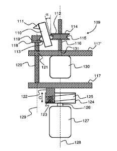
With reference to figure 20 there is shown a schematic illustration of the
functional principle of
a further embodiment of a launching mechanism according to the invention
generally indicated
by reference numeral 109 in figure 20. Contrary to the embodiments described
above, the
central shaft member 116 is not longitudinally displaceable along the
longitudinal axis 128 but
fixed to the structure of the apparatus. Fixed to the central shaft member 116
there is provided
a cylindrical inner guide member 114 provided with a circumferentially
extending guide recess
or groove 115 formed such that it corresponds to an inner extension 112
provided on the
retaining claw member 110, 111, 112, 113 that is configured to retain the
target on the
launching head (which will be described in detail below) during rotational
acceleration of the
launching head from approximately zero rotational speed to its terminal speed,
at which the
claw member releases the target from the launching head. An example of this
claw member is
shown in figure 26 below. The launching head including the inner guide member
is rotated by
the motor 130.
The rotational movement of the axle 126 of a second motor 127 is converted to
a longitudinal
displacement of the shaft or rod 120 by means of a first cylindrical member
124 fixedly mounted
on the axle 126 of the motor 127. In the first cylindrical member 124 there is
provided a
circumferential recess or groove 125 that is in engagement with a similarly
shaped guide
member 123 fixedly connected via member 122 to a laterally extending plate
member 117.
The recess or groove 125 is inclined relative to the longitudinal axis 128
such that when the
23
CA 03135533 2021-09-29
WO 2020/253923
PCT/DK2020/000086
first cylindrical member 124 rotates, the engagement between the recess or
groove 125 and
the guide member 123 causes the plate member 117 to move vertically (as seen
in the figure,
cf. arrow C) in the direction of the longitudinal axis 128. This movement is
transferred to an
outer guide member 118 that is a part of the launching head and that is
provided with a
circumferentially extending recess or groove 119 formed for engagement with an
outer
extension 113 formed on the retaining claw member 110, 111, 112, 113. The
longitudinal
movement of the outer guide member 118 thereby causes the retaining claw
member 110,
111, 112, 113 to pivot as indicated by the angle a between a state in which it
retains the target
to the launching head and a state in which it releases the target from the
launching head.
It is noted that a complementary configuration of the rotation-to-displacement
mechanism 122,
123, 124, 125 could alternatively be used. An embodiment of a complementary
rotation-to-
displacement mechanism is shown in figure 24c and will be described in
connection herewith.
With reference to figure 21 there is shown a schematic perspective and partly
sectional view
of the upper portion (i.e. the portion that contains the launching head upon
which the target is
placed) of an embodiment of a launching device according to the invention.
In figure 21, reference numeral 132 generally indicates the launching head
that comprises a
conical tubular section 133 formed to accommodate the inner space 8 of the hub
portion of the
target and a plane portion 134 upon which the target is placed, such that the
conical section
133 supports the inner space of the hub portion of the target. The launching
head is configured
to be able to rotate about the longitudinal axis 128 driven by the motor 130.
The inner guide member 114 is fixedly attached to the axle 136 of the motor
130 at a fixed
position along the rotational axis 128. The inner guide member 114 is as
described above
provided with a circumferentially extending guide recess or groove 115 in
engagement with an
inwardly extending protrusion 112 provided on the retaining claw member 110,
thereby
establishing a longitudinally (along axis 128) fixed hinge about which the
retaining claw
member 110 van pivot. Two positions of the retaining claw member are shown in
figure 21.
The launching head further comprises the body portion 133, 134, which portion
is configured
to undergo vertical movement (displacement along the rotational axis 128 in
the direction
indicated by arrow D. An inner circumferential wall portion of the body 133,
134 is provided
with a circumferentially extending recess or groove 119 formed for engagement
with a radially
outwardly extending protrusion 113 provided on the retaining claw member 110.
When the
body portion 113, 114 undergoes a displacement as indicated by arrow D, the
retaining claw
24
CA 03135533 2021-09-29
WO 2020/253923
PCT/DK2020/000086
member 110 will be forced to undergo a pivotal movement about the hinge
portion established
by the engagement between the guide recess or groove 115 that is in engagement
with the
inwardly extending protrusion 112 provided on the retaining claw member 110.
Thereby, a
longitudinal displacement along axis 128 of the body portion 133, 134 will be
converted into a
pivotal movement of the retaining claw member 110 between a state, in which it
retains the
target to the launching head and a state, in which the target can leave the
launching head and
commence its movement along a chosen trajectory in space.
The conical portion 133 of the launching head is provided with suitable
recesses or slits 135
through which the retaining claw members can pass. In the figures, three
retaining claw
members 110 are shown equally angularly distributed in the launching head, but
it is
understood that other numbers of retaining claw members could also be used.
The body portion 133, 134 must be able to undergo both longitudinal
displacement and to
rotate in unison with the inner guide member 114. This is in the shown
embodiment made
possible by connecting the body portion 133, 134 to the laterally extending
plate member 117
via a ball bearing 135 such that the body portion 133, 134 can rotate about
the rotational axis
128 relative to the plate member 117 and such that a displacement of the plate
member 117
in the vertical direction as indicated by arrow D will cause the body portion
133, 134 to undergo
a similar vertical displacement.
With reference to figure 22 the embodiment of the launching head and various
associated
functional means are shown in a perspective and partly exploded view. In
figures 21 and 22
identical elements are designated by the same reference numeral.
Figure 22 shows the outer guide member of the launching head generally
designated by
reference numeral 131 that on its outer surface comprises the conical portion
133 and the
plane portion 134. The conical portion 133 is provided with slits 135 that
accommodate a
portion of the retaining claw members. Figure 22 further shows the rotation
axle 136 of the
motor 130 that rotates the launching head and the inner guide member 114 with
its
circumferential recess or groove 115. One of the retaining claw members 110,
112, 113 is
shown in two positions hereof. The inner guide member 114 is positioned on top
of a cylindrical
body 137 that is provided with slits 138 for a portion of the retaining claw
members. The outer
guide member 131 is attached rotatably to the lateral plate member 117 via the
ball bearings
135 shown in figure 21, such that the outer guide member 131 can be displaced
longitudinally
by means of the lateral plate member 117 driven by the shaft member or rod
120.
CA 03135533 2021-09-29
WO 2020/253923
PCT/DK2020/000086
With reference to figure 23 there is shown a schematic, perspective and partly
exploded view
of an embodiment of a launching apparatus according to the invention generally
indicated by
reference numeral 139.
The apparatus according to this embodiment comprises basically a housing 147
with an
internal support structure upon which a number of rotatably mounted magazines
140 for
accommodating a plurality of targets according to the invention are provided.
The magazines
are provided with a suitable lid 141. The apparatus further comprises (in the
shown
embodiment) two separate launching devices 144 comprising the launching head
and
associated functional mechanisms that is described above. Each launching
device 144 is
io pivotally mounted on support members 145, such that a target can be
launched at a desired
angle relative to horizontal. The two launching devices 144 can be set to
different or identical
launching angles as desired.
The apparatus is configured such that a target (i.e. the lowermost target in a
given magazine)
is picked up by slidable/displaceable pickup means 143 and transferred to a
position
immediately above a receiving tray 146 on the upper longitudinal end of the
launching device
(cf. figure 24a). When a target is transferred from the magazine to the
receiving tray 146, the
launching device 144 is in a vertical position such that the target drops
downwards into the
receiving tray 146 by the effect of gravity. When the target is transferred to
the receiving tray,
and hence is correctly positioned on the launching head and locked to the
launching head by
the retaining claw members, the launching device is pivoted into its desired
angle, after which
the launching head and hence the target is accelerated from zero to the
desired terminal
rotational speed and when this is reached, the target is automatically
released from the
launching head. The apparatus according to the invention is provided with
sensor and control
means that determine if the desired terminal rotational speed is reached and
in this case
releases the target from the launching head when this speed is reached.
It is understood that the two launching devices during use can have different
elevation angles
and also that there may be provided other numbers of launching devices on the
apparatus that
the two shown in figure 23.
Corresponding to each separate launching device 144 there is provided a number
of
magazines or containers 140 that can accommodate a stack of targets. Prior or
during use,
these magazines 144 is filled with a sufficient number of targets. When a
given magazine 140
is empty, a succeeding magazine can be rotated about axis 142 in place for
providing targets
to the apparatus through a target providing mechanism that comprises the
receiving
26
CA 03135533 2021-09-29
WO 2020/253923
PCT/DK2020/000086
extendable tray member 143 that is configured to receive a target from the
magazine and bring
it into a position directly above a conically shaped receptor 146 mounted on a
launching head
provided at the upper longitudinal end (as seen in the figure) of the
launching device 144.
When the target is placed on the launching head it is rotated from zero
rotational speed to the
desired terminal rotational speed, at which it is released by the retaining
claw members. In the
shown apparatus, three such members are provided, but it is understood that
other numbers
of retaining claw members may be used.
With reference to figures 24a, 24b and 24c, a practical implementation of the
embodiment of
a launching device 144 according to the invention and specifically used in the
apparatus shown
.. in figure 23 is shown. Only a few of the details that are described in the
preceding figures are
indicated and these details/elements are designated be the same reference
numerals as used
in previous figures.
Figures 24a, 24b and 24c shows a launching device 144 according to an
embodiment of the
invention. Various drive means for the launching head 132 are accommodated
within the
.. cylindrical housing 144'. The launching head 132 is centrally located in
the tray member 146
that was described previously. The launching device 144 is supported by
support members
145 such that the launching device 144 can be pivoted about a lateral axis 150
relative to the
support members 145. This pivotal movement is obtained by means of a pivot
motor 148 via a
suitable functional connection, such as a belt or chain, generally indicated
by 149 (figure 24b).
The drive mechanism for the launching device 144 comprises three electrical
motors or similar
means: the drive motor 130 that rotates the launching head 132, the motor or
similar means
157 that opens/closes the retaining claw members via a rotation-to
displacement means 152,
154, 155, 156 described above and the pivot motor 148. Even though the term
"motor" is used
throughout this specification, it is understood that any kind of suitable
"actuator" means could
be used.
The housing 144' is attached to the inner structure of the launching device
144 via the tubular
members 151 shown in figure 24c.
On top (as seen in figures 24a and 24b) of the conical tubular section 133
there is provided a
closing cap member 133' that are also provided with slits for accommodating a
part of the
retaining claw members.
With reference to figure 25 there is shown a perspective view comprising the
launching head
and the lateral plate member 117 according to this embodiment of the
invention. Figure 25
shows the body portion of the launching head comprising the conical portion
133 that is formed
27
CA 03135533 2021-09-29
WO 2020/253923
PCT/DK2020/000086
for insertion into the inner space of the hub of the target and the planar
platform portion 134
upon which the target rests. Also shown are the inner guide member 114 with
the
circumferential groove 115 and the circumferentially extending recess or
groove 119 on the
inner wall portion of the outer guide member 133, 134. One of the retaining
claw members 110
is also shown. The body portion of the outer guide member 133, 134 is mounted
as described
above on the lateral plate member 117, such that the body portion of the outer
guide member
133, 134 can rotate and undergo longitudinal displacement as described above.
The plate
member 117 is displaced by means of the rod 120 as described above. The
longitudinally
extending rotational axis 128 is also indicated in figure 25.
With reference to figure 26(a) and 26(b) there are shown two specific designs
of the retaining
claw member 110that is used in the invention. It is understood that other
suitable designs
comprising similar main functional details could also be used.
The basic features of the retaining claw members according to the invention
are illustrated in
figure 26(a). The retaining claw member comprises an upper section I (as seen
in the figure)
.. and a lower section II separated by the line L connecting the center point
158 of the extension
112 that is in engagement with the circumferential groove 115 of the inner
guide member 114
with the center point 159', 159" of the extension 113 that is engagement with
the
circumferentially extending recess or groove 119 on the inner wall portion of
the outer guide
member 133, 134. The body of the retaining claw member is configured such that
the center
.. of gravity 160', 160" is located on this line. As it appears in figure
26(a), when the retaining
claw member is pivoted from the state in which the target is retained on the
launching head to
the state in which the target is released from the launching head, the center
of gravity moves
from the position indicated by 160' to the position indicated by 160". In the
latter state, the line
L forms an angle with the rotational axis 128 of substantially 90 degrees.
This configuration of
.. the retaining claw members minimizes the force required on the shaft member
or rod 120 and
provided by the motor 157 and hence facilitates release of the target from the
launching head
despite the powerful centrifugal forces acting on the retaining claw members
due to the very
high rotational speed of the launching head at the time of release of the
target.
Another geometrical configuration of the retaining claw member is shown in
figure 26(b). The
retaining claw member shown in figure 26(b) has the same basic features as
described above
in relation to figure 26(a). The main difference between the claw members
shown in figures
26(a) and 26(b) is the detailed shape of the claw portion 111 that retains the
target to the
launching head. It is however essential for any claw member configuration for
used according
to the present invention that those surfaces of the claw portions 111 that are
in contact with
28
CA 03135533 2021-09-29
WO 2020/253923
PCT/DK2020/000086
the target or can come in contact with the target during release of the target
from the launching
head have rounded corners (and not sharp corners) in order not to cause damage
to the target
during release, as even a minor damage to the target during release will be
likely to entirely
disintegrate the target due to the very high rotational speed of the target at
release.
In preferred embodiments of the retaining claw members according to the
invention, the
configuration of the claw members shown in figures 26a and 26b is such that
the following
apply (c.f. figure 26a, but similar principles apply to the claw member shown
in figure 26b):
The claw member (shown in two pivotal states) rotates about the rotational
axis R indicated by
reference numeral 128 and is pivotally mounted such that it can pivot about
the extension 112
(pivot point 158). When the opposite extension 113 is displaced longitudinally
as indicated by
arrow D from the lower longitudinal position 113' (in which the claw member
retains the target
to the launching head) to the upper longitudinal position 113" (in which the
claw member
releases the target from the launching head), the center of gravity 160 moves
from position
160' to the position 160", which is located on the line L extending from the
center 159 of the
outer extension 113 through the center of the inner extension 158 and forms an
angle p of
approximately 90 degrees to the longitudinal axis 128. Thereby, the section I
of the claw
member located above the center of gravity and the section II of the claw
member located
below the center of gravity are exposed to equal centrifugal forces, when the
launching head
rotates about the longitudinal axis 128. This configuration of the claw
members results in that
the force which must be transferred from the motor 157 via the shaft or rod
120 to the outer
extension 113 for releasing the target from the launching head is minimized.
With reference to figure 27 there is shown a schematic representation of a
portion of a
launching apparatus according to an embodiment of the invention illustrating
possible pivotal
and rotational movements of the launching devices of the apparatus.
The apparatus shown partly in figure 27 comprises two launching devices 144
mounted on a
surface P of the apparatus. On a portion P' of the respective launching device
144 the support
members 145 that allow pivotal movement of the launching devices (i.e.
changing the elevation
of the respective launching device) of the respective launching devices 144
are provided, such
that the portion P' and hence the support members 145 can rotate about the
axis 128 as
indicated by the angle 8. Hence, each launching device 144 can undergo a
combination of
rotation about the axis 128 that extends perpendicularly to the surface
portion P of the
apparatus and a pivotal movement changing the elevation angle y of the
respective launching
29
CA 03135533 2021-09-29
WO 2020/253923
PCT/DK2020/000086
device. By these means, each respective launching device can be brought to
different
launching directions relative to the apparatus.
With reference to figure 28 there is shown a schematic block diagram of a
control system
configured to control the main functions of the apparatus according to an
embodiment of the
.. invention. It is however understood that a control system for the apparatus
according to the
invention may comprise other functional units etc. than those shown in figure
28.
In the shown control system, the microcontroller 161 comprises the necessary
software
configured for receiving signals/instructions from a user or programmer that
sets up the control
system. Fixed/pre-programmed functions can be selected, and specific parameter
settings can
be chosen/adjusted by the user via a user control panel 164 provided on an
outer surface
portion of the apparatus. The user control panel communicates with the
microcontroller 161 as
indicated by c6 that commonly designates those control signals that are
provided from the user
control panel 164 to the microcontroller 161. It is furthermore possible for
the user to program
the control system from a dedicated user programming interface 165 that
preferably
communicates with the microcontroller 161 (c7) by means of wireless
communication (w11).
The microcontroller 161 provides control signals the the various functional
entities of the
apparatus. Thus, a control signal c1 is provided to a motor 168 that rotates
the magazines 140
when one of the magazines 140 is empty and a new need to be ready to transfer
targets to the
target receiving tray 143. Further, a control signal c2 controls the target
receiving tray to move
.. form a position in which it can receive a target from the magazine 140 that
is located above
the tray 143 to a position above the launching head 132 of the corresponding
launching device
144. A control signal c5 controls the elevation y of the launching device 144
and a control
signal c6 controls the azimuth 8 of the launching device 144. A control signal
c4 initiates the
release process of the target from the launching head 132. Initiation of the
release process
can be controlled by the user by means of for instance a pedal 166,167 that
may communicate
with the apparatus through a wireless connection w12. At c6 the
microcontroller 161 receives
information of the rotational speed of the launching head, based on which
information it
activated the release process.
The microcontroller 161 can, if desired, communicate with other apparatuses
according to the
invention via connection 168 by sending control signals c10 to other
apparatuses. Other
apparatuses can also communicate with the present apparatus via connection 168
thereby
forming a complete chain of interconnected apparatuses according to the
invention.
CA 03135533 2021-09-29
WO 2020/253923
PCT/DK2020/000086
It is understood that the control system of the apparatus according to the
invention may
comprise further features than those actually described above without
departing from the
scope of protection of the present invention.
The configuration of the launching apparatus according to the invention as
well as the
individual controllability of the launching devices as described above opens
up for a number
of interesting operational conditions of the apparatus that can be programmed
into appropriate
control systems provided in the apparatus either from the factory or/and
individually by the end
user of the apparatus.
Some of these possibilities are briefly outlined below relating to a specific
practical
.. implementation of the apparatus according to the invention:
- The apparatus shown in figures 23 and 27 can launch two targets
simultaneously or
with a delay of up to four seconds of the second target relative to the first
target.
- The launching speed of the targets is up to 120 km/h and the range is up
to 120 meters
depending on whether conditions.
- The targets rotate with a rotational speed of between 12000 rpm and 32000
rpm prior
to launching, which provides a very high directional stability of the targets.
- The apparatus will typically have eight fixed programs and up to an
additional eight
user defined programs.
- The apparatus is provided with a wireless user interface inter alia for
programming the
apparatus as well as a wireless foot pedal to release the target from the
apparatus.
- Launching can be delayed up to five seconds after the foot pedal is
activated in order
to give the shooter time to put on the gun before launching the target.
- If desired, the apparatus can launch up to four targets at different
speeds (and if desired
different launching directions relative to the apparatus), Thus, for instance
two targets
can initially be launched with a given (lower) launching speed followed by two
additional
targets launched at a higher launching speed, whereby the latter two catches
up with
the two first targets, when the targets enter the shooting area of the
shooter.
- A plurality of apparatuses according to the invention can be
interconnected such that a
flock of up to sixteen targets can be in the air together.
- The apparatus has a vertical range of approximately 125 to 150 meters such
that
shooting of migratory birds (such as geese) can be practiced.
- During user-programming of the apparatus, the different components of the
apparatus
moves in accordance with the programming, which greatly facilitates user-
programming of the apparatus.
31
CA 03135533 2021-09-29
WO 2020/253923
PCT/DK2020/000086
- The apparatus may be power supplied by batteries and can launch
approximately 5000
targets on a single charging.
- The magazines may typically accommodate up to 200 targets. Thus, the
plurality of
magazines on the shown embodiments can provide 400 targets before re-loading
of
the magazines becomes necessary.
- The magazines may accommodate any kinds of targets according to the
invention.
- The launching devices provided on the apparatus are basically completely
independent
entities. Thus, for instance, one launching device can launch a target while
the other is
loaded with a new target. This results in that the apparatus can launch
targets with two
seconds interval.
- The effective elevation range of the launching devices is from 0 degrees
(horizontal) to
90 degrees (vertical) and the effective azimuth range of the launching devices
is 160
degrees (+/- 80 degrees relative to the frontal direction from the apparatus).
At least two types of targets according to the invention is available: a
target for use at low wind
speeds (weight of target 6 grams) and targets for use at higher wind speeds
(weight of target
13 grams). The light targets affect the environment minimally and are also
cheaper than the
heavier targets. A preferred version of the targets of the invention are
reversible ("turnable")
which greatly facilitates loading of the targets into the magazines of the
apparatus. The targets
may be obtainable in 1000-piece packages, which saves packing and is
advantageous for the
environment.
32