Note: Descriptions are shown in the official language in which they were submitted.
WO 2020/236433
PCT/US2020/031884
TITLE OF INVENTION
SYSTEMS AND METHODS FOR REMOVING SPECIFIC IMPURITIES FROM FLUIDS
SUCH AS BLOOD USING A NANOTUBE SELECTOR
RELATED APPLICATIONS
The present application is related in subject matter to U.S. Patent Nos.
9,220,929 and
10,117,737, the entire contents of which are hereby incorporated herein by
reference.
FIELD OF THE DISCLOSURE
[0001] In U.S. Patent Not 9,220,929 and 10,117,737,
novel systems and methods were
disclosed by the present inventor for selectively removing selected impurities
from fluids,
including bodily fluids such as blood. In such systems and methods, impurities
may be
transported into the hollow interiors of arrays of nanotubes through
appropriately-sized pores
formed in the sidewalls of the nanotubes. The impurities so transported into
the interiors of the
nanotubes of the array may then be removed as a waste steam. When used to
purify blood, the
sidewall pores may be specifically sized to allow certain impurities in the
blood (typically small
to medium-sized molecules) to transport through the sidewall pores in the
nanotube walls, while
larger essential constituents of the blood that are not impurities, e.g. red
blood cells, are blocked.
As disclosed therein, such impurity transport may be assisted by applying
electric fields in the
vicinity of the nanotubes that may be oriented so as to assist in the
diffusion of selected
impurities across the sidewall pores and into the hollow interiors of the
nanotubes.
[0002] Building on these prior developments, in this
application, additional systems and
methods are disclosed that selectively transport specifically-sized impurities
present in a fluid
(e.g., blood) into the interiors of hollow nanotubes arranged in an array, so
that the impurities
may be readily separated from the fluid, thereby leaving the remaining fluid
in a purified
condition.
1
CA 03135659 2021- 10- 29
WO 2020/236433
PCT/US2020/031884
[0003] Accordingly, this disclosure provides
additional novel systems and methods for
removing undesirable impurities from a fluid, e.g., blood, by using the unique
properties of
ordered arrays of nanotubes such as, e.g., carbon nanotubes.
BACKGROUND
[0004] While the systems and methods disclosed herein
may be used to purify various
fluids, of specific interest and application is the use of such systems and
methods in an artificial
kidney capable of purifying blood.
[0005] In healthy humans and animals, the kidneys act
to purify the blood by effectively
removing excess water, salts, toxins, as well as breakdown materials and waste
products (e.g., as
produced by metabolism) that circulate in the blood.
[0006] Sometimes, however, the kidneys may fail to
operate effectively for a variety of
reasons, including various diseases. In individuals suffering kidney failure,
their kidneys do not
function properly and naturally produced waste products found in the blood
steam are not
effectively removed. As a consequence, about 600,000 people in the United
States of America,
and millions of people worldwide, suffer from kidney failure. This number has
been estimated
to be increasing at annual rates of about 9%.
[0007] Generally speaking, to restore such a patient
to close to full health, a kidney
transplant is needed. However, the demand for kidney transplants is heavily
outnumbered by the
limited supply of donor organs. For example, in 2017 there were about 100,000
patients in the
United States on waiting lists for a kidney transplant, while less than 20,000
kidney transplants
were performed that year.
[0008] Even with a kidney transplant, complications
such as host rejection and
complications from immunosuppressive medications, which may have to be taken
for life to
prevent rejection, are not uncommon. In addition, graft versus host and
transplanted infectious
diseases can also develop. As a consequence, in many patients with loss of
kidney function (e.g.,
renal failure), the normal cleaning process performed by the kidneys has to be
performed
2
CA 03135659 2021- 10- 29
WO 2020/236433
PCT/US2020/031884
artificially, for example, through external treatments such as dialysis,
typically either
hemodialysis or peritoneal dialysis.
[0009] In hemodialysis, a patient's blood is typically
re-routed outside the body to a
dialyzer which filters the blood using disposable cartridges that include
numerous substantially
small, semipermeable, plastic membranes, with varying pore sizes. As blood
diffuses through
the capillary system of the dialysis cartridge, contaminants are removed from
the patient's blood
in conjunction with a counter-current flow of a fresh dialysate solution.
Toxins in the blood
(e.g., salts and various unwanted low molecular weight molecules)
preferentially diffuse across
these membranes as a result of flow-induced or osmotic pressure differentials,
thereby reducing
toxin concentrations in the blood. The now-purified blood is then returned to
the patienfs body,
usually via a vein in the arm and/or through the lumen of an inserted
catheter.
[0010] However, this type of dialysis procedure has
many drawbacks. In order to
undergo dialysis, patients have to be connected for considerable amounts of
time to large and
expensive machines. Patients may typically be required to receive dialysis
treatments at least
three to four times a week, for about three to five hours at a time. Even with
such extensive and
frequent treatments, dialysis machines may only be about 13% as effective as a
fully functional
kidney. Unfortunately, the five-year survival rate of patients on dialysis has
been estimated to be
just 33-35%.
[0011] Further, the ability of the dialysis treatment
to remove large molecular mass
molecules, called middle molecular weight molecules, merely by diffusion
across a membrane is
very inefficient. When using dialysis, only about 10-40% of such larger
molecules may be
removed during a given dialysis session. This can lead to a buildup of larger-
sized toxins within
the patienfs blood. Consequently, without removal, these toxins can reach
abnormally high
concentration levels and can damage the body over time. Some have speculated
that inefficient
removal of these toxins represents a significant limitation of current renal
dialysis technology.
[0012] To achieve adequate removal of these toxins,
manufacturers and nephrologists
have been attempting to increase the surface areas of dialysis membranes and
to also prolong
dialysis treatment times. However, there are practical limits to increasing
the surface areas of
3
CA 03135659 2021- 10- 29
WO 2020/236433
PCT/US2020/031884
dialysis membranes. In addition, increasing the dialysis treatment times adds
to the detrimental
physical and social side effects of dialysis, by reducing the patient's
quality of life and adding to
the expense of treatment for people suffering from loss of kidney function.
100131 To overcome these deficiencies, the present
invention builds on advances in
nanotube fabrication technology to provide novel and efficient approaches for
removing
undesirable impurities, including the aforementioned toxins, that may be
present in a fluid such
as blood.
100141 By way of background, the fabrication of carbon
nanotubes has been extensively
studied in recent years, because they have unique physical and chemical
properties that are
useful in many applications. Technologies have been developed to efficiently
manufacture
various types of nanotubes and nanotube arrays. For example, it is now
possible to fabricate both
single-walled and multi-walled carbon nanotubes using various chemical vapor
deposition
(CVD) fabrication methods, among other techniques. Significantly, by
controlling the process
parameters and growth environments, vertically aligned "forests" or arrays of
carbon nanotubes
can be grown on a substrate for use in various applications and devices.
180151 Appropriate growth conditions and techniques
for growing such vertically aligned
carbon nanotube arrays have been described in various publications. By way of
example, and
without limitation, such publications include: (1) "Nickel Overlayers Modify
Precursor Gases
To Pattern Forests of Carbon Nanotubes," J. Phys. Chem. C 2017.121:11765-
11772, R. Yemini,
A. Itzhak, Y. Gofer, T. Sharabani, M. Drela, G.D. Nessim; (2) 'Differential
preheating of
hydrocarbon decomposition and water vapor formation shows that single ring
aromatic
hydrocarbons enhance vertically aligned carbon nanotubes growth," Carbon, 109
(2016) 727-
736, E Teblum, A. Itzhak, E. Shawat Avraham, M. Muallem, it Yemini, G.D.
Nessim; (3)
'Patterning of Forests of Carbon Nanotubes (CNTs) Using Copper Overlayers as
Iron Catalyst
Deactivators," I Phys. Chem. C. 120 (2016) 12242-12248, It Yemini, M. Muallem,
T.
Sharabani, E. Teblum, Y. Gofer, GD. Nessim; (4) 'Millimeter-Tall Carpets of
Vertically
Aligned Crystalline Carbon Nanotubes Synthesized on Copper Substrates for
Electrical
Applications," J. Phys. Chem. C. 118 (2014) 19345-19355, E. Teblum, M. Noked,
J. Grinblat,
A. Kremen, M. Muallem, Y. Fleger, et al., and (5) "Properties, synthesis, and
growth
4
CA 03135659 2021- 10- 29
WO 2020/236433
PCT/US2020/031884
mechanisms of carbon nanotubes with special focus on thermal chemical vapor
deposition,"
Nanoscale. 2(2010) 1306-1323, Gilbert D. Nessim. The contents of these
publications are also
incorporated herein by reference.
BRIEF DESCRIPTION OF DRAWINGS
[0016] The features and advantages of the present
disclosure will be more fully
understood with reference to the following description, when taken in
conjunction with the
accompanying figures, wherein:
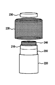
[0017] FIG. 1 illustratively depicts an assembly view
of an exemplary embodiment of a
cylindrical carbon nanotube selector.
[0018] FIG. 2 illustratively depicts a cross-sectional
view of the FIG. 1 exemplary
embodiment, taken through the center of the cylinder.
[0019] FIG.3A illustrates an exploded view of a carbon
nanotube selector showing one
example of how it may be arranged in a housing.
[0020] FIG. 3B shows the arrangement of FIG. 3A, after
assembly.
[0021] FIG. 4A illustrates an exploded view of a
second embodiment showing an
assembly of multiple carbon nanotube selectors.
[0022] FIG. 4B illustrates a cutaway view of the
assembled second embodiment of FIG.
4A.
DETAILED DESCRIPTION
[0023] The following detailed description is directed
to novel systems and methods for
removing impurities from fluids such as, for example, blood, by using arrays
of aligned hollow
nanotubes, e.g., carbon nanotubes, arranged to selectively remove certain
impurities from a fluid.
CA 03135659 2021- 10- 29
WO 2020/236433
PCT/US2020/031884
[0024] In particular, the nanotubes may be
manufactured to have a hollow interior that
is dimensioned to selectively permit impurities with a smaller dimension to
pass through, while
larger-sized constituents of the fluid are blocked from passing through. Such
selective removal
of impurities based on size is very useful for purifying blood, since
typically the impurities that
are removed, e.g., by conventional dialysis techniques, are smaller than the
key constituent of
the blood, e.g., red blood cells.
[0025] As described herein, several novel approaches
and configurations are disclosed
for fabricating such nanotube selectors using arrays of aligned nanotubes that
may be fabricated
from carbon or other materials.
[0026] In exemplary embodiments, the inner diameters
of the nanotubes in the nanotube
selector can range from about lnm (e.g., for single wall semipermeable
nanotubes) to about
several nanometers (e.g., for multi-wall semipermeable nanotubes). For
example, the inner
diameter of typical multi-wall hollow nanotubes that are currently available
is in the range of
about 2 to 6 nanometers (mu). Such diameters are of the same order of
magnitude as the size of
most single molecules. Comparatively, a single red blood cell has a diameter
of about 7,000 urn,
while a typical virus measures only about 100 nm in diameter.
[0027] In exemplary embodiments, the nanotubes have
generally cylindrical shapes that
can be several microns to one or more millimeters long with aspect ratios
(e.g., length to
diameter ratio) in excess of 10,000 or more.
[0028] As described in the foregoing references
identified herein and known in the art,
anays of vertically aligned nanotubes, e.g., carbon nanotubes are generally
grown on flat non-
porous substrates that would block the flow of fluids through their hollow
interiors. Therefore,
to make the hollow interiors of a vertically aligned nanotube array accessible
to a fluid
undergoing purification, the vertically aligned nanotube array may be removed
from the
substrate after growth and supported on a substrate, so as to provide for
fluid flow through the
hollow nanotube interiors.
6
CA 03135659 2021- 10- 29
WO 2020/236433
PCT/US2020/031884
100291 For example, after growth of the aligned
nanotubes, they may be transferred to or
otherwise supported by a fluid impermeable support material, so as to leaving
their ends open to
fluid transport As one fabrication example, the spaces between the nanotubes
may be sealed
by, e.g., infiltrating a polymer material between the spaces to form a fluid
impermeable polymer
support matrix that supports and maintains the alignment of the nanotubes.
1011301
Plasma oxidation or other etching
processes may be thereafter be employed to
remove the original substrate on which the vertically aligned nanotubes were
grown, so as to
expose the open ends of the hollow nanotubes that were originally attached to
the substrate.
When this processing is completed, the nanotubes will be supported in the
support material, but
the ends of the nanotubes will be open and accessible for transport of fluids
containing impurities
and the like, through the hollow nanotubes, from one side of the support
material to the other
side.
100311 By using a material, such as flexible polymer
matrix, to support the vertically
aligned nanotube array, the resulting structure may be wrapped into a
cylindrical configuration,
generally shown by refctence numeral 200 in FIG. 1. As evident the nanotube
array 200 that
was generally aligned to a substrate during the growth process, when
cylindrically wrapped, will
have it nanotubes generally oriented in a radial direction with respect to the
center of the
cylinder. This is illustrated by the cross-sectional view of FIG. 2 where the
diffusion direction
depicted by the arrow is in the radially inward direction towards the center
of the cylinder, which
is on the right side of FIG.2.
100321 Reverting back to FIG. 1, to provide further
structural support for the cylindrical
array of now generally radially aligned hollow nanotubes, the layer 200 may be
sandwiched
between an inner fabric layer 210 and an outer fabric layer 220, both of which
may be
electrically insulating and sufficiently porous to readily permit impurities
that may be present in
a fluid circulating in a fast space outside the cylindrical assembly to pass
through the fabric
layers 210 and 220, and flow through the hollow interiors of the nanotubes in
layer 200 into a
second space internal to the cylindrical assembly.
7
CA 03135659 2021- 10- 29
WO 2020/236433
PCT/US2020/031884
100331 In addition to providing a porous support for
the cylindrical nanotube layer 200,
by incorporating inner and outer fabric layers 210,220 that are electrical
insulators, these layers
210, 220 may also act to electrically insulate the nanotube layer 200, which
would be electrically
conductive in the case where the nanotube layer 200 is made from carbon-based
nanotubes.
100341 By way of example, and without limitation, many
suitable electrically insulating
porous fabrics may be used, such as fiberglass insulation cloth or 171TE
fabric (Teflon ), to
name but several examples.
100351 As further shown in the exemplary embodiment of
HG.!, an inner cylindrical
metallic mesh 240 is positioned radially interior to the inner cylindrical
fabric layer 210, and an
outer metallic mesh 230 is positioned to surround the outer fabric layer 220.
These metallic
meshes, 230, 240 act as further supporting members for the intervening layers
210,200 and 220
and provide conductive surfaces that are electrically insulated from the
nanotubes by the fabric
layers 210, 220.
100361 Accordingly, an electrical voltage may be
applied between the inner and outer
mashes 230,240 to provide an electric field therebetween that can assist in
the transport of
impurities through the hollow interiors of the nanotube layer 200, in which
the nanotubes are
generally aligned in a radial direction perpendicular to the cylinder axis.
100371 The electric field may be generated by an
appropriate electrical voltage source to
which the metallic meshes 230, 240 are connected by conductive leads (e.g.,
leads 380, 390
shown in FIG. 3A and discussed below).
100381 A partial cross-sectional view of the FIG. 1
cylindrical nanotube selector
assembly is shown in FIG. 2, with the cylindrical outside of the selector
assembly being depicted
on the left-hand side of FIG.2. As shown in the FIG. 2 cross-sectional view of
the FIG.1
embodiment, the nanotube array 200 comprises nanotubes 202 that are supported
by a support
structure 204, such that the ends of the nanotubes are open to receive fluid
containing impurities
that may be circulating in a first outer space surrounding the cylindrical
nanotube selector and
permit them to be transported through the hollow nanotubes into a second
interior space formed,
8
CA 03135659 2021- 10- 29
WO 2020/236433
PCT/US2020/031884
at least in part by the inner portion of the hollow cylinder, where they may
be collected for
removal.
[0039] Thus, in FIG. 2, impurities present in a fluid
that is introduced in a first space
surrounding the outside of the nanotube selector assembly will diffuse (in a
diffusion direction
depicted by the arrow in FIG. 2) through the nanotubes and the various layers
of the nanotube
selector into a second space formed at least in part by the interior of the
cylindrical nanotube
selector.
[0040] In operation a fluid containing impurities may
flow inwardly through the outer
mesh 230 and through the relatively large pores in the fabric 220. Impurities
in the fluid having
sizes that are less than the inner dimensions of the hollow nanotubes, will
continue to flow and
diffuse into the hollow interiors of the nanotubes in the nanotube layer 200.
For example, when
fabricated, if the fluid to be purified is blood, the interior lumens of the
hollow nanotubes can be
dimensioned to pass water and other impurities, while red blood cells and
other constituents of
the blood, whose dimensions are too large to pass through the interiors of the
nanotubes, will be
excluded.
[0041] In the exemplary embodiment of FIG. 2, upon
exiting the nanotube layer 200, the
fluid, including impurities with dimensions small enough to pass through the
hollow nanotube
interiors, will continue to diffuse through the inner fabric 210 and through
the inner mesh 240
into the interior space of the nanotube selector assembly, where it may be
collected to form a
waste stream for removal.
[0042] As shown in FIG. 2, conductive leads 380,390
may be respectively connected to
the outer metal mesh 230 and inner metal mesh 240. A voltage source (not
shown) can be
applied across leads 380 and 390 to generate an electric field for selectively
enhancing the
diffusion of charged impurities across the nanotube selector assembly.
[0043] Referring back to FIG. 1, to complete the
nanotube selector assembly, a cap 250
may be positioned on one end of the cylinder so as to cover the interior oldie
cylinder. The cap
250 prevents fluid in the outer space from entering directly into the interior
space of the cylinder,
9
CA 03135659 2021- 10- 29
WO 2020/236433
PCT/US2020/031884
thereby insuring that only impurity-laden fluid that is transported through
the hollow nanotubes
will enter the interior space. In addition, once the impurity-laden fluid is
within the interior
space, the cap 250 prevents such fluid from escaping through the top of the
cylinder so that it can
be collected and/or removed in a waste stream.
[0044] In accordance with this exemplary embodiment,
fluid that has entered into the
interior space of the cylinder is an impurity-laden fluid that has traversed
the hollow interiors of
the nanotubes in the nanotube layer 200. Such fluid can either be collected by
a collection
system, e.g., a system including a receptacle placed at the bottom of the
interior space of the
cylindrical nanotube selector, or may be further channeled to a collection
system that includes a
waste outlet port for collection as a waste stream.
[0045] For example, when the nanotube selector
assembly is used as part of an
implantable artificial kidney system to purify blood, the impurity-laden fluid
could be channeled
into a waste stream that would be passed to the body's ureter for excretion
through a surgically
fabricated structure, as generally discussed and illustrated in U.S. Patent
No. 9,220,929.
100461 As should be evident to workers of skill in the
art, once impurities are transported
into the interior space of the nanotube selector, the flow of the fluid and
the electrical field that
may be generated in the vicinity of the nanotube selector will make it
improbable for such
impurities to diffime back in the opposite direction, thereby resulting in
separation of the
impurities in the fluid.
[0047] The nanotube selector assembly described above,
may be assembled into a
housing, as shown in the exploded view of FIG. 34, where like components are
labelled with the
same reference numerals used in FIG. 1. As shown in FIG. 3A, the components of
the nanotube
selector may be assembled and enclosed by a housing having a cylindrical
portion with a fluid
outlet port 310, a top portion 320 having a fluid inlet port 330, and a bottom
portion 350 in
which the impurities that pass though the nanotube selector may be collected.
FIG. 313 shows a
fully assembled view in which electrode wires 380 and 390, which in operation
would be
connected to a voltage source, are arranged to pass through the housing for
respective
connections to the outer and inner metal meshes 230, 240.
CA 03135659 2021- 10- 29
WO 2020/236433
PCT/US2020/031884
[0048] When assembled as shown in FIG. 3B, fluid to be
purified may flow into the
container at the top through the fluid inlet port 330 and out through the
outlet port 310. As
evident, fluid leaving the outlet port 310 may be recirculated back to the
inlet port 330 in
multiple passes and be further purified during each pass through the selector.
In each such pass,
impurity-laden fluid that passes through the hollow radially-arranged
nanotubes in the nanotube
layer and into the center of the selector may be collected in the bottom
portion 350 of the
housing or diverted into a waste stream.
[0049] To increase the efficiency of impurity
separation and removal, multiple nanotube
selectors may be operated in parallel, as shown in the exemplary embodiment of
FIGS. 44, B,
where FIG. 4A shows an exploded view and FIG. 4B shows an assembled view.
[0050] With reference to FIG. 4A, multiple nanotube
selectors 405a, 405b, and 405c may
be assembled into a common housing. Note that in the exemplary FIGS. 44, B
embodiment, the
three nanotube selectors 405a, 405b, and 405c are shown to have a domed cap,
but are otherwise
may each be constructed in substantially the same manner as shown in FIG.1.
Although three
selectors are shown, it is contemplated that many such selectors may be
arranged to operate in
parallel
[0051] As further shown in FIG. 4A, each cylindrical
nanotube selector is mounted in a
mounting interface portion 406 that allows only impurity-laden fluid that has
passed through the
nanotube selector and into its inner space to communicate with a collection
system such as
receptacle 407.
[0052] As discussed above with respect to FIG. 1, each
nanotube selector 405a, 405b,
and 405c includes a radially-arranged array of hollow nanotubes that permits
fluid and impurities
that are sufficiently small, to flow through the hollow interiors of the
nanotubes and into the
cylindrical interior space of the nanotube selector, from which the impurity-
laded fluid may enter
the collection system, such as receptacle 407.
[0053] As shown in FIGS. 44, B, fluid to be purified
may enter through an inlet port 401
into a common enclosure 402. The fluid exits through outlet port 408.
11
CA 03135659 2021- 10- 29
WO 2020/236433
PCT/US2020/031884
[0054] Only impurity-laden fluid that passes through
the hollow nanotube array in each
of the nanotube selectors 405a, 405b, and 405c enters the common collection
system, e.g.,
receptacle 407, from where it may be removed.
[0055] Although, the exemplary embodiment of FIGS. 4A,
B shows the impurity-laden
fluid being collected in a common collection receptacle 407, the common
receptacle may be part
of a collection system that may be configured to include a waste outlet port
from which the
in purity-laden fluid may be removed as a waste stream.
[0056] Still further, it is also contemplated that the
fluid leaving outlet port 408 may be
recirculated through appropriate piping and fittings for reentry back into the
inlet port 401, so
that additional purification of the fluid may occur as the fluid is
recirculated through the
nanotube selectors in multiple passes. Since a substantially large number of
purification passes
can be readily implemented by recirculation of the fluid, each single pass may
only be required
to remove a small amount of impurities.
[0057] When the nanotube selector assemblies are used
as an artificial kidney, following
the purification process, purified blood and contained plasma can be rerouted
and/or returned to
the patient
[0058] As in the FIG.1 embodiment each of the nanotube
selectors may have electrodes
(not shown in FIGS. 4A, B) attached to the inner and outer metallic meshes and
to a voltage
source to provide an electric field across the nanotube selector to enhance
the diffusion of
impurities through the nanotube selector.
[0059] It will be understood by those of ordinary
skill in that art that the disclosed
systems and methods can be used for separating and removing impurities,
including charged
impurities, and filtering impurities from any type of fluid such as, but not
limited to, water,
aqueous solutions, non-aqueous solutions, precious material recovery systems,
wastewater
processing, blood, cerebrospinal fluid, bile, and bio-fluids.
12
CA 03135659 2021- 10- 29
WO 2020/236433
PCT/US2020/031884
[0060] While in a preferred embodiment, the fluid
being filtered and/or purified is blood,
the foregoing descriptions are in no way meant to be a limitation on the types
of fluids that can
be purified using the disclosed systems and methods.
[0061] Further, when used as artificial kidney
system, the nanotubes and/or other
materials may be finictionalized with specifically selected surfactants and/or
anticoagulants
selected to prevent blood that contacts their surfaces from coagulating or
clotting.
[0062] As used herein, "functionalized" (or any
version thereof) refers to surface
treatments by which specific atomic molecular groups may be attached to alter
the specific
properties of the nanotubes or structures described herein.
[0063] Functionalization can be generally performed by
various surface modification
techniques such as wet chemistry, or vapor, gas, and/or plasma chemistry, and
microwave
assisted chemical techniques, to name a few. These techniques utilize surface
chemistry to bond
desirable materials to surfaces of carbon nanotubes.
[0064] When the exemplary embodiments are used in an
artificial kidney system,
polymers, anticoagulants, and/or other selected molecules may be attached to
surfaces oldie
nanotubes and/or other parts of the assembly.
[0065] Anticoagulant molecules (e.g., similar to
Heparin or Hirudin) may also be
covalently linked to the nanotubes using such known techniques. Once so
attached, these
anticoagulant molecules help to substantially prevent the blood from clotting.
[0066] Further, in exemplary embodiments, the nanotube
selector assembly can be fitted
to utilize sensors designed to detect the presence of certain impurities. This
would allow, for
example, the ability to measure concentrations of selected charged species
within the incoming
blood and/or within the already purified blood and/or within the waste stream,
or as may be
desired from any combination of these locations. Such sensors may include, by
way of example,
impurities-specific sensors, ion-specific electrochemical sensors,
spectroscopic type sensors,
which can communicate signals to suitable microcontrollers.
13
CA 03135659 2021- 10- 29
WO 2020/236433
PCT/US2020/031884
[0067] Such sensors can measure concentrations of
selected charged species in either the
incoming fluid (before filtration) and/or the outgoing fluid (after
filtration). This information,
when coupled to appropriate feedback mechanisms, allows regulation of applied
potentials
across the nanotube selector.
[0068] By way of example, the general types of sensors
that can be utilized may include,
but are not limited to, sensors that can rapidly detect multiple species such
as, but not limited to,
Na+ (aqueous) and K+ (aqueous).
[0069] Further, the sensors can be designed to
communicate their information to a
microprocessor for evaluation and response. By way of example, the nanotube
selector assembly
can utilize such sensors, microprocessors, and/or other devices to control
and/or provide
feedback by utilizing technologies similar to those used with, for example,
pacemakers and
spinal cord stimulators.
[0070] While carbon-based nanotubes have been widely
studied to date and are available
in various configurations, it is further contemplated that the foregoing
systems and methods may
be use nanotube arrays formed from other materials, and should not be
understood as being
limited to carbon-based nanotube arrays.
[0071] Now that exemplary embodiments of the present
disclosure have been shown and
described in detail, various modifications and improvements thereon will
become readily
apparent to those skilled in the art, all of which are intended to be covered
by the following
14
CA 03135659 2021- 10- 29