Note: Descriptions are shown in the official language in which they were submitted.
CA 03135819 2021-10-01
System for a presentation, sales or exhibition stand and/or for shopfittinq
[0001] The present invention relates to a system or presentation
system, in par-
ticular for a presentation, sales or exhibition stand and/or for store
fitting, a current-carry-
ing wall member as well as a current collector for an electrical device. The
proposed
presentation system may also be used in museums or in the field of smart home.
[0002] A presentation or exhibition stand is the first point of
contact for a new
customer and therefore particularly important as a figurehead for the company
presenting
itself. For this reason, the visual impression and also the options for
different and in partic-
ular flexible presentations are increasingly important. As a special eye-
catcher on wall,
floor or ceiling members of presentation, exhibition or sales stands, but also
in shop-fitting,
special electrical devices such as lighting equipment or monitors etc. are
increasingly
used to direct the viewer's attention to certain elements. However, in the
state of the art
the arrangement of such lighting equipment or generally electrical devices
requires electri-
cal wiring, which greatly limits the flexibility regarding a variable
arrangement of the elec-
trical device or lighting equipment. In the same way, an attractive
presentation is of in-
creasing importance in store fitting.
[0003] DE 102011 005 735 Al discloses a system for a presentation,
sales or
exhibition stand and/or for store fitting comprising at least one wall, floor
or ceiling mem-
ber having a carrier material and a cover covering the same, wherein
electrical conductor
tracks are provided on the carrier material or arranged on/in the cover and
wherein the
carrier material and/or the electrical conductor tracks can be magnetized,
i.e. have ferro-
magnetic properties; and comprising at least one electrical device which can
be attached
to the carrier material by means of at least one magnet, wherein the
electrical device com-
prises needle-shaped current collectors which penetrate the cover when the
electrical load
is attached to the carrier material and thereby make electrical contact with
the conductor
tracks and supply the electrical device with current.
[0004] The system known from DE 10 2011 005 735 Al makes it possible to
provide a wall member, for example for a presentation, sales or exhibition
stand or for
Date Recue/Date Received 2021-10-01
CA 03135819 2021-10-01
2
store fitting, which in particular enables an easily changeable and therefore
flexible ar-
rangement of electrical devices on the wall member.
[0005] DE 10 2018 115 659 B4 discloses a system for a presentation,
sales or
exhibition stand and/or for store fitting, the system comprising a current-
carrying wall
member and a current collector for an electrical device, which is configured
to be mounted
on the wall member; wherein the wall member comprises a carrier plate and a
cover that
covers the carrier place; wherein the wall member comprises first electrical
conductor
tracks of a first polarity and second electrical conductor tracks of a second
polarity,
wherein the first and second electrical conductor tracks are arranged
alternately at least in
sections; wherein the current collector comprises a plurality of at least
three contact nee-
dles, wherein the current collector is adapted to be attached to the wall
member such that
at least one of the contact needles contacts one of the first electrical
conductor tracks and
at least another of the contact needles contacts one of the second electrical
conductor
tracks; and wherein a first contact needle, a second contact needle, and a
third contact
needle of said plurality of contact needles are arranged on a circle.
DE 10 2018 115 659 B4 further discloses a respective current collector.
(0006] The solution described in DE 10 2018 115 659 B4 is intended
to enable
a freely selectable and flexibly variable positioning of an electrical
consumer on a wall
member in a simple manner.
[0007] Against this background, it is an object of the present
disclosure to pro-
vide a further improved system for a presentation, sales or exhibition stand
and/or for
store fitting.
[00081 According to a first aspect of the present disclosure, a
system, in particu-
lar for a presentation, sales or exhibition stand and/or for store fitting, is
proposed, the
system comprising:
a mounting rail assembly comprising one or more current carrying
mounting rails;
Date Recue/Date Received 2021-10-01
CA 03135819 2021-10-01
3
a current-carrying wall member, which is configured to be mounted on
the mounting rail assembly; and
a current collector for an electrical device, which is configured to be
mounted on the wall member;
wherein the wall member comprises a carrier plate having a front side
and a back side;
wherein the wall member comprises first electrical conductor tracks (of a
first polarity) and second electrical conductor tracks (of a second polarity),
wherein the
first and second electrical conductor tracks are arranged alternately at least
in sections;
wherein the first electrical conductor tracks and the second electrical
conductor tracks are
arranged on the front side of the carrier plate;
wherein the current collector comprises a plurality of at least two contact
needles, wherein the current collector is adapted to be attached to the wail
member such
that at least one of the contact needles contacts one of the first electrical
conductor tracks
and at least one other of the contact needles contacts one of the second
electrical con-
ductor tracks;
wherein the wall member comprises a first electrical terminal contact and
a second electrical terminal contact, wherein the first electrical terminal
contact is electri-
cally conductively coupled to the first electrical conductor tracks, wherein
the second elec-
trical terminal contact is electrically conductively coupled to the second
electrical conduc-
tor tracks, and wherein the first electrical terminal contact and the second
electrical termi-
nal contact are arranged on the back side of the carrier plate; and
wherein the current-carrying mounting rail assembly (500) is adapted to
hold and supply power to the wall member (10) via the first electrical
terminal contact and
the second electrical terminal contact..
[0009] It shall be understood that the current collector or an
electrical device
with such a current collector may be sold separately. According to a further
aspect, a cor-
responding base system is thus proposed without the current collector.
However, the sys-
tem is adapted to interact with the current collector.
Date Recue/Date Received 2021-10-01
CA 03135819 2021-10-01
4
[0010] According to a further aspect of the present disclosure, a
corresponding
wall member (for use) in a system for a presentation, sales or exhibition
stand and/or for
store fitting is proposed.
[0011] According to a further aspect of the present disclosure, the
use of such a
wall member in such a system is proposed for a presentation, sales or
exhibition stand
and/or for store fitting.
[0012] According to a further aspect, a corresponding method of
manufacturing
a corresponding wall member for a system for a presentation, sales or
exhibition stand
and/or for store fitting.
[0013] According to a further aspect, a method for a presentation,
sales or exhi-
bition stand and/or for store fitting for a system as described above is
proposed.
[0014] The inventors recognized that the handling of current-
carrying wall ele-
ments in shopfitting is a new kind of challenge for the employees involved. In
previous
systems, there is often a separation between the tasks of a designer or
decorator and the
subsequent supply of electrical energy. It would thus be desirable to also
make it easier
for designers and decorators to deal with current carrying (live) wail
members. Further-
more, it would be desirable to reduce the time required to design or redesign
a shop win-
dow. This is particularly true in view of the fact that shop windows are often
re-modelled
outside normal opening hours, including at night or at weekends. Moreover, it
would be
desirable to provide a system that requires only a reduced installation space,
since shop
window space in good locations is expensive. Furthermore, it would be
desirable if access
is only required from a front side of a display window wall. This would allow
a shop win-
dow to be redesigned independently of the shop space behind it
[0015] According to the present disclosure, it is thus proposed to
provide a wall
member comprising a carrier plate having a front side and a back side; wherein
the wall
member comprises first electrical conductor tracks of a first polarity and
second electrical
conductor tracks of a second polarity. The first and second electrical
conductor tracks can
Date Recue/Date Received 2021-10-01
CA 03135819 2021-10-01
at least in sections be arranged alternately. The first electrical conductor
tracks and the
second electrical conductor tracks are arranged on the front side of the
carrier plate. The
first electrical conductor tracks are electrically conductively coupled with
each other. The
second electrical conductor tracks are electrically conductively coupled with
each other.
The wall member further comprises a first electrical terminal contact and a
second electri-
cal terminal contact. The first electrical terminal contact is electrically
conductively coupled
to the first electrical conductor tracks. The second electrical terminal
contact is electrically
conductively coupled to the second electrical conductor tracks. The first
electrical terminal
contact and the second electrical terminal contact are arranged on the back
side of the
carrier plate. Further measures are explained below by way of example.
[0016] The power supply may be provided by a mounting rail
arrangement com-
prising one or more current carrying mounting rails. Hereby, the current
carrying wall
member may be configured to be mounted on the mounting rail arrangement or to
one or
more of its mounting rails. Furthermore, the current-carrying mounting rail
assembly may
be arranged to supply current (power) to the wall member via the first
electrical terminal
contact and the second electrical terminal contact . The use of current-
carrying mounting
rails in the specific application scenario of supplying wall members as
described above
has not been known before. The inventors recognized that, in particular by
means of the
first and second terminal contacts arranged on the back side of the carrier
plate, both the
fastening and the power supply can be provided via the a mounting rail
assembly.
[0017] So instead of direct wiring of electrical devices at a
presentation, sales
or exhibition stand, a multi-level system is provided. The power supply, e.g.
from a DC
voltage source with no more than 40V, is provided (1) via the mounting rail
assembly (2)
to the wall member and (3) further via the current collector to (4) the
electrical device.
[0018] The proposed solution is based on the general idea that a
current-carry-
ing wall serves as the source and an adapter or current collector is provided
to tap elec-
tricity from the wall. The wall member can be adapted to be connected to a
current or volt-
age source such as a power supply. Advantageously, however, the power supply
is pro-
vided via a current carrying mounting rail arrangement which is adapted to
hold the wall
member on the one hand and to supply current to the wall member on the other
hand via
Date Recue/Date Received 2021-10-01
CA 03135819 2021-10-01
6
the first electrical terminal contact and the second electrical terminal
contact on the back
side of the carrier plate. The first electrical tracks can be connected to a
positive pole, in
particular provided by the mounting rail arrangement, via the first backside
electrical termi-
nal contact and the second tracks to a negative pole, in particular provided
by the mount-
ing rail arrangement, via the second backside electrical terminal contact. For
example, a
DC voltage of 12V or 24V can be provided. Alternatively, a different type of
power supply,
such as an AC voltage or a DC voltage with a superimposed AC voltage can be
provided
via the first and second electrical terminal contacts. The wall member can
have a carrier
plate and optionally a cover that covers it. The combination of carrier plate
and cover is
especially advantageous for such presentation stands, because a cover can be
changed
quickly and the stand can be easily adapted. The cover may extend over a wall
member
or a group of wall members. For example, such a cover can be printed and/or
labeled.
The current collector and/or the electrical device can be adapted to be
mounted on or at-
tached to the wall member.
[0019] The conductor tracks of the electrical wall member can be an
integral
part of the carrier element, for example in the form of a punched steel plate,
and can be
arranged on the carrier material and/or on or in the cover. it shall be
understood that a
wall member may also have a layered structure. Such a layered structure can
have one or
more of the following layers: a support structure, such as wood or metal, a
layer of a mag-
netic or magnetizable material, such as steel, an insulation layer, and a
conductor track
layer, e.g. of a (thin) metal foil. For example, a carrier plate or support
structure, e.g. made
of plastic, may be provided, on which a layer of a magnetic or magnetizable
material, e.g.
steel, is applied, which may optionally be adapted as a first and/or second
conductor track
at the same time, and optionally a cover can be provided. The use of a layer
of a magnetic
or ferromagnetic material is advantageous, because a current collector or
consumer can
be flexibly attached to the wall member with magnets. Advantageously, the
first and sec-
ond backside terminal contacts may be part of the layer structure of the wall
member.
(0020] The current collector comprises a plurality of at least two
or at least three
contact needles, for example exactly two. The current collector is adapted to
be mounted
on the wall member in such a way that at least one of the contact needles
contacts one of
the first electrical tracks and at least one other of the contact needles
contacts one of the
Date Recue/Date Received 2021-10-01
CA 03135819 2021-10-01
7
second electrical tracks. For example, in the case where the conductive tracks
are ar-
ranged on the carrier plate of the wall member and the wall member has a cover
that co-
vers the carrier plate, the contact needles may be adapted to penetrate the
cover and
make an electrical connection with the respective conductive tracks. The
contact needles
can pierce through or into the wall member. It is also possible that the
electrical conduc-
tors are integrated into the cover, in particular woven into it. In this case,
first electrical
conductor tracks of the cover may be connected to the first back-side terminal
contact and
second electrical conductor tracks of the cover may be connected to the second
back-side
terminal contact. The cover may optionally be considered part of the wall
member. Basi-
cally, the current collector can be adapted to establish an electrical
connection with the
first and the second conductor track when placed on the wall member and to
supply the
tapped voltage to a consumer or load device.
[0021] Advantages of the proposed solution in comparison to
conventional
store or trade fair construction may in particular that a complex cabling of
the individual
electrical devices attached to the presentation element can be omitted.
Instead, the con-
sumer devices can be flexibly attached to the presentation element on-the-fly.
Expensive
corrections can thus be omitted. In addition, creativity can be promoted,
since the individ-
ual consumers can be flexibly repositioned and aligned, especially also with
regard to their
rotation relative to the wall member. In a way, such a system invites to play
and experi-
ment with the arrangement of the electrical consumer devices in order to
achieve the most
appealing presentation result. In particular, the current-carrying wall member
can be
charged with electricity even before the consumers are attached and the result
can be as-
sessed immediately. A time-consuming new wiring is not necessary.
[0022] It is to be understood that the current collector can either
be attached as
such to the wall member and the tapped current can, for example in a wired
manner, be
fed to a consumer device, or the current collector can be integrated into a
holder or inte-
grated in an electrical consumer device.
[0023] Further advantages can arise in the next system level due to
the system
approach comprising wall members and current-carrying mounting rails. A
problem in
Date Recue/Date Received 2021-10-01
CA 03135819 2021-10-01
8
shop fitting is that display window areas have very different sizes and
geometries. Adapt-
ing wall members to different shop windows is time-consuming and expensive.
With the
proposed system approach, standardized wall members can be used. For example,
the
wall members can be configured as a kind of tiles with a limited size, e.g.
with edge
lengths of 30 cm x 30 cm or 50 cm x 50 cm or 25 cm x 50 cm. The installation
of a large
number of wall members or separate mounts would generally require a lot of
effort. How-
ever, because the wall members are adapted to be mounted to a mounting rail
assembly
and also adapted to be supplied with power by the same, the installation
effort can be sig-
nificantly reduced. The mounting rails can be easily attached to a back wall
of a shop win-
dow, for example by means of screws and dowels, adhesive joints, etc. The
mounting rails
are supplied with power and passed on to the wall members via the backside
contacts,
without the need for additional wiring. This also allows easy redecorating of
store windows
without having to rely on an electrician. After the wall members have been
arranged on
the current-carrying mounting rail assembly, they can be provided with a
cover, as already
described above.
[0024] In particular, the mounting rail assembly can comprise a
plurality of
mounting rails which are adapted such that a plurality of current-carrying
wall members
can be mounted thereon without gaps. It shall be understood that tolerances of
a few milli-
meters to a few centimeters may occur in shop fitting.
[0025] A system for a presentation, sales or exhibition stand
and/or for store fit-
ting can also be referred to as a display or show stand. A wall member in the
context of
the present disclosure can also refer to a floor element or a ceiling element.
in the context
of the present disclosure, a contact needle can also refer to a contact pin or
contact stick,
which does not necessarily have a pointed tip. The contact needles can be
arranged in
such a way that these or the tips or ends of the contact needles lie in one
plane. Option-
ally, the contact needles can be spring-loaded. The contact needles can be
adapted to
penetrate the cover. In the context of the present disclosure, an equilateral
or equilateral
triangle can optionally be understood to be a triangle in which the lengths of
the legs or
sides do not differ by more than 20%, preferably by more than 10%, preferably
by more
than 5% each relative to one of the other legs or sides. A mounting rail
assembly may
Date Recue/Date Received 2021-10-01
CA 03135819 2021-10-01
9
comprise one or more mounting rails. A mounting rail may also be referred to
as a support
rail, an anchor rail or a retaining rail. For example, it may be a top hat
rail or keyhole rail.
[0026] In an embodiment, an extension of the first electrical
conductor tracks
can be guided around a (frist) edge of the carrier plate from the front side
to the back side
of the carrier plate and can be electrically conductively coupled to the first
connection con-
tact. An extension of the second electrical conductor tracks can be guided
around a (sec-
ond) edge of the carrier plate from the front side to the back side of the
carrier plate and
can be electrically conductively coupled to the second connection contact. An
advantage
of this embodiment may be a simple low-cost manufacturing.
[0027] The first electrical conductor tracks and the second
electrical conductor
tracks can form an interlining/engaging comb structure. The first electrical
conductor
tracks can form a first comb and the second electrical conductor tracks can
form a second
comb, wherein for at least one of the two combs the prongs of the comb
structure are ar-
ranged on the front side of the carrier plate and a web of the comb structure
connecting
the prongs is arranged on the back side of the carrier plate. An advantage of
this solution
can be a more flexible positioning of the current collector, in particular in
edge regions. By
arranging the connecting web of the comb structure on the back side, the
current collector
can also be flexibly positioned in the edge regions of the wall member.
[0028] The electrical conductor tracks on the front side and the
electrical termi-
nal contacts on the back side can comprise a common electrically conductive
layer. The
electrically conductive layer is guided or wrapped around an edge of the
carrier plate from
the front side of the carrier plate to the back side of the carrier plate. In
other words, the
first electrical conductor tracks and the first electrical terminal contact on
the back side
may comprise a common electrically conductive layer. The second electrical
conductor
tracks and the second electrical terminal contact on the back side may
comprise a com-
mon electrically conductive layer. It shall be understood that there is no
electrically con-
ductive link between the first and second electrical conductor tracks,
otherwise a short cir-
cuit may occur. The common electrically conductive layer, may thus comprise
two sub-re-
gions insulated from each other, a first sub-region of the first polarity and
a second sub-
region of the second polarity, wherein the first sub-region comprises the
first electrical
Date Recue/Date Received 2021-10-01
CA 03135819 2021-10-01
conductor tracks and the first electrical terminal contact, and the second sub-
region com-
prises the second electrical conductor tracks and the second electrical
terminal contact.
An advantage of this solution may be simple, low-cost production. An advantage
may be
that contact problems may be reduced.
[0029] In a refinement, the electrical conductive tracks on the
front side and the
electrical terminal contacts on the back side can comprise a common
electrically conduc-
tive foil which is applied to the carrier plate. The first and second
conductive tracks may
thus be provided using a common electrically conductive foil during
manufacturing by pat-
terning the foil. An advantage may be a simple, low-cost production. It shall
be understood
that such a foil may optionally comprise further layers, or that a plurality
of foils may be
provided one above the other. For example, in the case of a carrier plate made
of steel or
another conductive material, an insulating layer may be provided between the
carrier plate
and an electrically conductive layer of the foil.
[0030] The first and the second electrical terminal contacts may be
arranged ro-
tationally symmetrically on the back side of the carrier plate. This can
facilitate positioning.
For example, a rotation of 180* may be possible. The electrical connection can
thus be
established at different rotation states. Alternatively or additionally, the
first and the sec-
ond electrical terminal contact can be arranged mirror-symmetrically on the
back of the
carrier plate. In addition or in the alternative, the first and second
electrical terminal con-
tacts can be arranged mirror-symmetrically on the back side of the carrier
plate.
[0031] The first and second electrical terminal contacts can be
arranged at di-
agonally opposite corners on the back side of the carrier plate. A corner-side
arrangement
on the back side preferably allows contact with further adjacent carrier
plates to be estab-
lished in an efficient manner.
[0032] The wall member can further comprise a third electrical
terminal contact
and a fourth electrical terminal contact. The third electrical terminal
contact can be electri-
cally conductively coupled to the first electrical conductor tracks. The
fourth electrical ter-
minal contact can be electrically conductively coupled to the second
electrical conductor
Date Recue/Date Received 2021-10-01
CA 03135819 2021-10-01
11
tracks. The third electrical terminal contact and the fourth electrical
terminal contact can
be arranged on the back side of the carrier plate. In particular, four
electrical terminal con-
tacts may thus be provided on the back side of the carrier plate. These may be
arranged
rotationally symmetrically by 900.
[0033] The wall member can be square. This can simplify the
handling of the
wall members, in particular in conjunction with four, preferably 90'
rotationally symmetri-
cally arranged terminal contacts, since such wall members may be applied
independent of
the orientation (in 900 steps).
[0034] The first electrical terminal contact can be arranged in a
first edge region
on the back side of the carrier plate. The second electrical terminal contact
can be ar-
ranged in a second, preferably opposite edge region on the back side of the
carrier plate.
An advantage of this embodiment may be that less material may be necessary.
This ap-
plies in particular it the back side terminal contacts are connected to the
respective front-
side conductor tracks via extension of the front-side conductor tracks.
[0035] The first electrical terminal contact can extends along a
first edge of the
back side of the carrier plate. The second electrical terminal contact can
extends along a
second, opposite edge of the back side of the carrier plate. For example, the
first and/or
second connection contact may extend along at least 50%, in particular along
at least
75%, in particular along at least 85%, in particular along at least 95% of an
edge. This
may improve a durability of the wall members, in particular when a common
electrically
conductive foil is used. A further advantage may be that fewer cuts are
required during
manufacturing, and thus manufacturing may be simplified.
[0036] The first and second electrical terminal contacts on the
back side can be
coupled by electrical connections through the carrier plate to the respective
corresponding
electrical conductor track on the front side. An advantage of this embodiment
may be that
electrically insulating edges of the carrier plates can be provided.
Date Recue/Date Received 2021-10-01
CA 03135819 2021-10-01
12
[0037] The system can comprise a cover covering the front side of
the carrier
plate. The cover may be configured to cover one or more carrier plates
simultaneously. A
plurality of carrier plates may be surrounded by a common frame to which the
cover may
be attached. This may enable easy replacement of the cover.
[0038] The wall member and the current collector can be adapted
such that the
current collector can be magnetically attached to the wall member. This
enables easy and
quick attachment. For example, a designer can try out different positions on
the wall mem-
ber.
(0039] The system can comprise a plurality of at least two, in
particular at least
four, in particular at least nine of the wall members. The system can further
comprise an
electrode arrangement for supplying power to the wall members via the first
and second
connection contacts on the back side. The electrode arrangement may optionally
be con-
figured to supply power to the back of the wall members via the first and
second terminal
contacts, and at the same time serve to attach the wall members to a wall.
(0040] In a refinement, the electrode arrangement can comprise a
first group
and a second group of electrodes. Said first group of electrodes can be
adapted and ar-
ranged to connect said first electrical terminal contacts of said respective
wall members to
a first polarity. Said second group of electrodes can be adapted and arranged
to connect
said second electrical terminal contacts of the respective wall members to a
second polar-
ity. For example, the electrodes of the first group and the electrodes of the
second group
may be arranged in different rows and/or columns, in particular arranged in a
checker-
board pattern.
(0041] The electrode arrangement can further be adapted such that
the wall
members are magnetically attachable to the electrode arrangement. In
particular can the
electrode arrangement comprise electrically conducting magnets. An advantage
of this
embodiment may be that the magnetic attachment of the wall members
simultaneously
provides a power supply to the wall members.
Date Recue/Date Received 2021-10-01
CA 03135819 2021-10-01
13
[0042] The system can comprises a plurality of at least two, in
particular of at
least four, in particular of at least nine of the wall members. Advantageously
at least two
of the plurality of the wall members are arranged on a common mounting rail of
the
mounting rail arrangement (and are supplied with power via the mounting rail
arrange-
ment. This facilitates the installation and allows to flexibly equip display
windows of differ-
ent sizes.
[0043] The (current-carrying) mounting rail assembly and the
(current-carrying)
wall member can be adapted such that the wall member is hooked or hookable
into the
mounting rail assembly and/or the wall member is clamped or clampeable to the
mounting
rail assembly. This allows easy installation. The current-carrying mounting
rail assembly
and the current-carrying wall member can be adapted such that, upon hooking
and/or
clamping the wall member, an electrically conductive connection is established
between
the current-carrying mounting rail assembly and the current-carrying wall
member.
Thereby the power supply can be provided in an easy way. The power wiring is
simplified.
In particular there is no need for additional process steps for separate
wiring.
[0044] The walk member can comprise, on the back side of the
carrier plate, at
least one retaining element which is adapted to hook the wall member into the
mounting
rail assembly and/or to attach the wall member to the mounting rail assembly
(500) in a
clamping manner. Thereby the wall members can be installed on the mounting
rail assem-
bly in a time-efficient mariner.
[0045] The mounting rail assembly can comprise one or more mounting
rails
comprising a plurality of recesses. The wall member can be adapted to be
attached to the
mounting rail assembly by engaging with one or more of the recesses. For
example, a re-
taining element on the back side of the carrier plate may be suitably
arranged. The plural-
ity of recesses allows flexible arrangement of the wall members at different
positions
along the mounting rails. In particular, an electrically conductive connection
between the
current-carrying mounting rail arrangement and the current-carrying wall
member can be
established simultaneously.
Date Recue/Date Received 2021-10-01
CA 03135819 2021-10-01
14
[0046] In a refinement, the mounting rail assembly can comprises
one or more
keyhole rails and wherein the wall member can be adapted to be attached to the
mounting
rail assembly by engaging in one or more apertures of the keyhole rails.
[0047] At least one retaining element on the back side of the
carrier plate can
be adapted to engage in one of the recesses and in particular to latch
therein. For exam-
ple, the retaining element can formed as a pin with a mushroom head. Such a
pin with a
mushroom-like-shaped head may, for example when the mounting rail is
configured as a
keyhole rail, be configured to be inserted into the wide opening area of one
of the keyhole-
shaped recesses of the keyhole rail and then to be pushed into the narrower
area of the
keyhole-shaped recesses. This allows for quick assembly while providing a more
secure
attachment. Generally, the mounting rail assembly and the wall member may be
arranged
such that the wall member may be inserted into the mounting rail assembly.
Improved re-
tention and increased security is particularly advantageous in public areas.
[0048] The system can further comprise an interlock for locking the
wall mem-
ber to the mounting rail assembly. For example, in the case of a keyhole rail,
the wide
opening of the keyhole-shaped recess may be closed with a locking device in
the form of
a plug and thus prevent the wall member from slipping out.
[0049] The mounting rail assembly can comprise a top-hat rail or
rail having a
C- or G-shaped profile, and the wall member can be adapted to be engagingly
and/or
ciampingly attached to the mounting rail assembly. Generally various types of
mounting
rails may be used. However, by using standardized profiles in this new system,
the manu-
facturing costs can be reduced.
[0050] The mounting rail assembly may comprise a first conductor of
the first
polarity, the first conductor of the mounting rail assembly and the first
electrical terminal
contact being arranged on the back side of the carrier plate such that an
electrical contact
is established when the current carrying wall member is attached to the
current carrying
mounting rail assembly. The mounting rail assembly may further comprise a
second con-
ductor of the second polarity, wherein the second conductor of the mounting
rail assembly
Date Recue/Date Received 2021-10-01
CA 03135819 2021-10-01
and the second electrical terminal contact are arranged on the back side of
the carrier
plate such that electrical contact is made when the current carrying wall
member is at-
tached to the current carrying mounting rail assembly.
[0051] The current-carrying mounting rail assembly can comprises a
first con-
ductor of the first polarity (first current phase e.g. positive polarity) and
a second conduc-
tor of the second polarity (second current phase e.g. negative polarity). For
example, the
mounting rail may be made of plastic or other non-conductive material. The
respective
conductive tracks may then be provided on the mounting rail. The first
terminal contact of
the backing plate may be arranged and configured to tap current from the first
conductive
track. The second terminal contact of the carrier plate may be arranged and
adapted to
tap current from the first conductor track. in this case, both poles may thus
be provided
with only one mounting rail.
[0052] However, it is also possible that the current-carrying
mounting rail as-
sembly comprises at least one first mounting rail for providing the first
polarity (first current
phase, e.g. positive pole) and at least one second mounting rail for providing
the second
polarity (second current phase, e.g. negative pole). In particular, the first
and/or second
attachment rail may be electrically conductive. For example, the first and/or
second
mounting rail may be metal rails. An advantage of this solution may be that no
separate
conductive tracks need to be applied. A low-cost electrically conductive metal
rail may be
used.
[0053] The first and/or second electrical terminal contact on the
backside of the
carrier plate can comprise a contact spring for electrically contacting the
current-carrying
mounting rail. For example, an extension of the electrical conductive tracks
may be guided
from the front side to the back side of the carrier plate and a contact spring
may be pro-
vided there, which taps current from the mounting rail. For example, a contact
spring may
be applied to the extension of the electrical conductor track in an
electrically conductive
manner, for example via a conductive adhesive connection or soldering or
welding.
Date Recue/Date Received 2021-10-01
CA 03135819 2021-10-01
16
[0054] A retaining element for securing the wall member to the
mounting rail ar-
rangement may be arranged separately from the first and second electrical
terminal con-
tacts on the back side of the carrier plate. In an embodiment, the retaining
element does
not have an electrically conductive connection to one or both of the
electrical terminal con-
tacts. As described above, the electrical conductive tracks on the front side
and the elec-
trical terminal contacts on the back side may comprise a common electrically
conductive
layer. The electrically conductive layer can be guided around an edge of the
carrier plate
from the front side of the carrier plate to the back side of the carrier
plate.. In this case, it
may be helpful if the retaining element does not at the same time form an
electrical termi-
nal contact, since the layer structure may cause any of the underlying
(insulating) layers to
detach when the retaining element is mechanically stressed. A separately
arranged retain-
ing element, which advantageously is directly attached to the carrier plate,
may thus pro-
vide improved mechanical stability. For example, the retaining element can be
attached to
the carrier plate by an electrically insulating adhesive. This can reduce a
risk of short cir-
cuits or fault currents in the event that one of the electrical conductors
unintentionally es-
tablishes an electrical connection with the carrier plate.
[0055] In an embodiment, the wall member can comprise at least a
first and a
second retaining element on the back side of the carrier plate. The mounting
rail assembly
can comprise at least a first and a second mounting rail. The arrangement can
be adapted
such that the first retaining element is adapted and arranged to be fastened
to said first
mounting rail. Accordingly, the second retaining element is adapted and
arranged to be
fastened to the second mounting rail.
[0056] In a refinement, the first and second retaining elements can
be arranged
rotationally symmetrically or mirror symmetrically on the back side of the
carrier plate. This
can facilitate the assembly. Since the power is first supplied via the
mounting rails and the
current collector is adapted to handle currents of different polarity (since
its position and
contacting of the respective conductor tracks is not known in advance), an
arrangement in
different rotational orientations is generally uncomplicated. It shall be
understood that fur-
ther retaining elements, for example a third and fourth retaining element, may
optionally
be provided. In one embodiment, the retaining elements are arranged in the
corners of the
wall member.
Date Recue/Date Received 2021-10-01
CA 03135819 2021-10-01
17
[0057] Optionally, the wall member may comprises exactly two
retaining ele-
ments. The first retaining element can be arranged at a first side or in a
first edge region
on the back side of the carrier plate. The second retaining element can be
arranged in a
second opposite side or edge region on the back side of the carrier plate. For
example on
a left and right side. A first spacer can be arranged in the edge region of
the first retaining
element on the rear side of the carrier plate. A second spacer can be arranged
in the edge
region of the second retaining element on the back side of the carrier plate.
The spacers
can be configured to provide a defined spacing between the back side of the
carrier plate
and the respective first and second mounting rails. The defined spacing can
advanta-
geously corresponds to that spacing which is established by the first and/or
second retain-
ing element between the back side of the carrier plate and the respective
first and second
fastening rails. Thereby, for example tilting can be avoided. As a spacer, a
distance ele-
ment or spacer can for example be glued on.
[0058] The mounting rail can comprise a plurality of recesses,
wherein the re-
cesses are arranged in a regularly spaced manner, and a length of the wall
member cor-
responds to an integer multiple of a distance between two recesses of the
mounting rail.
For example, a wall member may have an edge length of 500 mm and the recesses
may
be arranged with a hole spacing of 50 mm (center-to-center spacing). An
advantage may
be that adjacent wall members may be arranged side by side or one above the
other
along the mounting rail substantially without a gap.
[0059] The first electrically conductive tracks and the second
electrically con-
ductive tracks on the front side of the carrier plate of the wall member may
lie in the same
plane.
[0060] Optionally, the system may comprise two types of wall
members. A first
type of wall member as described above with electrical conductor tracks, an a
second
type of wall member without front side conductor tracks. In general, the
system can com-
prise at least one wall member without front side conductor tracks. An
advantage of this
embodiment can be that certain areas of a display window, in which electrical
consumers
are to be attached, can be equipped with the more complex wall members
comprising the
electrical conductors in a targeted manner. However, in the other areas, less
expensive
Date Recue/Date Received 2021-10-01
CA 03135819 2021-10-01
18
wall members without such electrical conductors may be provided. In other
words, the
system may include a first wall member or group of wall members with front
side conduc-
tor tracks and a second wall member or group of wall members without front
side conduc-
tor tracks. Optionally, a wall member without front side conductor tracks may
have a back
side electrical insulation. The electrical insulation may be provided at least
in an area
where contact with an electrode for power supply could occur, in particular to
avoid electri-
cal connection to one or more electrodes of the electrode arrangement.
[0061] According to a further aspect of the present disclosure, a
method of
manufacturing a wall member for an aforementioned system is provided, the
method com-
prising the steps:
providing (ferromagnetic) a carrier plate, wherein the carrier plate has a
front side and a back side;
applying first electrical conductor tracks of a first polarity and second
electrical conductor tracks of a second polarity, wherein the first and second
electrical
conductor tracks are arranged alternately at least in sections; wherein the
first electrical
conductor tracks and the second electrical conductor tracks are applied on the
front side
of the carrier plate;
applying a first electrical terminal contact and a second electrical termi-
nal contact on the back side of the carrier plate, wherein the first
electrical terminal contact
is electrically conductively coupled to the first electrical conductor tracks,
and wherein the
second electrical terminal contact is electrically conductively coupled to the
second electri-
cal conductor tracks.
[0062] In particular, the method may comprise the step of:
providing an electri-
cally conductive foil, having a first electrically conductive region
comprising the first electri-
cal conductor tracks and the first terminal contact, and having a second
electrically con-
ductive region comprising the second electrical conductor tracks and the
second terminal
contact. The electrically conductive foil can then be applied to the carrier
plate such that
the electrical conductor tracks of the first and second polarity are provided
on the front
side, and the first and second connection contacts are provided on the back
side.
Date Recue/Date Received 2021-10-01
CA 03135819 2021-10-01
19
[0063] According to a further aspect of the present disclosure, a
system, in par-
ticular for a presentation, sales or exhibition stand and/or for store
fitting, is proposed, the
system comprising:
a current-carrying wall member and
a current collector for an electrical device (electrical consumer device),
which is configured to be mounted on the wall member;
wherein the wall member comprises a carrier plate and a cover (cover-
ing) that covers the carrier plate;
wherein the wall member comprises first electrical conductor tracks (of a
first polarity) and second electrical conductor tracks (of a second polarity),
wherein the
first and second electrical conductor tracks are arranged alternately at least
in sections;
wherein the current collector comprises a plurality of at least three con-
tact needles,
wherein the current collector is adapted to be attached to the wall mem-
ber such that at least one of the contact needles contacts one of the first
electrical con-
ductor tracks and at least one other of the contact needles contacts one of
the second
electrical conductor tracks; and
wherein a first contact needle, a second contact needle, and a third con-
tact needle of said plurality of contact needles are arranged on a circle.
Features accord-
ing to this further aspect may advantageously be combined with features of the
wall mem-
ber with the backside contacting as described above.
[0064] According to a further aspect of the present disclosure, a
corresponding
current collector for an electrical consumer (for use) in a system for a
presentation, sales
or exhibition stand and/or for store fitting is proposed.
[0065] According to a further aspect of the present disclosure, the
use of such a
current collector in such a system is proposed for a presentation, sales or
exhibition stand
and/or for store fitting.
[0066] According to a further aspect, a corresponding method is
proposed for or
for the equipping of a presentation, sales or exhibition stand and/or for
store fitting.
Date Recue/Date Received 2021-10-01
CA 03135819 2021-10-01
[0067] The solution disclosed in DE 10 2011 005 735 Al enables a
substan-
tially free positioning in a horizontal and vertical direction on current-
carrying wall member.
However, with conventional needle connectors, there is the problem that the
rotation of
the current collector relative to the current-carrying wall member can cause
both contact
needles to come to rest on the same electrical conductor track. For example, a
current
collector or an electrical consumer comprising a current collector cannot
simply be rotated
by 90. It would thus be desirable to further improve the positionability and
to still establish
an electrical contact even with different angular orientations.
[0068] Optionally, the current collector may not only comprise two
contact nee-
dles but a plurality of at least three contact needles, wherein a first
contact needle, a sec-
ond contact needle, and a third contact needle of the plurality of contact
needles are ar-
ranged in such a way that they lie on a circle or arc of a circle. Due to the
proposed ar-
rangement of the contact needles on a circle arc, in addition to a relatively
free position-
ing, e.g. in horizontal and/or vertical direction, an additional degree of
freedom can be cre-
ated, which can enable a freer rotation.
[0069] Thereby, the probability that at least one of the contact
needles contacts
one of the first electrical tracks and at least one other of the contact
needles contacts one
of the second electrical tracks can be increased. In other words, the contact
of at least two
contact needles with the respective tracks of different polarity can be
maintained longer
upon rotation. Further measures to enable a substantially free rotation are
explained in the
examples below.
[0070] Alternatively or in addition to the above arrangement of the
first, second
and third contact needles, the first, second and third contact needles may be
arranged in
such a way that a first straight line through the first and second contact
needles and a
second straight line through the second and third contact needles intersect at
an (acute)
angle.
[0071] The first, second and third contact needle of the current
collector can be
arranged in such a way that they form a triangle, in particular an acute-
angled triangle. An
Date Recue/Date Received 2021-10-01
CA 03135819 2021-10-01
21
acute-angled triangle is a triangle in which all angles are smaller than 90 .
The three sides
can, but do not have to be of different lengths.
(0072] In an embodiment, the first, the second and the third
contact needle of
the current collector can be arranged in such a way that they form an
isosceles, in particu-
lar an equilateral triangle.
(0073] A triangular arrangement of the first, second and third
contact needles
lying on the circle or circular arc, in particular for an arrangement as an
approximately
equilateral triangle, may allow a more flexible positioning, in particular
with regard to a ro-
tation of the current collector on the wall member.
[0074] In an embodiment, a diameter of the circle on which the
first contact
needle, the second contact needle and the third contact needle are located can
be smaller
than or equal to the sum of a width of one of the first conductor tracks and a
width of one
(adjacent) of the second conductor tracks, and optionally a gap between them.
An ad-
vantage of this solution may be that when the current collector is rotated,
different contact
needles on the first or second conductor track come to rest on and enable
contact of at
least two contact needles on different conductor tracks over a larger angular
range.
[0075] In an embodiment, the contact needles of the current
collector can be
arranged in such a way that, when the current collector is attached to the
current-carrying
wall member, at least a first of the contact needles (lying on the circle) can
be brought into
contact with one of the first conductor tracks and a second contact needle
(lying on the
circle) can be brought into contact with one of the second conductor tracks,
independently
of a rotation (or alignment) of the current collector (in the plane of the
circle or plane of the
wall member) on the current-carrying wall member. It shall be understood that
the contact-
ing may not to be understood completely independent of rotation, but within
the scope of
the present disclosure as substantially independent of rotation, e.g. taking
into account a
tolerance of +-5 or +-ICY', so that a contact needle does not fall in a gap
between two ad-
jacent conductor tracks. Such a gap may be provided to avoid a short circuit
between two
adjacent conductor tracks.
Date Recue/Date Received 2021-10-01
CA 03135819 2021-10-01
22
[0076] In other words, the contact needles of the current collector
can prefera-
bly be arranged in such a way that, independently of a rotation of the current
collector on
the wall, at least one of the contact needles makes a connection with one of
the first con-
ductor tracks (e.g. the positive pole) and at least one other of the contact
needles makes a
connection with one of the second conductor tracks (e.g. the negative pole).
Thus, an
electrical power supply of a device via the proposed current collector can be
made possi-
ble over a wide angular range.
[0077] In an embodiment, the contact needles lying on a circle can
be arranged
in such a way that the first contact needle lies in a first third of the
circle, the second con-
tact needle lies in a second third of the circle and the third contact needle
lies in a third
third of the circle. For example, the circle can be divided into three circle
segments of
equal size and one of the three contact needles can be located in each of the
three circle
segments.
[0078] In an embodiment, the current collector may further comprise
a fourth,
fifth and sixth contact needle. The first to sixth contact needle can be
arranged as a hexa-
gon. In particular, the contact needles can be arranged as a hexagon, in
particular as an
equilateral hexagon or star, with the contact needles forming the corners of
the hexagon
or the tips of the star respectively. However, it shall be understood, that a
different number
of contact electrodes may be provided, in particular four or more, five or
more, six or
more, seven or more, or eight or more.
[0079] In an embodiment, the current collector and the contact
needles may be
arranged such that, when the current collector is attached to the wall member,
at least two
contact needles contact one or more of the first electrical conductor tracks
and at least
two of the contact needles contact one or more of the second electrical
conductor tracks.
This can be particularly advantageous for applications with high power
consumption. Usu-
ally a current collector with 3 or 4 contact needles is sufficient for
currents up to 2A. How-
ever, a higher number of contact needles can be advantageous as the current
per current
collector can be reduced. For example, cheaper components may be used. For
example,
two standard diodes each for 2A may be cheaper than a high-power diode
designed for
4A. Alternatively, several current collectors can be used in parallel to tap a
required
Date Recue/Date Received 2021-10-01
CA 03135819 2021-10-01
23
power. Experiments have shown that besides the supply of lamps also the supply
of dis-
plays is feasible. With a combination, such as a parallel connection of
several current col-
lectors, outputs of up to 3,000 watts or more are generally feasible.
[0080] In an embodiment, the contact needles can be arranged such
that a dis-
tance between the first contact needle and a straight line through the second
contact nee-
dle and the third contact needle is greater than a width of one of the
electrical conductor
tracks. In the alternative or in addition, a distance between the first
contact needle and a
straight line through the second contact needle and the third contact needle
can be
smaller than twice the width of one of the electrical conductor tracks, and
optionally an in-
sulation gap between them. An advantage of this arrangement may be that
rotation is pos-
sible over a wide angular range.
[0081] In an embodiment, the current collector may comprise a
fourth contact
needle and the fourth contact needle may be arranged within the circle on
which the first,
the second and the third contact needles are arranged. For example, the fourth
contact
needle may be arranged on a center of a circle or on a center of a triangle
formed by the
first, second and third contact needles. An advantage of this embodiment can
be that it
further improves the probability of enabling a sufficient electrical
connection of the current
collector to the conductors. For example, the problem that two of the three
contact nee-
dles lying on the circle may fall into an insulation gap between one of the
first tracks and
one of the second tracks can be addressed. In an advantageous refinement, the
fourth
contact needle can be arranged decentered at a distance from a center of the
circle. It
shall be understood that also the features of this embodiment can be combined
with the
features of one or more of the previous or following embodiments. A "fourth"
contact nee-
dle can be understood as a further contact needle. For example, a fourth
contact needle in
the above mentioned arrangement as a hexagon can be understood as a first
fourth con-
tact needle and a fourth contact needle which is arranged within the circle
according to the
present example can be understood as a second fourth contact needle or further
contact
needle. It shall be understood that this second fourth contact needle or
further contact
needles can be arranged within a circle on which the first, second and third
contact nee-
dles are arranged, but on which also further contact needles can be arranged.
Date Recue/Date Received 2021-10-01
CA 03135819 2021-10-01
24
[0082] In an embodiment, the system may also comprise a rectifier.
The recti-
fier may be adapted to provide an output voltage of defined polarity based on
an input
voltage applied to at least two of the contact needles. The rectifier can be
part of the cur-
rent collector, a separate element or part of the electrical device. For
example, a bridge
rectifier can be provided. In addition or in the alternative, the rectifier
can be arranged in a
device that can be connected to the current collector. The rectifier may
comprise a first
output contact and a second output contact. In order to limit the complexity
of the circuitry
and thus the costs of the rectifier, the current collector may preferably
comprise exactly
four or exactly three contact or exactly two contact needles. In particular
with exactly four
contact needles an advantage is the limited circuit complexity and the
possibility to cover
large angle ranges.
[0083] In a further refinement, the rectifier may have at least
three inputs and
(exactly) two outputs, whereby each of the at least three inputs is connected
to a respec-
tive contact needle.
[0084] In an embodiment, the current collector (optionally in
combination with a
holder) can be adapted such that the contact needles are movable between a
contact po-
sition, in which the contact needles contact the conductive electrical tracks,
and a non-
contact position, in which the contact needles are separated from the tracks
when the cur-
rent collector is attached to the current-carrying wall member. Here the non-
contact posi-
tion can also be called a shifting position or moving position. Preferably,
the current collec-
tor can be moved on the wall member to reach a desired position. When the
desired posi-
tion is reached, the contact needles can be lowered or brought into the
contact position. in
an example the current collector may comprise a holder, whereby the holder is
adapted in
such a way that the contact needles are brought into contact with the tracks
by inserting,
for example by sliding in, a device into the holder. For example, the contact
needles are
only activated when a connecting element is inserted or when a consumer device
or hous-
ing is inserted or attached. An advantage can be an improved positionability
in the non-
contact position.
[0085] In an embodiment, the current collector may be adapted such
that, when
the current collector is aligned horizontally or vertically (on the wall
member), a straight
Date Recue/Date Received 2021-10-01
CA 03135819 2021-10-01
line through the first and second contact needle intersects a horizontal or
vertical axis of
the current collector at an acute angle, in particular at an angle of not more
than 30 , in
particular at an angle of not more than 15', in particular at an angle of not
more than 5%.
[0086] Alternatively or additionally, the system may in an
embodiment further
comprise an electrical device (also referred to as consumer device), on which
the current
collector is arranged in such a way that a straight line through the first and
the second
contact needle intersects a horizontal or vertical axis of the electrical
device at an acute
angle, in particular at an angle of not more than 20% in particular at an
angle of not more
than 10 , in particular at an angle of not more than 5%, when the electrical
consumer is
oriented horizontally or vertically (on the wall member).
[0087] In other words, the arrangement of the contact needles can
be rotated
by an (acute) angle relative to the orientation of the conductor tracks. The
relative position
of the contact needles and housing must be taken into consideration. An
advantage of this
solution can be an improved reliability in contacting. The inventors
recognized that espe-
cially in store fitting, elements which are attached to the wall member are
preferably
mounted horizontally or vertically aligned. Furthermore, angles in the range
between 25
and 65 are frequently used. Minor rotations, for example by 5' or 10 with
respect to the
horizontal or vertical, are more likely to be perceived as undesired tilting
or misalignment.
By choosing exactly such a rarely occurring angle, the probability that two
contact needles
lying on a line may coincide with an insulation gap between two adjacent
electrical con-
ductor tracks can be reduced.
[0088] In an embodiment at least one (but preferably all) of the
contact needles
may be adapted such that a tip of the contact needle has an angle between 60
and 20 ,
in particular between 45 and 25 , in particular of 30 . For an angle
specified as 30 , a tol-
erance of -10 , in particular .5, may be allowed. An advantage of this
embodiment can be
a good penetration of the optional covering cover and a sufficient contact
area while
providing sufficient conductivity at the same time.
Date Recue/Date Received 2021-10-01
CA 03135819 2021-10-01
26
[0089] In an embodiment, the wall member and the current collector
can be ar-
ranged such that the current collector can be magnetically attached to the
wall member.
Alternatively, other fastening means or types of fastening, such as gluing or
screws, can
be used. However, the use of a detachable connection is preferred to enable
subsequent
design variations.
[0090] Advantages described above in detail for the first aspect of
the invention
may apply accordingly to the further aspects of the invention.
[0091] It shall be understood that the features mentioned above and
the fea-
tures to be explained below can be used not only in the combination indicated
in the re-
spective embodiment, but also in other combinations or on their own, without
leaving the
scope of the present invention.
[0092] Exemplary embodiments of the invention are illustrated in
the drawings
and will be explained in more detail in the following description.
Fig. 1 shows an exemplary presentation stand with a system
according to an
embodiment of the present disclosure with several wall members;
Fig. 2 shows a schematic illustration of a wall member without
cover;
Fig. 3 shows a schematic illustration of a wail member with cover;
Fig. 4 shows a side view of a current collector attached to a wall
member;
Fig. 5 shows an enlarged view of the current collector of Fig. 4;
Fig. 6 shows a schematic illustration of a first exemplary wall
member;
Fig. 7 shows a schematic illustration of a second exemplary wall
member;
Date Recue/Date Received 2021-10-01
CA 03135819 2021-10-01
27
Fig. 8 shows a schematic illustration of a third exemplary wall
member;
Fig. 9 shows a schematic illustration of a fourth exemplary wall
member;
Fig. 10 shows a schematic illustration of a front view of a
plurality of wall mem-
bers;
Fig. 11 shows a schematic illustration of a first rear view of a
plurality of wall
members;
Fig. 12 shows a schematic illustration of a second rear view of a
plurality of wall
members;
Fig. 13 shows a further schematic illustration of backside
contacting of a plural-
ity of wall members;
Fig. 14 shows a schematic illustration of a plurality of mounting
elements;
Fig. 15 shows a current-carrying wall member;
Fig. 16 shows a flow-chart of a method;
Fig. 17 shows a schematic illustration of an exemplary wall member with retain-
ing element;
Fig. 18 shows a schematic illustration of a further exemplary wall member with
retaining element;
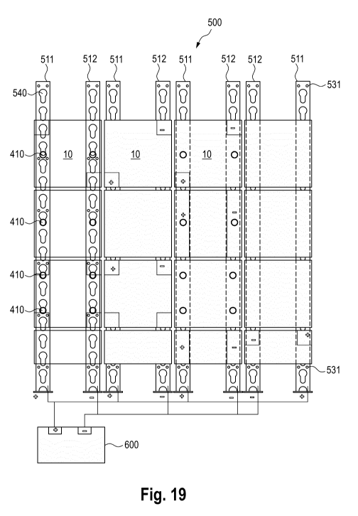
Fig. 19 shows a schematic illustration of a mounting rail assembly
with wall
members mounted thereon;
Date Recue/Date Received 2021-10-01
CA 03135819 2021-10-01
28
Fig. 20 shows a schematic illustration of a further mounting rail
assembly with
wall members mounted thereon;
Fig. 21 shows a schematic illustration of a further mounting rail
assembly with
wall members mounted thereon;
Fig. 22 shows a flowchart of a method;
Fig. 23 shows a first exemplary illustration of an arrangement of contact
needles
on a current collector;
Fig. 24 shows a second exemplary illustration of an arrangement of contact nee-
dles on a current collector;
Fig. 25 shows a third exemplary illustration of an arrangement of contact nee-
dles on a current collector;
Fig. 26 shows a fourth exemplary illustration of an arrangement of contact nee-
dles on a current collector;
Fig. 27 shows an illustration of arrangements of contact needles on a current-
carrying member in different positions and rotations
Fig. 28 shows a further illustration of different arrangements of
contact needles
on a current-carrying wall member in different positions and rotations
Fig. 29 shows an arrangement of three contact needles in combination with a
rectifier;
Fig. 30 shows an arrangement of four contact needles in combination with a rec-
tifier;
Date Recue/Date Received 2021-10-01
CA 03135819 2021-10-01
29
Figs. 31A to C show a top view as well as first and second side views of a
current
collector for an electrical device;
Fig. 32 shows a perspective view of an exemplary current collector;
Fig. 33 shows a perspective view of an exemplary current collector with a mag-
netic holder;
Fig. 34 shows a flowchart of a method
[0093] Fig. 1 shows an exemplary presentation stand 100 or a shop
window
construction with a system according to an embodiment of the present
disclosure. The
presentation stand 100 comprises a plurality of wall members 10. Each side may
be com-
posed of a plurality of individual wall members. The wall members 10 may be
mounted on
and powered by a mounting rail assembly comprising one or more current
carrying mount-
ing rails. Various objects 5 can be attached to the wall members 10. For this
purpose, var-
ious fasteners known from store fitting or trade fair construction can be
used. In a pre-
ferred embodiment, the objects can be magnetically attached to the wall
members 10. An
advantage of this solution is that the objects 5 can be positioned freely on
the wall mem-
bers 10. It shall also be understood that corresponding floor or ceiling
elements can be
provided, which are also referred to as wall members in the context of the
present disclo-
sure for the sake of simplicity. The objects may be electrical devices 5, such
as a light
source, lighting equipment, a screen, a motor, a loudspeaker, a mannequin or
the like. For
the power supply, current collectors are provided which are electrically
connected to the
electrical consumers 5 or can be configured as part of the objects or
electrical devices.
[0094] With the proposed wall member 10 and the associated current
collector
20, presentation, sales or exhibition stands 100, especially in modern
showrooms, can be
easily modified and, in particular, easily adapted to local conditions, thus
providing a high
degree of flexibility with regard to the design freedom of the presentation,
sales or exhibi-
tion stand 100. Such wall members 10 can also be used in store fitting.
Furthermore, the
system can advantageously also be used in museums or in the smart home sector.
Date Recue/Date Received 2021-10-01
CA 03135819 2021-10-01
[0095] Compared to conventional exhibition stands, there is no need
for com-
plex wiring of electrical devices, which not only simplifies assembly and
disassembly con-
siderably, but also allows the electrical consumers to be positioned almost
freely and vari-
ably. For the construction of the presentation, sales or exhibition stand 100,
several wall
members 10 are typically assembled. With the proposed current-carrying wall
members
with back side contacting, the assembly can be further simplified. In
particular, an electri-
cal supply of the wall members 10 can be achieved by providing a current-
carrying mount-
ing rail arrangement and the current-carrying wall member 10 in such a way
that, upon
hooking and/or clamping the wall member, an electrically conductive connection
is estab-
lished between the current-carrying mounting rail assembly and the current-
carrying wall
member.
[0096] A peculiarity of the proposed system can be that the current
collectors
10 or the electrical consumers 5 can not only be flexibly positioned on the
wall members 1
with regard to their horizontal and vertical position, but that rotation can
also be enabled.
For this purpose, the proposed system comprises at least one current-carrying
wall mem-
ber 10 and a current collector 20 for an electrical device 5. An embodiment of
a current-
carrying wall member 10 is shown in Figs. 2 and 3. Exemplary embodiments of
current
collectors are shown in Fig. 4 if.
[0097] Fig. 2 shows a schematic illustration of a first embodiment
of a wall
member 10 without cover. The wall member 10 comprises first electrical
conductor tracks
11 of a first polarity and second electrical conductor tracks 12 of a second
polarity. The
first and second electrical conductors 11, 12 are arranged alternately at
least in sections.
The first electrical conductors 11 can form a first comb-like structure. The
second electri-
cal conductors 12 can form a second, corresponding comb-like structure,
whereby the first
comb-like structure and the second comb-like structure are formed such that
the comb-
like structures engage in one another. An insulation gap is provided between
the first and
second electrical conductors 11, 12. The insulation gap ensures that no short
circuit oc-
curs. Preferably, the width of the insulation gap should be as small as
possible, for exam-
ple less than 2 mm, in particular less than 1.5 mm, in particular less than
1.0 mm, in par-
ticular less than 0.5 mm, in particular less than 0.2 mm. The width of the
isolation gap can
Date Recue/Date Received 2021-10-01
CA 03135819 2021-10-01
31
be smaller than 1/10, especially smaller than 1/20 of a conductor track width.
This can re-
duce the probability of one of the contact needles falling into the isolation
gap. However,
the insulation gap can be larger than a width of a tip of a contact needle of
a current col-
lector to avoid a short circuit between the conductive electrical tracks of
the first polarity
11 and the conductive electrical tracks of the second polarity 12. The
conductor tracks 11
of the first polarity are adapted to be connected to a first output of a
voltage source, e.g. a
positive pole 13. The conductor tracks 12 of the second polarity are adapted
to be con-
nected to a second output of a voltage source, for example a negative pole 14.
instead of
a DC voltage, the conductor tracks 11, 12 can also be supplied with an AC
voltage or a
combination of DC and AC voltage. An area of the current-carrying wall member
can be
covered by at least 70%, in particular by at least 85%, in particular by at
least 90% or 95%
with the first and second conductor tracks. The conductor tracks 11, 12 can be
part of a
carrier element 15 of the wall member 10 or alternatively be applied on the
carrier element
15. Advantageous embodiments of wall members with back side terminal contacts
are
shown in Fig. 6 if.
[0098] Fig. 3 shows a schematic illustration of a wall member 10,
which com-
prises an optional cover 18. For example, the cover 18 can cover the
electrical conductor
tracks 11, 12 applied to the carrier plate 15. Alternatively, the conductor
tracks 11, 12 can
be part of the cover. In this case, the conductor tracks may have the same or
similar ge-
ometry as the conductor tracks described above and shown in Fig. 2. To attach
the cover
18 to the wall member 10, a piping rail 17 (or a piping profile) can be
provided at the edge,
into which e.g. a piping strip on the cover side can be inserted. The piping
rail can be
made of silicone or aluminum, for example. It shall be understood that the
cover 18 may
cover a plurality of wall members 10. Thus, several wall members 10 can be
arranged
within the surrounding piping rails 17.
[0099] Fig. 4 shows a side view of a system comprising a wall
member 10 and
a current collector 20 attached to the wall member 10. Fig. 5 shows an
enlarged view of
the current collector 20 from Fig. 4 on the wall member 10. The wall member 10
com-
prises a carrier plate 15 and optionally a cover 18 covering it. The wall
member 10 also
Date Recue/Date Received 2021-10-01
CA 03135819 2021-10-01
32
comprises first electrical conductor tracks 11 of a first polarity and second
electrical con-
ductor tracks 12 of a second polarity, the first and second electrical
conductor tracks 11,
12 being arranged alternately at least in sections.
[00100] The wall member 10 comprises a carrier plate having a front side and a
back side. The first electrical conductor tracks 11 and the second electrical
conductor
tracks 12 are arranged on the front side of the carrier plate 15. The wall
member 10 com-
prises a first electrical terminal contact 13 and a second electrical terminal
contact 14. As
shown in Fig. 4, the first electrical terminal contact 13 is electrically
conductively coupled
to the first electrical conductor tracks 11. The second electrical terminal
contact 14 is elec-
trically conductively coupled to the second electrical conductor tracks 12.
The first electri-
cal terminal contact 13 and the second electrical terminal contact 14 are
arranged on the
back side of the carrier plate 15. For example, planar or areal terminal
contacts 13, 14 can
be provided. The terminal contacts 13, 14 can be brought into contact with
corresponding
connection elements or electrodes, for example on a wall or on a presentation
stand, as
shown for example in Figs. 11 to 13, in order to supply electrical power to
the wall mem-
ber. A front side of the wall member may refer to that side of the wall member
10 on which
the current collector 20 is attachable. A back side of the wall member may be
understood
as the side opposite to the front side.
[00101] In the example shown in Fig. 4, the first and second electrical
terminal
contacts 13, 14 on the back side are connected by electrical connections
through the car-
rier plate 15 to the respective corresponding electrical conductor track 11,
12 on the front
side.
[00102] Optionally, the first and/or second electrical terminal contact can
com-
prise a contact spring 420 for electrically contacting the current-carrying
mounting rail. Op-
tionally, the wall member 10 can comprise, on the back side of the carrier
plate 15, at
least one retaining element 410 which is adapted to hook the wall member into
the cur-
rent-carrying mounting rail assembly and/or to attach the wall member 10 to
the mounting
rail assembly in a clamping manner. This embodiment will be described in more
detail be-
low with reference to Fig. 17 if.
Date Recue/Date Received 2021-10-01
CA 03135819 2021-10-01
33
[00103] The current collector 20 comprises a plurality of at least two, in
particular
at least three contact needles 21a, 21b, 21c. The current collector 20 is
adapted to be
mounted on the wall member 10 such that at least one of the contact needles
21a con-
tacts one of the first electrical conductor tracks 11 and at least one other
of the contact
needles 21b contacts one of the second electrical conductor tracks 12. Here, a
first con-
tact needle 21a, a second contact needle 21b, and a third contact needle 21c
of the plu-
rality of contact needles can be arranged such that they are arranged on a
circle, as ex-
plained in more detail with reference to Fig. 17 if. below.
[00104] To attach or mount the current co11ector20 to the wall member 10, the
wall member 10 and the current collector 20 can be adapted such that the
current collec-
tor can be magnetically attached to the wall member. For example, the current
collector
20 may comprise one or more magnets 32 as shown in Fig. 4 and 5. The
electrical con-
ductor tracks 11, 12 and/or the carrier plate may comprise a magnetic material
so that the
current collector can adhere to it.
[00105] The contact needles 21a-c of the current collector can be connected to
a
rectifier 22. The rectifier can be part of the current collector or part of an
electrical device 5
that can be connected to the current collector. The rectifier 22 is adapted to
provide an
output voltage of defined polarity based on an input voltage applied to at
least two of the
contact needles 21a-c. Output pins 24a, 24b can be provided for this purpose,
to which an
electrical device 5 can be connected. The rectifier may comprise at least two,
in particular
at least three inputs 23a-G and two outputs 24a,b, each of the at least three
inputs 23a-G
being connected or connectable to a respective contact needle 21a-c. Exemplary
embodi-
ments of such rectifiers in the form of bridge rectifiers are shown in Fig. 29
and 30. Op-
tionally, the rectifier 22, the current collector 20 and the electrical device
5 can form a unit
6. Optionally, the current collector 20 and the rectifier 22 can be part of
the electrical de-
vice 5.
[00106] It shall be understood that the current collector or contact needles
can
optionally comprise a contact spring 26 for the contact needles, as shown in
Fig. 5, so as
to provide a defined contact pressure.
Date Recue/Date Received 2021-10-01
CA 03135819 2021-10-01
34
[00107] Figs. 6 to 8 show schematic illustrations of exemplary wall members.
Herein denote: A a front view, B a rear view, C a first side view and D a
second side view.
In an optional embodiment, an electrically conductive layer 70, for example an
electrically
conductive foil may be provided, as shown in view E, which may be applied to
the carrier
plate.
[00108] As shown in Fig. 6A, the wall member 10 comprises first electrical con-
ductor tracks 11 of a first polarity and second electrical conductor tracks 12
of a second
polarity on the front side of the carrier plate 15. The first and second
electrical conductor
tracks 11, 12 are alternately arranged at least in sections. A current
collector 20 placed on
the wall member 10 may be arranged to establish an electrical connection to
the first and
second electrical conductor tracks 11, 12.
[00109] In the embodiment example shown in Fig. 6, an extension 61 of the
first
electrical conductor tracks 11 around an edge 63 of the carrier plate may be
guided from
the front side to a back side of the carrier plate 15. Accordingly, an
extension 62 of the
second electrical conductor tracks 12 may be guided around a (second) edge 64
of the
carrier plate from the front side to a back side of the carrier plate 15. This
is exemplarily
shown in Fig. 6A to D.
[00110] Fig. 6C shows a side view of how the extension 61 is wraps around the
edge of the carrier plate from the front side to the back side. The rear view
is shown in
Fig. 6B. The extension 61 of the first electrical conductor tracks 11 is
electrically conduc-
tively connected to the first back side terminal contact 13. The extension 62
of the second
electrical conductor tracks 12 is electrically conductively connected to the
second back
side terminal contact 14. Optionally, the extensions 61, 62 may serve as back
side termi-
nal contacts. However, the terminal contacts 13, 14 may comprise further
elements. For
example, the first and/or second backside terminal contacts 13,14 may comprise
a mag-
net for magnetically attaching the wall member to a support structure, such as
an elec-
trode assembly or a wall. A magnet or other attachment means may be provided
as a sep-
arate element. Advantageously, current conducting magnets, such as
conductively coated
neodymium magnets may be used.
Date Recue/Date Received 2021-10-01
CA 03135819 2021-10-01
[00111] Fig. 6E shows an illustration of an electrically conductive layer 70
in an
exemplary embodiment as an electrically conductive film. The electrical
conductor tracks
11, 12 and the extensions 61, 62 may be implemented as a conductive foil. The
exten-
sions may thus be guided around the edges of the carrier plate in a simple
manner.
Hereby, parts of the electrically conductive layer 70 may serve as terminal
contacts 13,
14. It shall be understood that an insulating layer 65 may be provided between
the electri-
cal conductor tracks 11, 12 and the carrier plate 15. This may prevent the
conductive
paths 11, 12 from being short-circuited by the carrier plate 15. For example,
if the carrier
plate 15 is made of a conductive material such as steel.
[00112] Exemplary wall members are shown in Figs. 10 and 11, respectively, in
rows one, columns one and two with a front view and a rear view.
[00113] In embodiment, the extensions 61,62 or terminal contacts 13, 14 may
be arranged such that during manufacturing the extensions or terminal contacts
may be
arranged interleaved with each other. An advantage of this embodiment is that
material is
saved.
[00114] Fig. 7 shows a schematic illustration of another exemplary wall member
10. In order to avoid repetitions, in the following potential differences over
the previously
described embodiment will be highlighted.
[00115] As shown in Fig. 7A, the first electrical traces 11 and the second
electri-
cal conductor tracks 12 may form an engaging or interleaved comb structure.
The first
electrical conductor tracks 11 form a first comb and the second electrical
conductor tracks
12 form a second comb. In the exemplary embodiment shown in Fig. 6A, for both
combs,
the prongs or tines of the comb structure are arranged on the front side of
the carrier plate
15. In Fig. 6A, a web connecting the prongs is also arranged on the front side
of the car-
rier plate 15. in contrast thereto, according to Fig. 7, for at least one of
the two combs, a
web 66 of the comb structure connecting the tines may be arranged on the back
side of
the carrier plate '15. Thereby, a better utilization of the area of the front
side can be
achieved. Also in the edge regions of the wall member 10, the probability that
at least one
Date Recue/Date Received 2021-10-01
CA 03135819 2021-10-01
36
of the contact needles of the current collector 20 contacts one of the first
electrical con-
ductor tracks 11 and at least another one of the contact needles contacts one
of the sec-
ond electrical conductor tracks 12 can thus be increased. In the exemplary
embodiment
shown in Fig. 7E, folded edges are shown as a dashed line 73 along which the
foil can be
wrapped around the edges 63, 64 of the carrier plate 15.
[00116] In Figs. 6 and 7, generally the same or similar carrier plate 15 may
be
used. Different embodiments may be realized by covering the carrier plates 15
with a dif-
ferent film 70, as shown in Fig. 6E and Hg. 7E. It shall be understood that
such a film may
have a layered structure comprising multiple layers. At least one conductive
layer may be
provided to form the first electrical conductor tracks 11 and the second
electrical conduc-
tor tracks 12. Further, at least one insulating layer may be provided to
provide electrical
insulation with respect to the carrier plate 15. Further, one or more cover
layers may op-
tionally be provided. This may, for example, also be a cover as described
above.
[00117] As already described for Fig. 6, the first and second electrical
terminal
contacts 13,14 may be formed directly by extensions 61,62 of the electrical
conductor
tracks 11,12.
[00118] In the backside view of the wall member 10 shown in Fig. 7B, the first
and second electrical terminal contacts 13, 14 are arranged rotationally
symmetrically on
the back side of the carrier plate 15. This allows the wall members 10 to be
mounted with
more flexible orientation, as exemplarily shown in Fig. 10. In the context of
the present
disclosure, a rotationally symmetrical arrangement may refer to an arrangement
wherein,
when the carrier plate is rotated about its center point about an axis
orthogonal to the front
side of the carrier plate, at least a partial area of the second electrical
terminal contact
comes to rest at a position which corresponds to at least a partial area of
the former posi-
tion of the first electrical terminal contact 13. A partial overlap during
rotation may thus be
sufficient.
Date Recue/Date Received 2021-10-01
CA 03135819 2021-10-01
37
[00119] Optionally, the wall member 10 further comprises a third electrical
termi-
nal contact 13' and a fourth electrical terminal contact 14', wherein the
third electrical ter-
minal contact 13' is electrically conductively coupled to the first electrical
conductor tracks
11 and wherein the fourth electrical terminal contact 14 is electrically
conductively cou-
pled to the second electrical conductor tracks 12. The third electrical
terminal contact 13'
and the fourth electrical terminal contact 14' are arranged on the back side
of the carrier
plate. In the shown exemplary embodiment, the carrier plate 15 is square. The
four termi-
nal contacts are arranged rotationally symmetrically on the back side of the
carrier plate
15, in the present example in pairs at diagonally opposite corners on the back
side of the
carrier plate. This allows the plate to be mounted rotated by 90 on a wall or
on a support
structure, as shown in Fig. 10. Exemplary wall members are shown in Figs 10
and 11 in
row three columns one and two respectively, with a front view and a rear view.
[00120] By arranging the contact elements 13,14 in the edge areas on the left
and right side of the back surface of the carrier plate 15, a material usage
can be reduced.
In particular, a central area of the rear surface of the carrier plate 15 can
remain free.
[00121] Fig. 8 shows a further embodiment of a wall member 10. In this embodi-
ment, the first electrical terminal contact 13 is arranged in a first edge
region on the back
side of the carrier plate 15 and the second electrical terminal contact 14 is
arranged in a
second opposite edge region on the back side of the carrier plate 15. Hereby,
the connec-
tion contact may simultaneously provide the function of the web 66 of the comb
structures
connecting the respective conductive tracks 11 to each other. Optionally, the
conductor
tracks may be wrapped around to the back side of the carrier plate 15 and
connected to
each other by the extensions 61 of connection terminals formed as bars.
Exemplary wall
members are shown in Figs 10 and 11 in row two columns three and four
respectively,
with a front view and a rear view.
[00122] In the embodiment shown in Fig. 10, the system comprises a combina-
tion of wall members with front-side conductor tracks and wall members without
front-side
conductor tracks. Thus, simpler, less expensive elements can be used in areas
where no
power supply is required.
Date Recue/Date Received 2021-10-01
CA 03135819 2021-10-01
38
[00123] Fig. 9 therefore shows an exemplary embodiment of a wall member
without conductive tracks on the front side. However, the wall member 10 may
have an
insulating layer 65, in particular in one or more regions 68 in which
electrical contact is
usually made.
(001241 Fig. 9E shows an insulation layer in the form of a flat film.
Optionally,
however, smaller foil areas may also be provided, for example as indicated in
Fig. 9 E by
reference sign 68. A part of the carrier plate 15 can remain free. This can
save material.
[00125] Figs. 10 and 11 show a schematic representation of a front view and a
rear view, respectively, of a wall equipped with an arrangement of a plurality
of wall mem-
bers. For example, this may be the rear of a shop window or exhibition stand
as shown in
Fig, 1. Instead of large wall members, the system may comprise a plurality of
wall mem-
bers 10. An advantage arises in particular if the system has a combination of
wall mem-
bers with front-side conductor tracks and wall members without front-side
conductor
tracks. In this way, the manufacturing effort can be reduced and costs can be
saved.
[00126] Advantageously, the wall members can be attached to the wall via a de-
tachable connection, in particular magnetically. This allows the wall members
to be easily
exchanged and reorganized. For example, areas which were previously equipped
with a
wall member without front-side conductor tracks can now be provided with a
wail member
with front-side conductor tracks. Furthermore, the number of wall members with
or without
front-side conductor tracks can be increased or reduced. This allows an exact
adaptation
to the customer's requirements and the available budget. A subsequent upgrade
is thus
possible.
[00127] As shown in the rear view in Fig. 11, the system may comprise an elec-
trode arrangement for supplying power to the wall members via the first and
second rear
connection terminals 13, 14. The electrode arrangement comprises a first group
of elec-
trodes 81 and a second group of electrodes 82. For example, a positive pole
may be pro-
vided via the electrodes 81 and a negative pole may be provided via the
electrodes 82.
Date Recue/Date Received 2021-10-01
CA 03135819 2021-10-01
39
The first group of electrodes 81 is adapted and arranged to connect the first
electrical ter-
minal contacts 13 of the respective wall members with a first polarity. The
second group of
electrodes 82 is adapted and arranged to connect the second electrical
terminal contacts
14 of the respective wall members 15 to a second polarity. The proposed
arrangement al-
lows the wall members to be flexibly arranged and, in particular, to be
rotated in 180 or
90' steps.
[00128] An advantage of the proposed solution may in particular be that even
designers and decorators without in-depth knowledge of electrical engineering
can re-
place and reposition wall members. Even though turning wall members may lead
to a
change in the polarity of the first and second electrical conductor tracks.
However, this is
generally not critical. In the case of current collectors, it is also not
known in advance
which of the needles will be in contact with conductive paths of the first and
second polari-
ties. For example, a rectifier may thus be provided, as shown in Figs. 29 and
30.
[00129] In Fig. 11, the electrodes of the first group 81 and the electrodes of
the
second group 82 are arranged in a checkerboard pattern in different rows and
different
columns. The electrode arrangement may include receiving elements or mounting
ele-
ments 88, which may be located between the electrodes of the first group and
the second
group and are not current carrying. For example, a power supply may be
provided via the
checkerboard -like electrode arrangement of respective diagonally opposite
corners of the
wall members 10. For the further corners of the wall members 10, it is
sufficient if these
are merely mounted on one or more mounts or mounting elements 88 or even
directly
mounted on a wail or a mounting stand.
[00130] Optionally, the wall members 10 with the first and second conductor
tracks as well as the backside terminal contacts contacting the same can be
arranged in
such a way that the wall member 10 may be shortened to a predetermined length.
For this
purpose, the first electrical terminal contact 13 and the second electrical
terminal contact
14 may be arranged, at least in sections, on the same side or on the same edge
on the
back side of the carrier plate 15. Examples of wall members 10 which can be
shortened in
this way are shown in Figs. 7 and 8. As shown in Fig. 11 row 4 columns 3 and
4, a length
Date Recue/Date Received 2021-10-01
CA 03135819 2021-10-01
of the corresponding wall members 10 can thus be flexibly adapted to desired
application
scenarios.
[00131] Fig. 12 shows a schematic illustration of a second rear view of a
plurality
of wall members 10. The electrode arrangement herein comprises current-
carrying longi-
tudinal electrodes 85, 86. These may at the same time serve as mounting
elements for
the wall members 10. An advantage of this embodiment is easy assembly. It
shall be un-
derstood that the possible rotation states of the wall members may be limited
by the elec-
trode arrangement. For example, in case of the wall members shown in Fig. 7
and Fig. 8,
a short circuit must be avoided. This problem does not arise with the
checkerboard ar-
rangement of electrodes 81, 82 shown in Fig. 11. However, flexible rotation of
the wall
member shown in Fig. 6 or of the wall members shown in Fig. 10 line 1 columns
1 and 2 is
possible in conjunction with the electrode arrangement shown in Fig. 12.
[00132] Fig. 13 shows a further embodiment of a backside contact arrangement
for a plurality of wail members. Here, a plurality of electrodes may be
attached to the wall,
wherein the electrode arrangement comprises a first group of electrodes 91
connected to
a first polarity, for example a positive pole, and a second group of
electrodes connected to
a negative pole.
[00133] An exemplary connection of multiple electrodes is shown in Fig. 14. An
electrode 90 of the electrode arrangement may comprise a fastening means 96,
for exam-
ple in the form of a screw, which may be fastened in a wall 140, for example
by means of
a dowel. The electrode 90 may further comprise a retaining element, for
example a mag-
net 95, by means of which the wall member 10 may be attached to the electrode.
With this
type of attachment, a synergistic effect may result if a load is also
magnetically attached to
the wall member. Furthermore, the electrode 90 may comprise a connector 97 to
which a
supply line may be connected. In particular, the connection 97 can be designed
in such a
way that a continuation to or contacting of further electrodes is possible.
[00134] In order to improve mechanical stability, non-contacted electrodes or
el-
ements may be provided, as indicated by reference numeral 93 in Fig. 13.
Date Recue/Date Received 2021-10-01
CA 03135819 2021-10-01
41
[00135] Fig. 15 shows a further example of a rear view of a current-carrying
wall
member with a first back side terminal contact 13 and a second back side
terminal contact
14. An insulating layer 65 may be provided at least partially on the back
side. It may have
recesses for the first and second terminal contacts 13 ,14.
[00136] Fig. 16 illustrates a flow diagram of a method 300 for manufacturing a
wall member.
[00137] In a first step S301, a (ferromagnetic) carrier plate is provided, the
car-
rier plate having a front side and a back side.
[00138] In a subsequent step S302, first electrical conductor tracks of a
first po-
larity and second electrical conductor tracks of a second polarity are
applied, the first and
second electrical conductor tracks being alternately arranged at least in
sections; wherein
the first electrical conductor tracks and the second electrical conductor
tracks are applied
to the front side of the carrier plate.
[00139] In a step S303, a first electrical terminal contact and a second
electrical
terminal contact are applied to the back side of the carrier plate, wherein
the first electrical
terminal contact is electrically conductively coupled to the first electrical
conductor tracks,
and wherein the second electrical terminal contact is electrically
conductively coupled to
the second electrical conductor tracks.
[00140] For example, for steps S302 and S303, an electrically conductive film
as
shown in Figs. 6E to 8E may first be applied to the front surface of the
carrier plate, ac-
cording to step S302, and then folded around the edges of the carrier plate to
be applied
to the back surface, according to step S303.
[00141] The following describes embodiments with current carrying wall mem-
bers for attachment to a mounting rail assembly comprising one or more current
carrying
mounting rails.
Date Recue/Date Received 2021-10-01
CA 03135819 2021-10-01
42
[00142] Fig. 17 shows a variation of the schematic representations of an exem-
plary wall member already described in detail in Fig. 7. To avoid repetition,
differences
and additional features will be highlighted.
[00143] As shown in the rear view in Fig. 17 B and the side views in Fig. 17C
and D, the wall member 10 comprises at least one retaining element 410 on the
back side
of the carrier plate 15, which is adapted to hook the wall member into the
mounting rail as-
sembly and/or to fasten the wall member to the mounting rail assembly in a
clamping
manner. In the example shown in Fig. 17 C and D, the retaining element 410 is
configured
as a pin with a mushroom head. Such a mushroom head can, for example, engage
in re-
cesses 540 of a mounting rail 511, 512 of a mounting rail assembly 500
configured as a
keyhole rail, as shown in Figs. 19 and 20. Thus, the retaining elements 410
may be in-
serted into the wide portion of the recess 540 and then slid into the narrow
portion of the
recess 540. Thereby, a secure attachment can be established.
[00144] The current carrying mounting rail assembly and the current carrying
wall member 10 are advantageously configured such that when the wall member is
hooked and/or clamped, an electrically conductive connection is established
between the
current carrying mounting rail arrangement and the current carrying wall
member. The first
and/or second electrical terminal contact 13, 14 may, as current collectors in
order to tap
current from the mounting rails 511, 512, comprise an optional contact spring
420 for elec-
trically contacting the current-carrying mounting rail 511, 512. In the
example shown in
Fig. 17D, the mushroom head of the retaining element 410 may thus engage a
keyhole
rail and the contact spring 420 may tap a current from the keyhole rail. The
retaining ele-
ment 410 may be attached to the carrier plate 15, for example, by means of an
electrically
insulating adhesive connection.
[00145] The retaining (holding) elements 410 are advangeously arranged sepa-
rately from the first and second electrical terminal contacts 13, 14 on the
back side of the
carrier plate 15. In the present embodiment with contacts wrapped around to
the back
side, a mechanical suspension or fastenings at the contacts could lead to a
detachment or
delamination of the possibly glued-on connection contacts 13, 14.
Date Recue/Date Received 2021-10-01
CA 03135819 2021-10-01
43
[00146] Fig. 17F shows a variation of the retaining elements 410 as hooks
which
can engage in recesses of a mounting rail. Fig. 17G shows a further variation
of the re-
taining elements which are adapted to be clamped to a mounting rail, for
example a top
hat rail, as shown in Fig. 21. It shall be understood that other types of
retaining rails, such
as rails having a C-shaped or G-shaped profile, may also be used.
[00147] Fig. 18 shows a variation of the schematic illustrations of an
exemplary
wall member already described in detail in Fig. 6. The optional contact
springs are omit-
ted. The first and second electrical terminal contacts 13, 14 on the back side
of the carrier
plate 15 can establish a connection with the current-carrying mounting rails.
The number
of retaining elements 410 is also reduced to two. The first retaining element
410 is ar-
ranged in a first edge region on the back side of the carrier plate and the
second retaining
element 410 is arranged on a second opposite side in a second opposite edge
region on
the back side of the carrier plate. To prevent tilting, a first spacer 430 may
be arranged on
the side of the first retaining element 410 on the back side of the carrier
plate 15 and a
second spacer 430 may be arranged on the side of the second retaining element
410 on
the back side of the carrier plate 15. As can be seen from the side view in
Fig. 18 D, the
spacers 430 are adapted to provide a defined distance between the back side of
the car-
rier plate 15 and a respective first and second mounting rail, the defined
distance corre-
sponding to that distance which is established by the first and/or second
retaining element
between the back side of the carrier plate and the respective first and second
mounting
rail. A carrier plate can thus be attached to the mounting rails 511, 512 of
the mounting rail
arrangement by means of two retaining elements 410, as shown for example in
Figs. 19
and 20 in the first and third rows in the first and third columns.
[00148] Fig. 19 shows a schematic representation of a mounting rail assembly
500 with a plurality of wall members 10 attached thereto. The mounting rail
assembly 500
comprises a plurality of current carrying mounting rails 511, 512. They are
connected to a
current or voltage source 600 such that the mounting rails supply current of a
first and a
second polarity to wall members attached thereto, for example positive pole
and negative
pole of a DC voltage source or the phases of an AC voltage source.
Date Recue/Date Received 2021-10-01
CA 03135819 2021-10-01
44
[00149] The mounting rails 511, 512 comprise a plurality of recesses 540. The
recesses 410 are arranged in a regularly spaced manner. The spacing of the
recesses
540, the length or height of the wall members 10 and the arrangement of the
retaining ele-
ments 410 are coordinated in such a way that a length of the wall member 10
corresponds
to an integer multiple of a spacing between two recesses 540 of the mounting
rails 511,
512. When a plurality of retaining elements 410 are provided per wall member
10, a spac-
ing of the retaining elements 410 (in a direction of a longitudinal extension
of the mounting
rail 511, 512) may also correspond to an integer multiple of a spacing between
two re-
cesses 540 of the mounting rail 511, 512.
[00150] In order to clarify the arrangement of the wall members 10 and
mounting
rails 511, 512 as well as the retaining elements 410, the wall members 10 are
shown
transparent in the left column of the arrangement in Figs. 19 and 20 as well
as in the up-
per row in Fig. 21. In the right-hand two columns in Figs. 19 and 20 and in
the bottom row
in Fig. 21, the mounting rails located behind the wail members 10 are
indicated by dashed
lines. For example, the mounting rails 511, 512 may have screw holes for
screwing the
mounting rails to the wall. It will be understood that the mounting rail
assembly may also
be attached to the wall in other ways.
[00151] Fig. 20 shows a schematic representation of a further mounting rail as-
sembly 500 with a plurality of wall members 10 attached thereto. In this
embodiment, a
portion of the current-carrying mounting rails 511, 512, 513, 514 is
configured as double
rails 513 and 514 for simultaneously receiving wall members arranged next to
each other.
This can further reduce the assembly effort and facilitate the alignment of
adjacent wall
members.
[00152] Fig. 21 is a schematic illustration of another mounting rail assembly
500
with wall members attached thereto. In this example, the mounting rails 511,
512 are
mounted horizontally. For example, the mounting rails 511, 512 may be top hat
rails into
which the wall members may be suspended or clipped by means of corresponding
retain-
ing elements 410, for example with as shown in Fig. 17G.
Date Recue/Date Received 2021-10-01
CA 03135819 2021-10-01
[00153] Fig. 22 illustrates a flowchart of a method for a presentation, sales
or ex-
hibition stand 100 and/or shop fitting which may be carried out in connection
with a sys-
tem according to the present disclosure. In a first step S701, a current
carrying mounting
rail assembly comprising a plurality of mounting rails is provided. The
mounting rails may
be connected to a power source and are arranged to provide power to the wall
members.
The mounting rails are arranged such that a plurality of current carrying wall
members ac-
cording to the present disclosure can be mounted thereto, preferably without
gaps.
[00154] In a step S702, the current-carrying wall members can be mounted on
the current-carrying mounting rail assembly. With a sufficiently large
mounting rail assem-
bly, further wall members can also be added subsequently. For example,
initially provided
wall members without conductive tracks can also be subsequently replaced by
wall mem-
bers with conductive tracks. In this way, a presentation wall can also be
extended subse-
quently.
[00155] In a step S703, a cover covering a plurality of the wall members may
be
applied.
[00156] In a step S704, one or more electrical device or current collectors
for
electrical devices may then be attached to one or more wall members,
preferably magneti-
cally.
[00157] Embodiments of the current collector and, in particular, various
arrange-
ments of the contact needles are described below.
[00158] Figs. 23 to 26 show exemplary illustrations of arrangements of contact
needles 21a-f on a current collector 20. The current collectors 20 comprise a
plurality of at
least three contact needles 21a-21f respectively, where a first contact needle
21a, a sec-
ond contact needle 21b, and a third contact needle 21c of the plurality of
contact needles
21a-21f are arranged such that they lie on a circle 41. The circle 41 is shown
in dotted
auxiliary lines, as this is only serves to describe the type of arrangement.
Date Recue/Date Received 2021-10-01
CA 03135819 2021-10-01
46
[00159] In the example shown in Fig. 23, the current collector 20 comprises
three contact needles 21a-c, wherein the first, the second and the third
contact needle
21a-21c of the current collector 20 are arranged such that they form a
triangle 42, in par-
ticular an acute-angled triangle, in particular an isosceles triangle, and in
particular an
equilateral triangle.
[00160] Fig. 27 shows an illustration of the current collector shown in Fig.
23 or
respectively its contact needle arrangement in different positions and
rotations A to F. In
the background, the first electrical conductor tracks 11 and second electrical
conductor
tracks 12 of the wall member 10 are shown. The current collector 20 (more
precisely its
contact needle arrangement) is adapted to be attached to the wall member such
that at
least one of the contact needles 21a contacts one of the first electrical
conductors 11 and
at least one other of the contact needles 21b, 21e contacts one of the second
electrical
conductors 12. As can be seen from Fig. 27, even in a plurality of different
rotation states,
at least one of the contact needles can always be in contact with one of the
first electrical
conductor tracks 11, here the positive pole, and at least one of the contact
needles can be
in contact with one of the second electrical conductor tracks 12, here the
negative pole.
This applies even if, as shown in position C, one of the contact needles 21c
lies in an in-
sulation gap 19 between the tracks 11, 12.
[00161] Hereby, a diameter of the circle 41 (see Fig. 23), on which the first
con-
tact needle, the second contact needle and the third contact needle are
arranged, can be
smaller than or equal to the sum of a width 51 of one of the first conductor
tracks 11 and a
width 52 of one of the second conductor tracks 12 and optionally a width 53 of
the insula-
tion gap 19 between them. As shown in Fig. 27 at position E, two contact
needles 21b,
21c can also lie on different conductor tracks 12 of the same polarity,
whereby a third of
the contact needles 21a lies on a conductor track 11 of the other polarity.
Optionally, the
contact needles 21a-c can be arranged such that a distance between the first
contact nee-
dle 21a and a straight line through the second contact needle 21b and the
third contact
needle 21c is greater than a width 51, 52 of one of the electrical tracks 11,
12.
[00162] The following table shows exemplary combinations of conductive track
widths and circle diameters 41, assuming an insulation gap with a width of 1
mm and a
Date Recue/Date Received 2021-10-01
CA 03135819 2021-10-01
47
contact area of 0.5 mm. The first and second conductive tracks 11, 12 can have
the same
track width.
Electrical conductor Circle diameter d I
track width in mm in mm
9 16-17
17-19
11 18-21
14 22-27
24-29
19 29-37
30-39
[00163] Fig. 22 shows another illustration of different arrangements of
contact
needles on a current-carrying wall member in different positions and
rotations. However,
in a particularly unfavorable case, as shown in Fig. 22 position E, for
example, the second
contact needle 21b and the third contact needle 21c can fall into the
insulation gap 19 be-
tween the tracks 11, 12. In this special case, a power supply would not be
possible with-
out any further action. A first possible solution is to combine a first and a
second current
collector with different rotational orientations of the contact needles 21a-
21c, for example
with the orientations shown in Fig. 22 position A and position B. However,
this would re-
quire a not negligible amount of material.
[00164] Fig. 28 positions G to J show further exemplary remedies. As shown in
Fig. 25 and 26 and Fig. 28 position G, the current collector 10 can optionally
be provided
with a fourth contact needle 21d. The fourth or further contact needle 21d can
be arranged
within the circle 41, on which the first, second and third contact needle 21a-
c are located.
It shall be understood that such a further contact needle inside the circle
can also be pro-
vided in combination with further contact needles, as for example shown in
Fig. 24. in Fig.
24 such an optional further or second fourth contact needle is denoted 21g.
Thereby the
flexibility regarding free positioning and rotation of the current collector
relative to the wall
member can be further improved. In the examples shown in Fig. 26 and Fig. 28
G, the
Date Recue/Date Received 2021-10-01
CA 03135819 2021-10-01
48
fourth contact needle can be arranged in a center of circle 41 and/or in a
center of gravity
of triangle 42 (these points coincide for an equilateral triangle).
(00165] Optionally, the fourth contact needle 21d can be arranged spaced apart
decentered from a center of the circle 41, as shown in Fig. 25. This has the
advantage of
reducing the probability that, for example, the contact needles 21a and 21d
will lie in a
straight line 43, which is parallel to a horizontal or vertical axis of the
current collector 20.
The inventors recognized that the current collectors 20 are often aligned
horizontally or
vertically. Against this background, it can be advantageous to arrange the
positioning of
the contact needles turned with respect to a horizontal or vertical axis of
the current col-
lector 20, as shown in Fig. 26 and Fig. 28 position H. This can also provide
the advantage
of reducing the probability that, for example, contact needles 21a and 21d are
located on
a straight line 43 parallel to a horizontal or vertical axis of the current
collector 20. The use
of a fourth contact needle 21d is optional. in particular, exactly three
contact needles can
be provided in this case, so that the costs and the manufacturing effort can
be further re-
duced.
[00166] In a further exemplary embodiment the current collector 20 may also
comprise a fourth contact needle 21d, a fifth contact needle 21e and a sixth
contact nee-
dle 21f. The six contact needles 21a-f can be arranged as a hexagon,
especially as an
equilateral hexagon or star. As shown in the examples in Fig. 28 position I
and J, in this
case, even if two contact needles 21a and 21d, as shown in Fig. 28 position I,
or 21b and
21d, as shown in Fig. 28 position J, fall into the insulation gap 19, an
electrical connection
can still be established with one of the first electrical conductor tracks 11
and one of the
second electrical conductor tracks 12. Another advantage of this embodiment
can be that
when the current collector 20 is attached to the wall member 10, at least two
contact nee-
dles 210, 21f contact one or more of the first electrical conductor tracks 11
and at least
two of the contact needles 21b, 21c contact one or more of the second
electrical conduc-
tor tracks 12. This may allow higher current flows and thus higher power of an
electrical
device 5 connected to the current collector 20.
[00167] Fig. 29 shows an illustration of a current collector 20 with an
arrange-
ment of three contact needles 21a-21c in connection with a rectifier 22. Fig.
30 shows a
Date Recue/Date Received 2021-10-01
CA 03135819 2021-10-01
49
corresponding representation of a current collector 20 with an arrangement of
four contact
needles 21a-21d in connection with a rectifier 22. In the shown examples, a
diode bridge
rectifier is shown, but other types of rectifiers can be used. An advantage of
this solution is
a simple, low-cost design, which is also easily scalable for a larger number
of contact nee-
dles 21a-f. An output voltage of defined polarity is provided at outputs 24a,
24b, which can
be fed to an electrical load 5.
[00168] Fig. 31 A to C show a top view (C), as well as a first and a second
side
view (A. B) of a specific exemplary embodiment of a current collector 20 for
an electrical
device. Fig. 32 shows a perspective view of this current collector 20. Such a
current col-
lector can also be called a needle connector. Here the contact needles 21a-21d
can be
arranged on a lower side or first side of the housing and the current
interfaces 24a, 24b
can be arranged on an upper side or second (opposite) side of the housing. For
example,
the rectifier circuit 20 shown in Fig. 30 may be integrated into the current
collector 20.
Hence a compact component can be provided that can be handles easily.
[00169] In the shown example, the current collector comprises four contact nee-
dles, which may for example be arranged similar to the illustration shown in
Fig. 9. How-
ever, other arrangements or numbers of contact needles may be provided. In
particular,
the current collector 20 may be adapted such that, with horizontal or vertical
alignment of
the current collector, a straight line through the first and second contact
needles 21a, 21b
intersects a horizontal or vertical axis of the current collector at an acute
angle, in particu-
lar at an angle not exceeding 30 , in particular at an angle not exceeding 15
, in particular
at an angle not exceeding 5%.
[00170] Fig. 33 shows a perspective view of a current collector 20 with a
magnet
holder 30. The magnet holder 30 may comprise one or more magnets 32 adapted to
at-
tach the magnet holder 30 and thus the current collector 20 to a wall member
10 as
shown in Fig. 1. The magnet holder can have a receptacle 33 for the current
collector 20,
here in the form of a groove 33 provided on the magnet holder, which interacts
with a cor-
responding tongue 27 of the current collector 20.
Date Recue/Date Received 2021-10-01
CA 03135819 2021-10-01
[00171] Optionally, the current collector 20 (especially in combination with
the
holder 30) can be adapted such that the contact needles 21a-d can be moved
between a
contact position, in which the contact needles can contact the electrical
conductor tracks
of the wall member, and a non-contact position, in which the contact needles
are at a dis-
tance from the conductor tracks, when the current collector is placed on the
current-carry-
ing wall member. For this purpose, the current collector 20 may comprise a
spring ele-
ment 28, for example as shown in Fig. 31B and Fig. 32. The magnetic holder 30
may op-
tionally further comprise a slot 33 for an electrical device. In this case,
the electrical device
can be adapted to contact the output pins or output contacts 24a, 24b for
power supply in
an inserted position. Optionally, the current collector 20 in combination with
the holder 30
can be adapted to be moved from the non-contact position to the contact
position by in-
serting an electrical device into the plug-in unit or groove 33.
[00172] Fig. 34 shows a flow chart of a method 200, in particular for a
presenta-
tion, sales or exhibition stand (100) and/or for store fitting. In a first
step S201, a current-
carrying wall member as described in the present disclosure is provided. In a
second step
S202, a current collector as described in the context of the present
disclosure is provided.
In a third step S203, the current collector is attached to the current-
carrying wall member
in such a way that a first of the contact needles contacts one of the first
electrical conduc-
tor tracks and at least one other of the contact needles contacts one of the
second electri-
cal conductor tracks.
[00173] In an optional fourth step S204, a check of the position and rotation
of
the current collector (or of an electrical device comprising the current
collector or con-
nected to the current collector) can be performed. In an optional fifth step
S205 a correc-
tion of the position and/or rotation of the current collector can be made.
Steps S204 and
S205 can optionally be repeated iteratively until a desired position and
rotational align-
ment is reached. This can further improve the flexibility in the placement or
design of such
a presentation system. In particular, it is not necessary to define a position
and angular
alignment of the electrical consumers in advance, as they can be flexibly
adjusted.
[00174] It shall be understood that the embodiments described herein as exam-
ples can also be used in modified form, for example with a different number of
contact
Date Recue/Date Received 2021-10-01
CA 03135819 2021-10-01
51
needles, different dimensions, different distances between contact needles and
surfaces
and/or modifications of the geometric arrangement, within the scope of the
attached
claims respectively.
[001751 It shall be understood that the shown strictly vertical or horizontal
ar-
rangement of the electrical conductor tracks, as shown in Fig. 2, is to be
understood as an
example, so that they can also be provided thinner, thicker, diagonally or in
some other
way such as e.g. circular or meandering on the carrier element 15. For the
operation of
the electrical device 5 the current collector can interact with the electrical
conductor tracks
arranged on the carrier element in such a way that at least a first contact
needle can come
into electrical contact with one of the first conductor tracks and a second
contact needle
with one of the second conductor tracks. For the power supply, in particular
low-voltage
systems can be used, which work with 12/24 V and can therefore be used without
danger.
However, by using special insulators which are applied as varnish, foil and/or
other mate-
rials, it is also conceivable to use higher-voltage systems, i.e. systems
operating at higher
voltage, if necessary. Thanks to the e.g. needle-like design of the contacting
needles, they
can be moved frequently without damaging the cover. in general, the conductors
11, 12
usually carry low voltage, for example 12 or 24 V, so that the risk of injury
when handling
the proposed wall member 10 or the current collector 20 or an electrical
device 5 con-
nected to it can be almost completely excluded. The application of the
conductor tracks
11, 12 on the carrier plate 15 can be done for example by spraying, gluing or
welding. ln
particular, conductive lacquers can also be used for the conductor paths 11,
12 which are
sprayed/printed (e.g. by screen printing) onto the carrier plate 15.
[00176] It is also possible that the wall members 10 may not only be made
flat,
but can also be curved or arched. Modern magnets 6 enable magnetic forces of
consider-
ably more than 80 kg, so that even large electrical devices 5 or electrical
devices 5 ar-
ranged in special presentation elements, such as shelves 11 (see Fig. 1), can
be easily
mounted to the respective wall members 10.
[00177] The wall member 10 can also be designed flexibly, in particular it can
be
rolled up or down, so that it can for example be used as wallpaper or floor
covering. The
wall member 10 can be constructed as a sandwich material, which comprises the
current-
Date Recue/Date Received 2021-10-01
CA 03135819 2021-10-01
52
carrying conductors 11, 12 and can be used or mounted as wallpaper/carpet
(rolled mate-
rial) or panel material.
(00178] The sandwich construction can be done as follows: The cover 18 (sur-
face material) is configured as a thin, penetrable, flexible material, behind
this the conduc-
tor tracks 11, 12 are arranged on an insulating material, behind this there is
the carrier
material 15 made of plastic and/or of magnetic or magnetizable material, such
as steel.
[00179] The current collector 20 and/or the electrical consumer 5 can also be
in-
telligent or programmable. Data can be transmitted by modulating a signal on
one or both
of the electrical conductor tracks 11, 12 by means of so-called power line
communication
(PLC) or by wireless communication or optically. For example, different
current collectors
20 and/or electrical devices 5 can be selectively controlled. For example,
switching/dim-
ming/controlling of individual devices 5 is possible. Furthermore, a bus
system can also be
provided in which the electrical conductors 11, 12, the current collectors 20
and/or the
electrical devices 5 represent a part of the bus system and with which
individual devices 5
can be individually addressed/controlled.
(00180] Optionally, a wall member can also be adapted to be applied under a
wall covering, such as fiberglass wallpaper, and used for example in the field
of smart
home or in a museum. The current collectors can be used to supply electrical
devices,
such as lighting equipment for pictures or other exhibits or monitors
explaining the exhib-
its, with electrical energy.
(00181] Likewise, the proposed system can be used in an office or a private
home, where it can then be placed for example under a surface of textile, foil
or wood ve-
neer or other wall surface materials. By means of the current collectors it is
possible to
flexibly supply electrical devices at different positions and especially at
different angles of
rotation with electrical energy, without having to provide a multitude of
possibly ugly power
outlets. In particular when using a low-voltage system, the safety for
children or other per-
sons can be improved while at the same time providing increased flexibility.
Date Recue/Date Received 2021-10-01