Note: Descriptions are shown in the official language in which they were submitted.
CA 03136261 2021-10-06
WO 2020/212702 PCT/GB2020/050962
1
AXIAL FLOW TURBINE APPARATUS
Field of the Invention
This invention relates to a turbine apparatus for producing power from fluid
flow, for
example water flow. Particularly, the invention relates to an axial flow
turbine apparatus
comprising a rotor mechanism and a rotor support system, which is operable to
support
and control the position and alignment of the rotor mechanism relative to the
direction of
flowing water in a waterway, for example a river, estuary, channel, pipe, sea,
ocean etc.
Background to the Invention
Fluid-driven turbines have been known for many years. Despite this, there
remains a
need for turbines, particularly, water turbines, which can be installed in a
simple manner
and at low cost, for example to provide electrical power to small communities.
In most, water-based applications there is a reliance on relatively massive
civil and
structural engineering works. It will be appreciated that such an application,
often
requires the use of specialist plant, and produces a high capital cost per
unit of output.
There is a need for a novel approach, which uses significantly less material
mass and
simpler plant. Specifically, where it is desired to produce power from
naturally occurring
sources, for example in river flow, tidal streams or marine currents, it is
desirable for an
apparatus to be robust, simply transportable and simply positioned. In such an
application it would be desirable for a turbine to be deployable and
maintainable from
relatively small vessels.
Summary of the Invention
An axial flow turbine apparatus for deployment in a waterway, the turbine
apparatus
CA 03136261 2021-10-06
WO 2020/212702
PCT/GB2020/050962
2
comprising a rotor support system, a rotor mechanism and a power take-off
device,
wherein the rotor support system is operable to support and control position
and
alignment of the rotor mechanism relative to a direction of flow of flowing
water in the
waterway, wherein deployment of the turbine apparatus in flowing water
generates
power, wherein the rotor support system includes;
an elongated shaft, which includes:
a buoyancy adjusting component;
a flexible coupling at a first end; and
the rotor mechanism being attachable to a second free end of the
elongated shaft;
wherein the flexible coupling:
facilitates connection of the first end of the elongated shaft to a support
structure
located in the waterway in which the turbine apparatus is deployed, and
facilitates a
substantially freely yawing connection of the axial flow turbine apparatus to
the support
structure located in the waterway in which the turbine apparatus is deployed;
controls pitching and yawing motion of the elongated shaft and the rotor
mechanism relative to the rotor support system and support structure
respectively; and
in use, responds to changes in flow of the flowing water, to maintain the
turbine
apparatus with a compliant attitude, thereby maintaining alignment of the axis
of the
elongated shaft and the rotor mechanism with the direction of flow; and
wherein the buoyancy adjusting component is operable to maintain the deployed
turbine apparatus with substantially neutral buoyancy relative to the waterway
in which
the turbine apparatus is deployed.
Compliant attitude means the elongated shaft is substantially free (compliant)
to pivot in
a manner which allows axial alignment of the shaft relative to the direction
of flow
CA 03136261 2021-10-06
WO 2020/212702 PCT/GB2020/050962
3
(attitude). This ensures the axial flow turbine apparatus i.e. the assembly of
the rotor
mechanism and the rotor support system is aligned such that the orientation of
the rotor
mechanism is optimised for operation. If off-axis or imbalanced forces are
encountered
by the rotor mechanism such as due to turbulence, wave induced currents, or
collision,
then this compliant arrangement allows a momentary responsive change in
attitude of
the turbine apparatus to take place, shedding peak forces and so helping to
protect the
structure from damage.
It will be appreciated that reference to an axial flow turbine apparatus
relates to an
arrangement/assembly of components that convert the kinetic energy of moving
water,
wave motion or currents into electrical energy, useful work or other forms of
energy,
such as hydraulic power, mechanical power, heating, cooling, carbon
sequestration,
water desalination, ocean cleansing etc. The system utilises a power take-off
(PTO)
device, which, for example, is connected to the elongated shaft, the flexible
coupling or
as a hub of the rotor mechanism.
Neutral buoyancy is the condition in which the average density of an item is
equal to the
density of the fluid in which it is immersed. For this application the neutral
buoyancy
condition is hence defined such that when the rotor support system is attached
to its
support structure there is approximately a zero-moment acting about the
flexible
coupling due to the combined forces of weight, and buoyancy acting on the
freely
articulating rotor support system, particularly, the attached rotor mechanism
will not rise
or fall when immersed in the water at turbine operating depth.
It will be appreciated that a rotor mechanism may be heavy and therefore may
be liable
to sink (negative buoyancy), but the rotor support system is configured to
provide
neutral buoyancy to a turbine apparatus including a rotor mechanism, wherein
the
position of the rotor mechanism in a body of water is stable and does not rise
or fall, and
CA 03136261 2021-10-06
WO 2020/212702 PCT/GB2020/050962
4
the position of the rotor mechanism in the body of water is controlled by
adjusting
buoyancy, for example via a buoyancy adjusting component, which may be
provided as
part of the elongated shaft or to function relative to the elongated shaft.
The flexible coupling may comprise a pivotal pitch connector and a pivotal yaw
connector, wherein the pivotal pitch connector permits pitching motion of the
assembly
of the elongated shaft and the rotor mechanism relative to the rotor support
system and
the waterway in which the turbine apparatus is deployed. The yaw control
connector
may facilitate connection of the axial flow turbine apparatus to a support
structure in a
waterway and controls the degree of yawing motion of the axial flow turbine
apparatus
when deployed.
The turbine apparatus may further comprise extremity bump-stops, which
facilitate the
extent of pitching motion. Alternatively, the flexible coupling may comprise a
section of
flexible material connected to the first end of the elongated shaft, wherein
the flexible
material is of given stiffness or spring constant, and is operable to maintain
the
assembly of the elongated shaft and the rotor mechanism in a compliant
attitude and to
transmit axial torque.
The pivotal pitch connector may comprise a universal joint connecting the
elongated
shaft to a pivotal yaw connector. The universal joint may be a cardan joint,
for example
a single cardan type joint or a double cardan type joint.
Alternatively, the pivotal pitch connector may comprise a connector
facilitating single
degree of freedom movement of the assembly of the elongated shaft and the
rotor
mechanism. Examples of a connector facilitating single degree of freedom
movement
may comprise a chain link joint, a hook joint, a clevis joint etc.
The pivotal pitch connector permits pitching movement of the assembly of the
elongated
CA 03136261 2021-10-06
WO 2020/212702 PCT/GB2020/050962
shaft and rotor mechanism relative to a plane of flow when deployed in flowing
water
and whilst the flexible coupling facilitates connection of the first end of
the elongated
shaft to a support structure.
The flexible coupling may further comprise a resilient member operable in a
biasing
5 manner to maintain the assembly of the elongated shaft and the rotor
mechanism in a
compliant attitude relative to the support structure, toward a central or
straight position,
by permitting responsive movement of the assembly of the elongated shaft and
the rotor
mechanism and to limit the extent of pitching motion of the assembly of the
elongated
shaft and the rotor mechanism. The resilient member may be a spring associated
with
the pivotal pitch connector. The resilient member may be a helical spring
which is
mounted around the pivotal pitch connector such that the range of movement of
the
assembly of the elongated shaft and the rotor mechanism is substantially
unhindered in
water flow, but in the event of a change of flow direction or in still water
the spring is
operable to bias the assembly of the elongated shaft and the rotor mechanism
to a
predetermined neutral position relative to an axis of the pivotal yaw
connector.
Another example of a suitable resilient member may, for example, be formed by
an
arrangement of two hydraulic rams configured to position the pivotal pitch
connector, or
to act as dampers to absorb energy from dynamic pitching or thrust loads or
displacements exerted on the pivotal pitch connector during operation.
Where the flexible coupling is a universal-type joint, the resilient member
maintains
alignment of the pivotal yaw connector with the elongated shaft as the
elongated shaft
naturally aligns with direction of flow. Maintaining alignment, thus ensuring,
that the
flexible coupling yaws relative to the support structure, where the pivotal
yaw connector
allows the elongated shaft to yaw around the support structure in changing
flow, for
example changing tide. As such, any possibility of jack-knife of the flexible
coupling is
CA 03136261 2021-10-06
WO 2020/212702 PCT/GB2020/050962
6
avoided.
The flexible coupling facilitates free movement of the rotor mechanism to
align with the
flow path of the body of water in which the turbine apparatus is immersed. It
will be
appreciated this means that the turbine apparatus is configured such that the
rotor
mechanism can freely follow the direction of flow, for example tidal flow,
without
obstruction, due to the system being substantially neutral buoyant and due to
the
flexible coupling providing little or no obstruction to movement to direct the
rotor
mechanism in the direction of flow.
The first end of the elongated shaft may be located at a predetermined height
from the
bed of a body of water/waterway, for example sea, ocean, river, estuary,
harbour,
channel, pipe etc. in which the system is deployed. The system may be
pivotally
connected to a suitable support structure or system and may be arranged such
that the
rotor mechanism can freely orientate through 360 degrees in one plane, such
that the
rotor mechanism freely follows and aligns axially with the direction of flow
of water in the
body of water/waterway in which the system is deployed.
In use, a turbine apparatus comprising a rotor support system which includes
an
assembly of a flexible coupling, an elongated shaft, a rotor mechanism and a
power
take-off is such that the flexible coupling and the elongated shaft transmit
torque due to
rotation of the rotor mechanism and the power take-off facilitates the
conversion of the
motive/kinetic energy to electrical energy or other forms of energy, e.g.
hydraulic,
mechanical etc. In an example, the flexible coupling and the elongated shaft
may be
arranged to rotate in response to rotation of the rotor mechanism.
The pivotal yaw connector may comprise a mounting spike receivable in a hollow
support structure. Alternatively, the pivotal yaw connector may comprise a
hollow
member or channel into which can be received a tether such as chain, rope or
cable
CA 03136261 2021-10-06
WO 2020/212702 PCT/GB2020/050962
7
providing a support structure.
The pivotal yawing connector may be provided by a torque bar axially aligned
to and
mounted to a support structure comprising a tensioned tether member, wherein
the
torque bar is connected to the tether member and facilitates yawing motion and
controls
the extent of yawing motion of the turbine apparatus relative to the tether
member. The
tether member may comprise a rope, cable, chain etc.
The torque bar may comprise a T-shape arrangement, wherein the pivotal yaw
connector is formed by the head of the T and the pivotal pitch connector is
provided by
the body of the T. The T-shape ensures the axis of yaw and the axis of
pitching are
offset from each other by a predetermined distance to enhance stability and
functional
range of the turbine apparatus when deployed.
The axial flow turbine apparatus may further comprise a buoyancy adjusting
component, wherein the buoyancy adjusting component is movable relative to the
elongated shaft to adjust buoyancy distribution of the assembly of the
elongated shaft
and the rotor mechanism such that the position of the rotor mechanism relative
to the
body of water is neutrally buoyant or buoyantly stable.
The buoyancy adjusting component may comprise a mass connected to and movable
relative to the elongated shaft. The buoyancy adjusting component may comprise
a
mass connected to an external surface of the elongated shaft, the internal
surface of the
elongated shaft or both the internal and external surface of the elongated
shaft, wherein
the mass is movable along the elongated shaft to affect buoyancy distribution
of the
assembly of the elongated shaft and the rotor mechanism.
The orientation of the rotor mechanism and the elongated shaft may be adjusted
by
moving the position of the buoyancy adjusting component along the length of
the
CA 03136261 2021-10-06
WO 2020/212702 PCT/GB2020/050962
8
elongated shaft.
A buoyancy adjusting component comprising an external mass may be provided by
a
sleeve comprising a hollow tubular member, wherein the elongated shaft is
receivable
within the hollow of the hollow tubular member and wherein the sleeve can
slide along
the external surface of the elongated shaft.
The buoyancy adjusting component may include an inner tube within an outer
tube,
wherein the elongated shaft is received inside the inner tube and an annular
space is
defined between the inner tube and the outer tube.
The annular space may be filled with buoyant material. The buoyant material
may be
foam. Alternatively, or in addition, the buoyant material may be gas, for
example air,
nitrogen etc. Alternatively, the annular space may be substantially occupied
by a
plurality of elements, for example donuts, cylinders etc., which are made of
buoyant
material, wherein the donuts, cylinders, etc. are distributed along the length
of the
annular space,
Voids defined inside the elongated shaft may be filled with buoyant material,
for
example foam or gas. The function of the buoyancy adjusting component is to
assist
the assembly comprising the elongated shaft and the rotor mechanism to attain
neutral
buoyancy, whilst the system is deployed for operation to convert energy of the
moving
water to useful energy/work.
It will be appreciated, being able to adjust buoyancy of the system is also
beneficial for
maintenance, repair and moving location of the axial flow turbine apparatus,
wherein the
position of the buoyancy adjusting component can be changed relative to the
elongated
shaft to allow the rotor mechanism of a deployed system to be positively
buoyant i.e.
rise in the water/pitch to the surface such that the rotor mechanism can be
accessed
CA 03136261 2021-10-06
WO 2020/212702 PCT/GB2020/050962
9
relatively easily from a boat or the like at the surface of the waterway in
which the
system is deployed.
Advantageously, the rotor mechanism may be removable from the end of the
elongated
shaft to allow the rotor mechanism to be transported, for example towed to a
suitable
.. location for maintenance, replacement etc.
Advantageously, when the rotor mechanism or a replacement rotor mechanism is
ready
to be deployed again, it can be attached to the end of the elongated shaft, in
situ, and
the influence of the buoyancy adjusting component is such that when
reassembled the
combined rotor assembly and elongated shaft can be redeployed to the operating
depth
and neutral buoyancy can once again be established.
Similarly, if the axial flow turbine apparatus, is detachable from its support
structure the
benefit of a buoyancy adjusting component is such that the complete apparatus
can be
made positively buoyant, which means the complete apparatus can be retrieved
to the
surface of the body of water and can be transported, for example towed
relatively easily
by a boat or the like, for example for maintenance or to be located to a
different location.
The buoyancy adjusting component may comprise a shaft-based buoyancy aid,
which is
located within the elongated shaft and provides a movable mass connected to an
internal surface of the elongated shaft.
The shaft-based buoyancy aid may include a movable mass located inside a
sealed
gas-filled buoyant tube, wherein the gas-filled buoyant tube is sealed at both
ends.
The shaft-based buoyancy aid may include a wheeled housing operable to
transport the
movable mass along the length of the tube when buoyancy is to be adjusted.
The shaft-based buoyancy aid may further comprise an electronic controller
operable to
CA 03136261 2021-10-06
WO 2020/212702 PCT/GB2020/050962
actively balance the assembly of the elongated shaft and the rotor mechanism
relative
to water flow, wherein the electronic controller is operable to measure pitch
angle of one
or more of the elongated shaft and the rotor mechanism and to effect and
control
movement of the mass such that the elongated shaft and the rotor mechanism are
5 .. aligned with a predetermined, programmed, position.
The shaft-based buoyancy aid may include a toothed rack extending along the
length
the tube and a servo driven toothed gear, wherein meshing of teeth on the
toothed rack
with teeth on the servo-driven gear facilitates movement of the mass along the
length of
the tube to adjust buoyancy of the assembly of the elongated shaft and the
rotor
10 mechanism.
Alternatively, the shaft-based buoyancy aid may comprise a translation screw
movable
mass located within the elongated shaft, wherein the movable mass is operable
to move
relative to the translation screw to adjust buoyancy of the assembly of the
elongated
shaft and the rotor mechanism.
Alternatively, the shaft-based buoyancy aid may incorporate a belt drive or
piston
actuator to position the movable mass within the elongate shaft.
A controller, for example a micro controller may be operable to control the
position of
the buoyancy adjusting component along the elongated shaft.
The internal mass may comprise a servo-controlled sliding mass within a sealed
buoyant tube to achieve adjustment of the floating orientation and to
establish
substantially neutral buoyancy behaviour.
The sealed buoyant tube may be filled with gas.
As described above, in respect of the buoyancy adjusting component, the
position of the
CA 03136261 2021-10-06
WO 2020/212702 PCT/GB2020/050962
11
external mass, the internal mass or both the external mass and the internal
mass of the
shaft-based buoyancy aid may be adjusted relative to the elongated shaft when
the
axial flow turbine apparatus is in location such that a positive buoyancy
condition can be
achieved. When positively buoyant, at least the second end of the axial flow
turbine
apparatus will float towards the surface of water in which the apparatus is
deployed.
This facilitates inspection handling, maintenance, removal and/or towing of
the rotor
mechanism or axial flow turbine apparatus from the water surface.
The flexible coupling may comprise a section of flexible material connected to
the first
end of the elongated shaft, wherein the flexible material is of given
stiffness or spring
constant, and is operable to maintain the assembly of the elongated shaft and
the rotor
mechanism in a compliant attitude and to transmit axial torque.
The axial flow turbine apparatus may comprise a series of assemblies of the
rotor
support system, the rotor mechanism and at least one power take-off device,
wherein
the elongated shafts of each assembly are arranged end to end, wherein a rotor
mechanism is located between elongated shafts and at the second end of the
last
elongated shaft in the series. Alternatively, the axial flow turbine apparatus
may
comprise a series of assemblies of the rotor support system, the rotor
mechanism and
the power take-off device arranged in a side by side arrangement, wherein the
elongated shafts of each assembly are arranged in-parallel.
The power take-off device may be connected proximate the first end of the
elongated
shaft. Alternatively, the power take-off device may be connected proximate the
second
end of the elongated shaft. The power take-off may be formed as part of a hub
of the
rotor mechanism.
The rotor mechanism may comprise a plurality of radially projecting rotor arms
and a
ring encircling ends of the rotor arms, wherein the ring is operable to
enhance
CA 03136261 2021-10-06
WO 2020/212702
PCT/GB2020/050962
12
hydrodynamic stability of the turbine apparatus when deployed in flowing
water.
Brief Description of the Drawings
Examples of the invention will now be described, by way of example, with
reference to
the drawings, in which:
Figure 1 is a perspective view of a turbine apparatus showing an example of a
rotor
support system according to an example of the present invention;
Figure 2 is a perspective view of the turbine apparatus of figure 1
illustrating the effect
of positive buoyancy;
Figure 3 is a perspective view of a turbine apparatus showing an example of a
pivotal
yaw connector, where the illustrated pivotal yaw connector is detached from a
cylindrical rod of a support structure;
Figure 4 illustrates a single cardan joint as an example of a universal joint,
which forms
part of the flexible coupling attaching the rotor support system to a support
structure;
Figure 5 illustrates a double cardan joint as an example of a universal joint,
which forms
part of the flexible coupling attaching the rotor support system to a support
structure;
Figure 6a illustrates an example of a chain link joint, which forms part of
the flexible
coupling attaching the rotor support system to a support structure;
Figure 6b illustrates an example of a clevis joint, which forms part of the
flexible
coupling attaching the rotor support system to a support structure;
Figure 6c illustrates an example of a pivotal yaw connector;
Figure 7 illustrates a perspective view of an example of an external buoyancy
adjusting
cornponent;
CA 03136261 2021-10-06
WO 2020/212702
PCT/GB2020/050962
13
Figure 8 illustrates a perspective view of an example of an internal shaft-
mounted
buoyancy aid;
Figure 9 illustrates a perspective view of an example of an internal shaft-
mounted
buoyancy aid;
.. Figure 10 illustrates a tensioned line as an example of a support
structure, wherein two
turbine apparatus are suspended in an in-parallel formation from a tensioned
line;
Figure 11 illustrates an example of two turbine apparatus arranged in series;
Figure 12 illustrates a mooring/buoy mounted turbine apparatus according to an
example of the present invention;
Figure 13a illustrates in series turbine apparatus, in-parallel turbine
apparatus and the
effect of change in buoyancy of the turbine apparatus, thereby allowing
removal of a
rotor mechanism to a vessel at the surface of the water in which the turbine
apparatus
are deployed;
Figure 13b illustrates maximum range of motion of the rotor mechanism when the
.. system is positively buoyant, thereby illustrating the function of the bump-
stop;
Figure 14 illustrates a perspective view of an example of an internal shaft-
mounted
mounted buoyancy aid including an operational balancing mechanism; and
Figure 15 illustrates an example of the rotor mechanism as illustrated in
figures 12 and
13 removed from the rotor support system..
Description
Referring to Figures 1, 2 and 3, an axial flow turbine apparatus 10 is
illustrated, wherein
the turbine apparatus 10 includes a turbine rotor support system 12, a rotor
mechanism
CA 03136261 2021-10-06
WO 2020/212702 PCT/GB2020/050962
14
14, a power take-off mechanism 16 and means 18 for connecting the turbine
rotor
support system 12 to a support structure (not illustrated).
Figures 1 and 2 show a mounting spike 18 as a means of attaching the turbine
apparatus 10 to a hollow support structure (not shown).
Figure 3 shows an alternative mounting arrangement in the form of mounting
cylinder
18A, which includes a hole 18B, which can be received on a cylindrical post
19A as part
of a support structure (not shown). The mounting cylinder 18A is received over
the
circular post 19A and is preferably latched into position whilst allowing free
yawing
motion of the assembly of the rotor support system 12 and the rotor mechanism
14.
Both the mounting spike 18 and the mounting cylinder 18A facilitate rotational
movement, or yawing motion, of the turbine apparatus 10 relative to the axis
of support
structure and in response to flow direction when the turbine apparatus 10 is
deployed
and supported in flowing water. In both arrangements, attachment of the
mounting spike
18 or the mounting cylinder 18A completes power export connection due to
connectors
being built into the arrangement for activation upon assembly.
The mounting arrangement provided by the spike 18 and the mounting cylinder
18A
each facilitate transmittal of turbine-torque and thrust loads, free yawing,
housing power
connections and include a latch/release mechanism to prevent the turbine
apparatus 10
being disconnected from the support structure during deployment of the turbine
apparatus 10 in a body of water.
Figures 1 to 3, 12, 13 and 15 show an example of a two-bladed rotor mechanism
14.
Figures 10 and 11 (discussed further below) include a three-bladed rotor
mechanism
14. Accordingly, it will be appreciated the configuration of the rotor
mechanism 14 is
included for illustrative purposes only.
CA 03136261 2021-10-06
WO 2020/212702
PCT/GB2020/050962
In the illustrated example, the turbine rotor support system 12 includes an
elongated
shaft member 13, a flexible coupling 15 and a buoyancy adjusting component 17.
In the illustrated examples, see figures 4, 5, 6a and 6h, the flexible
coupling 15 includes
a connecting element 20A, 20B, 200, 200 and a biasing element 22 (see figures
4, 5
5 and 6a).
In the illustrated examples shown in figures 4, 5, 6a and 6b, the connecting
element
20A, 20B, 20C, 20D connects the elongated shaft 13 to the power take-off
mechanism
16. The location of the power take-off 16 is for illustrative purposes and, as
discussed
further below, may be located at another point along the elongated shaft 13 or
at the
10 hub (see figures 12, 13 and 15) of the rotor mechanism 14.
Figures 4, 5, 6a and 6b illustrate examples of a flexible coupling 15. The
flexible
coupling 15 includes a pivotal connecting member 20A, 20B, 200, 200 and a
spring 22
(no spring is included in the joint illustrated in figure 6b).
In figure 4 and 5, the connecting member 20A, 20B is provided by a universal
joint in
15 the form of a single cardan-type joint 20A (Figure 4) and a double
cardan joint 20B
(figure 5).
In each of the examples illustrated in Figures 4, 5, and 6a, a helical coil
spring provides
the biasing element 22, where the helical coil spring is located around the
connecting
element 20A, 20B, 200.
When the axial flow turbine apparatus 10 utilises a universal joint, as
illustrated in
figures 4 and 5, a power take-off is mounted adjacent the support structure
(not
illustrated) or adjacent to the component that facilitates connection of the
axial flow
turbine apparatus 10 to the support structure (not illustrated).
CA 03136261 2021-10-06
WO 2020/212702 PCT/GB2020/050962
16
When using an axial flow turbine apparatus with a clevis joint the power take-
off can be
mounted anywhere on the elongated shaft, near or on the hub of the rotor
mechanism.
In figure 6a the connecting member is provided by a chain link arrangement
20C.
In figure 6b the connecting member is provided by a clevis joint arrangement
20D.
A hook and eye arrangement (not illustrated) provides another example of a
suitable
pivotal connecting member.
Referring further to figure 6b, the clevis joint 20D allows a single degree of
freedom
pitching movement of the elongated shaft 13 relative to the support structure.
It will be
appreciated that full freedom of movement is achieved when the axis of
movement of
the clevis joint is set at ninety degrees to the yaw axis of the pivotal yaw
connector 29.
The pivotal yaw connector 29 facilitates connection of the support system to
the support
structure 29'. In the illustrated example, the support structure is a vertical
tether, which
inserts into the pivotal yaw connector 29. The height/vertical location is
adjustable as
indicated by arrows 29A. Pitch motion is in the direction of arrows 29B, where
the
extent of pitching motion is limited by the bump-stops 27. Yawing motion is
rotational
relative to the axis of the tether 29' and is indicated by arrow 29C.
In the illustrated example, the flexible coupling 15 facilitates and controls
pitching
movement of the assembly of the elongated shaft 13 and the rotor mechanism 14
relative to the support structure (indicated by 19A in figure 3) to which the
turbine
apparatus 10 is attached.
In the illustrated examples, a pivotal yaw connector facilitates connection of
the turbine
apparatus 10 to a support structure (not illustrated). Examples of suitable
pivotal yaw
connectors are: a mounting spike/rod (see figure 1 and 2), a cylinder mount
(see figure
3) or torque bar (see figures 10, 12, 13a, 13b). An alternative example of a
pivotal yaw
CA 03136261 2021-10-06
WO 2020/212702 PCT/GB2020/050962
17
connector is illustrated in Figure 6c, where an integrated yaw limiting device
29" is used
to resist yaw beyond a predetermined range such that umbilicals (not
illustrated) can be
protected.
When the turbine apparatus 10 is connected to a support structure the pivotal
yaw
connector, facilitates yawing motion of the turbine apparatus 10 relative to
the axis of
the support structure such that the orientation of the rotor mechanism 14 is
adjusted by,
and is aligned with, the direction of the flowing water in which the turbine
apparatus 10
is deployed.
It will be appreciated that, the combination of the flexible coupling 15
(pivotal pitch
connector) and the pivotal yaw connector (mounting spike/rod 18, or cylinder
mount 18A
or torque bar 300) facilitate multiple degree of freedom movement of the rotor
mechanism 14 relative to the direction of flow of water in which the turbine
apparatus 10
is deployed.
In the illustrated example, the position of the turbine apparatus 10,
particularly, the rotor
mechanism 14, relative to water flow is controlled by the flexible coupling 15
and the
pivotal yaw connection to the support structure.
In each of the examples illustrated, the turbine apparatus 10 is connected at
one end to
a fixed support structure and is free to move at a second end; at the second
free end
the rotor mechanism 14 is attached to the elongated shaft 13.
The connector members 20A, 20B, 20C, 20D each allow pitching movement of the
rotor
support system 12 and the rotor mechanism 14, relative to the plane of flow.
The extent
of the pitching movement and the position adopted by the turbine apparatus 10
in the
flowing water is controlled by the spring 22. Alternatively, or in addition
the extent of
pitching motion is controlled by a bump-stop 27 (see figure 6b, 12 and 13).
The bump-
CA 03136261 2021-10-06
WO 2020/212702 PCT/GB2020/050962
18
stop 27 may be rigid, but more preferably will include a degree of resilience
to prevent
over pitching of the turbine apparatus 10, but whilst allowing a degree of
compliance in
unsettled conditions in the waterway in which the turbine apparatus 10 is
deployed.
The spring 22 and/or bump-stop 27 is/are particularly useful in low flow
conditions and
facilitates centring and levelling the rotor mechanism 14 relative to the
flexible coupling
to avoid a jack-knife situation, which could potentially damage the flexible
coupling
15 or could result in damage of the rotor mechanism 14, for example due to a
collision
between the rotor mechanism 14 and the support structure (not illustrated). It
will be
appreciated, if a jack-knife situation occurred it is highly likely that
manual intervention
10 would be required to re-orientate the turbine apparatus 10 when
increased water flow
rates are experienced. It will be appreciated that the location of deployment
of such a
turbine apparatus 10 may not lend itself to manual intervention.
In the example illustrated in figure 6b two bump-stops 27 extend from the
elongated
element of a pivotal yaw connector/torque bar 29. One bump-stop 27 is located
above
15 the clevis-type joint 20D and one bump-stop is located below the clevis-
type joint 20D.
The bump-stops 27 are positioned such that the pivotal extent of the pitching
movement
of the turbine apparatus (not visible) is restricted within predetermined
limits. The
bump-stops 27 may include a degree of resilience or damping such that they are
responsive to changing conditions and therefore any risk of damage to the
turbine
apparatus (not visible) if the elongated shaft collides with the bump-stop 27
is
minimised. The bump-stops 27 may include springs or elastic damping to
minimise
damage in sudden change of conditions in the water.
In the illustrated examples, the spring 22 is arranged such that the axis of
the elongated
shaft 13 and the rotational axis of the rotor mechanism 14 is biased to being
aligned/centred relative to the direction of flow of the flowing water and the
power take-
CA 03136261 2021-10-06
WO 2020/212702 PCT/GB2020/050962
19
off mechanism 16. In the illustrated example the power take-off 16 is located
towards
the first end i.e. the supported end of the elongated shaft 13.
The configuration of the flexible coupling 15, namely the pivotal pitch
connector and the
resilient member/spring 22 provide freedom and flexibility of movement of the
assembly
of the elongated shaft 13 and the rotor mechanism 14; this freedom and
flexibility of
movement ensures that the turbine apparatus 10 aligns and operates efficiently
to
capture energy via the interaction of the rotor mechanism 14 with the flowing
water (as
the primary source of energy) and to the transmission of the captured energy
by the
power take-off mechanism 16 to generate exportable power, for example
electricity.
This efficient transmission and generation of power is optimised due to the
responsiveness of the turbine apparatus 10 to changing flow directions. This
responsiveness of the turbine apparatus 10 to the changing flow direction is
provided by
the combination of a substantially neutrally buoyant system (as discussed
further
below), the elongated shaft pivotal yaw connector 18, 18A, which is allows
yawing
motion of the apparatus relative to flow direction and the flexible coupling
15, which
maintains the turbine apparatus 10 with a compliant attitude relative to the
support
structure and the plane of flow.
The resilient member 22 protects the pivotal pitch connector 20A, 2013, 20C,
20D and
facilitates responsive pitching movement of the flexible coupling 15 due to
the
movement of the water in which the turbine apparatus 10 is deployed. The
flexibility
and compliance within this arrangement serves to protect structural components
from
certain modes of environmental loading, resulting in overall lower extreme
loads
experienced by the key structural components. Such load shedding allows
components
to be made lighter, smaller and less costly.
The neutrally buoyant system comprises an assembly of the rotor mechanism 14
and
CA 03136261 2021-10-06
WO 2020/212702 PCT/GB2020/050962
the rotor support system 12. As referenced above, neutrally buoyant (neutral
buoyancy)
means the average density of the assembly of the rotor mechanism 14 and the
rotor
support system 12 is substantially equal to the density of the water in which
the turbine
apparatus 10 is immersed. For this application the neutral buoyancy condition
is hence
5 defined such that when the rotor support system is attached to its
support structure
there is approximately a zero-moment acting about the flexible coupling due to
the
combined forces of weight, and buoyancy acting on the freely articulating
rotor support
system 12, particularly, the attached rotor mechanism 14 will not rise or fall
when
immersed in the water at the operating depth.
10 Put in another way, neutral buoyancy can be expressed as: within a
reasonable
tolerance the freely articulating part of the turbine apparatus 10, i.e. the
rotor
mechanism 14 and the elongated shaft 13 has a tendency neither to move upward
or
downward due to buoyancy or gravitational forces when left undisturbed, and
when the
system is attached and freely pivoting about the support structure (see
figures 3, 6b, 10,
15 11, 12 and 13 as examples of support structure).
In the examples illustrated in figures 1, 2, 3 and 7, neutral buoyancy of the
turbine
apparatus 10 can be established by adjusting the position of the buoyancy
adjusting
component 17 relative to the elongated shaft 13.
In the illustrated example, the buoyancy adjusting component 17 comprises a
filled
20 hollow sleeve which is placed over the external surface of the elongated
shaft 13. It will
be appreciated that the length of the buoyancy adjusting component 17 is
shorter than
the length of the elongated shaft 13 such that the position of the buoyancy
adjusting
component 17 can be moved relative to the length of the elongated shaft 13
such that
the balance and resulting attitude of the turbine apparatus 10 can be adjusted
i.e,
.. adjusting load distribution affects the location of the centre of buoyancy
of the turbine
CA 03136261 2021-10-06
WO 2020/212702 PCT/GB2020/050962
21
apparatus 10. By changing the location of the buoyancy adjusting component 17
relative to the length of the elongated shaft 13 the orientation of the
rotational axis of the
rotor mechanism 14 and the rotor support system 12 is adjustable such that
they can be
positioned substantially horizontally within the body of water. This
orientation of the
rotor support system 12 and the rotor mechanism 14 aligns the rotating plane
of the
rotor mechanism 14 substantially vertically.
In the illustrated example, the buoyancy adjusting component 17 is located
external to
the elongated shaft 13. The buoyancy adjusting component 17 is locked in
position
after each adjustment.
An example of a buoyancy adjusting component 17 is a tubular assembly, which
includes an inner tube within an outer tube. The arrangement of the inner tube
within
an outer tube defines an annular space between the inner tube and the outer
tube, In
one example the annular space may be filled with buoyant material, for example
foam
or gas. In another example, as illustrated in figure 7, the annular space is
occupied by a
plurality of buoyant donuts 17a, which are distributed along the length of the
tube
providing the buoyancy adjusting component 17.
As discussed above, a function of the buoyancy adjusting component 17 is to
provide a
neutrally buoyant system. However, it will be appreciated that being able to
adjust
buoyancy of the system is also beneficial for maintenance because the position
of the
buoyancy adjusting component 17 can be changed relative to the elongated shaft
13 to
allow the rotor mechanism 14 to rise in the water (positive buoyancy) (see
figures 2, 13a
and 13b) and therefore the rotor mechanism 14 can be accessed relatively
easily from
a vessel floating on the surface of the body of water/waterway whilst the
turbine
apparatus 10 remains in the deployed location. In this position the rotor
mechanism 14
and potentially the power take-off 16 can be easily accessed and, if required
removed
CA 03136261 2021-10-06
WO 2020/212702
PCT/GB2020/050962
22
for floated tow to a servicing location.
It will be appreciated that by simply changing the location of the external
buoyancy
adjusting component 17 relative to the elongated shaft 13, the turbine
apparatus 10 can
be made positively buoyant and would require very little downtime for repair
or routine
.. maintenance.
From this positively buoyant configuration a vessel operator can either detach
the rotor
mechanism 14 (as described above) or detach the entire turbine apparatus 10
from the
support structure (not illustrated) to allow the entire assembly of rotor
mechanism 14,
rotor support system 12 and the power take-off 16 to then float on the surface
of the
body of water. This would allow the turbine apparatus 10 to be towed by a boat
or
suitable vessel to an alternative deployment location or to a and based
location, for
example a harbour, for more involved servicing or repairs on land or whilst
floated in a
harbour area.
The cylindrical mount 18A or torque bar 300 (figures 3 and 10) may include a
bearing
assembly, which is positively buoyant, such that when the turbine apparatus 10
is
disconnected from the support structure positive buoyancy of the bearing
assembly will
allow this end of the turbine apparatus 10 to float upwards.
Referring to figure 8, 9 and 14, a further example of buoyancy adjustment may
be
provided by including a shaft-based buoyancy aid/balancing mechanism within
the
elongated shaft 13. The shaft-based buoyancy aid/balancing mechanism can be
used
as an alternative to the external buoyancy adjusting component 17 or in
addition to the
external buoyancy adjusting component 17.
The shaft-based/internal buoyancy aid 24 (see figure 8) is located within the
elongated
shaft 13 and is arranged to move a mass relative to the elongated shaft 13 to
vary
CA 03136261 2021-10-06
WO 2020/212702 PCT/GB2020/050962
23
weight distribution of the system such that buoyancy of the turbine apparatus
10 is
controlled i.e. the position of the rotor mechanism 14 relative to flow is
controlled.
The shaft-based buoyancy aid 24, as illustrated in figure 8, includes a
movable mass 26
located inside a sealed gas-filled buoyant tube 28 which is inserted inside
the elongated
shaft 13.
The gas-filled buoyant tube 28 is sealed at both ends by end caps 30, which
serve to
secure a toothed rack 31 that extends along the entire length of the tube 28.
A worm
gear 32 is included. Meshing of the teeth on the toothed rack 31 and the teeth
of the
worm gear 32 facilitates movement of the mass 26 along the length of the tube
28. A
belt or piston actuator may alternatively be used to facilitate movement of
the mass 26
along the length of the tube 28.
In the illustrated example, a wheeled housing 34 is included within the tube
28. The
housing includes six wheels 36 arranged to align the housing 34 inside the
tube 28 and
to transport the housing 34 along the length of the tube 28 when buoyancy is
to be
.. adjusted.
The movable mass 26, the worm gear 32, a motor 38, guide blocks 40, batteries
42 and
an electronic controller 44 are assembled as part of the wheeled housing 34.
Each
component plays a part in adjusting buoyancy of the turbine apparatus 10.
An alternative example (see figure 9) of a shaft-based buoyancy aid 240,
includes a
.. lead-screw or translation screw 50 and a movable mass 54 located within the
elongated
shaft 13. The mass 54 moves relative to the lead screw 50 such that buoyancy
of the
turbine apparatus 10 can be adjusted.
Each shaft-based buoyancy aid 24, 240 may include electronic control including
a servo
mechanism to control movement of the mass 26, 54 via a geared arrangement 31,
32
CA 03136261 2021-10-06
WO 2020/212702 PCT/GB2020/050962
24
as illustrated in figure 8 or a leadscrew arrangement 50 as illustrated in
figure 9 such
that the position of the mass 26, 54 is tunable to maintain the pitch angle of
the
elongated shaft 13 and the rotor mechanism 14. By utilising an electronically
controlled
shaft-based buoyancy aid 24, 240, automatic corrections or tuning adjustment
of the
pitch angle of the turbine apparatus 10 can be implemented by an onboard
microprocessor controlling the servo mechanism.
A benefit of automatic tuning is that the turbine apparatus 10 is
automatically responsive
to dropping or rising (pitching) of the turbine apparatus 10 and incremental
movement of
the mass 26, 54, to compensate for a rising or falling pitch, can be
controlled.
.. Providing such automated control makes the turbine apparatus 10 responsive
to
potential changes in buoyancy over long deployments. Changes in water density
or
fouling can cause changes in buoyancy. For example, a turbine apparatus 10
utilising a
responsive system can operate more reliably in a tidal estuary where water
density
varies from day to day depending on the mix of salt water and river water
present.
The controller may incorporate sensors (not illustrated) including a shaft
pitch angle
sensor. The ability of the controller to actively measure the pitch angle of
the elongated
shaft 13 allows the controller to intelligently adjust the movable mass
according to an
internal algorithm. As noted above, controlling the pitch angle is useful, for
example, to
compensate for mass accrued due to fouling from the water way in which the
turbine
apparatus 10 is deployed, or in estuaries where water density can vary over
time. The
controller may also be configured to provide feedback regarding at least the
pitch angle
of the elongated shaft 13.
The controller may comprise remote communication functionality, achieved, for
example, via a wire, tube, an external switch, or by a built-in underwater
acoustic
modem. It will be appreciated that such functionality permits the buoyancy of
the
CA 03136261 2021-10-06
WO 2020/212702 PCT/GB2020/050962
elongated shaft to be altered, permits the shaft to be raised by remote
control to assist
boat crews in recovery and maintenance of the turbine apparatus 10
By providing remote control and feedback, the controller may be operable to
raise an
alarm to a maintenance vessel or to shore if one or more problems are
detected, for
5 example problematic pitch angle, rotational speed, or non-standard
movement, one or
more of which may indicate damage to at least part of the turbine apparatus.
The
controller can also log sensor readings, and broadcast accrued status by radio
when
raised at the surface.
10 As discussed above, the turbine apparatus 10 can be anchored via a
mounting spike
18, mounting cylinder 18A or torque bar 300 (see figures 3 and 10) to a
support
structure (not illustrated). The support structure being anchored or fixed to
the bed,
moorings, for example buoys and/or banks of the body of water, for example a
river, sea
or the like, in which the turbine apparatus 10 is deployed.
15 This arrangement has the effect that the rotor mechanism 14 is supported
above the
seabed/river bed and self-aligns with the water flow. The effect of the water
flow over
the rotor mechanism 14 is resolved into two main components, namely torque on
the
rotor mechanism 14 which is transmitted into the power take-off mechanism 16
via the
elongated shaft 13, and turbine thrust along the longitudinal axis of the
elongated shaft
20 13.
The power take-off mechanism incorporates, among other things, a thrust
bearing to
bear the considerable turbine thrust loads whilst allowing rotation of the
turbine.
In the illustrated example, the mounting spike/rod 18, mounting cylinder 18A
and torque
bar 300 (described further below relative to cable/rope/chain mounting)
provide a pivotal
25 point about which the turbine apparatus 10 can rotate/yaw in response to
the flow
CA 03136261 2021-10-06
WO 2020/212702 PCT/GB2020/050962
26
direction. This freedom of movement coupled with the freedom of movement
provided
by the flexible coupling 15 means that the turbine apparatus 10 is responsive
to any
change in flow direction and therefore is capable of very durable and
effective energy
capture and power generation in relation to its material mass and cost. The
mounting
spike/rod 18 and mounting cylinders 18A, 300 may incorporate a power export
connector (not illustrated) which in power ready state will be operable to
connect the
power take-off mechanism 16 to an export umbilical which facilitates on-shore
recovery
of power.
Alternative support arrangements may be provided, for example by a floating
structure,
such as a platform, buoy, vessel etc., an anchored structure or tensioned
cable/wire
anchored to the edge of a body of water (for example the bank of a river, a
rock wall in a
tidal stream) or a structural mount extending down from a bridge etc.
Figure 10 illustrates one such example of a support arrangement for the
turbine
apparatus 10. In the illustrated example, the mounting spike 18/rod (see
figure 1) and
the cylinder mount 18A (see figure 3) is replaced with a torque bar 300, which
is
supported on a tensioned cable 310. As described above, the turbine apparatus
10
includes a rotor support system 12, a rotor mechanism 14 and a power take-off
mechanism 16. In the illustrated example, the orientation of the torque bar
300 is
horizontal, but it will be appreciated that a similar arrangement can be
utilised to support
the turbine apparatus on a vertical structure (see figures 12, 13a and 13b),
where the
torque bar 300, or similar, is received on a substantially vertical rod or
support, for
example cable, rope, chain etc.). Figures 12, 13a and 13b illustrate a turbine
apparatus
10 supported in this way on a vertical mooring line or chain extending from
the seabed
to a floating buoy. Multiple turbine apparatus 10 could be mounted on one such
mooring line or chain in the manner illustrated (see figure 13a).
CA 03136261 2021-10-06
WO 2020/212702
PCT/GB2020/050962
27
Figure 10 shows two turbine apparatus 10 arranged in parallel and supported on
a
tensioned cable 310. However, it will be appreciated that one or more turbine
apparatus 10 could be mounted on a single cable 310, for example a cable 310
spanning between two or more supporting structures (not illustrated).
Alternatively, the
tensioned cable 310 may extend from a supporting structure to the
bank/shoreline of a
river or body of water, between the bed and the bank/shoreline of a body of
water or
across a body of water, such as a river, where a supporting structure/member
may be
anchored to the bank/shoreline on each side of the body of water. In the
example of
installation/deployment described above it should be appreciated that the
bank/shoreline can be substituted by any similarly robust natural structure or
a man-
made structure, for example a jetty or bridge pier.
In an arrangement where the cable 310 extends to the bank/shoreline or to a
buoy the
turbine apparatus 10 may be moved along the cable using a positioning line 311
as part
of a deployment or retrieval method. To maximise the control of orientation of
the rotor
mechanism 14 in the water the connection of the turbine apparatus 10 to the
tensioned
cables 310 is such that the turbine apparatus 10 can pivot relative to the
cable 310 to
accommodate any change in flow direction.
Figure 11 illustrates two rotor support systems 12 arranged in series, where
each rotor
support system 12 comprises an elongated shaft 13, a flexible coupling 15 and
a rotor
mechanism 14. In the illustrated example, the arrangement includes a single
power
take-off mechanism 16 adjacent to the supported end of the first elongated
shaft 13.
The energy captured, and the power transmitted from the arrangement
illustrated in
figure 11 is expected to be greater than a system including a single rotor
mechanism
14. Two or more elongated shafts 13 and rotor mechanisms 14 may be mounted in
this
way. An alternative arrangement to that illustrated in Figure 11 may include a
single
rotor support system 12 i.e. a single elongated shaft 13 carrying multiple
rotor
CA 03136261 2021-10-06
WO 2020/212702 PCT/GB2020/050962
28
mechanisms 14.
In the examples described above, the transmission of torque from the rotor
mechanism
14 into the power take-off mechanism 16 is facilitated by the elongated shaft
13 and the
flexible coupling 15.
The power generating turbine apparatus 10, as described above and illustrated
in
figures 1 to 11, enables the provision of a lightweight, low cost and readily
deployable
apparatus operable to generate power from free stream fluid flow.
In the system illustrated in figures 10 and lithe turbine apparatus 10
includes a rotor
mechanism 14 which includes three rotor blades 15 and a ring 17 connecting the
outer
extremities of the rotor blades. The ring 17 enhances the hydrodynamic
stability and
yawing properties of the deployed turbine apparatus 10 and protects the tips
of the rotor
blades 15 during operation.
The rotor support system 12 described and illustrated in figures 1 to 11
represents a
system that can be utilised with simple low-cost support structures to provide
a
simplified and cost-effective operational system, which due to the responsive
nature of
the substantially neutrally buoyant rotor support system protects the
supporting
structure against spikes in load force which may be exerted on the structure
for example
due to waves or even objects interacting with the turbine apparatus 10. The
loads
exerted by the rotor support system 12 at its connection to the support
structure are
simplified due to its design, predominantly comprising stream-wise thrust and
torque
loads arising from rotation of the rotor mechanism.
The examples described above refer to deployment in a waterway, such as a
river etc,
but it will be appreciated that power can be produced from waterflow, for
example water
flowing through natural or man-made ducting/channels, culverts, funnels,
including
CA 03136261 2021-10-06
WO 2020/212702 PCT/GB2020/050962
29
storm drains, and certain pipes. As such, it is reasonable to consider
deployment of an
apparatus as described herein in such an environment.
In the context of power generation, the example illustrated and described with
reference
to figure 3 may be considered a medium scale turbine apparatus 10 e.g. 15kW
capacity.
The example illustrated and described with reference to figure 10 may be
considered a
small-scale turbine apparatus e.g. 5kW capacity. The example illustrated and
described
below, with reference to Figures 12 to 15 may be considered a large-scale
turbine
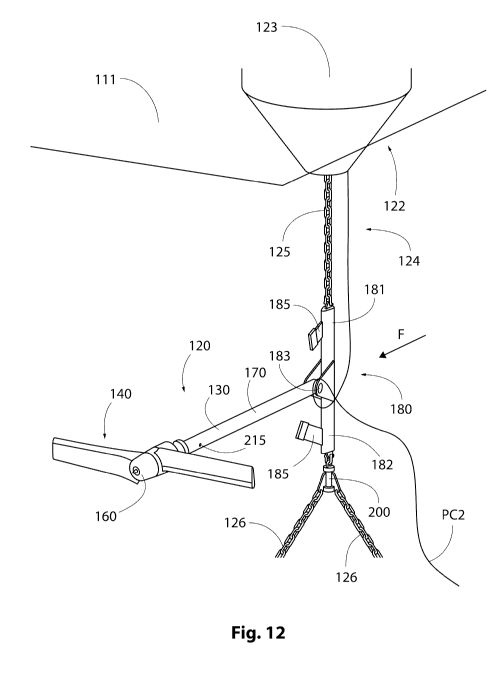
apparatus e.g. 30kW or greater capacity. Figure 12 illustrates a turbine
apparatus 100,
which in the illustrated example is deployed in the sea/ocean. The turbine
apparatus
100 includes a suitably adapted rotor support system 120, which, in the
illustrated
example is connected to a conventional mooring 122, which comprises a
float/buoy 123
floating on the water surface 111 and a mooring chain 124, comprising a down-
chain
125 and anchor chains 126. The mooring chain 124 facilitates locating the
float/buoy
123 in a defined location.
Multiple anchor chains 123 are illustrated in figure 12, but it will be
appreciated that a
mooring comprising a single chain, rope, cable etc. may also be used, for
example, see
figure 13.
Where chains are illustrated in figure 12 or the term 'chain' is used these
may also
indicate instead steel cable, fibre or polymer lines, or a mix of these.
Likewise, the term
down-chain may also be interpreted as referring to a down-line.
The turbine apparatus 100, similar to the turbine apparatus 10 illustrated in
figures Ito
11, includes the rotor support system 120, a rotor mechanism 160, a power take-
off
mechanism 140 and a mounting element 180 operable to connect the turbine
apparatus
100, via the rotor support system 120, to a support structure, which in this
example is
provided by mooring chain 124.
CA 03136261 2021-10-06
WO 2020/212702 PCT/GB2020/050962
In contrast to figures 1 to 11, in the example illustrated in figures 12 to
15, the turbine
apparatus 100 includes the power take-off 160 as part of the rotor mechanism
140.
The rotor support system 120 includes an elongated shaft member 130 and a
buoyancy
adjusting component (balancing mechanism) 170; in the illustrated example the
5 buoyancy adjusting member/balancing mechanism 170 is a shaft-based
buoyancy aid,
which is internal to the elongated shaft 130 as described further below.
In the example illustrated in figures 12 and 13, the mounting element 180
includes a
torque bar assembly 181, which includes a vertical channel or tube section
182, which
in figure 12, replaces a section of the down-chain, or in figure 6b and figure
13 receives
10 a section of the down-chain/down-line 125 within the channel or tube
182, and a
horizontal protruding section 183, which terminates with a clevis-type joint
184. In the
illustrated example, the free second end of the elongated shaft 130 is secured
via the
clevis-type joint 184 to the horizontal protruding section 183; the junction
of the
elongated shaft 130 and the horizontal protruding section 183 facilitates
pitching
15 movement of the turbine apparatus 100; yaw movement is prevented at this
joint and
yaw movement instead occurs through rotation of the apparatus about the long
axis of
the vertical channel or torque bar 181 and down-chain/down-line 125.
In the illustrated example, the axis of the pitching joint and the axis of yaw
movement
are intentionally offset radially from each other by a predetermined distance
which is
20 formed by the length of the horizontal protruding section 183. This acts
to improve the
effectiveness of the torque bar 181 at counteracting turbine operational
torque in a
wider range of conditions, reducing pitching of the torque bar 181 at high
flow velocities.
In the example given the down-chain/down-line 125 and torque bar 181 are
vertical,
however they can also be horizontal (see figure 10) or at an alternative angle
depending
25 on deployment requirements. For example, the torque bar 181 may be
mounted on a
CA 03136261 2021-10-06
WO 2020/212702 PCT/GB2020/050962
31
down-chain/down-line 125 which is provided by a steel cable running diagonally
from
the lower parts of a bridge pile to an upper or above-water part of an
adjacent bridge
pile (not illustrated).
Figure 12 shows the torque bar 11 being removably fixed to the down-chain 125
by pins
or clamps and figure 13 illustrates the torque bar 11 being integrated as part
of the
down-line. Both configurations illustrated in figures 11 and 12 allow yawing
through the
chain/cable/rope/line twisting. In an alternative configuration (see figure
6b) the torque
bar 181is configured to receive the cable/rope/line inside the channel or tube
182 such
that the torque bar can be moved along the down-chain/down-line 125 in either
longitudinal direction to achieve the desired location of the turbine
apparatus 10/100
facilitating free rotation of the torque bar 181 around the longitudinal axis
of the down-
chain/down-line 125 thereby allowing yaw of the turbine apparatus 10, 100
relative to
the down-chin/down-line 125.
In the illustrated example, positioning the torque bar 181 relative to the
down-
chain/down-line 125 is by an actuator or a loop of lines connected to either
end of the
torque bar assembly 181 and looped over pulleys at either end of the down-
chain/down-
line 125. Temporary locking in position may be achieved by suitable latching
of these
lines and/or the torque bar relative to the down-chain/down-line 125.
By way of example, in the bridge pile assembly as described above (not
illustrated) the
mounting arrangement facilitates height adjustment of the turbine apparatus
10, 100
relative water levels and to capture optimum flows during operation. The
arrangement
also facilitates retrieval of the turbine apparatus 10, 100 to a position at
or above water
surface thereby allowing access to the turbine apparatus 10,100 for inspection
or
maintenance.
In the example illustrated in figures 12, 13a and 13b two bump-stops 185
extend from
CA 03136261 2021-10-06
WO 2020/212702
PCT/GB2020/050962
32
the elongated element of the torque bar 181. One bump-stop 185 is located
above the
clevis-type joint 183 and one bump-stop 185 is located below the clevis-type
joint 183.
The bump-stops 185 are positioned such that the pivotal extent of the pitching
movement of the turbine apparatus 10, 100 is restricted within predetermined
limits.
The bump-stops 185 may include a degree of resilience or damping such that
they are
responsive to changing conditions and therefore any risk of damage to the
turbine
apparatus 100, if colliding with the bump-stop is minimised. The bump-stops
185 may
include springs or elastic dampers. In normal use, pitching movement of the
turbine
apparatus 100 relative to the direction of fluid flow should be negligible due
to the
neutral buoyancy status of the turbine assembly 100 plus its elongated design
being
such that it naturally aligns with the direction of fluid flow.
In the illustrated example, see figure 12, the mounting element 180 utilises
an
arrangement of plates and pins which connect to links of the mooring chain 124
to
secure the turbine apparatus 100 to the mooring chain 124. It will be
appreciated, that
alternative fasteners may be adopted, for example one or more clamps or a
combination of different fasteners.
The mounting element 180 forms a physical link/connection between two or more
sections of chain, and is physically connected to these chain sections by, for
example a
yaw rotary joint 200 such that rotation/pivot of the mounting element 180,
hence the
turbine apparatus 10,100 relative to the chain is limited to a predetermined
angular
range, for example 150 degrees. In the example illustrated in figure 12, i.e.
utilising
multiple anchor chains 126, a yaw plate 200 is provided at the junction of the
down-
chain 125 and the anchor chains 126. As illustrated in figure 12, the turbine
apparatus
100 yaws freely about the long axis of the torque bar assembly 181 and down-
chain
125, and the extent of yawing is limited in relation to the yaw plate 200.
CA 03136261 2021-10-06
WO 2020/212702 PCT/GB2020/050962
33
The two opposing anchor chain lengths 126 in the mooring configuration shown
in figure
12 apply opposing tension forces at the yaw plate 200 via connection points on
the plate
which are separated by a specified distance to create a force which tends to
bias
alignment of the plane of the yaw plate 200 to align with the path of the
anchor chains
126. Physically limiting the yaw extents of a turbine apparatus 100 in
relation to the
alignment of this yaw plate 200 can be used to bias or limit yaw of a turbine
apparatus
to only occur around one side of the down-chain 125 during the zero flow
periods within
directionally changing tidal flows. This is achieved by connecting a yawing
part of the
turbine's support to the yaw plate directly or via a short length of down-
chain 125 or via
a rotational coupling capable of limited rotation. The same effect as a yaw
plate can
also be produced by any arrangement which symmetrically connects the two
opposing
anchor chain lengths 126 and the one down chain 125 such that these connection
points are spaced apart.
An anti-rotation post (not illustrated) may extend downward of the yaw plate
200. The
anti-rotation post is operable to help prevent yaw plate rotation and hence
uncontrollable rotation of the turbine apparatus 100 about the long axis of
the down-
chain 125. It does this by ensuring the biasing restoring yaw moment acting on
the
yaw plate 200 remains effective even if greater than 180 degrees of yaw
movement
from the neutral point should occur on the yaw plate.
The yaw plate 200 and the anti-rotation post (when used) promote a yaw
returning force
as a result of tension in the mooring chains 124 and 126. This ensures the
turbine
apparatus always yaws back towards a neutral starting position when the
current slows
to a stop.
In the example illustrated in figure 13a i.e. using a single anchor
chain/chain leg 124', or
when the mounting element 180 is affixed such that it has substantially
unhindered
CA 03136261 2021-10-06
WO 2020/212702 PCT/GB2020/050962
34
freedom to yaw round the axis of a chain leg 124', yaw is controlled via holes
215
provided at the root of the rotor mechanism 140 i.e. the position where the
rotor 140
attaches to the elongated shaft 130.
A bi-directional lateral thruster 215 is provided at this location and water
or gas is
expelled as a jet from the holes at stationary tide flow to control yawing
movement of
the turbine apparatus 100.
The holes are positioned on each side of the horizontal diameter of the body
141 of the
rotor mechanism 140. The thruster or jet 215 is computer controlled based on
measured direction of the turbine apparatus 100 and flow velocity.
Figure 12 illustrates an example of power umbilical PC1 and P02 and the
position of the
rotor mechanism 140 relative to flow direction, as indicated by arrow F.
In the example illustrated in figures 12 to 15, as with the examples
illustrated in figures 1
to 11 efficient transmission and generation of power is optimised due to the
responsiveness of the turbine apparatus 100 to changing flow directions. This
responsiveness of the turbine apparatus 100 is provided by the combination of
a
substantially neutrally buoyant system, active balancing, and yaw control
where the
turbine apparatus 10, 100 has a compliant attitude relative to the support
structure and
the plane of flow.
The neutrally buoyant system comprises an assembly of the rotor mechanism 140
and
the rotor support system 120. Neutrally buoyant, as described above, means the
average density of the turbine apparatus 100 is substantially equal to the
density of the
water in which the turbine apparatus 100 is immersed. Within a reasonable
tolerance,
when mounted as illustrated to the mooring chain 123, the freely articulating
turbine
CA 03136261 2021-10-06
WO 2020/212702
PCT/GB2020/050962
apparatus 100 is configured such that there is no tendency to move upward or
downward due to buoyancy or gravitational forces when left undisturbed.
In the examples illustrated in figures 12 and 13a and 13b, neutral buoyancy
and pitch
angle of the turbine apparatus 100 is established by adjusting buoyancy via
the
5 elongated shaft 130 and the balancing mechanism 170, which is provided
inside the
elongate shaft 130.
The balancing mechanism 170 is arranged to move a mass (see figure 14)
relative to
the elongated shaft 130 i.e. to vary weight distribution within the elongated
shaft 130
such that buoyancy distribution and centre of mass of the turbine apparatus
100 is
10 controlled,
Operating the balancing mechanism is similar to the shaft-based buoyancy aid
24, as
illustrated in figure 8 and figure 9 i.e. the balancing mechanism 170 includes
a movable
mass 172 located inside an air-filled sealed buoyant tube 173, which is
inserted into the
elongated shaft 130.
15 In the examples illustrated in figures 12, 13a and 13b, it will be
appreciated that a
flexible power and communications umbilical PC1, PC2 run from the power take
off and
will most likely follow the mooring chain either upwards to the buoy and/or
downwards
to the seabed depending on where onward power and control equipment is
located. In
certain circumstances, a downward umbilical may pass through a rotary yaw
joint (see
20 figure 12) to avoid it twisting with yaw movement. Yaw control can be
used to avoid this
requirement.
Yaw control is particularly important when there is a downward umbilical
because full
yaw rotation in, for example, changing tidal flow directions, may damage the
umbilical.
In the example illustrated in figure 14, the movable mass 172, an electronic
controller
CA 03136261 2021-10-06
WO 2020/212702 PCT/GB2020/050962
36
174 and a lead screw or translation screw 176 are assembled as part of the
balancing
mechanism 170. In contrast to the example illustrated in figure 8, in the
apparatus
illustrated in figure 14, only the mass 172 moves and all controls are located
to one end
of the tube containing the mass 172 and the lead screw 176. The mass 172 is
placed
relative to rotation of the lead screw or other drive 176. Movement of the
mass 172,
relative to the lead screw 176, adjusts buoyancy distribution of the turbine
apparatus
100 and so is used to regulate its pitch angle. Other drive mechanisms may be
employed, for example ratchet drive, piston, belt drive etc.
The tube 173 can be pulled out of the elongated shaft 130 for servicing when
the rotor
mechanism 140 is removed, and while the tube 173 is pitched upward with its
end at the
water surface level this is easily achieved from a boat or vessel 190. A
handle 175
facilitates removal of the tube 173.
Electronic control allows remote activation and may facilitate automatic
corrections or
tuning adjustment of the pitch angle of the turbine apparatus 100 via an
onboard
microprocessor. The microprocessor incorporates a gravity sensor or gyroscope
177.
Using a software algorithm, the sensor continually determines tilt or attitude
of the
elongated shaft 130 and if this moves outside of targeted limits then it
achieves a
correction by causing movement of the mass along the tube 173 by a calculated
amount
and direction. It may also receive communication from external operators via a
wire,
acoustic signal or tube. When instructed by this means to bring the rotor
assembly to
the surface the algorithm will target a tilt angle which places the rotor
assembly at the
surface. A benefit of automatic tuning is that the turbine apparatus 100 is
responsive to
dropping or rising (pitching) of the turbine apparatus 100 and incremental
movement of
the mass compensates for a rising or falling pitch.
As noted above in respect of figures 1 to 11, automated control provides a
responsive
CA 03136261 2021-10-06
WO 2020/212702 PCT/GB2020/050962
37
turbine apparatus 100, wherein potential changes in buoyancy over long
deployments
are corrected.
The controller may incorporate sensors (not illustrated) including a shaft
pitch angle
sensor. The ability of the controller to actively measure the pitch angle of
the elongated
shaft 130 allows the controller to intelligently adjust the position of the
mass 172
according to an internal algorithm. As noted above, controlling the pitch
angle is useful,
for example, to compensate for mass accrued due to fouling from the water way
in
which the turbine apparatus 100 is deployed, or in estuaries where water
density can
vary over time. The controller may also be configured to provide feedback
regarding at
least the pitch angle of the elongated shaft 130.
In the illustrated example, the turbine apparatus 100 includes a debris sensor
300,
which is operable to detect an object or objects coming towards the rotor end
of the
turbine apparatus 100. This, in combination with an accelerometer or camera on
the
shaft may be used to foresee and then record data from, or to avoid, a
potential collision
event. Also, the data may be used to raise an alarm following a suspected
event in
order that potential rotor damage might be assessed. The controller may
comprise
remote communication functionality, achieved, for example, via a wire, an
external
switch, or by a built-in underwater acoustic modem. In the illustrated
example, a wire
runs from the microprocessor in the buoyancy aid onto the top of the buoy
where a
radio modem is operable to receive commands and transmit data remotely, for
example
to a vessel or on-shore facility. A switch is also connected on the buoy as
part of this so
that servicing boat personnel can use this to trigger the turbine to rise to
the surface.
The electronics within the sealed unit may include the facility to convert
electrical power
from waste heat issued from the power take-off, in order to keep batteries
topped up.
It will be appreciated that such functionality permits buoyancy of the
elongated shaft 130
CA 03136261 2021-10-06
WO 2020/212702 PCT/GB2020/050962
38
to be altered, for example buoyancy adjustment permits the turbine assembly
100 to be
pivoted or raised (if detached from the mooring) by remote control to assist
boat crews
in recovery and maintenance of the turbine apparatus 100.
By providing remote control and feedback, the controller may be operable to
raise an
alarm to a maintenance vessel or to an on-shore facility if one or more
problems are
detected, for example problematic pitch angle, rotational speed, or non-
standard
movement, one or more of which may indicate damage to at least part of the
turbine
apparatus 100.
Figures 13a, 13b, 14 and 15 represent versatility of the turbine apparatus 100
for the
.. purpose of maintenance and/or repair, wherein Figure 13a and 13b show the
turbine
assembly 100 pivoted about the mounted end of the elongated shaft 130 such
that the
rotor mechanism 140 is shifted/floated towards the surface of the water 141.
Figure 13a
and figure 15 show the rotor mechanism 140 detached from the elongated shaft
130.
Figure 13a includes a representation of a vessel 190, for example a boat,
which is
positioned near the mooring 122 to facilitate maintenance, repair or recovery
of the rotor
mechanism 140. The turbine apparatus 100 is adapted to the position
illustrated in
figure 13 by adjusting buoyancy of the turbine apparatus 100 via the internal
balancing
mechanism 170. In this position, it is evident the rotor mechanism 140 is
elevated
towards the surface of the water and is accessible from the vessel 190.
Figure 13a also illustrates the rotor assembly removed from the elongated
shaft 130
and includes a removal tool 191, which facilitates removal of the rotor
mechanism 140
from the elongated shaft 130 and retrieval of the rotor assembly 140 from the
vessel
190.
.. Figure 13a illustrates versatility of the turbine apparatus 100, where the
lower section of
CA 03136261 2021-10-06
WO 2020/212702
PCT/GB2020/050962
39
figure 13a illustrates an in-series arrangement of two turbine apparatus 100
and an
upper section includes a single turbine apparatus 100 extending from a single
mooring
line 124' extending down from a buoy 123.
Figure 13a illustrtaes an example of how the position of the turbine apparatus
100
relative to the tether/mooring line 124' can be adjusted utilising a rope and
pulley
system 311 and a winder and lock 310 to ensure the turbine apparatus id
deployed at
the appropriate depth. Power umbilicals PC1, PC2 carries power and/or
hydraulis fluid
and control signals to the seabed, buoy or both.
Figure 13b, illustrates the turbine apparatus 100 in a parked status. In
certain
circumstances it may be desirable not to use the turbine apparatus 100, but it
may be
necessary to keep the rotor mechanism on the elongated shaft and in the
deployed
location. To protect the apparatus and to prevent unnecessary operation, the
example
in figure 13b illustrates the extent of tilt of the elongate shaft 130 to a
maximum floated
extent, where the rotor mechanism 140 is proximate the mooring buoy. In this
position
the rotor mechanism may be tethered to the buoy 123 via a central towing eye
145 to
hold it securely in this position. It will be appreciated, by lifting the
rotor mechanism
clear of the water operation or loading of the rotor mechanism 140 is
prevented. The
parked position also facilitates a detailed inspection.
Figure 15 represents the rotor mechanism 140 detached from the elongated shaft
130.
In the example illustrated, a latch mechanism 143 facilitates
attaching/locking the rotor
mechanism 140 to the elongated shaft 130 and detaching/releasing the rotor
mechanism 140 from the elongated shaft 130. Power, control and communications
connectors at this interface are also simultaneously released.
To ease retrieval of the rotor mechanism 140 an unlocking spike 146 is
provided for
engagement with a suitable unlocking tool 191 (as illustrated in figure 13a).
A towing
CA 03136261 2021-10-06
WO 2020/212702 PCT/GB2020/050962
eye 145 and a buoyant nose 147 are provided on the free end of the rotor
mechanism
140 to aid towing when the rotor mechanism 140 is released from the elongated
shaft
130. Retrieval of the rotor mechanism 140 is compatible with a small
vessel/boat due to
the towing eye 145 and the buoyant nose 147.
5 The towing eye 145 doubles as an attachment point for a towing line 149
during the
detachment process i.e. to allow a boat operative to come alongside and
stabilise the
turbine assembly 100 during the detachment process. In an example, the towing
line
may have a loop fitted, which is one turbine-blade-length from the free end of
the towing
line 149. This loop 149' is tightened around the end of a turbine blade and
the free end
10 of the towing line 149 is secured at the towing eye 145 (see figure 15).
This ensures
the rotor mechanism 14, 140 can be secured at its blade end for efficient and
safe
towing in a blade-lengthwise direction (see arrow TD).
It will be appreciated removing the rotor mechanism 140 from the elongated
shaft 130
permits access to inside the elongated shaft 130. This means the balancing
15 mechanism/buoyancy adjusting component 170 (see figure 14) is
accessible,
maintainable and possibly removable for repair or replacement (as described
above in
respect of figure 14).
The illustrated example, may be connected to shore via an umbilical, or to
equipment in
the mooring buoy/float 123, with a further umbilical then onwards from there
to the
20 shore. If a power umbilical to shore is not practical then power can be
stored or usefully
utilised by equipment located within the buoy 123. This may include energy
storage in
battery, gas or liquid form, or useful work such as atmospheric carbon dioxide
removal,
ocean cleansing, communications, lighting etc.
Modifications and improvements may be made to the foregoing embodiments within
the
25 scope of the claims defining the invention.
CA 03136261 2021-10-06
WO 2020/212702
PCT/GB2020/050962
41
Whilst specific examples of the present invention have been described above,
it will be
appreciated that departures from the described examples may still fall within
the scope
of the claims defining the invention.