Note: Descriptions are shown in the official language in which they were submitted.
- 1 -
Description
Title: Method for producing non-oriented electrical steel
sheet, method
for producing motor core, and motor core
Technical Field
[0001] This invention relates to a method for producing a
non-oriented
electrical steel sheet, a method for producing a motor core by using the non-
oriented electrical steel sheet, and a motor core made from the non-oriented
electrical steel sheet.
Background Art
[0002] With the growing demand for energy saving in
electric equipment
in recent years, non-oriented electrical steel sheets used in an iron core of
a
rotary appliance (motor core) have been required to be excellent in magnetic
properties. The motor core comprises a fixed stator core and a rotating rotor
core. A HEV-driven motor or the like uses a high-frequency driving power
source to satisfy the recent demand for smaller size and higher output power.
Therefore, a non-oriented electrical steel sheet used in a stator core is
strongly
demanded to have excellent magnetic properties of high magnetic flux density
and low iron loss at a high frequency.
[0003] The revolution number of the motor tends to be
increased to
achieve the smaller size and higher output power, so that a big centrifugal
force is applied to the rotor core of a HEV-driven motor having a large outer
diameter. Also, when the rotor core has a very narrow portion (1 to 2 mm)
called as a bridge portion, a big load is applied to such a portion.
Therefore,
the non-oriented electrical steel sheet used in the rotor core is required to
have
a strength higher than the conventional ones.
[0004] The non-oriented electrical steel sheet used in a
motor core is
desired to be excellent in magnetic properties, and moreover, it is desired to
have a high strength for use in the rotor core and a high magnetic flux
density
and low in iron loss at a high frequency for use in the stator core.
[0005] As mentioned above, the non-oriented electrical
steel sheet is
CA 03137623 2021-11-10
- 2 -
required to have different properties depending on for use in a rotor core and
for use in a stator core, even when used for the same motor core. On the
other hand, it is desirable to take out rotor core material and stator core
material from the same raw steel sheet at the same time and thereafter
5 assemble a rotor core or a stator core by laminating each core material,
from
the viewpoint of increasing the material yield and the like in the production
of
a motor core.
[0006] Patent Literature 1 discloses that a motor core is
produced by
taking out rotor core material and stator core material from the same raw
steel
10 sheet and laminating each material to assemble a rotor core and a stator
core,
and thereafter subjecting only the stator core to a stress-relief annealing.
As
the raw steel sheet, there is proposed a non-oriented electrical steel sheet
having a sheet thickness of 0.15 to 0.35 mm, a yield strength before the
stress-
relief annealing of the steel sheet of not less than 600 M Pa and an iron loss
15 W10/400 after the stress-relief annealing of not more than 20 Wikg.
Citation List
Patent Literature
[0007] Patent Literature 1: J P-A-2008-50686
Summary of Invention
20 Technical Problem
[0008] In the technique disclosed in Patent Literature 1,
however, it is
necessary to reduce impurity elements (Ti, 5, N, V, Nb, Zr, As) contained in
the raw steel sheet to a very low level to promote crystal grain growth in the
stress-relief annealing. Also, this technique has a problem that a high
25 production cost is caused by adding Ni, being high in the raw material
cost,
and conducting skin pass rolling before the stress-relief annealing in order
to
reduce the iron loss.
[0009] The invention is made in consideration of the
above problems and
aims to propose a method for producing a non-oriented electrical steel sheet
30 capable of producing a rotor core with high strength and a stator core
with
excellent magnetic properties after stress-relief annealing from the same raw
material. Moreover, the invention aims to propose a method for producing a
CA 03137623 2021-11-10
- 3 -
motor core by using the non-oriented electrical steel sheet and provide a
motor core made from the non-oriented electrical steel sheet.
Solution to Problem
[0010] The inventors have made various studies focusing on
an influence
5 of the surface nature of a raw steel sheet material upon magnetic
properties of
a non-oriented electrical steel sheet in order to develop a non-oriented
electrical steel sheet that can achieve high strength required for a rotor
core as
well as excellent magnetic properties after stress-relief annealing required
for
a stator core. As a result, it has been found out that the iron loss
properties
10 after the stress-relief annealing are largely improved by properly
adjusting a
ratio of an amount of nitrogen present as AIN (N as AIN) in a surface layer of
the steel sheet after the stress-relief annealing to an amount of nitrogen
present as AIN (N as AIN) in a full sheet thickness. Thus, the inventors have
obtained a knowledge that it is important to suppress nitriding on the raw
steel
15 sheet surface in the stress relief annealing by controlling the Zn
content in the
raw steel sheet to a given range in order to properly adjust the above
nitrogen
amount ratio, whereby the invention has been accomplished.
[0011] The invention based on the above knowledge proposes
a method
for producing a non-oriented electrical steel sheet by subjecting a steel slab
20 having a component composition comprising C: not more than 0.0050 mass%,
Si: 2.8 to 6.5 mass%, Mn: 0.05 to 2.0 mass%, P: not more than 0.10 mass%,
5: not more than 0.0050 mass%, Al: 0.3 to 2 mass%, N: not more than 0.0050
mass%, Zn: 0.0005 to 0,0050 mass%, Ti: not more than 0.0030 mass%, Nb:
not more than 0.0030 mass%, 0: not more than 0,0050 mass%, satisfying Si +
25 Al > 4 mass% and the remainder being Fe and inevitable impurities to a
hot
rolling, a hot-band annealing, a cold rolling and a finish annealing, in which
a
yield stress of the steel sheet after the finish annealing is made to not less
than
480 M Pa.
[0012] The steel slab used in the method for producing a
non-oriented
30 electrical steel sheet according to the invention is characterized in
that Zn and
S contents satisfy the following equation (1):
0.20 < (Zn/65)/(S/32) 5. 0.90 .......................... (1).
CA 03137623 2021-11-10
- 4 -
(0013] Also, the method for producing a non-oriented electrical steel
sheet
according to the invention is characterized in that a soaking temperature in
the
finish annealing is in the range of 700 to 900 C.
[0014] Further, the steel slab used in the method for producing a non-
oriented electrical steel sheet according to the invention is characterized by
containing at least one group selected from the following groups A to D, in
addition to the above component composition:
Group A: one or two selected from Sn: 0.005 to 0.20 mass% and
Sb: 0.005 to 0.20 mass%;
Group B: one or more selected from Ca, Mg and Rare Earth Metal
(REM) by 0.0005 to 0.020 mass% in total;
Group C: one or more selected from Cr, Co, Ni and Cu by 0.01 to
1.0 mass% in total; and
Group D: one or two selected from Mo: 0.001 to 0.1 mass% and W:
0.001 to 0.1 mass%.
[0015] Furthermore, the steel slab used in the method for producing a
non-
oriented electrical steel sheet according to the invention is characterized by
containing another optional element within a range that does not affect the
strength and magnetic properties of the non-oriented electrical steel sheet,
in
addition to the above component composition.
[0016] Also, the invention proposes a method for producing a motor core
comprising
taking out rotor core material and stator core material at the same
time from a non-oriented electrical steel sheet produced by any one of the
aforementioned methods,
laminating the rotor core material to form a rotor core, and
laminating the stator core material followed by a stress-relief
annealing to form a stator core, in which
Date Recue/Date Received 2023-01-17
- 4a -
the steel sheet constituting the stator core is subjected to the stress-
relief annealing so that Ni, N2 and t satisfy the following equation (2):
(t x N2)/((t/10) x Ni} 5.0 (2)
and that an iron loss W10/400 (W/kg) satisfies the following equation (3) in
Date Recue/Date Received 2023-01-17
- 5 -
relation to a sheet thickness t (mm):
W10/400 < 8 + 20 X t ........................... (3), where Ni (mass%) is a
content of
nitrogen present as AIN (N as AIN) in a layer from a one-side surface to 1/20
of a sheet thickness and N2 (mass%) is a content of nitrogen present as AIN in
5 a full sheet thickness (N as AIN) and t (mm) is a sheet thickness of the
steel
sheet.
[0017] The method for producing a motor core according to
the invention
is characterized in that a soaking temperature in the stress-relief annealing
is
in the range of 780 to 950 C, and an atmosphere in the stress-relief annealing
10 is a mixed gas of one or two or more selected from nitrogen gas,
hydrogen gas
and a noble gas and has a nitrogen content of not more than 30 vol% and a
dew point of not higher than -20 C.
[0018] Furthermore, the invention is a motor core
configured with
a rotor core made of a non-oriented electrical steel sheet having a
15 component composition comprising C: not more than 0.0050 mass%, Si: 2.8
to
6.5 mass%, Mn: 0.05 to 2.0 mass%, P: not more than 0.10 mass%, S: not more
than 0.0050 mass /0, Al: 0.3 to 2 mass%, N: not more than 0.0050 mass%, Zn:
0.0005 to 0.0050 mass%, Ti: not more than 0.0030 mass%, Nb: not more than
0.0030 mass%, 0: not more than 0.0050 mass%, satisfying Si + Al > 4 mass%
20 and the remainder being Fe and inevitable impurities and
a stator core made of the same non-oriented electrical steel sheet,
in which
the steel sheet constituting the rotor core has a yield stress of not
less than 480 MPa;
25 Ni, N2 and t of the steel sheet constituting the stator core
satisfy
the following equation (2):
( t x N2)/{(t/10) x 5.0 ... (2), where Ni
(mass%) is a
content of nitrogen present as AIN (N as AIN) in a layer from a one-side
surface to 1/20 of a sheet thickness and N2 (mass%) is a content of nitrogen
30 present as AIN in a full sheet thickness (N as AIN) and t (mm) is a
sheet
thickness of the steel sheet; and
an iron loss W10/400 (W/kg) satisfies the following equation (3) in
CA 03137623 2021-11-10
- 6 -
relation to the sheet thickness t (mm):
W10/400 5.. 8 + 20 x t (3)-
[0019] The non-oriented electrical steel sheet as a raw material of a
motor
core according to the invention is characterized in that Zn and S contents
satisfy
the following equation (1):
0.20 5 (Zn/65)/(S/32) 5 0.90 (1).
[0020] Furthermore, the non-oriented electrical steel sheet as a raw
material of a motor core according to the invention is characterized by
containing at least one group selected from following Groups A to D, in
addition
to the above component composition:
Group A: one or two selected from Sn: 0.005 to 0.20 mass% and
Sb: 0.005 to 0.20 mass%;
Group B: one or more selected from Ca, Mg and REM by 0.0005 to
0.020 mass% in total;
Group C: one or more selected from Cr, Co, Ni and Cu by 0.01 to
1.0 mass% in total; and
Group D: one or two selected from Mo: 0.001 to 0.1 mass% and W:
0.001 to 0.1 mass%.
[0021] Also, the non-oriented electrical steel sheet as a raw material
of a
motor core according to the invention is characterized by containing another
optional element within a range that does not affect the strength and magnetic
properties of the non-oriented electrical steel sheet, in addition to the
above
component composition.
***
[0021a] Various other aspects of the invention are defined hereinafter with
reference to the following preferred embodiments [1] to [11].
Date Recue/Date Received 2023-03-28
- 6a -
[1] A method for producing a non-oriented electrical steel sheet
comprising
subjecting a steel slab having a component composition
comprising C: not more than 0.0050 mass%, Si: 2.8 to 6.5 mass%,
Mn: 0.05 to 2.0 mass%, P: not more than 0.10 mass%, S: not
more than 0.0050 mass%, Al: 0.3 to 2 mass%, N: not more than
0.0050 mass%, Zn: 0.0005 to 0.0050 mass%, Ti: not more than
0.0030 mass%, Nb: not more than 0.0030 mass%, 0: not more
than 0.0050 mass%, satisfying Si + Al ?. 4 mass% and the
remainder being Fe and inevitable impurities to a hot rolling, a hot
band annealing, a cold rolling and a finish annealing,
characterized in that
a yield stress of the steel sheet after the finish annealing
is made to be not less than 480 MPa.
[2] The method for producing a non-oriented electrical steel sheet
according to [1], wherein
the steel slab has Zn and S contents that satisfy the
following equation (1):
0.20 5 (Zn/65) / (S/32) <0.90 (1).
[3] The method for producing a non-oriented electrical steel sheet
according to [1] or [2], wherein
a soaking temperature in the finish annealing is in the
range of 700 to 900 C.
[4] The method for producing a non-oriented electrical steel sheet
according to any one of [1] to [3], wherein
the steel slab contains at least one group selected from the
following Groups A to D, in addition to the above component
composition:
Group A: one or two selected from the group consisting of
Date Recue/Date Received 2023-03-28
- 6b -
Sn: 0.005 to 0.20 mass% and Sb: 0.005 to 0.20 mass%;
Group B: one or more selected from the group consisting
of Ca, Mg and Rare Earth Metal by 0.0005 to 0.020 mass% in
total;
Group C: one or more selected from the group consisting
of Cr, Co, Ni and Cu by 0.01 to 1.0 mass% in total of; and
Group D: one or two selected from the group consisting of
Mc: 0.001 to 0.1 mass% and W: 0.001 to 0.1 mass%.
[5] The method for producing a non-oriented electrical steel sheet
according to any one of [1] to [4], wherein
the steel slab contains not more than 0.10 mass% As
and/or not more than 0.10 mass% Bi.
[6] A method for producing a motor core comprising
taking out a rotor core material and a stator core material
at the same time from a non-oriented electrical steel sheet
produced by the method according to any one of [1] to [5],
laminating the rotor core material to form a rotor core, and
laminating the stator core material followed by a stress-
relief annealing to form a stator core, characterized in that
the steel sheet constituting the stator core is subjected to
the stress-relief annealing so that Ni, N2 and t satisfy the following
equation (2):
(t x N2)/{(t/10) x Ni} ? 5.0 (2)
and that an iron loss W10/400, expressed as W/kg, satisfies the
following equation (3) in relation to the sheet thickness t, in mm,:
W10/400 5 8 + 20 x t (3),
where Ni, in mass%, is a content of nitrogen present as AIN in
a layer from a one-side surface to 1/20 of a sheet thickness and
Date Recue/Date Received 2023-03-28
- 6c -
N2, in mass%, is a content of nitrogen present as AIN in a full
sheet thickness and t, in mm, is a sheet thickness of the steel
sheet.
[7] The method for producing a motor core according to [6], wherein
a soaking temperature in the stress-relief annealing is in
the range of 780 to 950 C and an atmosphere in the stress-relief
annealing is a mixed gas of one or more selected from the group
consisting of nitrogen gas, hydrogen gas and a noble gas, and
has a nitrogen content of not more than 30 vol% and a dew point
of not higher than -20 C.
[8] A motor core constituted with
a rotor core made of a non-oriented electrical steel sheet
having a component composition comprising C: not more than
0.0050 mass%, Si: 2.8 to 6.5 mass%, Mn: 0.05 to 2.0 mass%, P:
not more than 0.10 mass%, S: not more than 0.0050 mass%, Al:
0.3 to 2 mass%, N: not more than 0.0050 mass%, Zn: 0.0005 to
0.0050 mass%, Ti: not more than 0.0030 mass%, Nb: not more
than 0.0030 mass%, 0: not more than 0.0050 mass%, satisfying
Si + Al .?, 4 mass% and the remainder being Fe and inevitable
impurities and
a stator core made of the same non-oriented electrical
steel sheet,
characterized in that
the steel sheet constituting the rotor core has a yield stress
of not less than 480 MPa;
Ni, N2 and tin the steel sheet constituting the stator core
satisfy the following equation (2):
(tx N2)/{(t/10) x Ni} ?. 5.0 (2),
where Ni, in mass%, is a content of nitrogen present as
Date Recue/Date Received 2023-03-28
- 6d -
AIN in a layer from a one-side surface to 1/20 of a sheet thickness
and N2, in mass%, is a content of nitrogen present as AIN in a full
sheet thickness and t, in mm, is a sheet thickness of the steel
sheet; and
an iron loss W10/400, expressed as W/kg, satisfies the
following equation (3) in relation to the sheet thickness t, in mm:
W10/400 5 8 + 20 x t (3).
[9] The motor core according to [8], wherein
the non-oriented electrical steel sheet has Zn and S
contents satisfying the following equation (1):
0.20 5 (Zn/65)/(S/32) 5 0.90 (1).
[10] The motor core according to [8] or [9], wherein the non-oriented
electrical steel sheet contains at least one group selected from
following Groups A to D in addition to the above component
composition:
Group A: one or two selected from the group consisting of
Sn: 0.005 to 0.20 mass% and Sb: 0.005 to 0.20 mass%;
Group B: one or more selected from the group consisting
of Ca, Mg and Rare Earth Metal by 0.0005 to 0.020 mass% in
total;
Group C: one or more selected from the group consisting
of Cr, Co, Ni and Cu by 0.01 to 1.0 mass% in total; and
Group D: one or two selected from the group consisting of
Mo: 0.001 to 0.1 mass% and W: 0.001 to 0.1 mass%.
[11] The motor core according to any one of [8] to [10], wherein
the non-oriented electrical steel sheet contains not more
than 0.10 mass% As and/or not more than 0.10 mass% Bi.
Advantageous Effects of Invention
Date Recue/Date Received 2023-03-28
- 6e -
[0022] The invention can produce a non-oriented electrical steel sheet
being high in strength after finish annealing as well as low in iron loss
after
stress-relief annealing, whereby it is possible to produce a rotor core that
requires high strength and a stator core that requires low iron loss from the
same raw steel material sheet. Accordingly, it is possible to stably provide a
motor core for hybrid electric car, electric car, cleaner, high-speed
generator,
compressor for air conditioner, machine tool and the like.
Brief Description of Drawings
Date Recue/Date Received 2023-03-28
- 7 -
[0023) FIG. 1 is a graph showing an influence of a Zn
content upon an
iron loss W10/400 after stress-relief annealing.
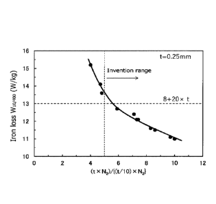
FIG. 2 is a graph showing an influence of a ratio of the nitrogen
amount present as AIN in a surface layer and the nitrogen amount in a full
5 sheet thickness of a steel sheet after stress-relief annealing upon an
iron loss
W10/400 after stress-relief annealing.
FIG. 3 is a graph showing an influence of an atomic ratio of Zn and
S {(Zni65)/(S/ 32)) upon an iron IOSS W10/400 after stress-relief annealing.
FIG. 4 is a graph showing an influence of a nitrogen partial
10 pressure upon an iron loss W101400 after stress-relief annealing.
FIG. 5 is a graph showing of a dew point of an atmosphere in
stress-relief annealing upon an iron loss WID/400 after stress-relief
annealing.
Description of Embodiments
[0024] An explanation will be made on experiments that
have led to the
15 invention below,
At first, a finish-annealed steel sheet to be subjected to the
measurement of mechanical properties and magnetic properties is produced by
the following steps:
1. Continuous casting step in which 11 charges of steel having the
20 following component composition are melted in a vacuum melting furnace
and
casted to form a raw steel material;
(Component composition of steel)
C: 0.0025 mass%, Si: 3.5 mass%, Mn: 0.7 mass%, P: 0,01 mass%,
5: 0.0021 mass%, Al: 0.9 mass%, N: 0.0019 mass%, Ti: 0.0011 mass%, Nb:
25 0.0009 mass%, 0: 0.0024 mass% and the remainder being Fe and inevitable
impurities
2. Hot rolling step in which the raw steel material is hot rolled to
form a hot-rolled sheet having a sheet thickness of 2.0 mm;
3. Hot-band annealing step in which the hot-rolled sheet is
30 annealed at 930 C for 30 seconds;
4. Pickling step in which the hot-rolled sheet is pickled after hot-
band annealing;
CA 03137623 2021-11-10
-8-
5. Cold rolling step in which the hot-rolled sheet after the
pickling is formed into a cold-rolled sheet having a sheet thickness of 0.25
mm;
6. Finish annealing step in which the cold-rolled sheet is
5 subjected to a finish annealing in an atmosphere of H2: N2 = 20:80 by
vol% at
800 C for 10 seconds.
[0025] A J IS No. 5 tensile test specimen having a tensile
direction in the
rolling direction is taken out from the steel sheet after the finish annealing
and
subjected to a tensile test according to J IS Z 2241 to measure an upper yield
10 point. Moreover, other test specimens with a length of 180 mm and a
width
of 30 mm are cut out from both the rolling direction (L-direction) and the
direction perpendicular to the rolling direction (C-direction) of the steel
sheet
after the finish annealing and subjected to a heat treatment simulating stress-
relief annealing at 850 C for 1 hour in an atmosphere of N2 = 100 vol%, and
15 an iron loss W101400 thereof in (L+C directions) is measured by an
Epstein test.
[0026] The result shows that there are variations in the
measurement
values of the iron loss. In order to examine the cause thereof, trace
components in each raw steel material (slab) are analyzed, and as a result it
has been confirmed that Zn is contained in the range of 0.0001 to 0.01 mass%.
20 [0027] Table 1 shows a relation between a Zn content and an iron loss
W101400 in the raw steel material, and FIG. 1 is a drawing showing the
relation.
As shown in Table 1 and FIG. 1, the iron loss is confirmed to be reduced when
the Zn content is in the range of 0.0005 to 0.005 mass%. In order to study
the cause of reduction of the iron loss, a section of the steel sheet after
the
25 finish annealing is observed by SEM. As a result, precipitation of fine
Al N
is confirmed within 1/20 of the sheet thickness from the steel sheet surface
of
the test specimens where iron loss has increased, and thus it is presumed that
the precipitation of the fine nitride has increased the iron loss.
CA 03137623 2021-11-10
- 9 -
[0028] Table 1
Zn content Iron loss W10/400
(mass%) (W/kg)
0.0001 14.1
0.0005 12.4
0.0008 12.1
0.0010 11.6
0.0015 11.0
0,0020 11.1
0.0025 11.5
0.0038 12.1
0.0050 12,7
0.0075 13.6
0.0100 15.2
NOM The above steel sheet after the stress-relief
annealing is subjected
to an electrolytic extraction method to analyze the content N1 (mass%) of N
5 present as AIN in a layer within 1/20 of the sheet thickness from the one-
side
surface of the steel sheet and the content N2 (mass%) of N present as AIN in
the full sheet thickness of the steel sheet. Table 2 shows the relation of the
analyzed results and the iron loss, FIG. 2 is a drawing showing Table 2. As
seen from Table 2 and FIG. 2, the iron loss is more reduced as the value of (t
10 x N2)/{(t/10) x N1} being the ratio of the nitrogen amount present as
AIN in
the full sheet thickness of the steel sheet with respect to the nitrogen
amount
present as AIN in the layer within 1/20 of the sheet thickness from the one-
side surface of the steel sheet becomes larger, that is, as the nitriding
degree
in the surface layer of the steel sheet is larger.
CA 03137623 2021-11-10
- 10 -
[0030] Table 2
Iron loss w -10/400
(t X N2)/{(t/10) X N1}
(W/kg)
4.0 15.2
4.7 14.1
4.8 13.6
5.9 12.7
7.1 12.4
7.3 12.1
7.4 12.1
8.3 11.6
8.6 11.5
9.7 11.1
10.0 11.0
[0031] From the above results, the reason for the
reduction of the iron loss
confirmed when the Zn content is in the range of 0.0005 to 0.0050 mass% is
5 considered due to the fact that zinc-based oxide is formed on the steel
sheet
surface by the trace addition of zinc thus to suppress nitriding in the stress-
relief annealing. Moreover, the reason why the iron loss is rather increased
as the Zn content is more increased is considered due to the fact that sulfide
of
Zn is formed and precipitated to increase the iron loss.
10 [0032] As mentioned above, the low iron loss can be sufficiently
achieved
when the Zn content is within the range of 0.0005 to 0.0050 mass%. As
shown in FIGS. 1 and 2, however, there are differences even among the low
iron loss values, and in order to identify the cause of the differences, a
ratio of
Zn to other trace elements has been investigated. As seen from Table 3 and
15 FIG. 3 being a drawing of Table 3, the result shows that the lower iron
loss is
achieved when the Zn and S contents are within a given range.
[0033] Concretely, it is preferable that an atomic ratio
of Zn to 5, or (Zn
/65)/(5/32) satisfies the following equation (1):
0.20 (Zn/65)/(S/32)._ 0.90 ............................. (1).
20 It is supposedly due to the fact that it is difficult to obtain the
effect of
suppressing nitriding by Zn in the case of 0.20 > (Zn/65)/(5/32), as compared
to the case that the ratio is within the above range, while the precipitation
amount of ZnS increases to rather increase the iron loss in the case of
CA 03137623 2021-11-10
- 11 -
(Zn/65)/(S/32) > 0.90.
[0034] Table 3
(Zn/65)/(5/32) Iron loss Wiamoo (W/kg)
0.12 12.4
0.19 12.1
0.23 11.6
0.35 11.0
0.47 11.1
0.59 11.5
0.89 11.8
1.17 12.7
[0035] An examination is made on the influence of an atmosphere, which is
5 considered to largely affect the nitriding in the surface layer of the
steel sheet
in the stress-relief annealing. In this examination, a finish-
annealed steel
sheet to be subjected to the measurement of mechanical properties and
magnetic properties is produced by the following steps:
1. Continuous casting step in which 7 charges of steel having the
10 following component composition are melted in a vacuum melting furnace
and
casted to form a raw steel material;
(Component composition of steel)
C: 0.0026 mass%, Si: 3.6 mass%, Mn: 0.5 mass%, P: 0,01 mass%,
S: 0.0017 mass%, Al: 1.0 mass%, N: 0.0021 mass%, Ti: 0.0013 mass%, Nb:
15 0.0009 mass%, 0: 0.0022 mass%, Zn: 0.0019 mass% and the remainder being
Fe and inevitable impurities
2. Hot rolling step in which the raw steel material is hot rolled to
form a hot-rolled sheet having a sheet thickness of 1.8 mm;
3. Hot-band annealing step in which the hot-rolled sheet is
20 annealed at 920 C for 30 seconds;
4. Pickling step in which the hot-rolled sheet is pickled after the
hot-band annealing;
5. Cold rolling step in which the hot-rolled sheet after the
pickling is formed into a cold-rolled sheet having a sheet thickness of 0.30
25 mm;
CA 03137623 2021-11-10
- 12 -
6. Finish annealing step in which the cold-rolled
sheet is
subjected to a finish annealing in an atmosphere of H2:N2 = 20:80 by vol% at
790 C for 10 seconds.
[0036] A J IS No. 5 tensile test specimen having a tensile
direction in the
5 rolling direction is taken out from the steel sheet after the finish
annealing to
thus measure an upper yield point thereof by a tensile test according to JIS Z
2241, and a value of 560 MPa is obtained. Then, test specimens with a
length of 180 mm and a width of 30 mm are cut out both from the rolling
direction (L-direction) and the direction perpendicular to the rolling
direction
10 (C-direction) of the finish-annealed steel sheet and subjected to a heat
treatment simulating a stress-relief annealing in a mixed atmosphere of
hydrogen and nitrogen at 825 C for 1 hour to measure values of iron loss
W101400 in (L+C) directions by an Epstein test.
In this case, an experiment is
conducted by varying a nitrogen partial pressure within the range of 0 to 100
15 vol% with the dew point (dp) of the mixed atmosphere in the stress-
relief
annealing of -50 C (constant), and also another experiment is conducted by
varying a dew point within the range of -60 to 30 C at a nitrogen partial
pressure of 20 vol% (constant) during the stress relief annealing.
[0037] Table 4 shows a relation between the nitrogen
partial pressure of
20 the atmosphere in the stress-relief annealing and the iron loss after
the stress-
relief annealing. Also, FIG. 4 is a drawing of Table 4. Table 4 and FIG. 4
show that the excellent iron loss properties can be obtained when the nitrogen
partial pressure of the atmosphere in the stress-relief annealing is reduced
to
not more than 30 vol%. This is considered due to the fact that nitriding in
25 the surface layer of the steel sheet is suppressed by reducing the
nitrogen
partial pressure of the atmosphere in the stress-relief annealing to not more
than 30 vol%.
CA 03137623 2021-11-10
- 13 -
[0038] Table 4
Nitrogen partial pressure of
atmosphere in Iron loss
stress-relief annealing W10/400 (W/kg)
(vol%)
100 16.8
80 16.2
70 15.9
50 14.9
10 12.2
0 12.0
[0039] Table 5 shows a relation between the dew point of the atmosphere
in the stress-relief annealing and the iron loss after the stress-relief
annealing.
5 FIG. 5 is a drawing of Table 5. As seen from Table 5 and FIG. 5,
excellent
iron loss properties are obtained when the dew point of the atmosphere in the
stress-relief annealing is set to not higher than -20 C. This is considered
due
to the fact that the formation of a layer of oxide such as A1203 and the like
is
suppressed on the steel sheet surface and the increase of hysteresis loss is
10 suppressed by setting the dew point of the atmosphere in the
stress-relief
annealing to not higher than -20 C.
The invention is accomplished by performing further examinations
based on the above knowledge.
CA 03137623 2021-11-10
- 14 -
[0040] Table 5
Dew point of
Iron loss
an atmosphere in
W101400 (W/kg)
stress-relief annealing ( C)
-60 12.0
-45 12.4
-30 12.8
-20 13.4
0 15.6
10 16.5
30 17.5
[0041] An explanation will be made on the reason for
limiting the
component composition of a non-oriented electrical steel sheet according to
5 the invention below.
C: not more than 0,0050 mass%
C is a harmful element which forms a carbide to cause magnetic
aging and thus deteriorate iron loss properties of a product sheet. Therefore,
it is necessary to limit an upper limit of C contained in a raw steel material
to
10 0.0050 mass%, preferably to not more than 0.0040 mass%. Moreover, the
lower limit of C is not particularly defined, but is preferable to be about
0.0001 mass% from a viewpoint of suppressing decarburization cost in the
steelmaking,
[0042] Si: 2.8 to 6.5 mass%
15 Si has not only an effect of increasing a specific resistance of
steel
to reduce an iron loss but also an effect of increasing a strength of steel by
solid-solution strengthening, and hence it is contained by not less than 2.8
mass%. On the other hand, the Si content exceeding 6.5 mass% makes the
rolling difficult, so that the upper limit is 6.5 mass%.
Preferably, Si is in the
20 range of 3.0 to 6.0 mass%.
[0043] Mn: 0.05 to 2.0 mass%
Mn is an element useful for increasing the specific resistance and
strength of steel, like Si. Also, Mn forms a sulfide to thus fix S and
improves hot brittleness, and hence Mn is contained by not less than 0.05
CA 03137623 2021-11-10
- 15 -
mass%. On the other hand, the addition exceeding 2.0 mass% causes slab
cracking and the like and deteriorates the operability in the steel-making,
and
accordingly, the upper limit is set to 2.0 mass%. Preferably, Mn
is in the
range of 0.1 to 1.5 mass%.
5 [0044] P: not more than 0.10 mass%
P is an element which increases the specific resistance and has a
significant effect of reducing eddy current loss. As being excellent in the
solid-solution strengthening ability, P can be properly added. However, the
excessive addition of P causes the deterioration of the cold rolling property,
so
10 that the upper limit is 0.10 mass%, preferably not more than 0.05 mass%.
[0045] 5: not more than 0.0050 mass%
is formed into sulfide to form precipitates and/or inclusion and
deteriorate productivity (hot-rolling property) and magnetic properties of a
product sheet, so that it is preferable to decrease Si as much as possible.
15 Hence, the upper limit of S is 0.0050 mass%, more preferably not more
than
0.0030 mass%.
[0046] Al: 0.3 to 2 mass%
Al has an effect of increasing the specific resistance of steel and
reduce the iron loss, like Si. However, when Al is less than 0.3 mass%, fine
20 nitride is formed and precipitated to deteriorate the iron loss
properties, so
that the lower limit is 0.3 mass%. On the other hand, when the Al content
exceeds 2 mass%, steel is ennbrittled and the rolling is difficult, so that
the
upper limit is 2 mass%. Preferably, Al is in the range of 0.4 to 1,5 mass%.
[0047] N: not more than 0.0050 mass%
25 N is an element that forms a nitride and is precipitated to
deteriorate the magnetic properties, so that the N content is limited to not
more than 0.0050 mass%, preferably to not more than 0.0040 mass%.
[0048] Zn: 0.0005 to 0.0050 mass%
Zn is one of the most important components in the invention and
30 has an effect of suppressing nitriding on the steel sheet surface in the
stress-
relief annealing. Accordingly, Zn is added by not less than 0.0005 mass%.
On the other hand, when Zn is added by more than 0.0050 mass%, sulfide is
CA 03137623 2021-11-10
- 16 -
formed and precipitated, rather causing an increase in the iron loss.
Therefore, the Zn content is limited to not more than 0.0050 mass.
Preferably Zn is in the range of 0,001 to 0.004 mass%.
[0049] Ti: not more than 0.0030 mass%, Nb: not more than
0.0030 mass%
5 Ti and Nb are elements that form fine precipitates to be
precipitated and increase the iron loss. In particular, when each
content
exceeds 0.0030 mass%, the above bad influence becomes remarkable, so that
each content of Ti and Nb is limited to not more than 0.0030 mass%,
preferably not more than 0.0020 mass%.
10 [0050] 0: not more than 0.0050 mass%
0 is an element that forms oxide to deteriorate the magnetic
properties, and thus the 0 content is limited to not more than 0.0050 mass%,
preferably not more than 0.0040 mass%.
[0051] The non-oriented electrical steel sheet according
to the invention is
15 preferable to have an atomic ratio of Zn to S, i.e. (Zn/65)/(S/32)
satisfying
the following equation (1), in addition to the above component composition:
0.20 (Zn/65)/(5/32) 0.90 ................................. (1).
The atomic ratio of Zn to S satisfying the above equation (1) allows the
effect
of suppressing nitriding of Zn to be developed remarkably.
20 [0052] The remainder other than the above components in the non-
oriented electrical steel sheet according to the invention is Fe and
inevitable
impurities. However, the following elements may be contained in addition to
the aforementioned components.
Sn: 0.005 to 0.20 mass%, Sb: 0.005 to 0.20 mass%
25 Sn and Sb have an effect of improving recrystallization texture to
improve the magnetic flux density and iron loss. In order to obtain the above
effect, it is preferable to add each element by not less than 0.005 mass%.
However, the addition exceeding 0.20 mass% causes the above effect to be
saturated. Therefore, it is preferable to add one or two of Sn and Sb in the
30 range of 0.005 to 0.20 mass% each, more preferably 0.01 to 0.1 mass%
each.
[0053] Ca: 0.0005 to 0.020 mass%, Mg: 0,0005 to 0.020
mass% and REM:
0.0005 to 0.020 mass%
CA 03137623 2021-11-10
- 17 -
Ca, Mg, and REM have an effect of forming stable sulfide and
improving the grain growth properties in stress-relief annealing.
In order to
obtain the above effect, it is preferable to add one or more selected from
these
elements by not less than 0.0005 mass% in total. On the other hand, the total
5 addition exceeding 0.020 mass% only causes the above effect to be
saturated,
When one or more of the elements are added, therefore, the total content is
preferable to fall within the range of 0.0005 to 0.020 mass%. More
preferably, it is in the range of 0.001 to 0.008 mass%,
[0054] Cr: 0.01 to 1,0 mass%, Co: 0.01 to 1.0 mass%, Ni:
0.01 to 1.0
10 mass% and Cu: 0.01 to 1.0 mass%
Cr, Co, Ni, and Cu have an effect of increasing specific resistance
of steel to reduce the iron loss and increase the strength of steel. In order
to
obtain the above effect, it is preferable to add one or more selected from Cu,
Co, Ni, and Cr by not less than 0.01 mass% in total. However, the addition
15 exceeding 1,0 mass% brings about the increase in costs. Therefore, these
elements are preferable to be added by 0.01 to 1.0 mass% in total, more
preferably by 0.1 to 0.5 mass% in total.
(0055] Mo: 0.001 to 0.1 mass% and W: 0.001 to 0.1 mass%
Mo and W are elements both effective for suppressing defect (scab)
20 of the steel sheet surface. In particular, the steel sheet according
to the
invention, being a high alloy steel and easily oxidized, tends to cause scab
resulting from surface cracking, at a high incidence rate. However, the
cracking can be suppressed by adding a trace amount of Mo and W which are
elements that increase the high-temperature strength. Such an effect is not
25 sufficient when each content of Mo and W is less than 0.0010 rnass%,
while
the above effect is saturated when it exceeds 0.1 mass%, only leading to
increase in alloying costs. When Mo and W are added, therefore, each
content is preferable to be in the above range. More preferably, each content
is in the range of 0.0050 to 0.050 mass%.
30 [0056] Also, the non-oriented electrical steel sheet according to the
invention may contain an element other than the aforementioned components
in the range that has no bad influence on the strength properties and magnetic
CA 03137623 2021-11-10
- 18 -
properties of the non-oriented electrical steel sheet. The term "has no bad
influence on the strength properties" means that the yield stress after the
finish annealing is not less than 480 MPa when the respective elements are
contained. Also, the term "have no bad influence on the magnetic
5 properties" means that the iron loss W101400 (W/kg) is not less than a
standard
value, which is calculated by the following equation (3)1 when the respective
elements are contained. The components other than the aforementioned ones
include not more than 0,10 mass% As, not more than 0,10 mass% Bi and so
on,
10 [0057] An explanation will be made on a method for producing a non-
oriented electrical steel sheet according to the invention.
A production of a non-oriented electrical steel sheet according to
the invention comprises a series of steps comprising a production step of the
aforementioned raw steel material, a hot rolling step, a hot-band annealing
15 step, a pickling step, a cold rolling step and a finish annealing step.
Each
step will be concretely explained below.
[0058] <Production step of raw steel material>
A raw steel material (slab) used in the production of a non-oriented
electrical steel sheet according to the invention can be produced by melting a
20 steel having the aforementioned component composition conforming to the
invention by a well-known refining process using a converter, an electric
furnace, a vacuum degassing device or the like and then performing a usual
procedure of a continuous casting method or an ingot making-blooming
method, Moreover, a thin slab having a thickness of not more than 100 mm
25 may be produced by a direct casting method.
[0059] <Hot rolling step>
Then, the steel slab is usually hot rolled by a well-known process
under well-known conditions to form a hot-rolled sheet. Moreover, the steel
slab is usually reheated to a given temperature in a heating furnace and then
30 subjected to the hot rolling, but may be subjected to the hot rolling
immediately after the casting without reheating. In the case of using the thin
slab, it may be hot rolled or may proceed to subsequent step without hot
CA 03137623 2021-11-10
- 19 -
rolling.
[0060] <Hot-band annealing step>
A hot-band annealing subsequent to the hot rolling is preferable to
be performed at a soaking temperature in the range of 800 to 1100 C. The
5 effect of the hot-band annealing is small when the soaking temperature is
lower than 800 C, while, when it exceeds 1100 C, crystal grains are
coarsened to promote brittle fracture (sheet breakage) in cold rolling or
become disadvantageous to the production costs. The soaking time is
preferable to be not more than 180 seconds from a viewpoint of ensuring
10 productivity. It is more preferable that the soaking temperature is 850
to
1000 C and the soaking time is not more than 60 seconds.
[0061] <Cold rolling step>
Next, the steel sheet after the hot-band annealing is pickled for
descaling and thereafter subjected to a single cold rolling or two or more
cold
15 rollings having an intermediate annealing between each cold rolling to
form a
cold-rolled sheet having a final sheet thickness. The finish thickness in the
cold rolling (final sheet thickness) is not particularly limited, but is
preferable
to be in the range of 0.1 to 0.35 mm. The productivity lowers when the sheet
thickness is less than 0.1 mm, while the effect of reducing the iron loss is
20 small when the sheet thickness exceeds 0.35 mm.
[0062] <Finish annealing step>
The cold-rolled sheet having the final sheet thickness is then
subjected to a finish annealing. The finish annealing is preferably a
continuous annealing to be performed at a preferable soaking temperature of
25 700 to 900 C for a soaking temperature holding time of 1 to 300 seconds.
When the soaking temperature is lower than 700 C and the soaking time is
less than 1 second, recrystallization is not advanced sufficiently, failing to
obtain not only good magnetic properties but also a sufficient effect of the
shape correction in the continuous annealing. On the other hand, when the
30 soaking temperature exceeds 900 C and the soaking time exceeds 300
seconds, the crystal grain size is coarsened to decrease the strength of the
steel sheet. From a viewpoint of securing the strength after the finish
CA 03137623 2021-11-10
- 20 -
annealing required for a rotor core (yield stress: not less than 480 MPa), it
is
desirable that the finish annealing is performed at a low temperature for a
short time as much as possible within the extent the shape correction can be
conducted. More preferably, the soaking temperature is in the range of 750
5 to 850 C and the soaking time is in the range of 1 to 30 seconds.
[0063] The steel sheet after the finish annealing has a
property that the
yield stress in the tensile test (upper yield point) is not less than 480 MPa.
As mentioned later, when the stress-relief annealing is conducted under
conditions conforming to the present invention, the steel sheet has a feature
10 that the iron loss properties are very excellent.
[0064] In order to secure the insulation property in the
lamination of the
steel sheets, it is preferable to form an insulation coating on the surface of
the
steel sheet after the finish annealing and provide a product sheet (non-
oriented
electrical steel sheet). The insulation coating is desirably an organic
coating
15 containing a resin to secure a good punchability, while it is desirably
a semi-
organic coating or an inorganic coating when the weldability is considered
important.
[0065] An explanation will be made on a motor core
according to the
invention and a method for producing the same below.
20 The motor core according to the invention uses the steel sheet
after
the finish annealing obtained as above as a raw material, and a rotor core
material and a stator core material of a core form are taken out from the
steel
sheet as a raw material by punching or the like at the same time. Thereafter,
the rotor core material is laminated and fixed to assemble a rotor core, and
the
25 stator core material is laminated and fixed to assemble a stator core.
[0066] The rotor core which is required to have a high
strength is used in
the motor core as it is, while the stator core which is required to have
excellent magnetic properties is further subjected to a stress-relief
annealing
to improve the magnetic properties and then used in the motor core. This
30 stress-relief annealing is a very important step in the invention and is
preferable to be conducted under conditions at 780 to 950 C for 0.1 to 10
hours. When the stress-relief annealing temperature is lower than 780 C and
CA 03137623 2021-11-10
- 21 -
the annealing time is less than 0.1 hour, the effect of reducing the iron loss
is
small. On the other hand, when the annealing temperature exceeds 950 C
and the annealing time exceeds 10 hours, it is difficult to secure insulation
among the laminated steel sheets, and the productivity is hindered.
5 [0067] The atmosphere in the stress-relief annealing is also very
important
and is an inert gas atmosphere from a viewpoint of suppressing the nitriding
of the surface layer of the steel sheet. Concretely, it is a mixed gas of one
or
more selected from N2, H2 and a noble gas, and a N2 content in the
atmosphere gas is preferable to be not more than 30 vol%. For example, an
10 atmosphere of H2: N2 = 80:20 as a vol% ratio is preferable. Also, the
dew
point of the atmosphere is preferably not higher than -20 C, more preferably
not higher than -40 C from a viewpoint of preventing oxidation on the steel
sheet surface to reduce the iron loss. Moreover, the atmosphere in the stress-
relief annealing is preferable to be controlled at a temperature zone of not
15 lower than 600 C in the heating, soaking and cooling,
[0068] The steel sheet subjected to the stress-relief
annealing under the
above conditions, that is, the steel sheet configuring the stator core
satisfies
the following equation (2):
(t X N2)/{(t/10) X N1} 5.0 .. (2), where Ni
(mass%) is a
20 content of nitrogen present as AIN (N as AIN) in a layer from a one-side
surface to 1/20 of a sheet thickness and N2 (mass%) is a content of nitrogen
present as AIN in a full sheet thickness (N as AIN) and t (mm) is a sheet
thickness of the steel sheet.
[0069] The equation (2) can be attained by controlling the
Zn content in
25 the raw material steel sheet to a range of 0.0005 to 0.0050 mass%
together
with controlling the nitrogen partial pressure and the dew point of the
atmosphere in the stress-relief annealing to not more than 30 vol% and not
higher than -20 C, respectively, to suppress the nitriding in the surface
layer
of the steel sheet and oxidation on the steel sheet surface.
30 [0070] In the steel sheet that satisfies the equation (2), hysteresis
loss can
be largely decreased by suppressing nitriding in the surface layer of the
steel
sheet and the oxidation on the steel sheet surface in the stress-relief
annealing,
CA 03137623 2021-11-10
- 22 -
and thus the iron loss W10/400 (W/kg) of the steel sheet after the stress-
relief
annealing satisfies the following equation (3) in relation to the sheet
thickness
t (rim):
W10/400 < 8 + 20 x t ........................... (3).
5 When the equation (3) is not satisfied, the heat generation of the stator
core
increases to considerably lower the efficiency of the motor lowers.
Examples
[0071] Each raw steel material (slab) having various
component
compositions shown in Table 6 is heated to a temperature of 1120 C for 30
10 minutes and thereafter hot rolled to form a hot-rolled sheet having a
sheet
thickness of 1.9 mm. The hot-rolled sheet is subjected to a hot-band
annealing at 925 C for 30 seconds, pickled for descaling and cold rolled to
form a cold-rolled sheet having a final sheet thickness shown in Table 7.
Then, the cold-rolled sheet is subjected to a finish annealing under various
15 conditions shown in Table 7 to obtain a finish-annealed sheet,
CA 03137623 2021-11-10
= 23 =
[0012] Table6-1
Component composition (mass%)
(7n/65)
Steel
Remarks
C Si Mn P 5 Al Zn Ti Nb 0 N Sn, Sb Ca,
Mg, REM Cr, Co, Ni, Cu Mo,
(SI32)
1 0,0025 3.6 0,4 0,01 0.0018 0.8
0,0021 0.0011 00009 0.0024 0.0027 Sn:0,03 0.57 Inventive Steel
2 0.0025 3.6 0.4 0.01 0.0018 0.8
0.0021 0.0011 0.0009 0.0024 0.0027 Sn:0.03 0.57 Inventive Steel
3 0.0025 3.6 0.4 0.01 0.0018 0.8
0.0021 0,0011 0.0009 0.0024 0.0027 Sn:0.03 0.57 Inventive Steel
4 0,0025 3.6 0,4 0,01 0.0018 0.8
0,0021 0.0011 0.0009 0.0024 0.0021 Sn:0.03 0.57 Inventive Steel
0.0025 3.6 0.4 0.01 0.0018 0.8 0.0003
0.0011 0.0009 0.0024 0.0027 Sn:0.03 0.08 Comparative Steel
6 0.0025 3,8 0.5 0,01 0.0019 0.6
0.0029 0,0013 0.0011 0.0025 0,0024 0.75 Inventive Steel
7 0.0021 3.8 0,5 0.01 0.0019 0.6
0,0029 0.0013 0.0011 0.0025 0.0024 0.75 Inventive Steel
8 0.0021 3.8 0,5 0.01 0.0019 0.6
0.0029 0.0013 0.0011 0.0025 0.0024 0.75 Inventive Steel
9 0.0021 3,8 0.5 0.01 0.0019 0.6
0.0029 0,0013 0.0011 0.0025 0.0024 0.75 Inventive Steel
0,0021 3.8 0.5 0,01 0.0019 0.6 0,0029
0.0013 0.0011 0,0025 0,0024 0.75 Inventive Steel
11 0.0021 3.8 0.5 0.01 0.0019 0.6
0.0029 0.0013 0.0011 0.0025 0.0024 0.75 Inventive Steel
12 0.0028 3.2 0.8 0.01 0.0024 1.2
0.0024 0,0008 0.0012 0.0021 0.0019 Sn:0.04 0.49 Inventive Steel
13 0,0028 3.2 0,8 0,01 0.0024 1.8
0,0024 0,0008 0.0012 0.0021 0.0020 5n:0,04 0.49 Inventive Steel
14 0.0029 3.5 2.5 0.01 0.0024 0.5
0.0021 0.0008 0.0011 0.0021 0.0028 0.43 Comparative Steel
0.0025 3,3 0.1 0,01 0.0024 2.5 0.0015
0,0008 0.0011 0.0021 0.0021 , 0.31 Comparative Steel
16 0,0019 4.2 0.3 0.01 0.0015 0.3
0,0026 0.0014 0.0012 0.0019 0.0027 Sb:0,01 0.85 Inventive Steel
17 0.0019 5.6 0.3 0.01 0.0015 0.3
0.0027 0.0014 0.0012 0.0019 0.0027 0.89 Inventive Steel
18 0.0022 7.2 0.2 0,01 0.0024 0.3
0.0038 0,0008 0.0011 0.0021 0.0028 0.78 Comparative Steel
19 0,0021 4.0 0,4 0.01 0.0026 0.6
0,0032 0.0011 0.0013 0.0028 0.0024 Sn:0,03 0.61 Inventive Steel
0.0021 4.1 0.4 0.01 0.0026 0.6 0.0032
0.0011 0.0013 0.0028 0.0024 Sn:0.03 0.61 Inventive Steel
21 0.0026 3.2 0.1 0.25 0.0026 1.5
Ø0025.0,0011 0.0013 0.0028 0.0024 Sn:0.06 0.47 Comparative Steel
22 0,0024 3,4 1,2 0,01 0.0019 0.9
0,0024 0,0016 0.0014 0.0027 0,0021 Sm0.03 0.62 Inventive Steel
23 0.0024 3.3 1.8 0.01 0.0019 0.7
0.0024 0.0016 0.0014 0.0027 0.0021 Sn:0.03 0.62 Inventive Steel
24 0,0018 3,5 0.2 0.01 0.0015 0.9
0.0021 0,0012 0.0009 0.0027 0.0021 Sb:0,05 069 Inventive Steel
= 24 =
[0013] Table 6-2
Component composition (mass%) (Zn165)
Steel
1
Remarks
C Si Mc P 5 Al Zn Ti Nb 0 N 5n, 5b Ca, Mgr REM
CrCoNiiCu Mo,
(5132)
25 3.3017 3.6 0.5 001 0.0024 08 00027 00016
0.0014 00027 0.0021 C3:0,0034 0,55 Inventive Steel
26 03017 3.6 0.5 001 0.0026 0.8 00027 0.0016
00014 0.0027 0.0021 Mg:0.0025 0.51 Inventive Steel
27 0.0017 3.6 0,5 3.31 0.0027 0.8 00027 00016
0.0014 0.0027 0.0021 REM:0,0072 0,49 , Inventive Steel
26 0,0025 3,3 0,6 001 0,0059 0,9 0.0019 0,0018 0,0013
0,0029 0,0026 Sn:0,04 0.16 Comparative Steel
29 3.3025 3.8 0.2 0.31 0.0015
0.5 0.0021 0.0041 0.0013 0.0029 0.0026 Sn:0,04 0,69 Comparative Steel
30 0.0025 3.8 0.2 an 0.0015
0,5 00021 0,0007 0.0038 0.0029 0.0026 Sn:0,04 , 0.69 Comparative
Steel
31 3.3025 3.8 0.2 Ea 0.0015
0.5 00021 00007 0.0011 0.0064 0.0026 Sn:0,04 0.69 Comparative Steel
32 0.0025 3.8 0.2 3.31 0.0015 05 00021 3,0007 0.0011
0.0021 0.0065 Sc:0,04 0,69 Comparative Steel
33 0.0021 4.1 0.5 an 0.0023 07
0,0024 00012 0.0013 0.0023 0.0022 Sn:0,03 0.51 Inventive Steel ,
34 00021 4.1 0.5 001
0.0023 07 00024 0.0012 0.0013 0.0023 0,0022 Sn:0,03 0.51 Inventive Steel
35 3.3021 4.1 0.5 031 0.0023
0.7 00024 00012 0,0013 0.0023 0.0022 Sc:0.03 0.51 Inventive Steel
36 0.0026 3.4 0,9 3.31 0.0026
1.4 00019 3.0018 0.0012 0.0021 0.0023 Sc:0.03 0,36 Inventive Steel
37 3,3026 3,4 0,9 001 0,0026 1.4 0.0019 3,0018 0,0012
0,0021 0,0023 Sn:0,03 0.36 Inventive Steel
38 0.0026 3.4 0.9 an 0.0026
1.4 0E9 0.0018 0,0012 0.0021 0.0023 Sc:0.03 0.36 Inventive Steel
39 ,3.0025 3.7 0.8 031 , 0.0021 08 00021, 0.0013
0.0013 0.0032 0.0031 S:0.03 Ca:0,0029 0.49 Inventive Steel
40 3.3024 2.9 0.8 3.308 0.0026 1.6 00034 0.0016
0.0011 0.0028 0.0021 5n:0.03 0.64 Inventive Steel
41 0.0024 3.4 0.6 0.005 0.0021 0.9 00024 00014 0.0014
0.0021 0.0025 Sc:0,01 0,56 Inventive Steel
42 0.0024 3.6 0.4 0.31 0.0018 09
0.0045 0,0014 0.0014 0.0021 0.0025 Sc:0,04 1.23 Inventive Steel
43 3.3329 3.5 0.3 039 0.0019 1.2 00021 0.0011 0.0009
0.0025 0.0024 Sn:0,03 0.54 Inventive Steel
44 0.0028 3.5 0.3 an 0.0019
1.2 00022 00011 0.0009 0.0025 0.0024 Sc:0,03 0,57 Comparative Steel
45 0.0325 3.6 0.4 , 0.01 0.0018 08 0.0007 3,0011 0.0009 0.0024 0.0027 Sn:0,03
019 Inventive Steel
46 0,0325 3,6 0.4 001
0,0037 08 0.0013 00011 0,3009 0,0024 0,0027 Sn:0,03 0.17 Inventive Steel
47 0.0025 3.6 0.4 031 0.0018 08 00041 0.0011 0.3009
0.0024 0.0027 Sn:0,03 1.12 Inventive Steel
48 3.0325 3.6 0,4 031 0.0010 08 00021 00011 0.0009
0.0024 0.0027 Sc:0.03 1,03 Inventive Steel
= 25 =
[0014] Table 6-3
Steel Component composition (mass%)
(705)
Remar(s
C Si Mn P S Al Z Ti Nb 0 N Sn, Sb Ca, Mg,
REM Cr, Co, Ni, Cu Mo, W
(5132)
4900021 3,8 0.5 0,01 0.0019 0.6 0,0029 0,9013 0,0011
0.0025 0,0024 Cr:0,05 0.75 Inventive Steel
5000021 3.6 0.5 0.01 0.0019 0.6 0.0029 0.0013 0.0011
0.0025 0.0024 Cr:0.1 0.75 Inventive Steel
51 0.0021 3.6 0.5 0.01 0.0019 0.6 0.0029 0.0013 0.0011
0.0025 0.0024 Cr:0.5 0,75 Inventive Steel
52 0,0021 3,6 0.5 0,01 0.0019 0.6 0,0029 0,0013 0,0011
0.0025 0,0024 Cr.0,9 0,75 Inventive Steel
53 0.0025 3.6 0.4 0.01 0.0018 0.8 0.0021 0.0011 0.0009
0.0024 0.0027 Co:0.05 0.57 Inventive Steel
54 0.0025 3.6 0.4 0.01 0.0018 , 0.8 0.0021 0.0011 0.0009 0.0024
0.0027 Co:0.1 . 0,57 Inventive Steel
55 0,0025 3.6 0.4 0,01 0.0018 0.8 0,0021 0,0011 0,0009
0.0024 0,0027 Co:0,5 0,57 Inventive Steel
56 0.0025 3.6 0.4 0.01 0.0018 0.8 0.0021 0.0011 0.0009
0.0024 0.0027 Co:0.9 0.57 Inventive Steel
57 0.0028 3.2 0.8 0.01 0.0024 . 1.8 0.0024 0.0008 0.0012 0.0021
0.0020 NI:0.05 0,49 Inventive Steel
58 0,0028 3,2 0.8 0,01 0.0024 1.8 0,0024 0,0008 0,0012
0,0021 0,0020 NI:0,1 0,49 Inventive Steel
59 0.0028 3,2 0.8 0.01 0.0024 1.8 0.0024 0.0008 0.0012
0.0021 0.0020 N1:0.5 0.49 Inventive Steel
60 0.0028 3,2 0.8 0.01., 0.0024 . 1.8 0.0024 0.0008 0.0012 0.0021
0.0020 Ni:0.9 _ 0,49 Inventive Steel
61 0,0029 3,5 0.3 0,09 0.0019 1,2 0,0021 0,0011 0,0009
0.0025 0,0024 Cu.0,05 0,54 Inventive Steel
62 0.0029 3.5 0.3 0.09 0.0019 1.2 0.0021 0.0011 0.0009
0.0025 0.0024 Cu:0,1 0.54 Inventive Steel
63,0.0029 3.5 0.3 0.09, 0.0019 , 1.2 0.0021 , 0.0011 0.0009
0.0025 0.0024 0,54 Inventive Steel
64 0,0029 3,5 0.3 0,09 0.0019 1.2 0,0021 0,0011 0,0009
0.0025 0,0024 Cu:0,05 0,54 Inventive Steel
65 0.0021 3,8 0.5 0,01 0.0019 0.6 0.0029 0.0013 0,0011
0.0025 0.0024 CrØ3, Ni:0,3 0.75 Inventive Steel
66 0.0025 3.6 0.4 0.01 0.0018 0.8 0.0021 0.0011 0.0009
0.0024 0.0027 Co:0.3, Cu:0.3 0,57 Inventive Steel
6100025 3,6 0.4 0,01 0.0018 0.8 0,0021 0,0011 0,0009
0.0024 0,0027 N1Ø3, Cu.0,3 0,57 Inventive Steel
68 0.0025 3.6 0.4 0.01 0.0018 0.8 0.0021 0.0011 0.0009
0.0024 0.0027 Cr:0.3, Cu:0,3 0.57 Inventive Steel
69 Ø0021. 3,6 0.5 Ø01 0.0019 0.6 0.0029 . 0.0013
0.0011 0.0025. 0.0024 . Mo:0,0025 0.75 Inventive Steel
70 0002138 0.5 0.01 0.0019 0.6 0,0029 0,0013 0,0011
0,0025 0.0024 Mo:0,05 0,75 Inventive Steel
71 0.0021 3.6 0.5 0.01 0.0019 0.6 0.0029 0.0013 0.0011
0.0025 0.0024 W:0.0025 0.75 Inventive Steel
72 0.0021 3,6 0.5 0.01 0.0019 0.6 03329 00313 0.0011
0.0025 30324 W:0.05 0,75 Inventive Steel
- 26 -
[0075] A J IS No. 5 tensile test specimen having a tensile
direction in the
rolling direction is taken out from the thus-obtained finish-annealed sheet,
and
a tensile test is conducted according toils Z 2241 to measure an upper yield
5 point.
Also, test specimens with a length of 180 mm and a width of 30
mm are cut out from the rolling direction (L-direction) and the direction
perpendicular to the rolling direction (C-direction) of the finish-annealed
sheet, and subjected to a heat treatment simulating a stress-relief annealing
10 under various conditions shown in Table 7 to measure iron loss Wi0/400
in (L +
C) directions by an Epstein test.
Furthermore, the test specimens after the stress-relief annealing is
subjected to an electrolytic extraction method to measure the content Ni
(mass%) of nitrogen (N as AIN) present as AIN in a layer from one-side
15 surface of the steel sheet to 1/20 of the sheet thickness and the
content N2
(mass%) of nitrogen (N as AIN) forming AIN in the full sheet thickness.
[0076] The measurement results are also shown in Table 7.
As seen from
these results, all the steel sheets that are produced by the raw steel
materials
having the component compositions conforming to the invention under the
20 conditions conforming to the invention have a yield stress after the
finish
annealing of not less than 480 MPa and such excellent iron loss properties
that
the iron loss W10/400 after the stress-relief annealing satisfies the above
equation (3) of the invention.
CA 03137623 2021-11-10
- 27 -
[0077] Table 7-1
Finish
Iron loss
Stress-relief annealing N as AIN in
steel
annealing
after Value in
Final sheet Yield stress after
Ratio of stress- right
Steel Full sheet
thickness finish annealing Atmosphere Dew 1/20 layer
thickness precipitated relief side of Remarks
No. Temp. Time Temp. Time
(MPa) gas point N1
nitrogen annealing equation
N2
t (mm)
(t ) (sec) (t) (hr)
(vol%) ( C)
(mass%) mass% amount W10/400 (3)
()
*1
(W/kg)
1 0.25 800 10 550 850 1 N2:H2=20:80 -55
0.0032 0.0026 8.1 10.6 13.0 Inventive Example
2 0.30 800 10 550 850 1 N2:H2=20:80 -55
0.0029 0.0027 9.3 12.6 14.0 Inventive Example
3 0.20 800 10 550 850 1 N2:H2=20:80 -55
0.0035 0.0028 8.0 10.0 12.0 Inventive Example
_
4 0.15 800 10 - 550 850 - 1 N2:H2=20:80 -55-
0.0037 0.0029 7.8 8.8 11.0 Inventive Example
0.25 800 10 550 850 1 N2:H2=20:80 -55 0.0061
0.0029 4.8 14.5 13.0 Comparative Example
6 0.25 800 10 550 850 1 N2=100 -50 0.0082
0.0031 3.8 15.3 13.0 Comparative Example
7 0.25 780 10 565 825 1 H2=100 -50 0.0024
0.0024 10.0 10.9 13.0 Inventive Example
8 0.20 780 10 565 825 1 Ar=100 -50 0.0024
0.0024 10.0 9/ 12.0 Inventive Example
9 . 0.25 , 780 10 _ 565 825 _ 1 H2=100 -8
0.0071 0.0029 4.1 14.8 13.0 Comparative Example
0.25 1000 10 450 825 _ 2 H2=100 -50 0.0068
0.0029 4.3 11.2 13.0 Inventive Example
11 0.25 750 10 585 800 2 H2:Ar=20:80 -60
0.0024 0.0024 10.0 10.9 13.0 Inventive Example
12 0.27 760 10 535 825 1 H2:Ar=20:80 -50
0.0019 0.0019 10.0 11.2 13.4 Inventive Example
13 0.25 810 10 580 825 1 H2:Ar=20:80 -50
0.0020 0.0020 10.0 10.9 13.0 Inventive Example
14 Unable to produce due to slab cracking -
- - - - Comparative Example
Unable to produce due to slab cracking - -
- - - Comparative Example
16 0.25 850 10 570 900 1 H2=100 -45 0.0027
0.0027 10.0 9.9 13.0 Inventive Example
17 0.25 880 10 600 900 1 H2=100 -45 0.0027
0.0027 10.0 9.1 13.0 Inventive Example
18 Unable to produce due to slab cracking - - - -
- - - - Comparative Example
19 0.30 820 10 580 825 1 N2:H2=10:90 -50
0.0026 0.0024 9.2 11.9 14.0 Inventive Example
0.20 820 10 595 825 1 N2:H2=10:90 -50 0.0026
0.0024 9.2 9.2 12.0 Inventive Example
Unable to produce due to sheet breakage in
21 - - - - - - - - - Comparative Example
cold rolling
22 0.25 810 10 _ 550 850 _ 1 N2:H2=20:80 -55
0.0024 0.0021 8.8 11.0 13.0 Inventive Example
23 0.25 810 10 560 850 1 N2:H2=20:80 -55
0.0025 0.0022 8.8 10.8 13.0 Inventive Example
24 0.27 790 10 530 825 1 N2:H2=10:90 -58
0.0025 0.0022 8.8 11.1 13.4 Inventive Example
*1: (t x N2)/{(t/10) x Ni} = 10 x (N11//N2)
Date Recue/Date Received 2023-01-17
- 28 -
[0078] Table 7-2
Finish
Stress-relief annealing N as AIN in steel Iron loss after
annealing Yield stress
Value in
Final sheet
stress-relief
Steel after finish 1/20 Full sheet
Ratio of right side
thickness Atmosphere Dew
annealing Remarks
No, Temp. Time annealing Temp.Time layer thickness
precipitated of equation
t (mm) gas point
W 10/400
( C) (sec) (MPa) ( C) (hr) N1 N2 nitrogen
(3)
(T) (W/kg)
(mass%) (mass%) amount *1
25 0.25 790 10 540 825 1 N2:H2=10:90 -
60 0.0023 0.0021 9.1 10.3 13.0 Inventive Example
26 0.25 _ 790 10 540 , 825 1 N2:H2=10:90 -60
0.0023 0.0021 9.1 10.3 13.0 Inventive Example
27 0.25 790 10 540 825 1 N2:H2=10:90 -
60 0.0023 0.0021 9.1 10.3 13.0 Inventive Example
28 0.25 820 10 520 820 1 N2:H2=20:80 -
50 0.0027 0.0026 9.6 14.8 13.0 Comparative Example
_
29 - 0.25 - 820 10 545 820 1 N2:H2=20:80 -50 0.0031
0.0027 8.7 16.1 13.0 Comparative Example
30 0.25 820 10 545 820 1 N2:H2=20:80 -
50 0.0035 0.0027 7.7 15.6 13.0 Comparative Example
31 0.25 820 10 545 820 1 .
N2:H2=20:80 -50 0.0036 0.0027 7.5 15.3 13.0
Comparative Example
32 0.25 820 10 545 820 1 .
N2:H2=20:80 -50 0.0081 0.0027 3.3 17.1 13.0
Comparative Example
33 0.20 800 10 595 830 1 Ar=100 -54 0.0022
0.0022 10.0 9.0 12.0 Inventive Example
34 0.25 800 10 595 830 1 H2:Ar=20:80 -
54 0.0025 0.0022 8.8 10.2 13.0 Inventive Example
35 0.30 , 800 10 595 . 830 1 ,
N2:H2=20:80 -54 0.0024 0.0022 9.2 11.5 14.0 Inventive Example
36 0.15 800 10 585 830 1 N2:H2=20:80 -
59 0.0026 0.0022 8.5 8.5 11.0 Inventive Example
37 0.20 800 10 585 900 0.5 Ar=100 -60 0.0023
0.0023 10.0 9.2 12.0 Inventive Example
38 0.25 800 10 585 850 1 N2:H2=10:90 -
55 0.0024 0.0023 9.6 10.4 13.0 Inventive Example
39 0.25 800 10 580 850 2 H2:Ar=10:90 -
55 0.0031 0.0031 10.0 10.5 13.0 Inventive Example
40 0.25 800 10 525 850 1 Ar 0021 . 8 .
9 .=100 -50 0.0027 0 7 10 13.0 Inventive Example
_ _ _
41 . 0.25 -800 10 540 . 825 1 Ar=100 -55 0.0028
0.0025 8.9 10.8 13.0 Inventive Example
42 0.25 800 10 555 850 1 Ar=100 -55 0.0026
0.0025 9.6 12.7 13.0 Inventive Example
43 0.25 800 10 560 850 1 Ar=100 -55 0.0026
0.0024 9.2 10.5 13.0 Inventive Example
Unable to produce due to sheet
44 - - - - - - -
Comparative Example
breakage in cold rolling
45 0.25 800 10 550 850 1 N2:H2=20:80 -
55 0.0038 0.0026 6.8 12.8 13.0 Inventive Example
46 0.25 800 10 550 850 1 N2:H2=20:80 -
55 0.0038 0.0026 6.8 12.4 13.0 Inventive Example
47 0.25 , 800 10 550 , 850 1 ,
N2:H2=20:80 -55 0.0032 0.0026 8.1 12.7 13.0 Inventive Example
48 0.25 800 10 550 850 1 N2:H2=20:80 -
55 0.0032 0.0026 8.1 12.1 13.0 Inventive Example
*1: (t x N2)/{(t/10) x Ni} = 10 x (Ni//N2)
Date Regue/Date Received 2023-01-17
- 29 -
[0079] Table 7-3
Finish
Stress-relief annealing N as AIN in steel
annealing
Final Yield Full sheet
Iron loss after Value in
sheet stress thickness
stress-relief right side
Steel thickness Ratio of
after finish Dew 1/20 layer N*1: (t x
annealing of Remarks
No. Temp. Time annealing Temp. Time
Atmosphere precipitated
t point Ni N2ywno) x
W 10/400 equation
(C) (sec) (CC) (hr) gas (vol%) nitrogen
(mm) (MPa) ( C) (mass%) Ni) = 10 x (W/kg)
(3)
amount *1
(Ni//N2)
(mass%)
49 0.25 780 10 568 825 1 H2=100 -50
0.0024 0.0024 10.0 10.8 13.0 Inventive Example
50 0.25 780 10 570 825 1 H2=100 -50
0.0024 0.0024 10.0 10.7 13.0 Inventive Example
51 0.25 780 10 575 825 1 H2=100 -50
0.0024 0.0024 10.0 10.7 13.0 Inventive Example
52 0.25 780 10 578 825 1 H2=100 -50
0.0024 0.0024 10.0 10.6 13.0 Inventive Example
53 0.30 800 10 552 850 1 N2:H2=20:80 -55
0.0029 0.0027 9.3 12.5 14M Inventive Example
54 0.30 800 10 555 850 1 N2:H2=20:80 -55
0.0029 0.0027 9.3 12.4 14.0 Inventive Example
55 0.30 800 10 557 850 1 N2:H2=20:80 -55
0.0029 0.0027 9.3 12.3 14.0 Inventive Example
56 0.30 800 10 560 850 1 N2:H2=20:80 -55
0.0029 0.0027 9.3 12.3 14M Inventive Example
57 0.25 810 10 585 825 1
H2:Ar=20:80 -50 0.0020 0.0020 10.0 . 10.8 13.0
Inventive Example
58 0.25 810 10 590 825 1
H2:Ar=20:80 -50 0.0020 0M020 10.0 10.7 13.0 Inventive
Example
59 0.25 810 10 600 825 1
H2:Ar=20:80 -50 0.0020 0.0020 10.0 10.6 13.0 Inventive
Example
60 _ 0.25 810 10 , 605 825 1 H2:Ar=20:80
-50 0.0020 _ 0.0020 10.0 , 10.5 13.0 Inventive
Example
61 0.25 800 10 560 850 1 Ar=100 -55
0.0026 0.0024 9.2 10.4 13.0 Inventive Example
62 0.25 800 10 562 850 1 Ar=100 -55
0.0026 0.0024 9.2 10.4 13.0 Inventive Example
63 0.25 800 10 565 850 1 Ar=100 -55
0.0026 0.0024 9.2 10.3 13.0 Inventive Example
64 _ 0.25 800 10 _ 570 850 1 Ar=100 -55
0.0026 0.0024 _ 9.2 10.3 13.0 Inventive Example
65 _ 0.25 780 10 575 825 1 H2=100 -50
0.0024 0.0024 , 10.0 _ 10.6 13.0 , Inventive Example
66 0.30 800 10 560 850 1 N2:H2=20:80 -55
0.0029 0.0027 9.3 12.3 14.0 Inventive Example
67 0.30 800 10 565 850 1 N2:H2=20:80 -55
0.0029 0.0027 9.3 12.3 14.0 Inventive Example
68 0.30 800 10 560 850 1 N2:H2=20:80 -55
0.0029 0.0027 9.3 12.3 14.0 Inventive Example
69 0.25 780 10 565 825 1 H2=100 -50
0.0024 0.0024 10M 10.8 13.0 Inventive Example
70 . 0.25 780 10 565 825 1 H2=100 -50
0.0024 0.0024 10.0 . 10.8 13.0 Inventive Example
71 0.25 780 10 565 825 1 H2=100 -50
0.0024 0.0024 10.0 10.8 13.0 Inventive Example
72 0.25 780 10 565 825 1 H2=100 -50
0.0024 0.0024 10.0 10.8 13.0 Inventive Example
*1: (t x N2)/{(t/10) x Ni} = 10 x (Ni//N2)
Date Recue/Dab3 Received 2023-01-17