Note: Descriptions are shown in the official language in which they were submitted.
WO 2020/251570 PCT/US2019/036807
DENTAL FLOSS DISPENSER
FIELD
[0001] The disclosure relates generally to dental floss
packages, and more
specifically to dental floss packages with floss dispensing mechanisms which
change
the physical property of the dental floss.
BACKGROUND
[0002] Dental floss and dental tape are used to remove plaque
and oral debris
between dental contacts and within the subgingival tissue. While flossing, a
user may
not prefer a dental floss with a smooth surface if the user wants to remove
more plaque
and oral debris. Furthermore, the smooth surface of the floss may not give the
user the
perception that the floss is cleaning during a flossing episode or provide
edges on its
surface to capture plaque and oral debris. Therefore, there is a need for the
surface
roughness and coarseness of the dental floss to be increased.
SUMMARY
[0003] Various disclosed concepts relate to dental floss
cartridges that are
configured to impart textures onto the surface of the floss. According to one
example
("Example 1"), the dental floss cartridge includes a housing, a roll of dental
floss
comprising a polymer such that the dental floss has a first surface and a
second
surface, a floss exit opening in the housing through which the floss is
configured to exit,
a texture-inducing structure arranged within the housing and configured to
impart
texture onto at least one of the first and second surfaces of the dental floss
prior to or
during the dental floss passing through the floss exit opening, and a cutting
device on
an exterior of the housing configured to cut the dental floss into a desired
length.
[0004] According to another example further to Example 1
("Example 2"), the
structure includes at least one roller configured to emboss the texture onto
at least one
of the first and second surfaces of the dental floss as the floss passes over
the at least
one roller.
[0005] According to another example further to Example 2
("Example 3"), the at
least one roller includes a first rotatable roller and a second rotatable
roller in rotational
engagement with the first roller.
[0006] According to another example further to any preceding
Example
("Example 4"), the structure is configured to emboss a three dimensional
pattern onto at
1
CA 03138024 2021- 11- 15
WO 2020/251570
PCT/US2019/036807
least one of the first and second surfaces of the dental floss prior to the
dental floss
passing through the floss exit opening.
[0007] According to another example further to Example 4
("Example 5"), the
three dimensional pattern is a plurality of protrusions and depressions formed
on at
least one of the first and second surfaces of the dental floss in a direction
perpendicular
to a direction in which the floss exits the opening.
[0008] According to another example further to Example 4
("Example 6"), the
three dimensional pattern is a plurality of protrusions and depressions formed
on the at
least one of the first and second surfaces of the dental floss in a direction
perpendicular
to the first and second surfaces.
[0009] According to another example further to Example 4
("Example 7"), the
three dimensional pattern is a plurality of protrusions and depressions formed
on at
least one of the first and second surfaces of the dental floss in an angled
direction with
respect to a direction in which the floss exits the opening.
[00010] According to another example further to Example 4 ("Example 8"), the
three dimensional pattern is a plurality of protrusions and depressions formed
on at
least one of the first and second surfaces of the dental floss in a crisscross
direction.
[00011] According to another example further to any one of the preceding
Examples ("Example 9"), the polymer is expanded polytetrafluoroethylene
(ePTFE).
[00012] According to another example further to any one of the preceding
Examples ("Example 10"), the floss is imbibed with a flavor-inducing chemical.
[00013] According to another example further to any one of the preceding
Examples ("Example 11"), the floss cartridge further includes ingestible
crystal particles
contained within the housing, wherein the texture-inducing structure is
further
configured to embed the ingestible crystal particles into at least one of the
first and
second surfaces of the dental floss.
[00014] According to one example ("Example 12"), a floss cartridge includes a
housing, a roll of dental floss comprising a polymer, the floss having a first
surface and
a second surface, a first rotatable roller and a second rotatable roller in
rotational
engagement with the first roller, at least one of the first roller and the
second roller being
configured to emboss a three dimensional pattern onto at least one of the
first and
second surfaces of the floss, a floss exit opening in said housing through
which the floss
is configured to exit, and a cutting device on an exterior of the housing
configured to cut
the dental floss into a desired length.
2
CA 03138024 2021- 11- 15
WO 2020/251570
PCT/US2019/036807
[00015] According to another example further to Example 12 ("Example 13"), the
first rotatable roller is configured to emboss the three dimensional pattern
onto the first
surface of the floss and the second rotatable roller is configured to emboss
the three
dimensional pattern onto the second surface of the floss.
[00016] According to another example further to Example 12 or 13 ("Example
14"), the floss cartridge further includes a force adjustment device coupled
to the first
and second rotatable rollers to adjust an amount of force exerted by the at
least one of
the first and the second roller onto the at least one of the first and second
surfaces of
the floss.
[00017] According to another example further to any one of Examples 12-14
("Example 15"), the polymer is expanded polytetratluoroethylene (ePTFE).
[00018] According to one example ("Example 16"), a floss cartridge includes a
housing, a non-spinning roll of dental floss comprising a polymer and attached
within
the housing, a floss exit opening in said housing and a cutting device on an
exterior of
the housing configured to cut the dental floss into a desired length. The
dental floss is
configured to dispense from the roll and create a twist in the dental floss.
[00019] According to another example further to Example 16 ("Example 17"), the
floss cartridge further includes a twist-inducing mechanism arranged within
the housing
and configured to induce a twisted configuration to the dental floss prior to
or during the
dental floss passing through the floss exit opening.
[00020] According to another example further to Example 16 or 17 ("Example
18"), the floss exit opening is located proximate to a center of the roll.
[00021] According to another example further to any one of Examples 16-18
("Example 19"), the polymer is expanded polytetrafluoroethylene (ePTFE).
[00022] According to another example further to any one of Examples 16-19
("Example 20"), the floss is imbibed with a flavor-inducing chemical.
[00023] The foregoing Examples are just that and should not be read to limit
or
otherwise narrow the scope of any of the inventive concepts otherwise provided
by the
instant disclosure. While multiple examples are disclosed, still other
embodiments will
become apparent to those skilled in the art from the following detailed
description, which
shows and describes illustrative examples_ Accordingly, the drawings and
detailed
description are to be regarded as illustrative in nature rather than
restrictive in nature.
3
CA 03138024 2021- 11- 15
WO 2020/251570
PCT/US2019/036807
BRIEF DESCRIPTION OF THE DRAWINGS
[00024] The accompanying drawings are included to provide a further
understanding of the disclosure and are incorporated in and constitute a part
of this
specification, illustrate embodiments, and together with the description serve
to explain
the principles of the disclosure.
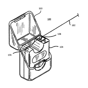
[00025] FIG. 1 is a schematic illustration of a floss dispenser in accordance
with
embodiments described herein;
[00026] FIG. 2 is a schematic illustration of the inside of a texture-inducing
floss
dispenser according to an embodiment described herein;
[00027] FIG. 3 is a schematic illustration of the texture of a floss as
induced in the
floss dispenser of FIG. 2 accordance with embodiments described herein;
[00028] FIGs. 4A-C are schematic illustrations of exemplary patterns of
texture
formed in accordance with embodiments described herein;
[00029] FIG. 5 is a schematic illustration of the inside of a floss dispenser
for
dispensing a twisted floss in accordance with embodiments described herein;
[00030] FIG. 6 is a schematic illustration of the twisted configuration of a
floss as
dispensed by the floss dispenser of FIG. 5 in accordance with embodiments
described
herein;
[00031] FIG_ 7 is a schematic illustration of a partial twist-inducing floss
dispenser
in accordance with embodiments described herein;
[00032] FIG. 8 is a schematic illustration of a twist-inducing mechanism of a
floss
dispenser in accordance with embodiments described herein;
[00033] FIG. 9 is a schematic illustration of a cross section of a gear
element of
the twist-inducing mechanism of FIG. 8;
[00034] FIG. 10 shows the inside of a floss dispenser containing ingestible
crystals in accordance with embodiments described herein; and
[00035] FIG. 11 shows an example floss dispenser with a force adjustment
device in accordance with embodiments described herein.
[00036] Persons skilled in the art will readily appreciate that various
aspects of
the present disclosure can be realized by any number of methods and
apparatuses
configured to perform the intended functions It should also be noted that the
accompanying drawing figures referred to herein are not necessarily drawn to
scale, but
may be exaggerated to illustrate various aspects of the present disclosure,
and in that
regard, the drawing figures should not be construed as limiting.
4
CA 03138024 2021- 11- 15
WO 2020/251570
PCT/US2019/036807
DETAILED DESCRIPTION
Definitions and Terminology
[00037] This disclosure is not meant to be read in a restrictive manner. For
example, the terminology used in the application should be read broadly in the
context
of the meaning those in the field would attribute to such terminology.
[00038] With respect to terminology of inexactitude, the terms "about" and
"approximately" may be used, interchangeably, to refer to a measurement that
includes
the stated measurement and that also includes any measurements that are
reasonably
close to the stated measurement. Measurements that are reasonably close to the
stated measurement deviate from the stated measurement by a reasonably small
amount as understood and readily ascertained by individuals having ordinary
skill in the
relevant arts. Such deviations may be attributable to measurement error or
minor
adjustments made to optimize performance, for example. In the event it is
determined
that individuals having ordinary skill in the relevant arts would not readily
ascertain
values for such reasonably small differences, the terms "about" and
"approximately" can
be understood to mean plus or minus 10% of the stated value.
[00039] Certain terminology is used herein for convenience only. For example,
words such as "proximal," "distal," "top", "bottom", "upper," "lower," "left,"
"right,"
"horizontal," "vertical," "upward," and "downward" describe the relative
configuration
shown in the figures or the orientation of a part in the installed position.
The referenced
components may be oriented in any of a variety of orientations. Similarly,
throughout
this disclosure, where a process or method is shown or described, the method
may be
performed in any order or simultaneously, unless it is clear from the context
that the
method depends on certain actions being performed first.
Description of Various Embodiments
[00040] Various examples are provided of a dental floss dispenser which
changes the texture or the configuration of the dental floss so as to impart
texture.
Floss having texture or a configuration that imparts the feel of texture may
be beneficial
in a number of ways. In certain instances, texturized floss may facilitate
gripping of the
floss when in use In addition, texturized floss may facilitate the removal of
plaque and
debris from teeth. Floss, however, when rolled into a dental floss dispenser
is under
high tension and/or pressure. Due to the tension and pressure, floss having
texture
imparted prior to being arranged within the dental floss dispenser may lose
the
texturization. Floss having too much texture may damage the teeth, gum, or
CA 03138024 2021- 11- 15
WO 2020/251570
PCT/US2019/036807
surrounding tissue. Floss having too little texture or texturized prior to
being placed on a
roll within the dispenser may lose the imparted texture when output Thus,
various
aspects of the present disclosure are directed toward texturizing floss as it
is output to a
user.
[00041] FIG. 1 shows one example of such a dental floss dispenser 100 as seen
from the outside. The dispenser 100 dispenses a dental floss 102 from its
housing 104
through a floss exit opening 106 through which the dental floss 102 exits_ On
the
housing 104 is a cutting device 108 which cuts the dental floss 102 at any
desirable
length as determined by the user. In some embodiments, there is also a lid 110
which
covers the floss exit opening 106 and the cuffing device 108 from outside
elements
when the user is not using the floss. The floss 102 may be an elongated fiber
material
or filament which may be coated with microcrystalline wax prior to being
packaged into
the floss dispenser 100.
[00042] FIG. 2 shows the inside of the floss dispenser 100 according to one
example. The dental floss 102 is contained in a roll or spool 212 that is
fixed in a
rotatable position within the housing 104 such that a user dispenses the floss
102 by
pulling on an outer end 210 of the floss 102. The floss 212 may be rolled, or
otherwise
disposed on a bobbin-like apparatus, and may be placed on a supporting core
208 so
that it may be easily integrated within a suitable dispensing apparatus, such
as the
housing 104 of the floss dispenser 100. Located inside the housing 104
proximate to
the floss exit 106 is a texture-inducing structure 200, which in this example
is a pair of
rollers 201 and 202, that impart a texture to the floss 102 before being used
by the user,
for example by embossing the texture onto at least one surface of the floss
102. The
first roller 201 and the second roller 202 work together to impart the texture
300, as
shown in FIG_ 3, onto the floss 102. For example, the texture 300 can be a
three-
dimensional pattern imparted on one or both of the surfaces 204, 206 of the
floss 102
as further explained below.
[00043] In some examples, the dental floss 102 initially has a flat, sheet-
like
configuration with two sides or surfaces 204 and 206, and the first roller 201
impart a
texture on the first surface 204 of the floss 102 while the second roller 202
induces
another texture on the other, second surface 206_ In certain instances, the
rollers 201,
202 may impart a texture on only one of the surfaces 204, 206. The texture
given to the
first surface 204 may be the same or different from the texture imparted to
the second
surface 206. The supporting core 208 of the roll 212 of floss 102 is rotatably
fixed to the
housing 104 to enable smooth dispensing of the floss 102. In one example, the
two
6
CA 03138024 2021- 11- 15
WO 2020/251570
PCT/US2019/036807
rollers 201 and 202 complement each other such that the first roller 201 has
protrusions
that fit into depressions on the second roller 202, and vice versa. In another
example,
the rollers 201, 202 have staggered protrusions that impact depressions onto
the dental
floss 102 without countering the effects of the other roller.
[00044] In some examples, the rollers 201 and 202 impart the texture prior to
the
floss 102 exiting the housing 104, while in other examples, the texture is
imparted while
the floss 102 passes through the floss exit opening 106_ It should be noted
that
although the examples show two rollers 201 and 202, textures can also be
imparted on
the floss 102 using just one roller, or more than two rollers, such as three
or four rollers,
etc., and such examples are considered to be within the purview of the
disclosure.
Also, various shapes may be implemented for the rollers 201 and 202 is not
particularly
limiting, and may include shapes such as triangular, square, gear-shaped, star-
shaped,
etc., so long as texture is imparted to at least one side of the floss 102.
Furthermore,
the texture-inducing structure 200 arranged within the housing can be a
suitable
structure different from the rollers, such as a non-rotating fixed structure,
so long as the
structure can impart the textures as explained herein. Also, in some examples,
the
rollers 201 and 202 can crush the floss 102 from the sides instead of the
surfaces,
causing the floss 102 to bend or fold onto itself to create creases and / or
additional
texture on the surface_
[00045] Advantages in having textures imparted onto the dental floss 102
include
increased capability for the floss 102 to more effectively remove plaque and
debris from
the spaces between teeth. However, during a typical manufacturing process, the
floss
102 is tightly wrapped around a large spool for ease of transportation from a
facility
which makes the floss 102 to another facility which packages the floss 102
into the
individual containers (e.g the housing 104) to be sold to consumers.
Therefore, when
the floss 102 is being transported, it may be more desirable for the floss 102
to be in a
smooth configuration (i.e., sheet-like configuration) to minimize the volume
of the floss
102 that is wrapped around the large spool. As such, there are benefits in
imparting
texture to the floss 102 within the container (e.g. housing 104) or as the
floss 102 is
dispensed from the container instead of being pre-formed at the time of
manufacture,
because doing so reduces the risk of unwanted abrasion in the floss 102, and
also
because any pre-formed pattern on the floss 102 may be flattened while the
floss 102 is
being transported in the tightly wrapped manner.
[00046] FIGs. 4A, 4B, and 4C show three non-limiting examples of various
patterns for texture 300. FIG. 4A shows an angled pattern 400 which is formed
when
7
CA 03138024 2021- 11- 15
WO 2020/251570
PCT/US2019/036807
the rollers 201, 202 have angled patterns on the surfaces that come into
contact with
the floss 102. FIG. 4B shows a diamond pattern 402 which is formed when the
rollers
201, 202 have diamond or crisscross patterns on such surfaces. Alternatively,
the first
roller 201 can have the angled-pattern surface to impart the angled pattern
400 on one
side of the floss 102, and the second roller 202 can have the same angled-
pattern
surface to impart the angled pattern 400 on the other side of the floss 102,
creating the
diamond pattern 402 FIG_ 4C shows a straight pattern 404 which is formed
similar to
the angled pattern 400. In this example, each of the lines in the straight
pattern 404 is
perpendicular to the direction in which the floss 102 exits the floss exit
opening 106.
[00047] Other suitable patterns can be imparted as appropriate such that the
formation of such patterns improve the floss's debris-removing ability. In
each of the
patterns 400, 402, 404, the lines can represent protrusions, depressions, or
both, in the
surface(s) of the dispensed floss 102. In some examples, a combination of the
patterns
400, 402, 404 can be made. For example, the floss 102 may have a repeating or
alternating pattern of two or more of the textured patterns 400, 402, 404 (or
others)
imparted thereon as the floss 102 is being dispensed from the housing 104.
Other
examples of suitable textures include curvilinear patterns, gravure or dotted
patterns,
and other irregular patterns formed using random displacement of particles
such as
crystals and other microscopic or macroscopic particulates_
[00048] FIG. 5 shows the inside of a floss dispenser 500 according to another
example. The floss 102 is dispensed by pulling an inner end 502 of the roll
212 of floss
102 from the supporting core 208 of the roll 212 and then having the floss 102
exit
through the floss exit opening 106 located in the housing 104. When the floss
102 is
tightly rolled and is stationary, the floss 102 near the supporting core 208
of the roll 212
forms a twisted or helical configuration when dispensed from the housing 104,
as shown
in FIG. 6. Such a twisted configuration can assist in removing more debris
from flossing
compared to a flat, smooth floss due to the texture formed by the twisting of
the floss
102. In this example, the roll 212 of floss 102 is fixed to the housing 104 to
prevent the
roll 212 from rotating as the floss 102 is dispensed. In another example, the
floss 102
can be dispensed by pulling on the outer end 210 of the roll 212 and still
have the
twisted or helical configuration when dispensed if the supporting core 208 is
stationary
as the floss 102 is dispensed.
[00049] In the example shown in FIG. 5, the floss exit opening 106 is located
at
the same position as in FIGs. 1 and 2, i.e., proximate the circumference or
outer portion
of the roll 212 of floss 102. In the example shown in FIG. 7, a floss exit
opening 700 is
8
CA 03138024 2021- 11- 15
WO 2020/251570
PCT/US2019/036807
located proximate the supporting core 208 of the roll 212 of floss 102, such
that the
floss 102 is dispensed by pulling the end of the floss 102 perpendicularly
with respect to
the position of the roll 212 of floss 102, as indicated by the arrow A in FIG.
7. In the
example shown in FIG. 7, a cutting device (not shown) can be placed proximate
the
floss exit opening 700 on the housing 104 or on a lid (not shown) coupled to
the housing
104.
[00050] FIG_ 8 shows a twist-inducing mechanism 800 that can be implemented
in the housing 104 to impart a twisted or helical configuration in the
dispensed floss 102
if the supporting core or a spool portion 806 is allowed to rotate as the
floss 102 is
dispensed. The twist-inducing mechanism 800 has a first gear element 802 which
is
mechanically coupled to a second gear element 804. The floss 102 is wound
around a
spool portion 806 of the first gear element 802. The first gear element 802
rotates
clockwise from the perspective of the figure about an axis defined by the line
C¨C
when the user pulls the floss in the direction shown by the arrow B. This
rotation of the
first gear element 802 causes the second gear element 804 to rotate
counterclockwise
from the perspective of the figure as illustrated by the arrow D. In FIG. 9,
which shows
the cross-section of the second gear element 804 when cut along the line E¨E
as
illustrated, the second gear element 804 includes a slit 900, whose shape
matches the
cross section of the floss 102 and through which the floss 102 passes when
dispensing_
[00051] In one example, the slit 900 is rectangular in shape and the elongated
shape of the slit 900 is dimensioned such that the longer side of the
rectangular shape
defining the slit 900 is the same as or longer than the width of the floss
102, and the
shorter side of the slit 900 is the same as or longer than the thickness of
the floss 102
but shorter than the width of the floss 102. For example, the ratio of the
shorter side to
the longer side may be 1:30, 1:20, 1:15, 1:10, 1:5, etc_, as appropriate. As
such, the
floss 102 is prevented from further rotating within the slit 900, and the
floss 102 rotates
along with the second gear element 804, causing the twisted configuration in
the floss
102. Alternatively, the slit 900 may also incorporate other elongated shapes
such as
oval, diamond, or other suitable shapes that prevents the floss 102 from
rotating within
the slit 900 but allows for the floss 102 to rotate with the slit 900 as the
second gear
element 804 rotates_
[00052] The amount of twist that is imparted can be controlled by varying the
ratio
of the number of teeth in the gear components 802 and 804. The first gear
component
802 has more teeth and a larger diameter than the second gear component 804.
In
some examples, the twist-inducing mechanism 800 is implemented together with
the
9
CA 03138024 2021- 11- 15
WO 2020/251570
PCT/US2019/036807
texture-inducing structure 200 within the housing 104 of the floss dispenser.
For
example, the texture-inducing structure 200 can impart a texture on one or
both of the
surfaces of the floss 102, after which the twist-inducing mechanism 800 twists
the
textured floss to improve the floss's debris-removing ability.
[00053] FIG. 10 shows the inside of a floss dispenser 1000 according to
another
example. In this example, the housing 104 is partially or entirely filled with
crystals 1002
in appropriate ingestible crystal_ Crystals 1002 in addition to the roll 212
of floss 102
and a texture-inducing structure 200, e.g. rollers 201 and 202. The roll 212
of floss 102
in this example is allowed to rotate as the floss 102 is being dispensed from
the floss
exit opening 106. As the floss 102 passes between the rollers 201 and 202, the
crystals
1002 attach themselves to the floss 102, and the rollers 201 and 202 attach,
fix, secure,
set, or partially press these crystals 1002 into the floss 102 during the
process of
imparting texture onto the surfaces of the floss 102. As such, when the floss
102 is
dispensed, the floss 102 not only has texture but also has thereon or therein
a plurality
of crystals 1002 which add additional texture to the surface of the floss 102
to assist
remove debris when using the floss 102. Alternatively, the crystals 1002 may
not attach
themselves to the floss 102 after dispensing, but may only assist in forming
the texture
on the surfaces of the floss 102 before dispensing, such as by causing
abrasion on the
surfaces of the floss 102 to impart such texture_
[00054] In some examples, the ingestible crystal 1002 can be sodium chloride,
sodium bicarbonate, vitamin C, carbamide peroxide, etc., as appropriate. The
crystals
1002 are attached and pressed into the floss 102 to impart a perception of
textures on
the floss. As the floss is used, some of the crystals 1002 may fall out, but
the floss 102
will still feel textured due to the pockets or abrasions left in the surfaces
of the floss 102.
The remaining crystals 1002 that do not fall out but remain on the floss 102
can be
safely ingested by the user. In some examples, the crystals are pressed into
the floss
102 wherein the pressing force is provided by rollers 201 and 202 or by
drawing the
floss 102 through a tapered die. Furthermore, the ingestible crystals 1002 may
include
flavor-inducing chemicals such that the floss 102 is imparted with flavor and
texture as
the floss 102 is dispensed.
[00055] FIG_ 11 shows one example of a dental floss dispenser 1100 with a
force
adjustment device 1102 as seen from the outside. The positions of the rollers
201 and
202 inside the housing 104 are the same as depicted in FIG. 2, i.e. proximate
the floss
exit opening 106, and controlled by the force adjustment device 1102 located
outside
the housing 104. The force adjustment device 1102 is coupled to one or both of
the
CA 03138024 2021- 11- 15
WO 2020/251570
PCT/US2019/036807
rollers 201 and 202 to adjust an amount of force exerted by one or both of the
rollers
201 and 202 onto one or both surfaces of the floss 102. In one example, the
force
adjustment device 1102 is a knob which, when positioned by the user, brings
the rollers
201 and 202 closer together, thereby increasing the force with which the
rollers impart
patterns onto the surface(s) of the floss 102.
[00056] In the above examples, the housing 104 can be formed of a plastic
material and the cutting device 108 can be formed of a metal or other material
suitable
for cutting the floss 102. Similarly, texture-inducing structures, such as the
rollers 201
and 202 as well as the gear elements 802 and 804, can also be made of a
plastic
material or metal. In some examples, the specific plastic material or metal
used in the
texture-inducing structures is determined such that the texture-inducing
property of the
structures is maintained, and the structures are durable enough to properly
operate and
to impart the appropriate textures until at least the entire roll 212 of floss
102 is
dispensed. For example, a typical package of dental floss may be sold in a
roll with
between 40 yards (approximately 36.6 meters) to 60 yards (approximately 54.9
meters).
As such, the material used in the texture-inducing structure may be selected
to ensure
that the structure can withstand at least the length of the floss being
dispensed. In one
example, the texture-inducing structure and the housing are made of a
biodegradable
material such as biodegradable polymers (BDP), a decomposable material, or a
recyclable material.
[00057] The floss 102 can be made of a polymer, examples of which include, but
are not limited to, polytetrafluoroethylene (PTFE) or expanded PTFE (ePTFE).
In some
examples, the floss 102 can be made of other various polymeric (e.g.,
fluoropolymer,
non-fluoropolymer, etc.)) materials such as ultrahigh molecular weight
polyethylene
(UHMWPE), polyamide, polyimide, etc., as known in the art_ In some examples,
the
floss 102 can be imbibed with one or more flavor-inducing chemicals such as
xylitol,
ethyl methylphenylglycidate, isoannyl acetate, ethyl valerate, methyl
anthranilate,
cinnamaldehyde, carvone, vanillin, etc. Furthermore, the flavor-inducing
chemical may
be a taste modifier such as miraculin and curculin.
[00058] Various features have been specifically described in association with
some examples and not in association with others_ It is not the intent,
however, to
preclude the combination of features between examples. Instead, such
combinations
are specifically contemplated and form a part of this disclosure. The
inventive concepts
of this disclosure have been described both generically and with regard to
specific
embodiments. It will be apparent to those skilled in the art that various
modifications
11
CA 03138024 2021- 11- 15
WO 2020/251570
PCT/US2019/036807
and variations can be made in the embodiments without departing from the scope
of the
disclosure. Thus, it is intended that the embodiments cover the modifications
and
variations of this invention provided they come within the scope of the
appended claims
and their equivalents.
12
CA 03138024 2021- 11- 15