Note: Descriptions are shown in the official language in which they were submitted.
CA 03138107 2021-10-26
WO 2020/256735 PCT/US2019/038416
CONTINUOUS EXTRUDED SOLIDS DISCHARGE
BACKGROUND
[0001] As oil and gas well drilling fluids are used, downhole waste solids
accumulate. The
environmentally safe and cost-effective removal of such waste solids is
important to the efficient
operation of oil and gas well drilling systems.
BRIEF DESCRIPTION
[0002] Reference is now made to the following descriptions taken in
conjunction with the
accompanying drawings, in which:
[0003] FIG. 1 presents a schematic view of an illustrative embodiment of an
oil and gas well
drilling system, using a device and method for processing oil or gas well
waste solids in
accordance to embodiments of the disclosure;
[0004] FIG. 2 presents a cross-sectional view of a device for processing oil
or gas well waste
solids including any embodiments of the device used in the oil and gas well
drilling system
disclosed in the context of FIG. 1;
[0005] FIG. 3 presents a perspective view of a portion of an extruder screw
unit of the device for
processing oil or gas well waste solids such as disclosed in the context of
FIGs. 1-2, to illustrate
and define aspects of screw geometry; and
[0006] FIG. 4 presents a schematic flowchart of an illustrative embodiment of
a method for
processing oil or gas well waste solids, including processing solid using any
embodiments of the
device and system disclosed in the context of FIGs. 1-3
DETAILED DESCRIPTION
[0007] The present disclosure relates generally to the field of oil or gas
well waste solids
processing devices and methods, and more specifically, to processes for the
removal and dust
mitigation of waste solids.
[0008] As part of the present disclosure we recognized that the processing of
waste solids can be
facilitated by rewetting treated forms of the waste solids and maintaining the
rewetted treated
solids in a reduced pressure environment while forming a paste. The paste can
then be
discharged into a waste container for removal from a drilling site and
transfer to a landfill site
while minimizing the generation of air-born solid dust can reduce health
hazards to personal at
drilling site and improve the safety of operating equipment at the site.
Moreover, the processing
-1-
CA 03138107 2021-10-26
WO 2020/256735 PCT/US2019/038416
of such waste solids can be a continuous process by using a device that
receives a flow of solids
while maintaining the reduced pressure and wetting the solids to form the
paste and continuously
extrudes the paste as discharge from the device.
[0009] FIG. 1 presents a schematic view an illustrative embodiment of an oil
and gas well
drilling system 100 of the disclosure, the system 100 using any device 101 or
method
embodiments for processing oil or gas well waste solids as disclosed herein.
FIG. 1 generally
depicts a land-based drilling system. Those skilled in the pertinent art would
understand the
system components described herein are equally applicable to water-based
drilling system for
subsea drilling operations employing floating or sea-based platforms and rigs,
without departing
from the scope of the disclosure.
[0010] As illustrated, the drilling system 100 may include a drilling platform
102 that supports a
derrick 104 having a traveling block 106 for raising and lowering a drill
string 105. The drill
string 105 may include, but is not limited to, drill pipe and coiled tubing,
as generally known to
those skilled in the art. A kelly 109 may support the drill string 105 as it
is lowered through a
rotary table 107. A drill bit 108 may be attached to the distal end of the
drill string 105 and may
be driven either by a downhole motor and/or via rotation of the drill string
105 from the well
surface. The drill bit 108 may include, but is not limited to, roller cone
bits, polycrystalline
diamond compact (PDC) bits, natural diamond bits, any hole openers, reamers,
coring bits, etc.
As the drill bit 108 rotates, it may create a wellbore 110 that penetrates
various subterranean
formations 112.
[0011] One or more pumps 114 (e.g., a mud pump) and reservoirs 116 (e.g., a
mud pit) of the
system 100 can provide an oil or gas well drilling fluid 122. For instance,
the fluid 122 can
include constituents such as drilling mud or oil-based slurry compositions
include oil, water and
solids, or other fluids, as familiar to those skilled in the pertinent art.
The pump 114 can circulate
the fluid 122 through flow conduits 124 to the kelly 109, which in turn
conveys the fluid 122
downhole through the interior of the drill string 105 and through one or more
orifices in the drill
bit 108. The fluid 122 may then be circulated back to the surface via an
annulus 126 defined
between the drill string 105 and the walls of the wellbore 110.
[0012] At the surface, the fluid 122 returning from the well bore 110 may exit
the annulus 126
and be conveyed to the fluid processing unit 128 via an interconnecting flow
line 130. The fluid
processing unit 128 may include, but is not limited to, a shaker unit to
facilitate separating the oil
-2-
CA 03138107 2021-10-26
WO 2020/256735 PCT/US2019/038416
or gas well drilling fluids into a phase of liquid 132 and a phase of waste
solids 134. The shaker
unit can include one or more vibrating sieves with a wire-cloth screen
configured to vibrate
while the returning oil or gas well drilling fluids 122 flows on top of it
such that components of
the fluid 122 that are smaller than the wire mesh pass through the screen
(e.g., number 150, 200
and/or 300 screen sizes) as the phase of liquid 132, while the phase of waste
solids 134 includes
the components that are retained by the wire mesh. As familiar to those
skilled in pertinent arts,
some embodiments of the fluid processing unit 128 can further include
centrifuges, separators,
desilters, desanders, or filters to facilitate the further separation into the
liquid and waste solid
132, 134.
[0013] The liquid 132 can be transported from the fluid processing unit 128 to
the reservoir 116
for reuse as part of the drilling fluid 122 while the waste solid 134 can be
transported to a
thermal extraction unit 136 for further processing to form treated solids 138.
[0014] Additionally, as the liquid phase 132 is recovered and reused as part
the drilling fluid
122, the eventual accumulation of large quantities of ultrafine particles
(e.g., having an average
particle size of 50, 10 or 5 microns or less in some embodiments), often
referred to a low gravity
solids, eventually renders the liquid phase no longer useful as a drilling
fluid. In such cases, the
liquid 132 may then deemed to be a spent drilling fluid and the low gravity
solids in the liquid
132 can be further processed and become part of the waste solids 134
transferred to the thermal
extraction unit 136.
[0015] For instance, the waste solids 134 can be transported via a feed line
140 to the thermal
extraction unit 136 which is configured to treat the waste solids 134 by
extracting valuable
hydrocarbon and water vapor from the waste solids with the reminder forming
treated solids 138.
For instance, the thermal extraction unit 136 can include a thermal extraction
barrel 142
configured to heat and expose the waste solids 134 to a turbulent thin film
flow regime while
maintaining the reduced pressure to facilitate extracting the hydrocarbon and
water vapor from
the waste solids 134.
[0016] The extracted hydrocarbon and water vapor can be transported via vent
tube 144 for
further processing in cyclone separators 146 to further extract the
hydrocarbon and water vapor
which can then be transported to a condenser unit 148. In some embodiments,
the condensed
liquid water or hydrocarbon may be sent to from the condenser unit 148 to the
reservoir 116 for
reuse as part of formulating the drilling fluid 122, e.g., serving as a fluid
premix.
-3-
CA 03138107 2021-10-26
WO 2020/256735 PCT/US2019/038416
[0017] A flow conduit 150 can be connected to transport the treated solids 138
to the device 101,
such as further disclosed in the context or FIG. 2-3 below. The flow conduit
150 can be
connected to directly transport the treated solids 138 from the thermal
extraction unit 136 to the
device 101 while maintaining the reduced pressure. In some embodiments, the
flow conduit can
be additionally connected to transport the treated solid, e.g., solids
remaining in the cyclone
separators 146 after the further extraction of hydrocarbon and water vapor,
from the cyclone
separators 146 to the device 101 while maintaining the reduced pressure.
[0018] Embodiments of the system 100 (or as part some embodiments of the
device 101) can
further include: a container 155 connected to supply liquid water to device
101 (e.g., water 156
via flow conduit 157), an eductor 160 connected (e.g., water vapor 161 via a
vent tube 162) to
remove water vapor generated in the device 101, a condenser (e.g., a second
condenser 165 or
the same condenser 148 as discussed above) connected to receive steam from the
eductor 160
(e.g., water vapor 166 via a vent tube 167) and connected to deliver liquid
water to the container
155 (e.g., via a flow conduit 168), and, a waste container 170 connected to
receive paste 175
discharged (e.g., paste continuously extruded to a feed line 177) from the
device 101.
[0019] The term waste solids, as used herein, refers to solids separated from
drilling fluid that
has returned from a well bore and/or low gravity solid recovered from spent
drilling fluid. As
familiar to those skilled in art, waste solids can include solid particulate
objects, including
limestone, shale, clay, bentonite objects, of all shapes, composition and
morphology present in
drilling fluid and downhole formation cuttings and well as hydrocarbons and
water that resides
on or in such solids. For instance, in some embodiments, the waste solids can
have a
hydrocarbon content of greater than 5 wt% and/or water content of greater than
1 wt%.
[0020] The term treated solids, as used herein, refers waste solids that have
been processed to
extract hydrocarbons and water. For instance, in some embodiments, the waste
solids are
thermally treated in a reduced pressure environment (e.g., as processed in a
thermal extraction
unit 136 and one of more optional cyclone units 146a, 146b to remove
hydrocarbons and water
to form the treated solids. E.g., in some embodiments, the resulting treated
solids have a
hydrocarbon content of 5, 4 or 1 wt% or less or less and a water content of 1
or 0.1 wt% or less.
[0021] The term paste, as used herein, refers to a rehydrated mass of the
treated solids (e.g.,
containing from 5 to 75 wt% water, depending upon the average water
absorptivity of the treated
solids) that forms a soft pliable mixture capable of being continuously
extruded from the device
-4-
CA 03138107 2021-10-26
WO 2020/256735 PCT/US2019/038416
101. In some embodiments, the paste can have a density in a range from about
800 to 2800
kg/m3 or in some embodiments, 800 to 1400, or 1400 to 2200, or 2200 to 2800
kg/m3.
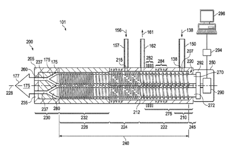
[0022] With continuing reference to FIG. 1 throughout, FIG. 2 presents a cross-
sectional view of
a device 101 for processing oil or gas well waste solids, including any
embodiments of the
device 101 used in the oil and gas well drilling system 101 disclosed in the
context of FIG. 1 or
in the method discussed in the context of FIG. 4.
[0023] The device 101 includes a pressurizing discharge unit 200 having a
casing 205. The
casing 205 includes a solids inlet 207 configured to receive treated solids
138 (e.g., via conduit
150) into a front end 210 of the casing 205. In an internal chamber 212 of the
casing 205 (e.g., an
enclosed chamber sealed to the external environment), the treated solids 138
are exposed to a
reduced pressure of less than atmospheric pressure (e.g., less than 1 atm,
less than 0.9 atm, or
less than 0.8 atm). The pressurizing discharge unit 200 also includes a water
inlet 215configured
to receive water 156 (e.g., via conduit 157) and add the water 156 to the
treated solids 138 in the
internal chamber 212. The pressurizing discharge unit 200 also includes an
extruder screw unit
220, the extruder screw unit 220 having progressive screw sections located
inside the internal
chamber 212 and corresponding to a conveying screw section 222, a mixing screw
section 224
and pressurizing screw section 226.
[0024] The screw conveying section 222 can be configured to convey the treated
solids 138
along a long axis (e.g., axis 228) of the extruder screw unit 220 from the
solids inlet 207 towards
a discharge end 230 of the casing 205 while the reduced pressure is
maintained. The mixing
screw section 224 can be configured to mix the treated solids 138 and the
water 156 together to
form a paste 175. The pressurizing screw section 226 can be configured to
convey the paste 175
towards the discharge end 230 and to generate, in a portion of the casing 232
downstream from
the mixing screw section 224, a backpressure that is greater than atmospheric
pressure (e.g.,
greater than 1 atm, greater than 1.1 atm, or greater than 1.2 atm).
[0025] The pressurizing discharge unit 200 also includes a die assembly 235
configured to
extrude the paste 175 from an orifice (e.g., one or more orifices 237) of the
die assembly 235
located at the discharge end 230 while maintaining the backpressure on the
paste 175 in the
chamber 212.
[0026] One skilled in the pertinent art would appreciate that all three of the
screw sections 222,
224, 226 may be capable of conveying, mixing and pressurizing solids although
the tendencies of
-5-
CA 03138107 2021-10-26
WO 2020/256735 PCT/US2019/038416
these capabilities are configured to be different between the different
section. For instance, the
conveying screw section 222 is capable of conveying a larger unit mass of
treated solid 138 or
paste 175 per unit length and unit time along the long axis 228 than either
the mixing screw
section 224 or the pressurizing screw section 226. The mixing screw section
224 is capable of
forming a homogenous mixture of solid and water more rapidly than either the
conveying screw
section 222 or the pressurizing screw section 226. The pressurizing screw
section 226 is capable
of generating the backpressure more rapidly than either the conveying screw
section 222 or the
mixing screw section 224. The extruder screw unit 220 can have various screw
geometry
arrangements for the different screw sections 222, 224, 226 to achieve the
desired tendencies for
conveying, mixing and pressurization, respectively.
[0027] To facilitate disclosure of certain aspects the extruder screw unit's
220 geometries, FIG. 3
presents a perspective view of a portion of an extruder screw unit 220 of the
device 101 for
processing oil or gas well waste solids such as disclosed in the context of
FIGs. 1-2, to illustrate
and define aspects of screw geometry. The extruder screw unit 220 portion
generally depicted in
FIG. 1 could correspond to any section or portion of the section of the
conveying screw section
222, mixing screw section 224 or pressurizing screw section 226.
[0028] With continuing reference to FIG. 2, as illustrated in FIG. 3, the
arrangement of the screw
sections 222, 224, 226 can be characterized in terms of screw geometry
parameters
corresponding to: pitch length 305, flight depth 310, flight width 315,
helical angle of flight 320,
internal length 325, or, the relative values of these parameters in the
different screw section 222,
224, 226.
[0029] In some embodiments of the extruder screw unit 220, any of the screw
sections 222, 224,
226 can have a pitch length 305 value in a range from 5 to 240 mm, from 10 to
175 mm or from
20 to 100 mm. In some embodiments, the conveying screw section 222 can have a
pitch length
305 that is longer than a pitch length 305 of the mixing screw section 224
(e.g., at least 5, 10,
20, 30, 40 or 50 percent longer), and, that is longer than a pitch length 305
of the pressurizing
screw section 226 (e.g., at least 5, 10, 20, 30, 40 or 50 percent longer),
and, the pitch length 305
of the pressurizing screw section 226 can be longer than the pitch length 305
of the mixing screw
section 224 (e.g., at least 5, 10, 20, 30, 40 or 50 percent longer).
[0030] In some embodiments of the extruder screw unit 220, any of the screw
sections 222, 224,
226 can have a flight depth 310 value in a range from 1 to 40 mm, from 5 to 30
mm or from 8 to
-6-
CA 03138107 2021-10-26
WO 2020/256735 PCT/US2019/038416
20 mm. In some embodiments, the conveying screw section 222 can have a flight
depth 310 that
is deeper than a flight depth 310 of the mixing screw section 224 and that is
deeper than a flight
depth 310 of the pressurizing screw section 226, and, the flight depth 310 of
the mixing screw
section 224 can be deeper than the flight depth 310 of the pressurizing screw
section 226
[0031] In some embodiments of the extruder screw unit 220, any of the screw
sections 222, 224,
226 can have a flight width 315 value in a range from 1 to 20 mm, from 2 to 15
mm or from 3 to
mm. In some embodiments, the conveying screw section 222 can have a flight
width 310 that
is narrower than a flight width 310 of the mixing screw section (e.g., at
least 5, 10, 20, 30, 40 or
50 percent narrower) and that is narrower than a flight width 310 of the
pressurizing screw
section 226 (e.g., at least 5, 10, 20, 30, 40 or 50 percent narrower). In some
embodiments, a
flight width 310 of the mixing screw section 224 can be wider (e.g., at least
5, 10, 20, 30, 40 or
50 percent wider) or narrower (e.g., at least 5, 10, 20, 30, 40 or 50 percent
wider) than the flight
width 310 of the conveying screw section 222 and the flight width 310 of the
pressurizing screw
section 226.
[0032] In some embodiments of the extruder screw unit 220, any of the screw
sections 222, 224,
226 can have a helical angle of flight 320 value in a range from 0 to 90
degrees. In some
embodiments, the conveying screw section 222 can have a helical angle of
flight 320 that is
greater than a helical angle of flight 320 of the pressurizing screw section
226 (e.g., at least 5, 10,
20, 30, 40 or 50 percent greater). In some embodiments, a helical angle of
flight 320 of the
mixing screw section 224 can be greater (e.g., at least 5, 10, 20, 30, 40 or
50 percent greater) or
less (e.g., at least 5, 10, 20, 30, 40 or 50 percent less) than the helical
angle of flight 320 of the
conveying screw section 222 and the helical angle of flight 320 of
pressurizing screw section
226.
[0033] In some embodiments of the extruder screw unit 220, any of the screw
sections 222, 224,
226 can have a number of flights per 1 mm unit length of pitch 305 having a
value in a range
from 1 to 100, from 1 to 50, or from 1 to 2.
[0034] In some embodiments of the extruder screw unit 220, each of the screw
sections 222,
224, 226 can have a constant pitch length 305, flight depth 310, flight width
315 and helical
angle 320 throughout an internal length 325 of the each of the respective
sections 222, 224, 226.
[0035] In some embodiments of the extruder screw unit 220, the conveying screw
section has an
internal length 325 that is in a range from about 50 to 75 percent of a total
length 240 of the
-7-
CA 03138107 2021-10-26
WO 2020/256735 PCT/US2019/038416
extruder screw unit 220 in the internal chamber 212 of the casing 205, the
mixing screw section
224 has an internal length 325 that is in a range from about 12 to 50 percent
of the total length
240 and the mixing screw section has an internal length 325 that is in a range
from about 12 to
50 percent of the total length 240.
[0036] Some embodiments of the extruder screw unit 220 include a single
continuous screw
having the conveying screw section, the mixing screw section, and the
pressurizing screw
section. That is, the extruder screw unit 220 has no non-flight sections along
the entire length of
the extruder screw unit with the exception of embodiments having a first
portion 245 of the
extruder screw unit 220 that is coupled to a drive module 250 configured to
turn the extruder
screw unit.
[0037] In some embodiments, the extruder screw unit 220 includes two or more
continuous
screws (e.g., screws 270, 272) each having parallel internal lengths 225 of
the conveying screw
section 222, the mixing screw section 224, and the pressurizing screw section
226. The screws
can be configured to rotate the same direction, or counter-rotate (rotate in
opposite directions).
In some such embodiments, at least portions of the two or more of the screws
270, 272 are
intermeshed with each other. The term intermeshed, as used herein, refers to
the flights (e.g.,
flight 330, FIG. 3) of one screw extending generally toward the shaft (e.g.,
shaft 335, FIG. 3) of
the other screw and that at least a portion of each flight moves between two
neighboring screw
flights on the other shaft as the shafts rotate. The degree of intermeshing
between the two or
more screws 270, 272 can be another screw geometry parameter to facilitate the
conveying,
mixing and pressurizing tendencies of the screw sections 222, 224, 226. In
some embodiments
of the extruder screw unit 220, a portion of the lengths 325 of any of the
screw sections 222, 224,
226 of one screw 270 that is intermeshed with correspond same screw sections
222, 224, 226 of
the other screw 272 can be a value ranging from 0 to 100 percent, 10 to 90
percent or 20 to 80
percent intermeshed. In some embodiments of the extruder screw unit 220, the
conveying screw
sections 222 of the two or more continuous screws 270, 272 are intermeshed
with each other
(e.g., 100 percent intermeshed), the mixing screw sections 224 are not
intermeshed with each
other (e.g., 0 percent intermeshed) and the pressurizing screw sections 226
are intermeshed with
each other (e.g., 100 percent intermeshed).
[0038] In some embodiments of the device 101, to facilitate extruding the
paste 175 from the
orifice 237 located at the discharge end 230, while maintaining the
backpressure greater than
-8-
CA 03138107 2021-10-26
WO 2020/256735 PCT/US2019/038416
atmospheric pressure on the paste 175, the size of the orifice is reduced
relative to the size of the
internal chamber 212 to thereby restrict the flow of the paste 175. Moreover,
extruding a paste
175 from the orifice 237 facilitates maintaining the reduced pressure in the
portion 275 of the
internal chamber 212 upstream from the mixing screw section 224.
[0039] For instance, in some embodiments, a cross-sectional area of the
internal chamber 212 in
the portion 232 of the casing 205 downstream from the mixing screw section 224
(e.g., the
portion 232 of the casing housing the pressurizing section 226) is greater
than a cross-sectional
area of the orifice (e.g., the sum of the cross-sectional areas of orifices
237). For instance, in
some embodiments, a ratio of the cross-sectional area of the internal chamber
212 located in the
portion 232 of the casing downstream from the mixing screw section 224 to the
cross-sectional
area of the orifice 237 is a value in a range from about 2:1 to 10:1. For
instance, when the total
cross-section area of the orifice 237 equals about 1.6 inch2 (e.g., two
orifices each having a
diameter of 1 inch) then the cross-sectional area of the portion 232 of the
casing can range from
3.2 to 16 inch2 (e.g., the portion 232 internal chamber 212 having a diameter
from 2 to 4.5
inches).
[0040] In some such embodiments, to facilitate adjusting the ratio, the cross-
sectional area of the
orifice 237 can be adjustable. E.g., the die assembly 235 can be configured to
hold die plates
with different sizes of orifice 237 can be swapped in and out of the device
101. Additionally or
alternatively, the die assembly 235 can include a spring-loaded die plate or
pneumatic valve
configured to provide a flow resistance to the flow of paste 175 to thereby to
facilitate generating
the back pressure. For instance, the die assembly 235 can be configured to
include a spring-
loaded or pneumatic valve, e.g., including one or more cavities 260 each
shaped to form a
tapered seat to receive a spring-loaded or pneumatic cone-shaped poppet valve
280. In some
such embodiments, the ratio of the cross-sectional area of the internal
chamber 212 located in the
portion 232 of the casing downstream from the mixing screw section 224 to the
cross-sectional
area of the orifice 237 may be less than 2:1 or equal 1:1.
[0041] Embodiments of the device 101 can include features to mitigate the
formation of steam in
the internal chamber 212 of the casing. Generating steam could negatively
effect maintaining the
reduced pressure in the device 101 and in parts of the system 100 feeding the
treated solids into
the device, e.g., the flow conduits 150, the cyclone separators 146 or the
thermal extraction
barrel 142. For instance, in some embodiments, the casing 205 includes cooling
fins 282 (e.g.,
-9-
CA 03138107 2021-10-26
WO 2020/256735 PCT/US2019/038416
metal fins), or a cooling coil 284 configured circulate a cooling fluid there-
through (e.g., water or
glycol water), to thereby reduce the internal chamber 212 temperature to a
temperature (e.g., less
than 100 C or less than 90 C or less than 80 C) that prevents steam generation
inside the internal
chamber 212. In some embodiments, the cooling coil 284 can be integrated into
walls of the
casing 205 while in other embodiments the cooling coil can be wrapped around
an exterior
surface of the casing 205. In some embodiments, from 10 to 50 percent of a
total length of the
casing 205 as measured from to front end 210 towards the discharge end 230 can
include the
cooling fins 282 and/or the cooling coil 284. Alternatively or additionally,
in some
embodiments, a cooling loop 340 (FIG. 3) configured circulate the cooling
fluid there-through
can be located inside the shaft 335 of one or more of the screws 270, 272 of
the extruder screw
unit 220 (FIG. 2).
[0042] Alternatively or additionally, in some embodiments, to remove steam
that is generated in
the internal chamber 212, the casing 205 can further include a steam outlet
280. In some
embodiments, the steam outlet 288 can be located between the solids inlet 207
and the water
inlet 215. In some embodiments, the steam outlet 288 can be connected (via
vent tube 162) to an
eductor 160, the eductor 160 configured to condense steam exiting the steam
outlet 288 (e.g., by
produce a reduced pressure in the eductor 160).
[0043] Embodiments of the device 101 can further include a drive module 250.
The drive
module 250 can include a motor 290 and gearbox 292 coupled to the extruder
screw unit 220, the
motor 290 configured to rotate screws 270, 272 of the screw unit 220 and the
gear box 292
configured to adjust a rotational speed and rotational direction of the screws
270, 272. In some
embodiments, the drive unit 250 can further include a torque sensor 294
coupled to the motor
290 and configured to measure the torque applied by the motor 290 while
rotating the screws
270, 272. The torque sensor 294 can be configured to convert the measurements
of torque to
digital information which is then transmitted to a computer processor 296 of
the device 101.
Based on the measurements of torque, the computer processor 296 can be
programmed to control
the amount of power used to operate the motor 290 and/or to change a gear of
the gear box 292
to adjust the rotational speed or rotational direction of the screws 270, 272,
e.g., to maintain a
desired backpressure in the internal chamber 212.
[0044] Another embodiment of the disclosure is a method for processing oil or
gas well waste
solids, the method including processing waste solids using any embodiments of
the device 101
-10-
CA 03138107 2021-10-26
WO 2020/256735 PCT/US2019/038416
and system 100 disclosed in the context of FIGs. 1-3. FIG. 4 presents a
schematic flowchart of
an illustrative embodiment of a method 400 for processing oil or gas well
waste solids in
accordance with the disclosure.
[0045] With continuing reference to FIGs. 1-3 throughout, the method 400
includes receiving
treated solids 138 into a solids inlet 207 (step 410), the solids inlet 207
located in a front end 210
of a casing 205 of a pressurizing discharge unit 200, where in an internal
chamber 212 of the
casing 205, the treated solids 138 are exposed to a reduced pressure of less
than atmospheric
pressure.
[0046] The method 400 further includes adding water 156 to the treated solids
138 in the internal
chamber 212 through a water inlet 215 located in the casing 205 (step 420).
[0047] The method 400 also includes rotating an extruder screw unit 220
located in the internal
chamber 212 (step 430). As discussed in the context of FIG. 2, the extruder
screw unit 220 has
progressive screw sections corresponding to a conveying screw section 222, a
mixing screw
section 224 and a pressurizing screw section 226. As part of rotating extruder
screw unit 220
(step 430) the treated solids 138 are conveyed along a long axis length 228 of
the extruder screw
unit 220, by the conveying screw section 222, from the solids inlet 207
towards a discharge end
230 of the casing 205 while the reduced pressure is maintained (step 432), the
treated solids 138
and the water 156 are mixed together, by the mixing screw section 224, to form
a paste 175 (step
434), and, the paste 175 is conveyed towards the discharge end 230 and, in a
portion 232 of the
casing 205 downstream from the mixing screw section 224, a backpressure that
is greater than
atmospheric pressure is generated, by the pressurizing screw section 226 (step
436).
[0048] The method 400 further includes extruding the paste 175 through an
orifice 237 of a die
assembly 235 located at the discharge end 230 of the casing 205 while
maintaining the greater
than atmospheric backpressure on the paste 175 in the internal chamber 212
(step 440).
[0049] Those skilled in the art to which this application relates will
appreciate that other and
further additions, deletions, substitutions and modifications may be made to
the described
embodiments.
-11-