Note: Descriptions are shown in the official language in which they were submitted.
CA 03138173 2021-10-26
WO 2020/191396
PCT/US2020/024190
SYSTEMS AND METHODS FOR ACOUSTICALLY ASSESSING ELECTROLYTE WETTING AND
DISTRIBUTION IN A SECONDARY BATTERY
Cross-reference to Related Applications
[0001] The present Application for Patent claims the benefit of Provisional
Patent Application
No. 62/821,605 entitled "SYSTEMS AND METHODS FOR EVALUATING
ELECTROLYTE WETTING AND DISTRIBUTION" filed March 21, 2019,
expressly incorporated herein by reference in its entirety.
Statement Regarding Federally Sponsored Research or Development
[0002] This invention was made with U.S. Federal government support under
Grant No.
AR0000866 awarded by the Department of Energy, Advanced Research Projects
Agency.
The U.S. Federal government has certain rights in the invention.
Field of Disclosure
[0003] Disclosed aspects are directed to non-invasive and non-destructive
techniques for
evaluating electrolyte characteristics such as wetting and distribution in an
electrochemical system.
Background
[0004] There is a significant and growing pressure on manufacturers of
batteries, such as lithium-
ion batteries (LIBs), to decrease production costs. This pressure is seen to
originate from
rapidly-expanding production capacities worldwide, as well as increased
demands on
battery-driven systems (e.g., electric vehicles) to reduce prices. For
instance, electric
vehicles are expected to drop prices by over 20% to be competent with mass-
market non-
battery-driven vehicles such as internal combustion engine vehicles.
Additionally, the
electric vehicle industry is trending towards larger-size batteries and
thicker, denser
electrodes. However, these trends also lead to the increasing demands on
higher quality,
safety, and reliability of batteries, while continuing to reduce production
costs.
[0005] Looking at production costs in more detail, the final series of
processes steps in the
production of a battery cell, or "cell finishing" as known in the art, can
contribute to about
40% of the total production costs for the battery cells (excluding raw
material costs) in a
typical manufacturing setup. The following steps are generally involved in
battery cell
CA 03138173 2021-10-26
WO 2020/191396
PCT/US2020/024190
2
finishing: electrolyte filling and soaking, pre-charging, formation, aging,
and final end-
of-line quality testing. In particular, the electrolyte filling and soaking
steps are critical to
the overall quality, performance, and safety of the battery cells being
produced, as the
electrolyte is the primary medium through which positive charges flow through
the
battery cell during operation.
[0006] In the electrolyte filling and soaking steps, ensuring a uniform
distribution of electrolyte
is important to battery quality, expected future performance, and safety,
collectively
referred to as battery health. If a battery cell has any areas where the
electrolyte has not
fully saturated or soaked through, i.e., if there is unevenness in the
distribution of
electrolyte, "dry spots" may result in such areas with insufficient
electrolyte. These dry
spots may lead to non-uniform current distribution across the electrode area
during battery
cell formation and operation. In turn, the non-uniform current distribution
can result in
performance degradation of the battery cell (e.g., due to local mechanical
separation or
lithium metal plating). In extreme cases, lithium metal plating in the form of
dendrites
can short-circuit the electrodes internally, and sometimes results in
catastrophic failure in
the form of thermal runaway of the battery cell.
[0007] Under ambient conditions, and even at elevated temperatures, the time
taken for the
electrolyte to be fully distributed throughout a battery cell may be
relatively long,
typically requiring hours of soaking of the electrolyte to achieve a
substantially full
distribution. Electrolyte wetting is mainly driven by capillary forces, which
are typically
not strong enough for liquid electrolytes to completely saturate all the pores
within the
battery cell or a stack of battery cell components. Moreover, saturating the
pores faces
further challenges when the sizes of the pores decrease. Electrolyte
composition and
viscosity can also have a significant influence on electrolyte distribution.
For example, an
electrolyte with lower viscosity may achieve better distribution than an
electrolyte with
higher viscosity. Additionally, if the connectivity of the pore structures in
some regions
is so poor that the electrolyte is faced with restrictions in pathways to flow
through, these
regions may never be wetted. In electrodes, pore size distribution and pore
accessibility
(and thus wetting behavior) are affected by upstream process parameters, such
as the
particle size of constituent electrode materials, thickness of the electrode
layer, carrier
solvent used when casting electrode slurries, speed and temperature during
drying,
compression pressure during calendaring, vacuum drying of electrodes, etc.
Another
reason for long wetting times can be poor wettability of some of the battery
cell
CA 03138173 2021-10-26
WO 2020/191396
PCT/US2020/024190
3
components, based, for example, on poor compatibility between the surface
energies of
the electrolyte and the battery cell components. Poor wettability of this
nature may be
influenced by electrode surface coatings; separator materials, porosity,
coatings, and
treatment; and electrolyte composition, and additives.
[0008] Some electrolyte filling and soaking processes that are currently used
in battery cell
production (as well as during prototyping and process development) to
accelerate the flow
or infiltration of electrolyte into the battery cell include: filling the
battery cells under low
pressure conditions in a vacuum chamber, having multiple fill and vacuum
steps, soaking
under elevated temperatures, press rolling or vibrating during and after
electrolyte filling,
and soaking with additional stack pressure (e.g. where a pouch type cell is
sandwiched
and compressed between flat plates). These conventional methods may
demonstrate a
positive effect on reducing filling and wetting time, but their efficacy has
not been
quantified systematically. There remains a need for non-destructive, scalable
methods for
monitoring, visualizing, and analyzing the dynamic filling and soaking process
of
electrolytes, e.g., in real time, during the course of the dynamic filling and
soaking
process. Such techniques can be useful in ensuring battery health, as well as
in providing
quantitative data for process improvements.
[0009] Currently, assessing the time taken for the electrolyte to be fully
distributed throughout
the battery cell, also referred to as "wetting time," is an empirical,
expensive, and time-
consuming effort. Such assessments typically involve producing a batch of
battery cells,
injecting the batch of battery cells with a known amount of electrolyte, and
sequentially
disassembling subsets of cells of the batch of battery cells after varying
lengths of time
have elapsed since the end of the electrolyte injection. By taking apart the
battery cells,
which is a destructive process, the electrode surfaces can be visually
inspected to
determine the extent of electrolyte wetting. Based on a series of such
destructive tests, an
average wetting time can be estimated, where in some cases a safety factor can
be added
to the average wetting time. The average wetting time (with a safety factor
optionally
added) can be used as the estimated wetting time for battery cells during
large-volume
production of the battery cells.
[0010] Given the dearth of alternative, non-invasive methods for
characterizing the electrolyte
wetting quality in a time-efficient manner, the current techniques (e.g.,
during process
development) involve repeatedly executing the above-described expensive and
time-
consuming processes for determining wetting time for evaluating the influence
of
CA 03138173 2021-10-26
WO 2020/191396
PCT/US2020/024190
4
different material or battery cell components (e.g., a new separator) or
upstream process
parameters (e.g., coating thicker electrode layers) used in the battery cell
production.
[0011] Electrochemical impedance spectroscopy and neutron radiography are
known analytical
methods that have been used to assess electrolyte wetting quality in lithium
ion battery
cells in laboratory settings. In production environments, electrical AC
impedance tests
can be used to characterize the electrolyte distribution, where low impedance
values over
time are assumed to indicate uniform wetting of the electrodes. However, as
with other
known electrical methods of analysis, AC impedance measurements are electrode-
averaged measurements and are likely to be dominated by measurements from
normal/properly-filled areas of the battery cell and potentially insensitive
to small dry
spots that nevertheless have a major influence on long-term battery
performance. Thus,
information about small dry spots or void spaces, e.g., between electrode
layers or within
porous electrode or separator layers, may be overlooked due to being
overshadowed by
the AC impedance measurements obtained from the normal areas. Neutron
radiography
can help visualize the electrolyte flow within the cell in-situ non-invasively
by potentially
introducing radio isotopes in the electrolyte. However, the use of neutron
radiography in
cell manufacturing is limited by the availability of neutron sources at scale.
Contamination of the electrolyte can also hinder neutron radiography
techniques.
[0012] Electrolyte fill and soaking are also recognized as critical process
steps in battery cell
production because the evenness of electrolyte distribution is seen to
directly influence
the yield rate of expensive downstream processes like formation and aging. The
quality
of electrolyte wetting of the pores of the electrodes and separators of
battery cells has a
high impact on structures such as a solid electrolyte interphase (SEI), which
is a
passivation layer formed on electrode surfaces from decomposition products of
electrolytes. Similar to electrolyte distribution, the evenness and quality of
SEI formation
has a strong influence on the overall quality, performance, and safety of the
battery cells
being produced. The electrolyte wetting quality also affects the aging
behavior of the
battery cell (e.g., where aging of the battery cell can be measured as a rate
of voltage fade
while the battery cell is electrically isolated from external circuits).
Poorly wetted areas
influence battery cell performance by increasing the internal ionic resistance
and
decreasing the discharge capacity, cycle life, and safety of the battery cell.
The amount
and distribution of electrolyte within the battery cell is important for the
overall
performance of the battery cell. Flooding or depletion of the battery cell
electrolyte may
CA 03138173 2021-10-26
WO 2020/191396
PCT/US2020/024190
severely impair battery cell performance and may cause failures. Conventional
techniques, which rely on analyzing electrolyte wetting over lengthy formation
cycles, do
not sufficiently address the numerous challenges outlined above.
SUMMARY
[0013] Systems and methods for observing, monitoring, and evaluating the
migration and
distribution of electrolyte in a battery cell are disclosed. Measuring
acoustic features or
properties at multiple points across a battery cell's area and analyzing the
change in
acoustic features, both as a function of spatial position and soaking time, is
used to
evaluate the electrolyte wetting process and battery cell-level quality and
uniformity in a
fast, non-invasive manner. The acoustic features may be based on one or more
of acoustic
signals travelling through at least one or more portions of the battery cell
during one or
more points in time or responses to the acoustic signals obtained during one
or more
points in time, where the responses include vibrational responses to the
acoustic signals
transmitted into the battery cell. The disclosed techniques can also provide
dynamic
information that battery cell manufacturers can use to design new production
process
steps, make process improvements, optimize process parameters, catch drift in
process
quality, carry out smarter predictive maintenance, improve yield and reduce
scrap, and
screen out low quality battery cells much earlier than previously possible.
[0014] According to some examples, a method of analyzing a battery cell is
provided, the method
comprising: determining acoustic features at two or more locations of the
battery cell, the
acoustic features based on one or more of acoustic signals travelling through
at least one
or more portions of the battery cell during one or more points in time or
responses to the
acoustic signals obtained during one or more points in time, wherein the one
or more
points in time correspond to one or more stages of electrolyte distribution in
the battery
cell; and determining one or more characteristics of the battery cell based on
the acoustic
features at the two or more locations of the battery cell.
[0015] In some examples, a non-transitory computer-readable medium is
provided, having stored
thereon computer-readable instructions that, upon being executed by one or
more
processors, cause the one or more processors to: determine acoustic features
at two or
more locations of the battery cell, the acoustic features based on one or more
of acoustic
signals travelling through at least one or more portions of the battery cell
during one or
more points in time or responses to the acoustic signals obtained during one
or more
CA 03138173 2021-10-26
WO 2020/191396
PCT/US2020/024190
6
points in time, wherein the one or more points in time correspond to one or
more stages
of electrolyte distribution in the battery cell; and determine one or more
characteristics of
the battery cell based on the acoustic features at the two or more locations
of the battery
cell.
[0016] In another example, a system is provided, comprising: one or more
processors; and
memory including instructions that, upon being executed by the processor one
or more
processors, cause the system to: determine acoustic features at two or more
locations of
the battery cell, the acoustic features based on one or more of acoustic
signals travelling
through at least one or more portions of the battery cell during one or more
points in time
or responses to the acoustic signals obtained during one or more points in
time, wherein
the one or more points in time correspond to one or more stages of electrolyte
distribution
in the battery cell; and determine one or more characteristics of the battery
cell based on
the acoustic features at the two or more locations of the battery cell.
[0017] Some examples of the method, non-transitory computer-readable medium,
and/or the
system further comprise creating a two-dimensional map based on the acoustic
features
at the two or more locations, wherein determining the one or more
characteristics of the
battery cell based on the acoustic features at the two or more locations of
the battery cell
comprises determining the one or more characteristics of the battery cell
based on the
two-dimensional map.
[0018] Some examples of the method, non-transitory computer-readable medium,
and/or the
system further comprise creating a matrix with two or more two-dimensional
maps
created using acoustic features obtained at two or more points in time from
one or more
battery cells at two or more electrolyte fill levels.
[0019] Some examples of the method, non-transitory computer-readable medium,
and/or the
system further comprise applying a dimensionality reduction algorithm to the
acoustic
features to determine a reduced-dimension score.
[0020] Some examples of the method, non-transitory computer-readable medium,
and/or the
system further comprise plotting the reduced-dimension score as a function of
soaking
times for electrolyte distribution in the battery cell, wherein the one or
more
characteristics comprise ideal soaking times for the battery cell, and the
reduced-
dimension score comprises an inhomogeneity index or an electrolyte
distribution
homogeneity index.
CA 03138173 2021-10-26
WO 2020/191396
PCT/US2020/024190
7
[0021] In some examples of the method, non-transitory computer-readable
medium, and/or the
system, the one or more points in times belong to one or more of process steps
comprising
soaking, formation, and self-discharge aging of the battery cell, or to one or
more
charge/discharge cycles of the battery cell.
[0022] In some examples of the method, non-transitory computer-readable
medium, and/or the
system, the one or more characteristics include one or more of battery cell
quality, ideal
soaking time, process drifts, or manufacturing defects.
[0023] In some examples of the method, non-transitory computer-readable
medium, and/or the
system, the manufacturing defects comprise one or more of contamination, dry
spots,
voids, electrode and separator folds or tears.
[0024] In some examples of the method, non-transitory computer-readable
medium, and/or the
system, the one or more characteristics include battery cell performance
corresponding to
one or more of teardown analysis, formation capacity, Electrochemical
Impedance
Spectroscopy (EIS), self-discharge aging, or charge/discharge cycling.
[0025] Some examples of the method, non-transitory computer-readable medium,
and/or the
system further comprise determining one or more process parameters for
electrolyte
filling of the battery cell based on the one or more characteristics, the one
or more process
parameters comprising one or more of a number of fill/vacuum cycles, a fill
amount of
electrolyte per fill step, vacuum pressure, fill temperature, or electrolyte
injection
distribution for the battery cell.
[0026] Some examples of the method, non-transitory computer-readable medium,
and/or the
system further comprise determining one or more pre-electrolyte-fill (or pre-
fill)
parameters for implementing upstream (prior to the electrolyte fill step)
process and
materials optimization of the battery cell based on the one or more
characteristics, the one
or more pre-fill parameters comprising one or more of an electrodes materials
and
composition ratio, electrode porosity, separator type, materials, porosity and
coating,
electrolyte chemistry, electrolyte composition, electrolyte viscosity,
electrode additives
or electrolyte additives.
[0027] Some examples of the method, non-transitory computer-readable medium,
and/or the
system further comprise determining one or more soaking parameters for a
soaking
process of the electrolyte in the battery cell based on the one or more
characteristics, the
one or more soaking parameters comprising one or more of soaking temperature,
stack
pressure, voltage during soaking, battery cell orientation, or agitation of
the battery cell.
CA 03138173 2021-10-26
WO 2020/191396
PCT/US2020/024190
8
[0028] In some examples of the method, non-transitory computer-readable
medium, and/or the
system, the acoustic features are determined from one or more time-domain
characteristics, one or more frequency-domain characteristics, one or more
time-
frequency domain characteristics, and/or one or more wavelet domain
characteristics of
the transmitted acoustic signals or the response signals or combinations
thereof.
[0029] In some examples of the method, non-transitory computer-readable
medium, and/or the
system, the acoustic features, which can span time, frequency, time-frequency,
and/or
wavelet domains, can include spectral centroid frequency, spectral centroid
time, root-
mean-square amplitude, first-break time, first-peak time and amplitude, signal
entropy,
signal flatness, energy band ratios, spectral fluxes, band widths, roll-off
frequencies.
[0030] In some examples of the method, non-transitory computer-readable
medium, and/or the
system, the acoustic signals travelling through at least one or more portions
of the battery
cell comprise one or more of acoustic signals transmitted into the battery
cell or
reflections of the acoustic signals transmitted into the battery cell.
[0031] In some examples of the method, non-transitory computer-readable
medium, and/or the
system, the responses to the acoustic signals comprise one or more of
responses to the
acoustic signals transmitted into the battery cell or responses to the
reflections of the
acoustic signals transmitted into the battery cell.
[0032] In some examples of the method, non-transitory computer-readable
medium, and/or the
system, the acoustic features are determined from one or more time-domain
characteristics, one or more frequency-domain characteristics, or one or more
time-
frequency domain characteristics of the transmitted acoustic signals or the
response
signals or combinations thereof.
[0033] Some examples of the method, non-transitory computer-readable medium,
and/or the
system further comprise comparing the acoustic features to a reference set of
acoustic
features, the reference set of acoustic features obtained at corresponding two
or more
locations of a reference battery cell.
[0034] In some examples of the method, non-transitory computer-readable
medium, and/or the
system, determining one or more characteristics of the battery cell is further
based on
comparing the acoustic features to predetermined corresponding threshold
values.
[0035] In some examples of the method, non-transitory computer-readable
medium, and/or the
system, the one or more characteristics comprise a quality of a solid
electrolyte interphase
(SEI) layer of the battery cell.
CA 03138173 2021-10-26
WO 2020/191396
PCT/US2020/024190
9
[0036] Some examples of the method, non-transitory computer-readable medium,
and/or the
system further comprise determining one or more insights based on the
determined one
or more characteristics, the insights comprising hints for one or more of
process design,
process optimization, process monitoring, control, or decisions about
downstream
processes for manufacturing one or more battery cells.
[0037] In some examples, another method of analyzing a battery cell is
provided, the method
comprising: determining acoustic features at one or more locations of the
battery cell, the
acoustic features based on one or more of acoustic signals travelling through
at least one
or more portions of the battery cell during two or more points in time or
responses to the
acoustic signals obtained during two or more points in time, wherein the two
or more
points in time correspond to one or more stages of electrolyte distribution in
the battery
cell; and determining one or more characteristics of the battery cell based on
the acoustic
features at the one or more locations of the battery cell.
BRIEF DESCRIPTION OF THE DRAWINGS
[0038] The accompanying drawings are presented to aid in the description of
various aspects of
the invention and are provided solely for illustration and not limitation.
[0039] FIG. 1A illustrates an apparatus for acoustic testing of a battery
cell, according to aspects
of this disclosure.
[0040] FIG. 1B illustrates examples of acoustic signals transmitted into a
battery cell and
response signals thereof, with one or more characteristics of the signals,
according to
aspects of this disclosure.
[0041] FIG. 1C illustrates an example of frequency domain characteristics of
the signals of FIG.
1B, according to aspects of this disclosure.
[0042] FIGS. 2A-B illustrate examples of sensor configurations across a
battery cell area, and
variations of acoustic features across the battery cell area, according to
aspects of this
disclosure.
[0043] FIG. 3A illustrates an example battery cell with sensors placed across
its area, and an
indication of liquid electrolyte injected into the battery cell, according to
aspects of this
disclosure.
CA 03138173 2021-10-26
WO 2020/191396
PCT/US2020/024190
[0044] FIG. 3B illustrates a matrix of spatial distributions of acoustic
features for battery cells
with different electrolyte compositions and different soaking times, according
to aspects
of this disclosure.
[0045] FIG. 4A illustrates acoustic features represented as a reduced
dimension score, according
to aspects of this disclosure.
[0046] FIG. 4B shows ideal wetting times for battery cells with different
electrolyte
compositions, according to aspects of this disclosure.
[0047] FIG. 5 illustrates a graph of acoustic features corresponding to
fill/vacuum cycle based
process variations, according to example aspects of this disclosure.
[0048] FIG. 6 illustrates a graph of acoustic features corresponding to stack
pressure based
process variations, according to example aspects of this disclosure.
[0049] FIG. 7 illustrates a plot of acoustic features corresponding to
variations in manufacturing
conditions, according to example aspects of this disclosure.
[0050] FIG. 8 illustrates a process of collecting and analyzing acoustic
waveforms from two or
more locations of a surface of a battery cell, according to aspects of this
disclosure.
DETAILED DESCRIPTION
[0051] Aspects of the invention are disclosed in the following description and
related drawings
directed to specific aspects of the invention. Alternate aspects may be
devised without
departing from the scope of the invention. Additionally, well-known elements
of the
invention will not be described in detail or will be omitted so as not to
obscure the relevant
details of the invention.
[0052] The word "exemplary" is used herein to mean "serving as an example,
instance, or
illustration." Any aspect described herein as "exemplary" is not necessarily
to be
construed as preferred or advantageous over other aspects. Likewise, the term
"aspects of
the invention" does not require that all aspects of the invention include the
discussed
feature, advantage or mode of operation.
[0053] The terminology used herein is for the purpose of describing particular
aspects only and
is not intended to be limiting of aspects of the invention. As used herein,
the singular
forms "a," an, and the are intended to include the plural forms as well,
unless the
context clearly indicates otherwise. It will be further understood that the
terms
"comprises", "comprising," "includes," and/or "including," when used herein,
specify the
CA 03138173 2021-10-26
WO 2020/191396
PCT/US2020/024190
11
presence of stated features, integers, steps, operations, elements, and/or
components, but
do not preclude the presence or addition of one or more other features,
integers, steps,
operations, elements, components, and/or groups thereof.
[0054] Further, many aspects are described in terms of sequences of actions to
be performed by,
for example, elements of a computing device. It will be recognized that
various actions
described herein can be performed by specific circuits (e.g., application
specific
integrated circuits (ASICs)), by program instructions being executed by one or
more
processors, or by a combination of both. Additionally, these sequence of
actions described
herein can be considered to be embodied entirely within any form of computer
readable
storage medium having stored therein a corresponding set of computer
instructions that
upon execution would cause an associated processor to perform the
functionality
described herein. Thus, the various aspects of the invention may be embodied
in a number
of different forms, all of which have been contemplated to be within the scope
of the
claimed subject matter. In addition, for each of the aspects described herein,
the
corresponding form of any such aspects may be described herein as, for
example, "logic
configured to" perform the described action.
[0055] Aspects of this disclosure are directed to exemplary techniques for
monitoring electrolyte
wetting quality, which overcome the above-mentioned problems associated with
conventional approaches. The disclosed techniques use acoustic or sound
signals (e.g.,
ultrasound signals) to study aspects of electrolyte distribution in batteries
in a fast, non-
invasive, non-destructive, and scalable manner. For example, the disclosed
techniques
can be used in evaluating the quality, uniformity, and optimal wetting time of
electrolyte
distribution during commercial production. Measuring acoustic properties at
multiple
points across a battery cell's area and analyzing the change in acoustic
signal features -
both as a function of spatial position and soaking time - facilitates the
evaluation of
electrolyte wetting process and battery cell-level quality and uniformity in a
fast, non-
invasive manner. The information obtained using the example processes also can
provide
dynamic information that battery cell manufacturers can use to make process
improvements, catch process drift, carry out smarter predictive maintenance,
and screen
out low quality battery cells much earlier than previously possible.
[0056] In some examples, one or more ultrasonic pulses are transmitted into a
battery cell and
response signals of the transmitted pulses are monitored. The response signals
may
include the waveforms generated due to transmission of the pulses through the
battery
CA 03138173 2021-10-26
WO 2020/191396
PCT/US2020/024190
12
cell and reflection (or echo signals) of the transmitted pulses, e.g., from
walls of the
battery cell. In some examples, means for transmitting acoustic pulses such as
transducers
(e.g., piezoelectric transducers) may be used for transmitting the pulses. A
controller or
ultrasonic pulser may provide electrical signals to the transmitting (Tx)
transducers for
transmitting acoustic signals of desirable amplitude, frequency, waveform,
etc. Means for
sensing or receiving responses to the transmitted pulses, such as receiving
(Rx)
transducers may be used for sensing or receiving the response signals. The Rx
transducers
may include suitable sensors, piezoelectric transducers, accelerometers, etc.,
for receiving
the response signals and converting them to electrical signals. The controller
may receive
the electrical signals from the Rx transducers and store them in a database,
for example,
for further processing.
[0057] A processor in communication with the controller may be used for
analyzing the
transmitted and/or response signals to determine information regarding various
physical
conditions of the battery cell. For instance, the processor may analyze the
transmitted
and/or response signals in the time domain and/or the frequency domain to
extract
acoustic signal features such as a first-break time, centroid (mean)
frequency, time-of-
flight (ToF), amplitude, etc. By placing the Tx transducers at different
locations on a
battery cell and/or by sensing, using Rx transducers at different locations of
the battery
cell, the acoustic signal features may be studied at various locations. Based
on a spread
of the acoustic signal features, information pertaining to the electrolyte
distribution may
be obtained.
[0058] To explain, the acoustic signals are sensitive to changes in physical
properties of the
battery cell along the acoustic signals' path. In some examples, transmission
of acoustic
signals through solids is different from transmission of acoustic signals
through liquids
under similar conditions. For instance, under similar operating conditions
such as a same
travel distance for the acoustic signals, liquids tend to attenuate (or
absorb) higher
frequency sound waves as compared to monolithic solids. Whereas dry and
partially
saturated porous solids are both highly attenuative of the high frequency
sound waves,
porous solids that are filled with liquid electrolyte (e.g., in the case of an
ideal battery cell
electrode) are seen to be less attenuative of the high frequency sound waves.
In other
words, the porous solids that are filled with liquid electrolyte are observed
to transmit a
greater amount of high-frequency signals in comparison to dry or partially
saturated
porous solids. Accordingly, acoustic signal features (e.g., centroid
frequency) are
CA 03138173 2021-10-26
WO 2020/191396
PCT/US2020/024190
13
observed to vary for liquids, dry porous solids, partially saturated porous
solids, fully
saturated porous solids, and monolithic solids. Studying these variations
across battery
cells or across the body of a battery cell may reveal information pertaining
to the
underlying composition of the battery cells. For example, the variations in
acoustic signal
features can reveal information such as whether certain locations have solids,
liquids, dry
spots, etc.
[0059] Given the sensitivity of the acoustic signals to physical properties of
the medium through
which they travel, the example acoustic signal based analysis techniques
discussed herein
provide a highly accurate view of the battery cell's composition. In some
examples, the
view of the battery cell's composition reveals useful information regarding
electrolyte
wetting and distribution. In some examples, the Tx and/or Rx transducers may
comprise
piezoelectric transducers which are very sensitive and time-efficient (e.g.,
each reading
by an Rx transducer may be accomplished in less than 1 ms, for detecting
physical
dynamics of the battery cell based on the acoustic signals, with high accuracy
and in real-
time). Therefore, the exemplary techniques may be used to probe a battery cell
in
controlled laboratory settings as well as at a commercial scale. These
techniques may also
be used to study physical differences in a test battery cell (e.g., compared
to one or more
reference batteries). In some examples, the test battery cell may be subjected
to the
electrolyte fill and soaking steps. In some examples, the test battery cell
may be in one of
the subsequent battery cell finishing process steps in the production of the
test battery
cell.
[0060] In example aspects, the acoustic signal based analysis of a battery
cell may be performed
on any battery cell during any stage of electrolyte fill and soaking,
regardless of the
specific chemistry and/or geometry of the battery cell. As discussed herein,
the terms
"battery cell", "battery", and "cell" may be used interchangeably, and may
generally refer
to any electrochemical energy storage system, and more specifically,
electrochemical
energy storage systems comprising electrolytes.
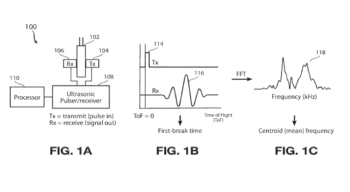
[0061] FIG. 1A shows an example apparatus 100 for analyzing a battery cell 102
using acoustic
signals according to this disclosure. The apparatus may include one or more
transmitting
(Tx) transducers 104 or other means for sending sound signals into the battery
cell (e.g.,
for transmitting a pulse or pulses of ultrasonic or other acoustic waves or
vibrations
through the battery cell). The apparatus further includes one or more
receiving (Rx)
transducers 106 or other means for receiving/sensing the sound signals, which
can receive
CA 03138173 2021-10-26
WO 2020/191396
PCT/US2020/024190
14
response signals generated from sound signals transmitted by the Tx
transducers 104. The
transmitted signals from a Tx transducer 104, from the side of the battery
cell 102 on
which the Tx transducer 104 is located may be referred to as pulse signals and
reflected
signals, e.g., from another side of the battery cell 102 may be referred to as
echo signals.
It is understood that references to response signals may include both the
pulse and the
echo signals. Further, one or more of the Tx transducers 104 may also be
configured to
receive response signals, and similarly, one or more of the Rx transducers 106
may also
be configured to transmit acoustic signals. Therefore, even though separately
illustrated
as Tx and Rx, the functionalities of these transducers may be for both sending
and
receiving acoustic signals. In some examples, one or more of the Tx
transducers 104 and
one or more of the Rx transducers 106 may be situated on the same side, or
oriented in a
manner such that the pulse signals transmitted from a Tx transducer 104 may be
received
by an Rx transducer 106, where the pulse acoustic signals do not necessarily
travel in a
straight line to be received by the Rx transducer 106. Transmitting and
receiving acoustic
signals in such orientations may also be referred to as pitch-catch, and the
apparatus 100
can also be configured to support the pitch-catch orientation in some
examples.
[0062] The ultrasonic pulser/receiver 108 shown in FIG. 1A coupled to the Tx
and Rx
transducers 104, 106 may include a controller (not separately illustrated) for
adjusting the
amplitude, frequency, and/or other signal features of the transmitted signals.
The
ultrasonic pulser/receiver 108 may also receive the signals from the Rx
transducers 106.
The processor 110 in communication with the ultrasonic pulser/receiver 108 may
be
configured to store and analyze the response signal waveforms according to
this
disclosure.
[0063] Although not explicitly shown in FIG. 1A, more than one Tx transducer
and/or more than
one Rx transducer can be placed in one or more spatial locations across the
battery cell.
This allows studying a spatial variation of acoustic signal features across
the battery cell
102. For instance, by placing two or more of the Tx transducers 104 at two or
more
locations across the battery cell 102, acoustic signals may be transmitted at
two or more
locations on the battery cell 102. Two or more of the Rx transducers 106 may
be placed
at two or more locations across the battery cell 102 to collect response
signals based on
the acoustic signals transmitted from one or more of the Tx transducers 104.
By using the
same arrangement of the one or more Tx transducers 104 and the one or more Rx
transducers 106 to study acoustic signal features across different battery
cells, e.g., a test
CA 03138173 2021-10-26
WO 2020/191396
PCT/US2020/024190
battery cell and a reference battery cell, a respective test data set
comprising the acoustic
signal features of the test battery cell and a reference data set comprising
the acoustic
signal features of the reference battery cell may be collected. Appropriate
comparisons
may be made between the test data set and the reference data set to correlate
any variations
between the two data sets to physical properties of the battery cells.
[0064] In some examples, the test battery cell and the reference battery cell
may be the same
battery cell at different stages of production. For instance, the reference
battery cell may
have a certain level of electrolyte fill, while the test battery cell may have
a greater or
lower level of electrolyte fill. In some examples, the reference battery cell
may be at a
certain production stage, while the test battery cell may be at an earlier or
later production
stage.
[0065] Furthermore, the placement and type of the Tx and/or Rx transducers
104, 106 used can
be customized based on the type of analysis, size, shape, and geometry of the
battery cell
102, and/or any other factor. In some examples, the Tx and/or Rx transducers
104, 106
can be single element transducers distributed in any regular linear or two-
dimensional
shape. In some examples, the Tx and/or Rx transducers 104, 106 can be single
element
transducers distributed in an array. In some examples, the Tx and/or Rx
transducers 104,
106 can be multi-element arrays distributed in a linear array or a two-
dimensional matrix.
In some examples, the Tx and/or Rx transducers 104, 106 can be phased array
transducers.
In the various above-described examples, the Tx and/or Rx transducers 104, 106
may be
placed by any suitable means (e.g., actuators, mechanical arms, screws,
adhesives, etc.)
to be in contact with a surface of the battery cell 102. Alternatively, the Tx
and/or Rx
transducers 104, 106 may be placed in proximity to the battery cell 102 in a
manner which
allows them to send and/or receive the acoustic signals into/from the battery
cell 102,
respectively.
[0066] FIG. 1B shows an example of an acoustic signal which may be transmitted
by a Tx
transducer 104. The Tx signal 114 is shown as a single pulse according to one
example
wherein the Tx transducer 104 transmits the acoustic pulse (e.g., an
ultrasonic pulse) into
the battery cell 102. The Rx signal 116 is the response signal generated by
the
transmission of the Tx signal 114, shown in this example to be a sinusoidal
wave. The Rx
signal 116 may be received by one or more of the Rx transducers 106.
[0067] In some examples, one or more features of the Tx signal 114 and/or the
Rx signal 116
may be studied. These features may be in the time domain and/or the frequency
domain.
CA 03138173 2021-10-26
WO 2020/191396
PCT/US2020/024190
16
For example, a time-of-flight (ToF) of a signal, which refers to the time
taken for a signal
or portion thereof to travel through the battery cell 102 or a portion
thereof. For example,
the ToF of the Tx signal 114 refers to the time lapsed from the time instance
(ToF = 0) at
which the Tx signal 114 was transmitted into the battery cell 102, and the
time instance
for any portion of the Rx signal 116 to be received by an Rx transducer 106.
The first
break time is another signal feature corresponding to the break time of the
first harmonic
of the response Rx signal 116. Similarly, a first peak of the Rx signal 116
may be another
signal feature. The amplitude of the Tx signal 114 and/or the amplitude of the
Rx signal
116 may constitute other signal features which may be studied.
[0068] FIG. 1C shows a frequency domain waveform 118, which may be obtained by
performing
a transformation such as a fast Fourier transform (FFT) on the time domain Rx
signal 116.
The waveform 118 provides an indication of the distribution of the frequencies
contained
in the Rx signal 116. The frequencies in the Rx signal 116 may have a range,
from
relatively low to relatively high frequencies. Statistical analysis of the
waveform 118 can
reveal the distribution of the frequency content. For example, signal features
such as a
centroid (or mean) frequency, frequency standard deviation, etc., may be
derived from
the waveform 118. These signal features may provide an indication of the
distribution of
the frequency content in the Rx signal 116. For example, if the Rx signal 116
contains a
large amount of low frequencies, then the centroid frequency obtained from the
waveform
118 may be relatively low. Conversely, if the frequency content of the Rx
signal 116 is
biased towards higher frequencies, then the centroid frequency obtained from
the
waveform 118 may be relatively high.
[0069] As previously explained, liquids may attenuate higher frequencies of an
acoustic Tx
signal 114 passing through, which means that the resultant Rx signal 116 may
have more
low frequency content for response signals obtained from areas of the battery
cell 102
which have liquid content. Thus, the centroid frequency obtained from the
waveform 118
for the liquid portions will be relatively low. Conversely, porous solids may
transmit the
higher frequencies of the acoustic Tx signal 114 passing through, which means
that the
resultant Rx signal 116 may have more high frequency content for response
signals
obtained from porous areas of the battery cell 102 which are saturated with
liquid
electrolyte. Thus, the centroid frequency obtained from the waveform 118 for
the porous
solid portions will be relatively high. In some example aspects, a spatial
distribution of
the centroid frequencies for signals obtained from various locations of a
battery cell may
CA 03138173 2021-10-26
WO 2020/191396
PCT/US2020/024190
17
be obtained, based on which, inferences may be made as to the composition
(liquid, solid,
level of saturation, etc.) of the regions of the battery cell 102 through
which the acoustic
signals may have traveled.
[0070] FIG. 2A shows an example composition of a battery cell 202. For the
purposes of
illustration of example aspects, the battery cell 202 may be a pouch battery
cell, with one
or more Tx transducers configured to transmit acoustic signals into the
battery cell 202
and one or more Rx transducers configured to receive response signals. In some
examples,
one or more transducers can be used to cause acoustic signals to travel
through at least
one or more portions of the battery cell 202, including one or more of
acoustic signals
(e.g., pulses) transmitted into the battery cell 202 and reflections (or
echos) of the acoustic
signals transmitted into the battery cell 202. The responses to the acoustic
signals can
include responses to the acoustic transmitted into the battery cell 202, or
responses to the
reflections of the acoustic signals transmitted into the battery cell 202.
[0071] In the example shown, the sensors 206 may be Rx transducers placed in a
2D array across
at least the illustrated surface of the battery cell 202. While not
specifically shown in this
view, Tx transducers may also be placed on the same surface (for the sensors
206 to sense
reflected or echo signals, for example), or a different surface (e.g.,
opposite surface, for
the sensors to sense transmitted signals). In some cases, one or more of the
sensors 206
may also include the functionality for transmitting the acoustic signals into
the battery
cell 202, as well as sensing the response signals. In some examples, the
transmitted and
reflected signals may be studied separately, while in some examples, a
combination of
transmission and reflection mode measurements can be used. For example, a
combination
of transmission and reflection mode measurements can be used to determine the
location
of a void. For example, the void can be in relation to the area of the battery
cell or in
relation to a thickness of the battery cell (e.g., between certain layers).
[0072] As shown in FIG. 2A, the composition of the battery cell 202 may vary
across the battery
cell 202. For example, the schematic view shows that an outer portion 204 may
be flooded
with liquid electrolyte and an inner portion 205 may contain a porous-solid
section filled
with or saturated with liquid electrolyte. As one of ordinary skill will
understand, the
variation in the composition of the battery cell 202 across its body may be
more complex
and may be less or more homogenous than the depicted example. By studying
responses
to acoustic signals transmitted through the battery cell 202 (or portions
thereof) and
CA 03138173 2021-10-26
WO 2020/191396
PCT/US2020/024190
18
extracting acoustic signal features from the responses, it is possible to
obtain information
about the composition of the battery cell 202.
[0073] FIG. 2B shows an example view of a spatial distribution 200 of acoustic
features of the
battery cell 202 of FIG. 2A, for example. In the depicted example, the
acoustic features
comprising centroid frequencies of the response signals collected from
sensors, such as
the sensors 206 is mapped. In more detail, the sensors 206 may collect
response signals
(e.g., as shown in FIG. 1B) which are responsive to the acoustic signals
transmitted into
the battery cell 202. A transformation such as an FFT on the response signals
may provide
the frequency responses (e.g., as shown in FIG. 1C) for the response signals,
from which
the acoustic features such as centroid frequency may be derived.
[0074] Although the sensors 206 are shown at specific locations on the surface
of the battery cell
202, these sensors may be moved or additional sensors may be utilized to
collect the
acoustic features at numerous locations on the surface of the battery cell
202. In some
cases, the acoustic features for certain locations may also be interpolated
based on the
acoustic features obtained from sensors in other locations (e.g., neighboring
locations). A
"spatially resolved map" may be created with the acoustic features plotted to
cover
numerous locations across one or more surfaces (e.g., the entire surface or
portions
thereof) of the battery cell 202. Various visualization schemes may be
employed for
observing the distribution of the acoustic features across the one or more
surfaces of the
battery cell 202.
[0075] In FIG. 2B, the spatial distribution 200 is depicted with different
schemes or shadings in
grayscale to correspond to different centroid frequencies. As seen from the
scale 210, the
centroid frequencies for the response signals may be in a range from low (214)
to high
(215) centroid frequencies. The areas marked with corresponding reference
numerals on
the spatial distribution 200 depict corresponding low centroid frequency area
214
(illustrated with crosshatches) and high centroid frequency area 215
(illustrated with dots)
according to the example shown.
[0076] In some examples, the visualization schemes provide a means for
determining the
underlying composition of the battery cell 202 in a non-destructive manner.
For instance,
in the low centroid frequency area 214, the composition of the battery cell
202 may be
estimated to contain portions filled predominantly with liquid electrolyte,
such as the
portion 204 shown in FIG. 2A. Similarly, in the high centroid frequency area
215, the
CA 03138173 2021-10-26
WO 2020/191396
PCT/US2020/024190
19
composition of the battery cell 202 may be estimated to contain porous solid
electrodes
filled with liquid electrolyte, such as the portion 205 shown in FIG. 2A.
[0077] FIGS. 3A-B illustrate examples of using spatially resolved maps, such
as those shown in
FIG. 2B, at different process steps and/or different levels of electrolyte
fill. In some
examples, FIGS. 3A-B provide techniques for inspection, monitoring,
visualizing, and/or
tracking the progression of electrolyte wetting during the fill and soaking
steps, as well
as during the formation and post-formation steps of a battery cell.
[0078] FIG. 3A illustrates a setup 300 with at least a portion of a battery
cell 302 (e.g., a pouch
cell) depicted for inspection. Sensors 306 (numbered 1-12) are placed across
the portion
of the battery cell 302 for monitoring. Acoustic measurements can be obtained
using the
sensors 306 when the battery cell 302 is a dry cell, prior to electrolyte
being injected.
Subsequently, liquid electrolyte may be injected into the battery cell 302,
and at any time
instance, a spatial distribution of the acoustic features of the battery cell
302 may be
derived. The spatial distribution can be mapped to the time instances, e.g.,
with an initial
time corresponding to the dry cell prior to liquid electrolyte injection, and
subsequent
time instances following the electrolyte injection. For example, the centroid
frequency
may be plotted across the battery cell 302 as described with reference to
FIGS. 2A-B
above. Once again, variations in the centroid frequency may be depicted with
different
visualization schemes, such as colors, shadings, etc. Based on the centroid
frequency at a
particular location, the underlying composition of the battery cell 302
corresponding to
that location may be estimated. From the spatial distribution of the centroid
frequency,
portions of the battery cell with relatively high and relatively low electrode
distribution
may be identified.
[0079] For example, sound or acoustic signals do not effectively travel
through gas or vacuum,
when compared to the acoustic signal transmission through liquids or solids.
Thus, a
porous solid portion filled with the liquid electrolyte may transmit high
frequency
acoustic signals, resulting in the high centroid frequency area 315
(illustrated with dots).
The portions of the battery cell 302 which have void spaces (e.g., pockets of
gas or
vacuum) may not transmit the acoustic signals effectively. Thus, in FIG. 3A,
the dry or
"unwetted" portions of the battery cell 302 may have lower centroid
frequencies, as
shown in the low centroid frequency area 314 (illustrated with crosshatches).
[0080] FIG. 3B shows a matrix 350 of spatial maps for one or more battery
cells. Each row of
the matrix 350 corresponds to a particular electrolyte fill level for a
battery cell.
CA 03138173 2021-10-26
WO 2020/191396
PCT/US2020/024190
Illustration schemes similar to those described with reference to FIG. 3A have
been
employed for the elements shown in the matrix 350. Each of these elements
illustrate a
spatial distribution of acoustic features, which may indicate high frequency
areas with
good electrolyte distribution and low frequency areas with poorer electrolyte
distribution
(e.g., dry or unwetted areas).
[0081] More specifically, the spatial distributions of acoustic features (or
spatial maps) for
battery cells with 70%-110% fill levels have been shown in the rows 352-360,
respectively, of matrix 350 in one illustrative example. For each of these
rows, the
columns 372-380 contain spatial maps at different process steps. The process
steps may
indicate soaking or wetting time (time after injection) of liquid electrolyte
within the
battery cell. For example, considering a battery cell with 70% electrolyte
fill in row 352
of the matrix 350, the spatial map of the battery cell at 0, 2, 4, 12, and 24
hours of wetting
time have been shown in the corresponding columns 372-380. Similar rows 354-
360 have
been shown for battery cells in successive rows above the bottom row, with
80%, 90%,
100% and 110%, respectively, at 0, 2, 4, 12, and 24 hours of wetting times at
columns
372-380.
[0082] From the matrix 350, the battery cell composition may be obtained for a
particular battery
cell at a wetting time of interest. For example, by studying the acoustic
features of the
battery cell with 70% electrolyte fill in row 352 at the different soaking
times in columns
372-380, the changes in the underlying composition of the battery cell at the
different
soaking times may be visualized. Based on the distribution of the centroid
frequencies
across the battery cell's surface area, the distribution of the electrolyte at
the various
soaking times may be estimated. Any white spaces or voids in the spatial maps
may
indicate corresponding dry or unwetted portions. From the matrix 350, ideal
soaking times
can be estimated.
[0083] For example, for the battery cell with 110% electrolyte fill in row
360, the illustration of
the spatial map between 2 hours and 4 hours at columns 374 and 376,
respectively, does
not reveal a significant difference, which may be taken as an indication that
the electrolyte
distribution does not vary significantly from 2 to 4 hours of soaking time.
Accordingly, a
soaking time of 4 hours or less may be considered to be sufficient for this
battery cell. In
another example, considering the battery cell with 70% electrolyte fill in row
352, dry
spots may be detected even after 24 hours of soaking time in column 380, and a
decision
may be made accordingly to allow longer soaking times for the battery cell's
finishing
CA 03138173 2021-10-26
WO 2020/191396
PCT/US2020/024190
21
steps to be completed. As will be appreciated, these examples are merely for
the sake of
explanation and the specific distribution and soaking times discussed in such
examples
are not to be construed as any inherent limitations to the disclosed aspects.
[0084] In some examples, the matrix 350 may provide analytical tools for
battery manufacturers
to determine the degree of uniformity or homogeneity of liquid electrolyte
within a battery
cell at various stages of development, from product and process design, to
prototyping
and process development environments, to pilot or volume production lines. In
some
examples, the acoustic signal analyses to obtain the matrix 350 may be
conducted using
continuous in-line measurements or monitoring, or with one or more periodic
snapshots
during the electrolyte fill and soaking process, using the sensors 306, for
example. The
analysis may be performed by the use of one or more computers and/or using any
suitable
combination of hardware and software.
[0085] In some examples, an aggregate or reduced-dimension acoustic metric or
acoustic score
may be derived from the 2D spatial distributions of acoustic features. For
example,
dimensionality reduction techniques may be applied to the 2D spatial
distributions 200 of
FIG. 2B, the matrix 350 of FIG. 3B, etc., to obtain a reduced dimension
metric, e.g., a
single dimension value referred to as a score. The score may be used in
addition to or as
an alternative to the 2D spatial distribution for determining electrolyte
distribution,
soaking time, etc.
[0086] FIG. 4A illustrates a graph 400 containing reduced dimension scores. In
the example
shown, the range of centroid frequency values, e.g., on the scale 210 of FIG.
2B or across
the various elements of the matrix 350 in FIG. 3B is reduced or converted to a
number
referred to as an "inhomogeneity index." The inhomogeneity index may be
calculated as
a function of distribution of the acoustic features such as the centroid
frequency. The
function may be based on the centroid frequencies considered individually or
in
combination across all locations on the battery cell 202/302 which are
monitored using
the sensors 206/306, for example.
[0087] In some implementations, a homogeneity index or acoustic score can be
used as an
alternative to the inhomogeneity index. The homogeneity index can include a
measure of
uniformity of distribution of electrolyte across the battery cell. In some
examples, the
homogeneity index or acoustic score can be standardized as a metric across
battery
chemistries and sizes.
CA 03138173 2021-10-26
WO 2020/191396
PCT/US2020/024190
22
[0088] In the graph 400 of FIG. 4A, the inhomogeneity index is shown on the
vertical axis (y-
axis). The function used to determine the inhomogeneity index may be, for
example, a
standard deviation (std.) or interquartile range (iqr.) of the distribution of
acoustic features
such as the centroid frequency. In the illustrated example, the centroid
frequencies may
be measured at the 12 locations of the sensors 206/306 placed across the
surface of the
battery cell 202/302, for example. The measurements of the acoustic features
may be
taken at the different soaking times shown in the matrix 350, in some
examples. In some
examples, the measurements of the acoustic features may be made at certain
manufacturing steps, and averaged across battery cells at various electrolyte
fill levels.
For example, at a certain soaking time corresponding to a column of the matrix
350 or a
certain manufacturing step, the acoustic features for the battery cells of the
various
electrolyte fill levels (rows of the matrix 350) may be measured. In an
example, the
acoustic features measured may be averaged across multiple battery cells
(e.g., 8 battery
cells) at each electrolyte fill level shown. The inhomogeneity index is
plotted for five
battery cells 402-410, each having a different electrolyte fill level as
shown.
Correspondingly, five plots 402-410 are shown, illustrating the variation in
the
inhomogeneity index over soaking times.
[0089] In the graph 400, a time scale is depicted in the horizontal axis (x-
axis). The different
times shown in the graph 400 may correspond to different stages of battery
cell finishing
during manufacture. In the example shown, a first stage corresponds to an
electrolyte fill
stage wherein electrolyte is filled into the battery cell. In some
implementations,
electrolyte injection into the battery cell may be preceded by pulling vacuum
on the cell.
In some examples, a fill stage can have multiple such electrolyte injection
and vacuum
steps. The electrolyte fill stage may correspond to the "Ohr" shown on the x-
axis. The
acoustic features are shown for the electrolyte fill stage on the y-axis in
the form of the
inhomogeneity index in plots 402-410.
[0090] A second stage corresponds to an electrolyte soaking stage wherein the
electrolyte is
allowed to distribute and soak the battery cell layers. The electrolyte
soaking stage may
span from "Ohr" to "24hr" on the x-axis, also referred to as soaking times.
The acoustic
features for the electrolyte soaking stage are shown on the y-axis in the form
of the
inhomogeneity index in plots 402-410.
[0091] A third stage corresponds to battery cell formation, wherein the
battery cells are cycled at
low rates for solid electrolyte interphase (SEI) layer formation. The battery
cell formation
CA 03138173 2021-10-26
WO 2020/191396
PCT/US2020/024190
23
stage is indicated as "formed" on the x-axis. During the formation stage,
e.g., for Lithium
Ion battery cells, gas is generated as the solvents or electrolyte breakdown.
With gas
generation, the mean value of the acoustic feature (such as centroid frequency
or rms
amplitude) drops, as does the Inhomogeneity Index. The acoustic features for
the battery
cell formation stage are also shown on the y-axis in the form of the
inhomogeneity index
in plots 402-410.
[0092] A fourth stage corresponds to a degassing and resealing stage (which
may be applicable
specifically for pouch cells). In this stage, the gas formed during the
formation stage is
removed and the battery cell is resealed. For degassing, a vacuum pulling
process may be
used to remove excess gas generated in the formation stage. Following the
degassing,
resealing is performed, e.g., for the pouch cells. The degassing and resealing
stage is
indicated as "reseal" on the x-axis. The electrolyte tends to redistribute
itself during
degassing and resealing, and correspondingly, the inhomogeneity index is seen
to rise
slightly, at the "reseal" time point on the x-axis.
[0093] For each inhomogeneity index plot 402-410, error bars are shown at the
different soaking
times. For example, error bars 402a-f have been specifically identified for
the
inhomogeneity index plot 402. Similar error bars are shown for the other plots
404-410
even if not specifically identified with reference numerals. These error bars
reflect the
maximum and minimum values for the inhomogeneity index obtained from acoustic
features for the battery cells in the group (e.g., the 8 battery cells
mentioned above) which
were averaged to obtain the inhomogeneity index of the plot 402 at each
soaking time.
The error bars provide useful information about the possible variations or
deviation from
the average inhomogeneity index at each soaking time.
[0094] The inhomogeneity index can be similarly calculated for other acoustic
features (e.g. rms
amplitude, first-break time, first peak, frequency standard deviation, etc.).
In some
examples, the inhomogeneity index can be a function of other aspects (other
than the std.
and iqr. noted above) of the distribution of acoustic features across
different locations of
the battery cell.
[0095] In general, the higher a battery cell's inhomogeneity index, the less
homogenous the
battery cell is. For example, in the case of electrolyte distribution a low
inhomogeneity
index may mean that the battery cell is more homogenous, reflecting a uniform
distribution of the electrolyte in the battery cell. Thus, at the start of an
electrolyte fill
process, during the electrolyte fill stage, the inhomogeneity index may be
high, and as
CA 03138173 2021-10-26
WO 2020/191396
PCT/US2020/024190
24
soaking time increases during the soaking stage, the inhomogeneity index
decreases.
When the battery cell is formed, the inhomogeneity index is seen to dip as
noted above,
while during the subsequent resealing and degassing stage, the inhomogeneity
index may
rise.
[0096] In some examples, a threshold value may be provided to determine when
the battery cell's
inhomogeneity index has reached a sufficiently low value. The threshold value
may be
used for analyzing the battery cell during the electrolyte soaking stage in
some examples.
In some examples, separate/different threshold values may be used for
subsequent
formation, degassing, and reseal stages.
[0097] For example, FIG. 4A illustrates a threshold bar 420, which represents
a threshold value
for the soaking stage. During the soaking stage, if the inhomogeneity index in
plots 402-
410 falls below the threshold bar 420, the respective battery cell is
considered to be
uniformly wetted by electrolyte. The threshold value can be estimated for
battery cells
based on when the score asymptotes to a stable value, or can be determined
based on a
reference dataset (comprising previously collected spatially resolved acoustic
signals and
derived features and metrics of similar battery cells).
[0098] FIG. 4B illustrates a table 450 containing example inferences for ideal
wetting times or
soaking times for different battery cells using the graph 400. These
inferences may be
similar to the inferences drawn from the matrix 350, as discussed above, but
based on a
different visualization scheme (i.e., the reduced dimension inhomogeneity
index in the
graph 400 vs. the 2D spatial maps of the matrix 350). For example, from the
graph 400,
the inhomogeneity index plot 402 for the battery cells with 70% electrolyte
fill is seen to
display variation beyond 24 hours of soaking time, which may lead to the
inference that
more than 24 hours of soaking time may be needed for battery cells with 70%
electrolyte
fill. In another example, from the graph 400, the inhomogeneity index plot 410
for the
battery cells with 110% electrolyte fill is seen to display minimal variation
between 2 and
4 hours of soaking time, which may lead to the inference that less than 4
hours of soaking
time may be sufficient for battery cells with 110% electrolyte fill. As will
be appreciated,
these conclusions are similar to those drawn from the matrix 350 for similar
battery cells.
Therefore, any visualization scheme or combination thereof may be used for
inferring or
estimating process steps such as soaking times for battery cells.
[0099] In some examples, the information from the matrix 350 and/or the graph
400/table 450
may be useful for process developers, e.g., to quickly and efficiently
optimize soaking
CA 03138173 2021-10-26
WO 2020/191396
PCT/US2020/024190
time for each type of battery cell (e.g., battery cells with different
electrolyte fills, shapes,
geometry, chemistry, electrochemical properties, etc.). This information can
also help
production engineers, for example, to inspect the wetting completion of each
battery cell
in-line, improve the average throughput of the soaking step, and more easily
identify and
address process drifts, if any.
i001001From the above information, process conditions that utilize
insufficient amounts of
electrolyte may be identified in some examples. Insufficient electrolyte
amounts may
affect all downstream process steps, and as such it is important to identify
these types of
defects or quality deviations as early in the battery cell production process
as possible.
Additionally, identification of such defects provides a pathway for building
statistical
models that correlate the distribution of acoustic properties across the
battery cell with
ultimate performance characteristics.
i001011In some examples, the acoustic feature information from the 2D maps of
the matrix 350
and/or the reduced-dimension scores from the graph 400/table 450 can also be
used for
making decisions that inform follow-on actions during process development
(e.g.,
adjustments to process parameters, soaking process, etc.) or during production
(e.g.
battery cell-specific soaking time, predictive maintenance, etc.)".
i001021Using the acoustic feature information as above for inspection and
analysis of a battery
cell can also inform the optimization of solid electrolyte interphase (SEI)
formation
protocols during process development and to assess the quality of the SEI
layer during
high-volume production. As previously described, the SEI layer formation
occurs when
the battery cells are cycled (charged and discharged) at low rates. The
uniform distribution
of SEI layers across the electrode active area is very important for ensuring
ideal or
optimal battery cell performance. But the SEI layer uniform distribution is
highly
dependent on the uniformity of electrolyte wetting. Hence, when inhomogeneity
index of
the battery cell is high at the end of soaking stage ¨ indicating non-uniform
wetting ¨ the
SEI layer formation is non-uniform. Thus, a patchy SEI layer (i.e., a low
quality SEI
layer) will have higher inhomogeneity index at the "formed" time point in FIG.
4A.
i001031The acoustic feature information (e.g., from the 2D maps of the matrix
350 and/or the
reduced-dimension scores from the graph 400/table 450) can also be used to
eliminate or
reduce the need for extensive battery cell aging, where the decay in each
battery cell's
open circuit voltage is monitored over time (i.e., a self-discharge rate of
the battery cell).
CA 03138173 2021-10-26
WO 2020/191396
PCT/US2020/024190
26
11001041 FIG. 5 illustrates a graph 500 according to an example electrolyte
fill process. The graph
500 can assist in development and optimization of electrolyte fill processes
for one or
more battery cells. The graph 500 can be obtained by studying acoustic
response
characteristics for a plurality of battery cells (e.g., pouch cells) subjected
to one or more
fill and vacuum cycles. The fill and vacuum cycles refer to filling of the
pouch cells with
electrolyte and subsequent sealing under vacuum conditions. The fill and
vacuum cycles
can lead to repeatable quality and allow for safe opening of gas bubbles
created during
formation. For example, a plurality of identical dry pouch cells may be filled
with the
same amount of electrolyte, and subjected to multiple fill and vacuum cycles,
with their
acoustic response characteristics studied using the aforementioned techniques
over a
course of their wetting times.
110010511n the graph 500, processes related to two (2x) fill/vacuum cycles and
three (3x)
fill/vacuum cycles are illustrated. An acoustic "wetting score" 502 on the y-
axis provides
a measure of the time-to-uniform-wetting of electrolyte, with a wetting time
506
identified in hours for electrolyte wetting time on the x-axis. The time-to-
uniform wetting
refers to the time taken for the wetting score to flatten out or reach an
asymptote. For
example, the wetting score 502a shows a plot of the time-to-uniform wetting
for pouch
cells subjected to the 2x fill/vacuum cycles, and the wetting score 502b shows
a plot of
the time-to-uniform wetting for the pouch cells subjected to 3x fill/vacuum
cycles. As
seen the wetting score 502b is considerably shorter for the 3x fill/vacuum
cycles than the
wetting score 502a for the 2x fill/vacuum cycles. Thus, the graph 500 can
effectively
indicate that subjecting the pouch cells to 3x fill/vacuum is likely to
improve electrolyte
wetting time and efficiency.
i001061Also identified in the graph 500 is AC impedance (ACR) 504. The ACR 504
can be
obtained by spectroscopy or studying acoustic responses to measure the
resistance and
capacitance properties of a battery, e.g., based on applying acoustic pulses
such as
sinusoidal AC excitation signals. The ACR 504a indicates a graph of the ACR
studied
over the course of the wetting time 506 for the battery cells subjected to the
2x fill/vacuum
cycle and the ACR 504b indicates a graph of the ACR studied over the course of
the
wetting time 506 for the battery cells subjected to the 2x fill/vacuum cycle.
In the
illustrated example, studying the ACR 504a and ACR 504b is not seen to provide
sufficient information to identify ideal wetting times for the battery cells
subjected to the
CA 03138173 2021-10-26
WO 2020/191396
PCT/US2020/024190
27
different fill/vacuum cycle process conditions. Thus, wetting score 502 is
seen to provide
a better indication of soaking times, in comparison to the ACR 504.
i001071FIG. 6 illustrates a graph 600 according to another example electrolyte
fill process. The
graph 600 can be used for development and optimization of electrolyte fill
processes for
one or more battery cells. The graph 600 can be obtained by studying acoustic
response
characteristics for a plurality of identical battery cells (e.g., pouch cells)
filled with the
same amount of electrolyte with an identical electrolyte fill process but with
differing
stack pressure amongst at least two of the plurality of the identical battery
cells. The stack
pressure refers to compressing of the pouch cells (e.g., between two pieces of
acrylic with
springs) during a period of soaking (e.g., 24 hours) and formation steps. For
example,
between two identical cells, stack pressure may be applied to one cell but not
the other in
obtaining the graph 600. The resulting difference in the two identical cells
can be seen in
the post-formation acoustic wetting scores 602 studied over a wetting time
606. For
example, a wetting score 602a is shown for the cell with the stacked pressure
(or stacked
cell) and a wetting score 602b is shown for the cell without the stacked
pressure (or
unstacked cell). The difference between the wetting scores 602a and 602b
illustrates
significant differences in formation capacities between the two cells as
illustrated.
i001081FIG. 6 also illustrates ACR 604 studied over the wetting time 606 for
the two cells. It is
seen that AC impedance ACR 604a for the stacked cell is not significantly
different from
the ACR 604b for the unstacked cell. Thus, stacked pressure can provide
another measure
for identifying process conditions which can lead to better wetting
scores/electrolyte
wetting time and efficiency.
i001091FIG. 7 illustrates plot 700 illustrating variations 720-728 in
manufacturing conditions
based on acoustic inspection on battery cells during various stages of
electrolyte wetting.
A first batch of battery cells 41-44 are identified as examples of battery
cells which are
coated and stacked identically during a first time-period under consideration
(e.g., on a
particular day). A second batch of battery cells 45 ¨48 are examples of
battery cells which
are assembled (e.g., into pouch packages) on a subsequent second time-period
(e.g., on a
following day). All battery cells 41-48 are subjected to acoustic testing
using the
aforementioned techniques during various stages of their manufacture, such as
during
soaking 702, formation 704, and after formation 706. The battery cells 45-48
of the
second batch which were assembled during the second time-period are observed
to have
minor defects attributed to poor storage in an illustrative example. The
difference between
CA 03138173 2021-10-26
WO 2020/191396
PCT/US2020/024190
28
the two batches of battery cells are identified using an acoustic wetting
score 720
(measured during soaking 702) and is correlated with the battery cells'
different lifetime
cycling performance (number of cycles to reach 70% initial capacity). By
contrast, these
differences are not easily observable by standard state-of-the-art electrical
methods like
formation capacity 722, DC resistance 724, self-discharge rate 726, or cycle
life 728.
Accordingly, measuring acoustic wetting scores 720 using the above techniques
during
soaking is seen to provide discernible and actionable insights which are not
available
using the other methods 722-728.
100110] Furthermore, measuring the quality of battery cells using acoustic
signals during soaking
can provide the following advantageous characteristics during battery cell
development
and production: faster optimization of process parameters during development;
and the
ability for screening and identifying cells that may have been discarded
during
commercial production due to poor quality, potentially providing opportunities
for
remedying corresponding defects during the manufacturing process.
[00111]Accordingly, it will be appreciated that example aspects include
various methods for
performing the processes, functions and/or algorithms disclosed herein. For
example,
FIG. 8 illustrates a process 800 for estimating various aspects of battery
cell quality,
soaking time, process development, etc., using acoustic features according to
aspects of
this disclosure. The process 800 can include determining acoustic features at
two or more
locations of the battery cell, the acoustic features based on one or more of
acoustic signals
travelling through at least one or more portions of the battery cell during
one or more
points in time or responses to the acoustic signals obtained during one or
more points in
time, wherein the one or more points in time correspond to one or more stages
of
electrolyte distribution in the battery cell. The acoustic signals travelling
through at least
one or more portions of the battery cell can include one or more of acoustic
signals
transmitted into the battery cell or reflections of the acoustic signals
transmitted into the
battery cell, while the responses to the acoustic signals can include one or
more of
responses to the acoustic signals transmitted into the battery cell or
responses to the
reflections of the acoustic signals transmitted into the battery cell.
1100112] For example, at the step 802 of the process 800 includes collecting
acoustic waveforms
(e.g., the Rx signal 116) at various locations. For example, the sensors
206/306 may be
used to collect the response signals at the one or more locations on at least
one surface of
the battery cell 202/302, over one or more points in time.
CA 03138173 2021-10-26
WO 2020/191396
PCT/US2020/024190
29
[00113] The step 804 includes extracting one or more acoustic signal features
from the acoustic
waveforms. For example, various algorithms (e.g., FFT, statistical functions,
etc.) may be
used to determine acoustic signal features in time domain, frequency domain,
or
combinations of time and frequency domains. In some examples, the acoustic
signal
features may include a centroid (mean) frequency, first break time, first
peak, amplitude,
standard deviation of frequency, etc., determined from the acoustic signal
waveforms
collected by the sensors.
11001141 In some examples, the process 800 includes determining acoustic
features at one or more
locations of the battery cell, the acoustic features based on one or more of
acoustic signals
travelling through at least one or more portions of the battery cell during
two or more
points in time or responses to the acoustic signals obtained during two or
more points in
time, wherein the two or more points in time correspond to one or more stages
of
electrolyte distribution in the battery cell, and determining one or more
characteristics of
the battery cell based on the acoustic features at the one or more locations
of the battery
cell. For example, by studying the acoustic features at a single point or
location over the
course of two or more points in time (e.g., the two dimensional maps for one
of the fill
levels 352-360, studied over two or more points in time 372-380 in FIG. 3B),
can be used
to determine characteristics of the battery cell as explained above.
11001151 In some examples, the process 800 includes determining acoustic
features at two or more
locations of the battery cell, the acoustic features based on one or more of
acoustic signals
travelling through at least one or more portions of the battery cell during
one or more
points in time or responses to the acoustic signals obtained during one or
more points in
time, wherein the one or more points in time correspond to one or more stages
of
electrolyte distribution in the battery cell; and determining one or more
characteristics of
the battery cell based on the acoustic features at the two or more locations
of the battery
cell. For example, by studying the acoustic features at two or more locations
at one or
more points in time (e.g., studying two or more points on the two dimensional
maps for
at least one of the fill levels 352-360, over one or more points in time 372-
380 in FIG.
3B), can be used to determine characteristics of the battery cell as explained
above
11001161 In some examples, one or more of the following steps 806, 808, 810
may be performed
in any order to reach the step 812 of determining or estimating the one or
more
characteristics of a battery cell. For example, the step 812 of the process
800 may be
reached from the step 804 and/or from one or more of the following steps 806,
808, 810.
CA 03138173 2021-10-26
WO 2020/191396
PCT/US2020/024190
The specific process steps to be employed may be chosen based on specific
needs or goals
for the disclosed techniques. Accordingly, before proceeding to describe the
following
steps 806, 808, 810 in more detail, the step 812 will now be described.
[00117] The step 812 is directed to determining one or more characteristics of
the battery cell
based on the acoustic features at the two or more locations of the battery
cell. For example,
the step 812 includes estimating one or more characteristics of the battery
cell using the
information obtained from the acoustic features. The step 812 may further
include
performing actions such drawing conclusions about, making decisions about,
making any
modifications, etc., regarding the battery cell's process steps. These actions
may be
regarding the battery cell quality, process development, manufacturing,
soaking times,
etc. In the examples described above, determining soaking times for acceptable
electrolyte distribution was specifically considered, and accordingly,
determining the
soaking times can be one of the actions included in the step 812. Since the
step 812 may
be reached based on an understanding of the acoustic signal features derived
from the
various locations on the surface, in one example, the process 800 may proceed
from the
step 804 to the step 812.
[001181In some examples, the process 800 may proceed to the step 806 from the
step 804. The
step 806 includes creating a two-dimensional map based on the acoustic
features at the
two or more locations, wherein determining the one or more characteristics of
the battery
cell based on the acoustic features at the two or more locations of the
battery cell
comprises determining the one or more characteristics of the battery cell
based on the
two-dimensional map. For example, a 2D spatial map of the acoustic signal
features can
be generated, e.g., as shown in the spatial distribution 200 of FIG. 2B.
[00119] Some examples further include creating a matrix with two or more two-
dimensional maps
created using acoustic features obtained at two or more points in time from
one or more
battery cells at two or more electrolyte fill levels. For example, the spatial
maps may be
determined for various battery cells, e.g., at different fill levels. The
spatial maps may
also be generated at different soaking times. Thus, the spatial maps may be
organized in
the form of the matrix 350 in some examples.
11001201 In some examples, the process 800 may proceed to the step 808 from
the step 806. The
step 808 can include applying a dimension reduction algorithm to the acoustic
features
obtained at the two or more points in time. For example, the dimension
reduction
algorithm can be applied to the two-dimensional map to determine a reduced-
dimension
CA 03138173 2021-10-26
WO 2020/191396
PCT/US2020/024190
31
score. In some examples, example, the spatial distribution of a battery cell
may be
considered individually or in combination with spatial distributions of other
battery cells
to generate a dimension-reduced score. For example, the graph 400 with the
inhomogeneity index may be created for various battery cells under
consideration (e.g.,
for battery cells having different electrolyte fill levels). Various
dimensionality reduction
algorithms (e.g., principal component analysis (PCA), uniform manifold
approximation
and prediction (UMAP), non-negative matrix factorization (NMF)), etc.), may be
used in
the step 508 to obtain the dimension-reduced metric or score.
1100121] In the step 810, the process 800 can include plotting the reduced-
dimension score as a
function of soaking times for electrolyte distribution in the battery cell,
wherein the one
or more characteristics comprise ideal soaking times for the battery cell, and
the reduced-
dimension score comprises an inhomogeneity index or an electrolyte
distribution
homogeneity index. For example, the dimensionality reduced score may be
optionally
augmented with an error factor and then compared with a threshold (e.g., the
threshold
420). In some cases, such as for the soaking times, the comparison may reveal
inhomogeneity status. In some cases, comparisons with a reference battery
cell's score
may be used to determine potential deviations. The reference battery cell may
be a battery
cell of similar characteristics and type (e.g., same fill level as the battery
cell under test).
A reference database may contain scores for various reference battery cells.
The reference
database may be stored in a computer (e.g., the 110) in communication with the
test
apparatus 100 shown in FIG. 1A or in any other remote storage location (e.g.,
a cloud
storage).
1100122] The step 812 has been previously described. The one or more points in
times referred to
in the previous step can belong to one or more of process steps comprising
soaking,
formation, and self-discharge aging of the battery cell, or to one or more
charge/discharge
cycles of the battery cell. The estimations of the one or more characteristics
in the step
812 may be performed using any suitable algorithm that uses the 2D spatial
maps and/or
scores, and/or comparisons thereof discussed in the preceding steps.
1100123] In some examples, the one or more characteristics include one or more
of battery cell
quality, ideal soaking time, process drifts, or manufacturing defects. For
example, the
manufacturing defects can include one or more of contamination, dry spots,
voids,
electrode and separator folds or tears.
CA 03138173 2021-10-26
WO 2020/191396
PCT/US2020/024190
32
[00124] In some examples, the one or more characteristics can include battery
cell performance
corresponding to one or more of teardown analysis, formation capacity,
Electrochemical
Impedance Spectroscopy (EIS), self-discharge aging, or charge/discharge
cycling. For
example, the step 812 can further include determining one or more process
parameters
for electrolyte filling of the battery cell based on the one or more
characteristics, the one
or more process parameters comprising one or more of a number of fill/vacuum
cycles, a
fill amount of electrolyte per fill step, vacuum pressure, fill temperature,
or electrolyte
injection distribution for the battery cell.
[00125] In some examples, the one or more characteristics can include
determining one or more
pre-fill parameters for implementing upstream process and materials
optimization of the
battery cell based on the one or more characteristics, the one or more pre-
fill parameters
comprising one or more of an electrodes materials and composition ratio,
electrode
porosity, separator type, materials, porosity, and coatings; electrolyte
chemistry,
electrolyte composition, electrolyte viscosity, electrode additives or
electrolyte additives.
[00126] In some examples, the one or more characteristics can include
determining one or more
soaking parameters for a soaking process of the electrolyte in the battery
cell based on the
one or more characteristics, the one or more soaking parameters comprising one
or more
of soaking temperature, soaking time, stack pressure, voltage (e.g., bump,
charge, or hold)
during soaking, battery cell orientation, or agitation (e.g., press rolling or
vibration) of the
battery cell.
[00127] In some examples, the process 800 can include comparing the acoustic
features to a
reference set of acoustic features, the reference set of acoustic features
obtained at
corresponding two or more locations of a reference battery cell. In some
examples,
determining one or more characteristics of the battery cell can further be
based on
comparing the acoustic features to predetermined corresponding threshold
values.
[00128] Additionally, the estimations obtained in the step 812 can be used to
generate insights in
the step 814, as discussed further below. For example, one or more insights
can be based
on the determined one or more characteristics, the insights comprising hints
for one or
more of process design, process optimization, process monitoring, control, or
decisions
about downstream processes for manufacturing one or more battery cells.
[001291In the step 814, the insights may be generated using the
estimates/actions/decisions
obtained in the step 812. The insights that may be used as hints in guiding
the production
process of the battery cells. For example, in process development the
estimated
CA 03138173 2021-10-26
WO 2020/191396
PCT/US2020/024190
33
characteristics of a battery cell (e.g., ideal soaking time, etc.) obtained
from studying a
battery cell during a particular state or iteration of the battery cell
manufacturing process
can be used to generate corresponding insights such as the soaking time to be
used in
future iterations. The subsequent next iterations of process design can
utilize these
insights to potentially alter their soaking times, or otherwise modify their
cell design
processes by incorporating these insights. In some examples, the insights from
the step
814 can be used in monitoring a manufacturing line for drift in quality. In
some examples
of battery cell production, the insights can deliver real-time feedback into
process
controls, e.g. to tune parameters to adjust for any incipient deviations. In
some examples,
the insights can guide decisions on how a production process for cell should
proceed in
the downstream process steps (e.g., based on wetting scores, the length of
time a cell
should be soaked for, or how long to a cell which has been soaked should be
allowed to
age before proceeding to subsequent steps, etc.)
[00130] Those of skill in the art will appreciate that information and signals
may be represented
using any of a variety of different technologies and techniques. For example,
data,
instructions, commands, information, signals, bits, symbols, and chips that
may be
referenced throughout the above description may be represented by voltages,
currents,
electromagnetic waves, magnetic fields or particles, optical fields or
particles, or any
combination thereof.
110013111 Further, those of skill in the art will appreciate that the various
illustrative logical blocks,
modules, circuits, and algorithm steps described in connection with the
aspects disclosed
herein may be implemented as electronic hardware, computer software, or
combinations
of both. To clearly illustrate this interchangeability of hardware and
software, various
illustrative components, blocks, modules, circuits, and steps have been
described above
generally in terms of their functionality. Whether such functionality is
implemented as
hardware or software depends upon the particular application and design
constraints
imposed on the overall system. Skilled artisans may implement the described
functionality in varying ways for each particular application, but such
implementation
decisions should not be interpreted as causing a departure from the scope of
the present
invention.
[00132]Accordingly, an aspect of the invention can include a computer-readable
media
embodying a method of analyzing electrolyte fill distribution in a battery
cell.
CA 03138173 2021-10-26
WO 2020/191396
PCT/US2020/024190
34
Accordingly, the invention is not limited to illustrated examples and any
means for
performing the functionality described herein are included in aspects of the
invention.
[00133] While the foregoing disclosure shows illustrative aspects of the
invention, it should be
noted that various changes and modifications could be made herein without
departing
from the scope of the invention as defined by the appended claims. The
functions, steps
and/or actions of the method claims in accordance with the aspects of the
invention
described herein need not be performed in any particular order. Furthermore,
although
elements of the invention may be described or claimed in the singular, the
plural is
contemplated unless limitation to the singular is explicitly stated.
[00134] Illustrative examples of the disclosure include:
[00135] Example 1: A method of analyzing a battery cell, the method
comprising: determining
acoustic features at two or more locations of the battery cell, the acoustic
features based
on one or more of acoustic signals travelling through at least one or more
portions of the
battery cell during one or more points in time or responses to the acoustic
signals obtained
during one or more points in time, wherein the one or more points in time
correspond to
one or more stages of electrolyte distribution in the battery cell; and
determining one or
more characteristics of the battery cell based on the acoustic features at the
two or more
locations of the battery cell.
[00136] Example 2: The method of Example 1, further comprising creating a two-
dimensional
map based on the acoustic features at the two or more locations, wherein
determining the
one or more characteristics of the battery cell based on the acoustic features
at the two or
more locations of the battery cell comprises determining the one or more
characteristics
of the battery cell based on the two-dimensional map.
[00137] Example 3: The method of any of Examples 1 or 2, further comprising
creating a
matrix with two or more two-dimensional maps created using acoustic features
obtained
at two or more points in time from one or more battery cells at two or more
electrolyte
fill levels.
[00138] Example 4: The method of any of Examples 1-3, further comprising
applying a
dimension reduction algorithm on the acoustic features to determine a reduced-
dimension
score.
i001391Example 5: The method of any of Examples 1-4, further comprising
plotting the
reduced-dimension score as a function of soaking times for electrolyte
distribution in the
battery cell, wherein the one or more characteristics comprise ideal soaking
times for the
CA 03138173 2021-10-26
WO 2020/191396
PCT/US2020/024190
battery cell, and the reduced-dimension score comprises an inhomogeneity index
or an
electrolyte distribution homogeneity index.
[00140] Example 6: The method of any of Examples 1-5, wherein the one or more
points in
times belong to one or more of process steps comprising soaking, formation,
and self-
discharge aging of the battery cell, or to one or more charge/discharge cycles
of the battery
cell.
i001411Example 7: The method of any of Examples 1-6, wherein the one or more
characteristics include one or more of battery cell quality, ideal soaking
time, process
drifts, or manufacturing defects.
[00142] Example 8: The method of any of Examples 1-7, wherein the
manufacturing defects
comprise one or more of contamination, dry spots, voids, electrode and
separator folds or
tears.
[00143] Example 9: The method of any of Examples 1-8, wherein the one or more
characteristics include battery cell performance corresponding to one or more
of teardown
analysis, formation capacity, Electrochemical Impedance Spectroscopy (EIS),
self-
discharge aging, or charge/discharge cycling.
[00144] Example 10: The method of any of Examples 1-9, further comprising
determining one or
more process parameters for electrolyte filling of the battery cell based on
the one or more
characteristics, the one or more process parameters comprising one or more of
a number
of fill/vacuum cycles, a fill amount of electrolyte per fill step, vacuum
pressure, fill
temperature, or electrolyte injection distribution for the battery cell.
[00145] Example 11: The method of any of Examples 1-10, further comprising
determining one
or more pre-fill parameters for implementing upstream process and materials
optimization of the battery cell based on the one or more characteristics, the
one or more
pre-fill parameters comprising one or more of an electrodes materials and
composition
ratio, electrode porosity, separator materials, electrolyte chemistry,
electrolyte
composition, electrolyte viscosity, electrode additives or electrolyte
additives.
[00146] Example 12: The method of any of Examples 1-11, further comprising
determining one
or more soaking parameters for a soaking process of the electrolyte in the
battery cell
based on the one or more characteristics, the one or more soaking parameters
comprising
one or more of soaking temperature, stack pressure, voltage during soaking,
battery cell
orientation, or agitation of the battery cell.
CA 03138173 2021-10-26
WO 2020/191396
PCT/US2020/024190
36
[00147]Example 13: The method of any of Examples 1-12, wherein the acoustic
features
comprise one or more of a time-of-flight, centroid (mean) frequency, first
break time, first
peak, amplitude, or standard deviation of frequency of the acoustic signals.
[00148]Example 14: The method of any of Examples 1-13, wherein the acoustic
signals
travelling through at least one or more portions of the battery cell comprise
one or more
of acoustic signals transmitted into the battery cell or reflections of the
acoustic signals
transmitted into the battery cell.
[00149]Example 15: The method of any of Examples 1-14, wherein the responses
to the
acoustic signals comprise one or more of responses to the acoustic signals
transmitted
into the battery cell or responses to the reflections of the acoustic signals
transmitted into
the battery cell.
[00150] Example 16: The method of any of Examples 1-15, wherein the acoustic
features are
determined from one or more time-domain characteristics, one or more frequency-
domain
characteristics, or one or more time-frequency domain characteristics of the
transmitted
acoustic signals or the response signals or combinations thereof.
[00151] Example 17: The method of any of Examples 1-16, further comprising
comparing the
acoustic features to a reference set of acoustic features, the reference set
of acoustic
features obtained at corresponding two or more locations of a reference
battery cell.
[00152] Example 18: The method of any of Examples 1-17, wherein determining
one or more
characteristics of the battery cell is further based on comparing the acoustic
features to
predetermined corresponding threshold values.
[00153]Example 19: The method of any of Examples 1-18, wherein the one or more
characteristics comprise a quality of a solid electrolyte interphase (SEI)
layer of the
battery cell.
[00154] Example 20: The method of any of Examples 1-19, further comprising
determining one
or more insights based on the determined one or more characteristics, the
insights
comprising hints for one or more of process design, process optimization,
process
monitoring, control, or decisions about downstream processes for manufacturing
one or
more battery cells.
[00155] Example 21. A non-transitory computer-readable medium having stored
thereon
computer-readable instructions that, upon being executed by one or more
processors,
cause the one or more processors to: determine acoustic features at two or
more locations
of the battery cell, the acoustic features based on one or more of acoustic
signals travelling
CA 03138173 2021-10-26
WO 2020/191396
PCT/US2020/024190
37
through at least one or more portions of the battery cell during one or more
points in time
or responses to the acoustic signals obtained during one or more points in
time, wherein
the one or more points in time correspond to one or more stages of electrolyte
distribution
in the battery cell; and determine one or more characteristics of the battery
cell based on
the acoustic features at the two or more locations of the battery cell.
i001561Example 22. A system comprising one or more processors; and memory
including
instructions that, upon being executed by the processor one or more
processors, cause the
system to: determine acoustic features at two or more locations of the battery
cell, the
acoustic features based on one or more of acoustic signals travelling through
at least one
or more portions of the battery cell during one or more points in time or
responses to the
acoustic signals obtained during one or more points in time, wherein the one
or more
points in time correspond to one or more stages of electrolyte distribution in
the battery
cell; and determine one or more characteristics of the battery cell based on
the acoustic
features at the two or more locations of the battery cell.
i001571Example 23: A method of analyzing a battery cell according to any of
the Examples 1-
22, the method comprising: determining acoustic features at one or more
locations of the
battery cell, the acoustic features based on one or more of acoustic signals
travelling
through at least one or more portions of the battery cell during two or more
points in time
or responses to the acoustic signals obtained during two or more points in
time, wherein
the two or more points in time correspond to one or more stages of electrolyte
distribution
in the battery cell; and determining one or more characteristics of the
battery cell based
on the acoustic features at the one or more locations of the battery cell.