Note: Descriptions are shown in the official language in which they were submitted.
CA 03138175 2021-10-26
WO 2020/220008 PCT/US2020/029996
1
SELF-FILLING, SELF-SEALING CONTAINER SYSTEM
CROSS-REFERENCE TO RELATED APPLICAIONS
[0001] This application claims the benefit of Provisional Application No.
62/839,504, filed
April 26, 2019, the disclosures of which are incorporated herein by reference.
TECHNICAL FIELD OF THE INVENTION
[0002] The present disclosure relates generally to containers, and more
specifically, to a
self-filling, self-sealing container system designed to capture and remove
materials from
places that are otherwise difficult to access with standard bailing
techniques.
BACKGROUND
[0003] Containers such as buckets and pails are known and often used for
scooping,
holding, and transporting various materials such as fluids, solids, or
combinations thereof.
Buckets are generally filled from the top, either by pouring material into the
bucket from
another container or by tipping and dipping the bucket into a material,
causing the material
to flow into or to be scooped into the bucket.
[0004] Removing material from a space or another container with a bucket
generally
requires either significant force to fully submerge the bucket while it
remains in an upright
position or a space large enough to allow the bucket to tip to the side.
[0005] Previous solutions have been proposed in patents directed toward
devices used
for bailing water and other related uses. U.S. Pat. Nos. 1,333,793 and
3,994,522 are
illustrative of buckets containing check valves or valve flaps fixed into the
bottom of the
CA 03138175 2021-10-26
WO 2020/220008 PCT/US2020/029996
2
bucket to allow water to pass into the bucket and be captured from below.
However, no
satisfactory solution has been developed to easily remove materials from a
space using
a container with a simple, durable, and scalable system that is cost-
effective, easy to
repair, and easy to transport.
BRIEF SUMMARY OF THE INVENTION
[0006] The present invention is directed to a self-filling, self-sealing
container system. The
container system includes a container element with an interior cavity. The
container
system also includes at least one hole or a series of holes through the
container element
to the interior cavity that are sized and arranged in pattern and number to
allow maximum
flow of a material into the container system while maintaining structural
integrity of the
system when it is placed into and removed from various materials.
[0007] At least one seal assembly is affixed to the container element. The
seal assembly
may be positioned anywhere on the container element. A seal assembly comprises
at
least one seal element capable of sealing at least one hole through the
container element.
Upon sufficient inward pressure exerted by materials located outside of the
container
system, at least one element of the seal assembly is displaced to an unsealed
position,
simultaneously allowing material to enter the interior cavity through at least
one hole
located on the container element. When materials are no longer entering the
interior
cavity, sufficient outward pressure of the materials within the interior
cavity causes the
seal assembly to return to a sealed position, closing at least one hole.
[0008] Additional features and advantages of the invention will be set forth
in the
description which follows, and in part will be obvious from the description,
or may be
learned by the practice of the invention. The invention is not limited in its
application to
the details of construction and to the arrangements of the components set
forth in the
following description or illustrated in the drawings.
BRIEF DESCRIPTION OF THE DRAWINGS
CA 03138175 2021-10-26
WO 2020/220008 PCT/US2020/029996
3
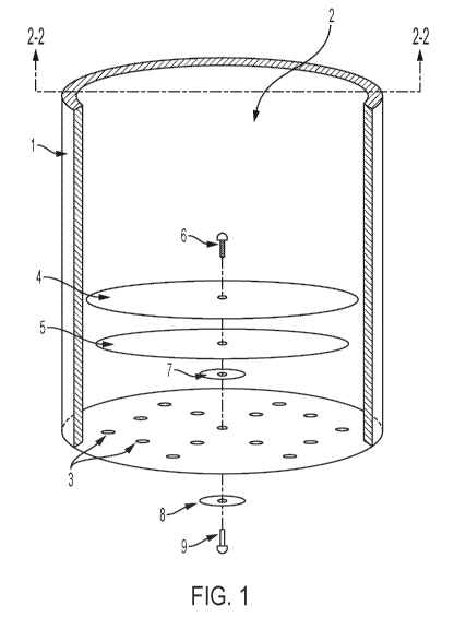
[0009] FIG. 1 is an upper-perspective, cutaway view of a self-filling, self-
sealing container
system according to one embodiment of the present invention.
[0010] FIG. 2 is a cross-sectional view of the container system of FIG. 1
taken along line
2-2 of FIG. 1.
[0011] FIG. 3 is a top view of the container system of FIG. 1.
[0012] FIG. 4 is a bottom view of the container system of FIG. 1.
[0013] FIG. 5 is a cross-sectional view of the container system of FIG. 1
taken along line
2-2 of FIG. 1 showing the container system placed in a material with material
entering
into the interior cavity of the container system and displacing elements of
the seal
assembly.
[0014] FIG. 6 is a cross-sectional view of the container system of FIG. 1
taken along line
2-2 of FIG. 1 showing the container system with captured material within the
interior cavity
of the container system after the container system has been removed from
uncaptured
material of FIG. 5 and the outward pressure of captured material returns the
seal
assembly to its sealed position.
DETAILED DESCRIPTION OF THE INVENTION
[0015] The present invention relates to a self-filling, self-sealing container
system that
may be used generally to easily remove material from a space without the
requirement of
a pump, siphon, or scoop. The container system of the present invention
contains at least
one seal assembly capable of closing at least one hole located anywhere on the
container
element. When the container system of the present invention is placed into a
material,
the material enters into the interior cavity of the container element through
the holes by
CA 03138175 2021-10-26
WO 2020/220008 PCT/US2020/029996
4
displacing at least one seal element of the seal assembly into an unsealed
position
through exertion of sufficient inward pressure against the seal assembly.
[0016] Once material has entered into the interior cavity of the container
element, the
container system may be removed from the material, and the resulting outward
pressure
of captured material returns the seal assembly to its sealed position, thereby
closing at
least one hole located in the container element to allow the captured material
to remain
within the interior cavity of the container element until poured out or
otherwise removed.
It should be noted that, although the container system may be operated without
the
requirement of a pump or siphon, it may be used in conjunction with either a
pump or
siphon or both. For example, a pump or siphon may be used to remove captured
material
from the container.
[0017] FIG. 1 illustrates one embodiment of the present invention comprising a
tubularly
shaped container element 1 with interior cavity 2. The container element 1 is
modified to
include a number of holes 3, arranged in size and pattern to allow maximum
flow of a fluid
or material through the holes 3 without compromising the structural integrity
of the
container element I. The seal assembly of the preferred embodiment of the
present
invention as illustrated in FIG. 1 comprises an upper seal element 4 and lower
seal
element 5. FIG. 4 illustrates a pattern of holes 3 suitable for one embodiment
of the
present invention. The holes 3 in the container element 1 are sized to keep
undesirable
particles from entering through the container element 1 into the interior
cavity 2 and
potentially blocking lower seal element 5 from closing over holes 3. In
another
embodiment, holes 3 can be located anywhere in the container element 1,
including in
such a way as to allow a specific amount or type of material to remain
uncaptured. Size
and placement of holes 3 may depend on the types, weights, and amounts of
material or
materials to be captured, the speed at which the material or materials are to
be captured,
the environmental conditions in which the materials will be captured, transfer
of captured
material, or extended storage of captured materials.
CA 03138175 2021-10-26
WO 2020/220008 PCT/US2020/029996
[0018] The container element of the preferred embodiment of the present
invention is
formed from a commercial or engineering-grade polymer. Other materials are
available
that would be suitable for use on their own or together with other materials
for the
container element in alternative embodiments of the present invention. The
types of
material used to form the container element of the present invention may
depend on the
types, weights, and amounts of material or materials to be captured, the
environmental
conditions in which the materials will be captured, transfer of captured
material, or
extended storage of captured materials. Examples of suitable materials are
metal, wood,
bamboo, ceramic, glass, polymers, or composite materials such as carbon fiber,
or
fiberglass, or any other similar materials. Those in the art will understand
that any suitable
material, now known or hereafter developed, may be used in forming the
container
element of the container system described herein.
[0019] The container element of the preferred embodiment of the present
invention as
illustrated in FIG. 6 is equipped with at least one handle 10 for lowering and
raising the
container system into and out of the material to be captured, and at least one
lid 12. In
another embodiment of the present invention, the container element may be made
of a
material with greater density or weight than the material in which it will be
placed so
that the system, with or without any type of handle, will sink into the
material without
application of downward force. In yet another embodiment of the present
invention,
one or more handles, grips, or cavities for hooking may be located on the
container system for additional manner of lifting and moving the container
element. In
yet another embodiment of the present invention, one or more lids or coverings
may be
permanently or removably affixed on the container to prevent objects from
entering the
interior cavity of the container element or to allow for pressurization and
depressurization of the interior cavity.
[0020] The preferred embodiment of the present invention includes molded
graduation
lines 11 as illustrated in FIG. 6 along any surface of the container system
for accurate
measuring so that a user may quickly identify the amount of material captured
by the
container system at any given time. In alternative embodiments of the present
invention,
other measuring methods are available that would be suitable, on their own or
together
CA 03138175 2021-10-26
WO 2020/220008 PCT/US2020/029996
6
with other methods, for measuring captured materials, surrounding materials,
or other
relevant data related to the present invention, including the remaining
unfilled volume of
the container or the pressure within or outside of the container for example.
Examples of
suitable methods could include mechanical or digital scales, floats,
hydrostatic devices,
load cells, magnetic level gauges, capacitance transmitters, laser level
transmitters,
ultrasonic level transmitters, radar level transmitters, pressure sensors, or
other similar
methods. Those in the art will understand that any suitable method, now known
or
hereafter developed, may be used for measuring captured material within the
container
system described herein.
[0021] In the embodiment of the present invention depicted in FIGS. 1-6, a
seal assembly
combining an upper seal element 4 and lower seal element 5 is affixed to
container
element 1 against washer 7 within the interior cavity 2 of container element 1
using
connector screw 6, which passes through container element 1 and fits into
screw sleeve
9. Screw sleeve 9 secures said seal assembly from the outside of container
element 1
against washer 8. FIG. 2 provides a vertical sectional view of the seal
assembly within
the container system of FIG. 1 along line 2-2 of FIG. 1. In another
embodiment, the seal
assembly is affixed to the container by any suitable non-corrosive, sealable
means now
known or hereafter developed. Examples may include rivets, bolts with nuts,
suction cups,
or other similar methods, whether removable or permanent. In yet another
embodiment,
not illustrated, a single seal assembly coincides to a single hole 3 in the
container element
I. In yet another embodiment, seal assemblies are removably or permanently
affixed to
the container element 1 in the center of the holes 3. Examples of removable or
permanent
seal assemblies in other embodiments may include other types of one-way valves
such
as ball and cage valve, tilting disc valve, or bileaflet valve, but those in
the art will
understand that any one-way valve, now known or hereafter developed, may be
used in
forming the seal assembly of the present invention.
[0022] The preferred embodiment of the present invention includes a seal
assembly with
an upper seal element 4 and lower seal element 5 affixed to the container
element, varied
in texture with respect to mated surfaces such that surface adhesion may be
reduced,
CA 03138175 2021-10-26
WO 2020/220008 PCT/US2020/029996
7
and at least equal in diameter. It should be acknowledged that the diameter of
the upper
seal element of the present invention as described by the preferred embodiment
could
also be smaller than the diameter of the lower seal element. In another
embodiment, more
than one seal assembly is affixed to the container element 1 of the present
invention to
accommodate specific applications, for example, use of a large container
element,
increased spacing between holes in the container element, or placement of
holes at an
angle other than the surface angle of material to be collected.
[0023] A non-corrosive material or coating such stainless steel or zinc,
respectively, or
other material or coating as desired for the particular application, can be
used for
connector screw 6, washer 8, and screw sleeve 9 of the preferred embodiment to
resist
damage from a wide range of materials to which the present invention might be
exposed.
A resilient, yet flexible material such as neoprene rubber, or other as
desired for the
particular application, for example flexible polymer or other flexible and
sealing material,
can be used for upper seal element 4, lower seal element 5, and washer 7 of
the preferred
embodiment to not only provide effective sealing of holes through container
element 1,
but to also provide resistance against damage from a wide range of materials
and
tolerance against a wide range of temperatures and percentages of humidity to
which the
present invention might be exposed.
[0024] The types of materials used for connector screw 6, washer 8, screw
sleeve 9,
upper seal element 4, lower seal element 5, and washer 7 of the preferred
embodiment
may depend on the types, weights, and amounts of material to be captured, the
environmental conditions in which the materials will be captured, whether the
materials
will be transferred upon capture, or whether the material will be stored for
extended
periods upon capture. Those in the art will understand that any suitable
material, now
known or hereafter developed, may be used in forming elements of the container
system
described herein.
[0025] Lower seal element 5 of the preferred embodiment is as thin and pliable
as
required to seal and unseal holes 3 in the container element 1 by quickly and
easily
CA 03138175 2021-10-26
WO 2020/220008 PCT/US2020/029996
8
closing and opening the holes 3 upon exertion of pressure from various
materials. Upper
seal element 4 of the preferred embodiment is also thin and pliable enough to
allow quick
and easy closing and opening of holes 3 in container element 1 upon exertion
of pressure
from various materials, but is thicker and less pliable than lower seal
element 5 to both
protect lower seal element 5 from damage and provide support as pressure
increases
against the seal assembly or as pressure is exerted against the seal assembly
over
extended periods of time. In the embodiment depicted in FIGS. 1-6, the lower
seal
element 5 is large enough in diameter to cover all holes 3 in the container
element 1, and
upper seal element 4 is large enough in diameter to cover lower seal element 5
as
illustrated in FIG. 3, which shows a top view of this embodiment.
[0026] Those in the art will understand that different surface compositions
and ratios of
thickness between seal elements will be suitable for application depending on
the material
used for seal elements within the seal assembly, adhesive properties and
electrostatic
forces of the seal material, the material intended to be captured, and the
types of
undesirable particles that may be present in or near material to be captured.
Both seal
elements of the seal assembly of the preferred embodiment should remain
pliable enough
to be displaced into a sealed or unsealed position upon exertion of sufficient
pressure by
the type of material to be captured. The upper seal element element of the
preferred
embodiment should be thick enough to protect the lower seal element against
damage
and to supply strength for the lower seal element as pressure against the seal
elements
increases or exists over extended periods of time. The lower seal element of
the preferred
embodiment should be thin enough to quickly and effectively seal holes upon
sufficient
outward pressure from captured material or lack of inward pressure from
material.
[0027] When the preferred embodiment, depicted in FIGS. 1-6, is pushed or
sinks into
material, the pressure exerted by the material through holes 3 in container
element 1
cause the seal elements of the seal assembly to be displaced to an unsealed
position,
allowing the container to flood as depicted in FIG. 5, specifically. Once the
desired amount
of material has entered the container, the user may remove the container from
the
material to be captured. When the container is removed, as shown in FIG. 6,
the pressure
CA 03138175 2021-10-26
WO 2020/220008 PCT/US2020/029996
9
exerted against the seal assembly by captured material causes upper seal
element 4 and
lower seal element 5 to close over and seal the holes 3 in the container
element 1,
allowing the captured fluid or material to remain captured or to be moved.