Note: Descriptions are shown in the official language in which they were submitted.
WO 2020/243383
PCT/US2020/035052
TITLE
MULTI-MODALITY DENTAL X-RAY IMAGING DEVICES AND METHODS
CROSS-REFERENCE TO RELATED APPLICATION
5
This patent application claims priority to U.S.
Provisional Patent
Application Serial No. 62/854,743, filed May 30, 2019, the disclosure of which
is incorporated by reference herein.
TECHNICAL FIELD
10
The subject matter disclosed herein relates to x-ray
imaging. More
particularly, the subject matter disclosed herein relates to a dental x-ray
imaging device that can perform multiple functions including intra-oral x-ray,
intraoral tomosynthesis and extra-oral computed tomography.
15 BACKGROUND
Several x-ray-based imaging technologies are used in dental clinics,
including intraoral x-ray radiography, panoramic x-ray, and cone-beam
computed tomography (CBCT).
Intraoral radiography is currently the most commonly used imaging tool
20
in dental clinics, often considered to be a vital
component of dental screening
and diagnosis, and the gold standard for caries detection. Improved efficiency
of intraoral receptors, including film, photostimulable phosphor plates, and
digital detectors, has greatly reduced the amount of radiation required to
obtain images of diagnostic quality. Unfortunately, the features of interest
25
within the dental anatomy are often obscured by
superposition of bone, soft
tissue, restorations, and dental hardware. This superposition is a fundamental
limitation due to the 2D nature of projection radiography and results in low
diagnostic accuracy for many tasks. Sensitivity for caries detection ranges
from 40 to 70%, depending on the accessibility of the lesion. Root fracture
30
detection is another application of two-dimensional (2D)
intraoral radiography
that is lacking sensitivity, with features often obscured by adjacent anatomy.
Computed tomography (CT) is a three-dimensional (3D) modality that
eliminates the problem of anatomical superposition by acquiring 2D projection
images from many different angles and utilizing a reconstruction algorithm to
-1-
CA 03138277 2021- 11- 16
WO 2020/243383
PCT/US2020/035052
compute a 3D representation of anatomy, presented as a collection of slice
images. Cone-beam CT (CBCT) has been incorporated into many dental
clinics for treatment planning, including implant site assessment, and
evaluation of temporomandibular joint disorders_ Though valuable for
diagnostic applications, CBCT is not appropriate as a screening tool. The
increased radiation dose to the patient, clinician time, and equipment cost
outweigh the marginal increase in sensitivity for caries detection.
A recent invention, called stationary intraoral tomosynthesis (s-I0T),
overcomes the limitations of the current intra-oral radiography for diagnosis
of
dentoalveolar disease. The technology has been disclosed in U.S. Patent
Nos. 9,907,520 and U.S. Patent 9,782,136, the disclosures of which are
incorporated herein by reference in their entirety. As illustrated in Figure
3, it uses
(1) a spatially distributed x-ray source array with a limited number of x-ray
focal spots to generate a scanning x-ray from different directions; (2) a high-
frame-rate digital intraoral sensor to capture the projection images in
synchronization with the x-ray exposure; and (3) a reconstruction algorithm to
process the projection images to generate tomosynthesis image slices in real-
time. The 3D tomosynthesis slices are reconstructed and displayed layer by
layer in the depth direction to "virtually dissect" the object.
S-10T provides depth information and removes structural overlaps that
obscure anatomical details in 20 imaging. It offers better in-plane
resolution,
less imaging artifact, and faster image acquisition at lower dose and cost
comparing to CBCT. Results have shown that s-10T provides significantly
increased detection sensitivity, more accurate assessment of lesion depth and
improves the ease of interpretation of the images across a wide variety of
clinical settings compared to the current dental imaging technologies.
S-10T has the potential to replace the conventional 20 intra-oral
radiography as the new standard for intraoral imaging.
FIG. 1 illustrates a traditional two-dimensional x-ray machine used in
most dental offices. Notice the x-ray device positioned next to the patient's
head and the intraoral sensor to be placed in the patient's mouth. FIG. 2
illustrates a CBCT device. The CBCT device includes a gantry that is
configured to rotate around the subject positioned underneath the center of
-2-
CA 03138277 2021- 11- 16
WO 2020/243383
PCT/US2020/035052
rotation of the gantry. FIG. 3 illustrates another imaging device configured
for
intraoral tomosynthesis, as well as an x-ray source array with multiple x-ray
focal spots that is configured for generating x-ray beams for capturing x-ray
images of the subject. Notice the intraoral sensor being positioned into the
5
patient's mouth on the right. As shown between the two
illustrations in FIG. 3,
with intraoral tomosynthesis, the x-ray source array and the intraoral sensor
are positioned such that the patient's teeth are between the intraoral sensor
and the x-ray source array.
At present, multiple modality dental x-ray imaging machines that are
commercially available typically combine CBCT, panoramic, and
cephalometry into one. There is no system that combines intraoral imaging
with CBCT. Such a device is particularly attractive in markets where space is
limited.
15 SUMMARY
The subject matter of the present application discloses multi-modality
dental x-ray imaging systems, device and methods that can perform cone-
beam computed tomography (CBCT) imaging, two-dimensional (20) intraoral
x-ray imaging, and intraoral tomosynthesis imaging. Some of the intended
uses of the devices and systems described herein include, for non-limiting
example, diagnostic and interventional imaging of the oral cavities (the
mouth)
of subjects.
In accordance with this disclosure, multi-modality dental x-ray imaging
25
systems and methods are provided. In one aspect, an x-ray
imaging system
configured for performing multiple modality imaging of a subject is disclosed,
the multiple modalities including cone-beam computed tomography (CBCT)
imaging, two-dimensional (20) intraoral x-ray imaging, and intraoral
tomosynthesis imaging, the x-ray imaging system comprising: a rotatable
30
gantry; an x-ray source array attached to the rotatable
gantry and comprising
a plurality of spatially distributed x-ray focal spots; a digital area x-ray
detector
attached to the rotatable gantry, opposite the x-ray source array; an
intraoral
sensor; an adjustable collimation assembly positioned between the x-ray
source array and the subject and configured to limit x-ray radiation generated
-3-
CA 03138277 2021- 11- 16
WO 2020/243383
PCT/US2020/035052
by the x-ray source array to a surface of either the intraoral sensor or the
digital area x-ray detector depending on an imaging mode the x-ray imaging
system is operating in; and a control unit comprising one or more processors,
the control unit configured to operate the x-ray imaging system in: either a
2D
intraoral x-ray imaging mode or an intraoral tomosynthesis imaging mode
using the x-ray source array and the intraoral sensor; or a CBCT imaging
mode using the digital area x-ray detector and the x-ray source array.
In some embodiments, the x-ray imaging system is configured in the
CBCT mode to: rotate the digital area x-ray detector and the x-ray source
array
around a region of interest of the subject; and use an x-ray beam from one x-
ray focal spot of the plurality of spatially distributed x-ray focal spots to
record
one or more projection images, wherein x-ray exposure is in synchronization
with data collection by the digital area x-ray detector. In some embodiments,
the x-ray imaging system is configured in the intraoral tomosynthesis imaging
mode to: align the x-ray source array with an intraoral sensor within the
subject's mouth; collimate x-ray radiation to a surface of the intraoral
sensor;
sequentially activate x-ray radiation from multiple x-ray focal spots within
the
x-ray source array to produce multiple projection images from multiple viewing
angles without any mechanical movement of the x-ray source array or the
intraoral sensor; and reconstruct the multiple projection images into a
tomosynthesis image stack.
In some embodiments, the x-ray source array is configured to generate
x-ray radiation from multiple x-ray focal spots; wherein at least one x-ray
focal
spot of the plurality of spatially distributed x-ray focal spots has a first
focal
spot size and a remainder of the plurality of spatially distributed x-ray
focal
spots has a second focal spot size, wherein the spatially distributed x-ray
focal
spots having the second focal spot size are all substantially the same size;
and wherein radiation from the at least one x-ray focal spot with the first
focal
spot size is configured for CBCT imaging and radiation originating from a
remainder of the plurality of spatially distributed x-ray focal spots with the
second focal spot size is configured for intraoral tomosynthesis imaging. In
some further embodiments, the x-ray source array is configured to operate at
an anode voltage of between about 50kV and 200kV.
-4-
CA 03138277 2021- 11- 16
WO 2020/243383
PCT/US2020/035052
In some embodiments, the x-ray source array is configured to operate
at an anode voltage of between, and including, about 60kV and 70kV in the
20 intraoral x-ray imaging mode and the intraoral tomosynthesis imaging
mode. In some embodiments, the x-ray source array is configured to operate
5
at an anode voltage of between, and including, about 60kV
and 120kV in the
CBCT imaging mode.
In some embodiments, the x-ray source array is a carbon nanotube-
based field emission x-ray source array. In some embodiments, the intraoral
sensor is flexible and can conforrn substantially to a lingual surface of
teeth of
the subject. In some further embodiments, the x-ray imaging system is
configured to perform a small angle rotation of the x-ray source array with
respect to a rotation axis, while the intraoral sensor remains stationary,
thereby performing large angle intraoral tomosynthesis imaging.
In another aspect a method for performing multiple modality x-ray
imaging of a subject, including cone-beam computed tomography (CBCT)
imaging, two-dimensional (20) intraoral x-ray imaging, and intraoral
tomosynthesis imaging, the method comprising: providing an x-ray imaging
system comprising: a rotatable gantry; an x-ray source array attached to the
rotatable gantry and comprising a plurality of spatially distributed x-ray
focal
20
spots; a digital area x-ray detector attached to the
rotatable gantry, opposite
the x-ray source array; an intraoral sensor; an adjustable collimation
assembly
positioned between the x-ray source array and the subject and configured to
limit x-ray radiation generated by the x-ray source array to a surface of
either
the intraoral sensor or the digital area x-ray detector, depending on an
imaging
25
mode the x-ray imaging system is operating in; and a
control unit comprising
one or more processors, the control unit configured to operate the x-ray
imaging system in: either a 2D intraoral x-ray imaging mode or an intraoral
tomosynthesis imaging mode using the x-ray source array and the intraoral
sensor; or a CBCT imaging mode using the digital area x-ray detector and the
30 x-ray source array; operating the x-ray imaging system in either the 2D
intraoral x-ray imaging mode, the intraoral tomosynthesis imaging mode, or
the CBCT mode; and using the x-ray imaging system to capture one or more
images of an area of interest of the subject.
-5-
CA 03138277 2021- 11- 16
WO 2020/243383
PCT/US2020/035052
In some embodiments, the method further comprises, in the CBCT
mode: rotating the digital area x-ray detector and the x-ray source array
around the region of interest of the subject; and using an x-ray beam from one
x-ray focal spot of the plurality of spatially distributed x-ray focal spots
to
5 record one or more projection images with x-ray exposure in
synchronization
with data collection by the digital area x-ray detector. In some embodiments,
in the intraoral tomosynthesis imaging mode, the method further comprises
aligning the x-ray source array with an intraoral sensor within the subject's
mouth; sequentially activating x-ray radiation from multiple x-ray focal spots
within the x-ray source array to produce multiple projection images from
multiple viewing angles without any mechanical movement of the x-ray source
array or the intraoral sensor; and reconstructing the multiple projection
images
into a tomosynthesis image stack.
In some embodiments, the method further comprises operating the x-
15 ray source array at an anode voltage of between about 50kV and 120kV. In
some embodiments, the method further comprises performing a small angle
rotation of the x-ray source array with respect to the center of rotation of
the
x-ray source array and the digital area x-ray detector while the intraoral
sensor
remains stationary, thereby performing large angle intraoral tomosynthesis
imaging.
BRIEF DESCRIPTION OF THE FIGURES
The features and advantages of the present subject matter will be more
readily understood from the following detailed description which should be
25 read in conjunction with the accompanying drawings that are given merely
by
way of explanatory and non-limiting example, and in which:
FIG. 1 is an illustration of a typical two-dimensional intraoral x-ray
device well known in the art and in use at dental clinics;
FIG. 2 is an illustration of a typical cone-beam computer tomography
30 scanner known in the art;
FIG. 3 is an illustration of a typical intraoral tomosynthesis device and
its use in a clinical setting;
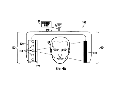
FIG_ 4A illustrates a schematic of an example multiple modality x-ray
imaging device of the present disclosure;
-6-
CA 03138277 2021- 11- 16
WO 2020/243383
PCT/US2020/035052
FIG. 4B and FIG. 4C are illustrations of a curved carbon nanotube
(CNT) x-ray source and a linear-shaped CNT x-ray source;
FIG. 5 illustrates a schematic of an example multiple-modality x-ray
imaging device of the present disclosure having a rotatable x-ray source;
5
FIG. 6 illustrates a schematic of an example multiple-
modality x-ray
imaging device of the present disclosure having a rotatable x-ray source and
intraoral x-ray detector;
FIG. 7 illustrates a schematic of an example multiple-modality x-ray
imaging device of the present disclosure having a collimation assembly; and
10
FIG. 8 illustrates a schematic of an example multiple-
modality x-ray
imaging device of the present disclosure having a central x-ray focal spot
that
is significantly larger than the other x-ray focal spots.
DETAILED DESCRIPTION
15
The subject matter of the present disclosure includes a
multiple
modality x-ray imaging device or system that is configured to perform cone-
beam computed tomography (CBCT) imaging, intraoral x-ray imaging, and/or
intraoral tomosynthesis imaging_ In some embodiments, the devices and
systems of the present disclosure can be used for, inter alia, the diagnosis
20 and detection of dental and oral lesions, caries, or other oral disease.
Referring to FIG. 4A, the x-ray imaging device or system 100 of the
present invention comprises a rotating gantry 140 that is connected to a
mechanical stand. In some embodiments, the gantry 140 can be connected
to or be in communication with a controller or control unit 106 comprising one
25
or more processors, computer readable media, and
executable instructions.
The gantry 140 can, in some embodiments, be powered by the control unit
106 or it can have its own independent power supply. The gantry 140 is
configured to rotate 360 degrees about an axis. In some embodiments, the
control unit 106 and/or the gantry 140 can comprise a power supply that
30
provides the necessary power to operate the x-ray imaging
device or system
100. In some embodiments, the gantry 140 comprises a first portion 102 and
a second portion 104 opposite the first portion. In some embodiments, the
first
portion 102 and the second portion 104 are spaced apart with respect to each
other such that a human or other subject can be positioned under the rotating
-7-
CA 03138277 2021- 11- 16
WO 2020/243383
PCT/US2020/035052
axis of the gantry 140 and between the first portion 102 and the second
portion
104. In either case, both the first portion 102 and the second portion 104 are
configured such that different devices can be attached to them.
In some embodiments, the x-ray imaging device or system 100 is
based on a computed tomography (CT) scanner, wherein the conventional
single-beam x-ray tube is replaced with an x-ray source array 120 comprising
a plurality of spatially distributed and individually controllable x-ray focal
spots
150. In some embodiments, the spatially distributed x-ray source array 120
can be pivotably attached to the first portion 102 of the gantry 140. In some
embodiments, a digital area x-ray detector 110 can be attached to the second
portion 104 on an opposite side of the x-ray source array 120. In some
embodiments, a collimation assembly 122 can be provided the collimation
assembly 122 comprising a collimator which is configured to substantially
collimate the x-ray radiation generated from the x-ray source array 120. In
some embodiments, the collimation assembly 122 is adjustable and is
configured to shape the x-ray radiation into a cone-shaped beam. In some
embodiments, the collimation assembly 122 is configured such that an angle
of the cone-shaped beam that is generated by the x-ray source array 120 can
be changed. In some embodiments the x-ray imaging device or system 100,
via the control unit 106, is configured to operate in a cone-beam computed
tomography (CBCT) imaging mode, an intraoral x-ray imaging mode, and/or
an intraoral tomosynthesis imaging mode.
In some embodiments of the present disclosure, the x-ray source array
120 comprises a carbon nanotube (CNT) based field emission x-ray source
array. A CNT x-ray source array utilizes an array of individually controllable
CNT field emitters to generate electrons at room temperature, wherein the
electrons are accelerated to bombard the anode to produce x-rays from
multiple focal spots on either one extended x-ray anode or multiple x-ray
anodes. In some embodiments of the present disclosure, the CNT field
emitters are connected to an electronic switching device. By electronically
switching the individual CNT cathodes on and off, a scanning x-ray beam can
be produced from different viewing angles to collect a plurality of projection
images. FIG. 4B illustrates this principle. In some embodiments, the CNT x-
-8-
CA 03138277 2021- 11- 16
WO 2020/243383
PCT/US2020/035052
ray source array can be arranged in a curved fashion, such as shown in, for
example without limitation, FIG. 4B. However, in some embodiments the CNT
x-ray source array does not have to be shaped in a curved manner but can be
straight or linear. Such a straight or linearly shaped CNT x-ray source array
is
5 illustrated in FIG. 4C.
With CNTs, electrons are produced at room temperature using field
emission. By applying an electrical potential difference across a very sharp
object, electrons may be produced at the tip of the sharp object. One
requirement of x-ray imaging with modem x-ray tubes and CNTs includes
10 focusing of each of the electron sources. In 2002, Zhou, Lu, and
colleagues
demonstrated that CNTs could serve as effective field emitters for x-ray
sources, due to their atomically sharp tips and high mechanical stability. The
CNT x-ray sources can be positioned in close proximity, allowing the creation
of multi-beam x-ray sources for a variety of applications.
15
The electron field emission x-ray source and x-ray source
array
technologies were initially disclosed in several U.S. patents including
US 6,553,096 entitled "X-ray Generating Mechanism Using Electron Field
Emission Cathode", US 6,850,595, and US 6,876,724.
In some embodiments, the x-ray imaging device or system 100
20 comprises between, and including, about three and sixty individually
controllable CNT emitters as electron sources. In some embodiments, the x-
ray source array has a unipolar design. In some embodiments, the x-ray
source array has an anode voltage of between, and including, about 10 kV
and 120kV and an x-ray tube current of between, and including, about 1 mA
25 and 30 mA.
CNT based field emission x-ray source arrays for different imaging
applications including medical and securities have been commercially
produced by companies including Xin Ray Systems and more recently by
NuRay Technologies. The construction and performances of some CNT x-
30 ray source arrays have also been described in technical publications
including
Connor Puett et al. in "An Update on Carbon Nanotube-Enabled X-Ray
Sources for Biomedical Imaging", WIREs Nanomed Nanobiotechnology 2017,
-9-
CA 03138277 2021- 11- 16
WO 2020/243383
PCT/US2020/035052
e1475. doi: 10.1002/wnan.1475, the disclosure of which is expressly
incorporated by reference herein in its entirety.
The CNT x-ray source arrays for intraoral tomosynthesis was disclosed
in the commonly owned, patent applications and issued patents, which are
expressly incorporated by reference herein in their entireties: U.S. Patent
Numbers 9,907,520, issued March 6, 2018, entitled DIGITAL
TOMOSYNTHESIS SYSTEMS, METHODS, AND COMPUTER READABLE
MEDIA FOR INTRAORAL DENTAL TOMOSYNTHESIS IMAGING; and
9,782,136, issued October 10, 2017, entitled INTRAORAL
TOMOSYNTHESIS SYSTEMS, METHODS, AND COMPUTER READABLE
MEDIA FOR DENTAL IMAGING.
The intraoral tomosynthesis technology and the CNT x-ray source
array for intraoral tomosynthesis was also disclosed in the following
technical
publications, the disclosures of which are expressly incorporated herein by
reference in their entireties:
"Stationary Intra-Oral Digital Tomosynthesis Using A Carbon Nanotube
X-Ray Source Array", Jing Shan, Andrew W. Tucker, Laurence R. Gaalaas,
Gongting Wu, Enrique Platin, Andre Mol, Jianping Lu, Otto Zhou,
Dentomaxillofacial Radiology 44 (9), 20150098.
"Characterization And Preliminary Imaging Evaluation Of A Clinical
Prototype Stationary Intraoral Tomosynthesis System", Inscoe, C.R., Platin,
E., Mauriello, S.M., Broome, A., Mol, A., Gaalaas, L.R., Regan Anderson,
M.W., Puett, C., Lu, J. & Zhou, 0. 2018, Medical Physics, vol. 45, no. 11, pp.
5172-5185.
In some embodiments, the x-ray source array 120 is used for both
CBCT imaging and for intraoral imaging. As the x-ray source array 120 and
the digital area x-ray detector 110 rotate about the axis, they turn in a
circle,
which can be referred to as a source-detector rotation circle. As shown in
FIG.
4A, the plurality of x-ray focal spots 150 of the x-ray source array 120 can
be
aligned in an array which is parallel to a plane of the digital area x-ray
detector
110 and is perpendicular to a tangent direction of the source-detector
rotation
circle.
-10-
CA 03138277 2021- 11- 16
WO 2020/243383
PCT/US2020/035052
Cone Beam Computed Tomoaraphv (CBCT)
In some embodiments, when operating in the CBCT imaging mode, the
x-ray imaging device or system 100 can be configured to use x-ray radiation
from one x-ray focal spot of the plurality of x-ray focal spots 150 to capture
5 one or more images of an area of interest of a subject 130. In this
embodiment,
when only one x-ray focal spot is used, the cone-beam shaped x-ray radiation
beam generated by the one x-ray focal spot can have a wider-angle cone-
beam than individual x-ray focal spots when multiple x-ray focal spots are
used. The collimation assembly 122 is configured to ensure that cone angles
10 are wide or narrow enough depending on whether one x-ray focal spot is
used
or multiple. In order to capture images in the CBCT imaging mode, the x-ray
imaging device 100 is configured such that the x-ray source array 120 and the
digital area x-ray detector 110 can be rotated around the subject 130. While
operating in the CBCT imaging mode, the x-ray imaging device or system 100
15 is configured to pulse x-ray radiation from the one x-ray focal spot in
order to
illuminate the area of interest of the subject 130. The one or more x-ray
images
are recorded by the digital area x-ray detector 110.
In some embodiments, the digital area x-ray detector 110 is in
electronic communication with either the control unit 106 or some other
20 electronic device comprising one or more processors, such as a computer
or
workstation, one or more monitors, and/or one or more storage devices, such
as a hard drive or solid-state drive. In some embodiments, the digital area x-
ray detector 110 is in communication with the control unit 106 or the other
electronic device via a wireless or wired connection. In some embodiments,
25 the control unit 106, or some other controller comprising one or more
processors, is configured to program the x-ray source array 120 and/or the
digital area x-ray detector 110. In some embodiments, once the images have
been captured by the digital area x-ray detector 110 they can be transmitted
to the other controller or computer in electronic communication with the x-ray
30 imaging device or system 100 or the images can be sent to the control
unit
106 for processing, electronic storage, and/or displaying for a user of the
system.
-11-
CA 03138277 2021- 11- 16
WO 2020/243383
PCT/US2020/035052
FIG. 5 illustrates that the x-ray source array 120 is capable of rotating,
without a need for moving the gantry 140, to a proper position for the various
imaging modes. The benefit of this feature is that a more precise image
capture can be performed of the subject's area of interest. Additionally, the
5
rotating gantry 140 allows some flexibility in
positioning the x-ray source array
120 with respect to an intraoral sensor (described hereinbelow) for intraoral
tomosynthesis imaging. In some embodiments, the x-ray exposure from the
x-ray source array 120 is in synchronization with data collection by the
digital
area x-ray detector 110.
Intraoral Tomosvnthesis
Referring to FIG. 6, in some embodiments of the present disclosure,
the x-ray imaging device or system 100 is configured to operate in an
intraoral
tomosynthesis imaging mode. In the intraoral tomosynthesis imaging mode
15
the x-ray imaging device or system 100 is configured to
use the x-ray source
array 120 and a dynamic intraoral sensor 210 placed inside the subject's
mouth to capture images. Although FIG. 6 and FIG. 7 depict the dynamic
intraoral sensor 210 as being visible outside the subject's 130 mouth, the
intraoral sensor 210 would actually be placed inside the mouth. In some
embodiments, the intraoral sensor 210 can be flexible and can conform
substantially to a lingual surface of the teeth of a subject 130.
Additionally,
multiple x-ray beams generated from multiple focal spots of the plurality of
spatially distributed x-ray focal spots 150 are used to generate a series of
projection images of the area of interest of the subject 130. For example and
25
without limitation, two x-ray beams 220 and 230 from two
x-ray focal spots on
the anode are shown in FIG. 6. In some embodiments, the x-ray imaging
device or system 100 is configured align the x-ray source array 120 with the
dynamic intraoral sensor 210 within the subject's 130 mouth. In some
embodiments, in the intraoral tomosynthesis imaging mode, the x-ray imaging
device or system 100 is further configured to collimate x-ray radiation to a
surface of the dynamic intraoral sensor 210.
In some embodiments, the x-ray imaging device or system 100 is
configured to sequentially activate x-ray radiation from multiple x-ray focal
-12-
CA 03138277 2021- 11- 16
WO 2020/243383
PCT/US2020/035052
spots of the plurality of x-ray focal spots 150 to produce multiple projection
images from multiple viewing angles without any mechanical movement of the
x-ray source array 120 or the intraoral sensor 210.
The projection images are recorded by the intraoral x-ray sensor 210.
In some embodiments, the intraoral x-ray sensor 210 is in electronic
communication with the control unit 106 and/or some other processing unit,
computer, or device capable of processing or reconstructing the multiple
projection images into a tomosynthesis image stack. After the images have
been captured, the x-ray device or system 100 is configured to transmit the
images to the control unit 106 or other processing unit in electronic
communication with the intraoral x-ray sensor 210. The intraoral x-ray sensor
210 can be in electronic communication with the control unit 106 or other
processing unit via wired or wireless connection(s). The projection images are
then processed by the control unit 106 or other computer and used for
tomosynthesis reconstruction to process or reconstruct the multiple projection
images into a tomosynthesis image stack.
In some embodiments of the present disclosure, the x-ray imaging
device or system 100 is configured to perform a small-angle rotation (e.g.,
between, and including, about 5 and 30 degrees) of the x-ray source array
120 with respect to a central rotation axis of the gantry 140 while the
intraoral
sensor 210 remains stationary, thereby performing large angle intraoral
tomosynthesis imaging.
Furthermore, in some embodiments of the present disclosure, the x-ray
imaging device or system 100 is configured to perform a rotation of the x-ray
source array 120 and the digital area x-ray detector 110 with respect to a
central rotation axis of the gantry 140, thereby performing large angle
extraoral tomosynthesis imaging.
Two-Dimensional (2D) Intraoral !mai:dna
In some embodiments, the x-ray imaging device or system 100 is
configured to operate in a two-dimensional (20) intraoral x-ray imaging mode,
which is well known in the prior art. Those having ordinary skill in the art
will
appreciate that in 20 intraoral x-ray imaging mode, the x-ray imaging device
-13-
CA 03138277 2021- 11- 16
WO 2020/243383
PCT/US2020/035052
or system 100 is configured to use one of the x-ray focal spots 150 in
addition
to the intraoral sensor 210 to capture the 20 intraoral x-ray images of the
area
of interest of the subject 130.
Referring to FIG. 7, and in some embodiments, in the intraoral
tomosynthesis mode, an adjustable multi-beam collimator or collimation
assembly 122 is positioned between the x-ray source array 120 and the
subject 130. In some embodiments, the collimation assembly 122 is
configured to limit, affect, or filter radiation 330 from each of the x-ray
focal
spots 150 to substantially illuminate an area of the intraoral x-ray sensor
210
or the digital area x-ray detector 110 based on a mode of operation of the x-
ray imaging device or system. Furthermore, in some embodiments, the x-ray
source array 120 can be mounted on a degree-of-freedom structure 310 to
enable manipulation of the orientation and position of the x-ray source array
120 such that it can be aligned with the intraoral sensor 210 placed in the
subject's 130 mouth.
In some embodiments, the x-ray imaging device or system 100 of the
present disclosure comprises an energy control unit that can set the output
energy of the x-ray source 120 to different levels, depending on the imaging
need. For example and without limitation, the energy control unit can set the
voltage of the x-ray source array 120 to between, and including, about 50kV
and 200kV. Furthermore, in some embodiments, the energy control unit can
set the voltage to, for example and without limitation, between, and
including,
about 60kV and 70kV for intraoral x-ray imaging and between, and including,
about 60kV and 120kV for CBCT imaging. In some embodiments, the energy
control unit can be integrated into the control unit 106 or it can be a
separate
device that is in electronic communication with the x-ray source array 120.
In some embodiments, the device can further comprise a graphical-
user-interface, monitor, screen, or other device in electronic communication
with the control unit 106, that allows a user to choose the imaging modality
and the imaging protocol as well as view the images created by the x-ray
imaging device or system 100.
As illustrated in FIG. 8, in some embodiments, the x-ray source array
120 can comprise at least one larger x-ray focal spot 450 that has a first
focal
-14-
CA 03138277 2021- 11- 16
WO 2020/243383
PCT/US2020/035052
spot size and the remainder of the plurality of x-ray focal spots 150 have a
second focal spot size. In some embodiments, the first focal spot size of the
at least one x-ray focal spot 450 is a larger size (e.g., between, and
including,
about IEC 0.7 and IEC 1.3) than the second focal spot size (e.g., between,
5
and including, about IEC 0.3 and IEC 0.7). In one example
the larger x-ray
focal spot 450 can be used for CBCT imaging, whereas the smaller ones 150
can be used for intraoral tomosynthesis imaging and intraoral radiography. In
one example, the other x-ray focal spots 150 and the larger x-ray focal spot
450 are arranged in a linear fashion on the x-ray anode or anodes, as
10
illustrated in FIG. 8. In another example the focal spots
are arranged in a pre-
determined pattern on a plane, such as along the circumference of a circle.
In some aspects, standard two-dimensional intraoral x-ray radiographs
of the area of interest of the subject 130 can be obtained using the x-ray
radiation from one focal spot 150 of the x-ray source array 120.
15
In some embodiments of the present disclosure, the x-ray
source array
120 is a carbon nanotube-based field emission x-ray source array.
The present subject matter can be embodied in other forms without
departure from the spirit and essential characteristics thereof. The
embodiments described therefore are to be considered in all respects as
20
illustrative and not restrictive. Although the present
subject matter has been
described in terms of certain specific embodiments, other embodiments that
are apparent to those of ordinary skill in the art are also within the scope
of
the present subject matter.
-15-
CA 03138277 2021- 11- 16