Note: Descriptions are shown in the official language in which they were submitted.
HVAC SYSTEM
FIELD
[0001] This application relates to the field of HVAC systems in a
multi-unit
building and in particular, to systems having multiple heat exchangers for
temperature
control in a building. This application also relates to a HVAC system for a
single unit,
which may be a condominium, a house or a multiroom commercial facility.
INTRODUCTION
[0002] The following is not an admission that anything discussed
below is part of
the prior art or part of the common general knowledge of a person skilled in
the art.
[0003] A fan coil is a component part of many residential, commercial, and
industrial heating, ventilation and air conditioning (HVAC) systems, which
provides
treated (e.g., heated and/or cooled) air to a room in which they are installed
or to
multiple rooms. A fan coil comprises a heating and/or cooling heat exchanger
and a fan.
Air to be heated or cooled is introduced into the heat exchanger and cooled or
heated
by ambient air that is to be exhausted from the room. The fan coil may be
controlled
automatically by a thermostat which may activate the fan coil as required to
maintain a
set air temperature in the room.
[0004] Conventional environmental control systems may experience
certain
disadvantages, such as distributing heated or cooled air throughout a
structure
unnecessarily, unevenly or consuming excessive energy when attempting to
achieve
selected temperatures in different locations within a structure. There is a
need to
improve such environmental control systems to reduce these and other
disadvantages.
SUMMARY
[0005] In accordance with one aspect of this disclosure, an
intermediary fluid is
utilized to transfer heat between a single unit (such as a condominium or an
office) and
a riser stack. The intermediary fluid may flow between a central source (such
as a riser
stack in a multi-unit building) and the HVAC system in the single unit.
Accordingly, a
continuous closed loop flow path may extend from the central source and the
HVAC
system in the single unit, and then back to the central source. An advantage
of this
- 1 -
Date recue / Date received 202 1-1 1-08
design is that a low volume, low pressure fluid may be used as the
intermediary fluid
(which may be referred to as a closed loop fluid) and may be isolated from the
riser,
which operates under higher pressure. Isolating the closed loop from the riser
may
reduce the likelihood of damage to the building in the event of a leak because
there is a
lower volume of fluid that circulates exterior to the riser stack and that may
travel across
a part of a floor in a building and the fluid operates under a low pressure.
[0006] In accordance with this aspect, there is provided a multi-unit
building
HVAC system comprising:
a) a riser stack in flow communication with a closed loop fluid; and,
b) a first single unit HVAC system comprising:
i. a first heat exchanger thermally connected to the riser stack
ii. a second heat exchanger thermally connected to a fluid distribution system
within
the unit; and,
iii. a closed loop fluid flow path extending between the first and second heat
exchangers,
whereby the first heat exchanger exchanges heat between a riser stack fluid in
the riser
stack and the closed loop fluid in the closed loop fluid flow path and the
second heat
exchanger exchanges heat between the closed loop fluid and a distribution
fluid of the
fluid distribution system.
[0007] In any embodiment, the closed loop fluid may be a liquid and the
distribution fluid may comprise air.
[0008] In any embodiment, the closed loop fluid may be a liquid and
the closed
loop fluid flow path may utilize 1 -200 L, 2 - 100 L or 5 -20 L of the closed
loop fluid,
which may be at a pressure of 1 - 30 psi or 5-15 psi.
[0009] In any embodiment, the riser fluid may be at a pressure of at least
100 psi,
150psi, 200 psi or more.
[0010] In any embodiment, a floor in a building may have at least a
first unit and a
second unit, the first single unit HVAC system may provide temperature
modulation to
- 2 -
Date recue / Date received 202 1-1 1-08
the first unit and a second single unit HVAC system may provide temperature
modulation to the second unit.
[0011] In any embodiment, a floor in a building may have at least a
first unit and
the first single unit HVAC system may provide temperature modulation to the
first unit
and the riser stack may be exterior to the first unit.
[0012] In any embodiment, the riser may be provided interior of a
liner conduit.
[0013] In any embodiment, the multi-unit building HVAC system may
further
comprise a riser leak detector which may issue a signal that terminates flow
in the riser
stack upon a leak in the riser stack being detected.
[0014] In any embodiment, the riser leak detector may comprise at least one
of a
float switch and a conductivity sensor.
[0015] In any embodiment, the multi-unit building HVAC system may
further
comprise a closed loop high pressure sensor which may issue a signal that
terminates
flow in the closed loop fluid flow path upon a high pressure condition being
detected.
[0016] In any embodiment, the multi-unit building HVAC system may further
comprise a closed loop leak detector which may issues a signal that terminates
flow in
the closed loop fluid flow path upon a leak in the closed loop fluid flow path
being
detected.
[0017] In any embodiment, the multi-unit building HVAC system may
further
comprise a capacitance leak detector wherein, upon occurrence of a leak, the
capacitance leak detector may issue a signal that terminates flow in the riser
stack if the
capacitance leak detector detects a fluid having a capacitance above a present
capacitance that is indicative of the riser fluid and the capacitance leak
detector issues
a signal that terminates flow in the closed loop fluid flow path if the
capacitance leak
detector detects a fluid having a capacitance below the present capacitance
that is
indicative of the closed loop fluid.
[0018] In any embodiment, a floor in a building may have at least a
first unit, the
unit may have a first room and a second room, the second heat exchanger may
provide
- 3 -
Date recue / Date received 202 1-1 1-08
temperature modulation to the first room and the first single unit HVAC system
may
comprise a third heat exchanger that may provide temperature modulation to the
second room and the third heat exchanger may exchange heat between the closed
loop
fluid and the distribution fluid of the fluid distribution system.
[0019] In any embodiment, a floor in a building may have at least a first
unit and
the fluid distribution system may comprise a fluid conduit that extends
between the
second heat exchanger and a room of the first unit.
[0020] In any embodiment, a floor in a building may have at least a
first unit and
the fluid distribution system may comprise a fluid conduit that extends
between the
second heat exchanger and a plurality of rooms of the first unit.
[0021] In any embodiment the closed loop fluid may be a liquid and
the closed
loop fluid flow path may comprise a conduit having a wall thickness of 0.01 to
0.06
inches or0.02 to 0.04 inches.
[0022] In any embodiment, the conduit may be metal.
[0023] In accordance with another aspect of this disclosure, a fan coil is
provided
with a heat exchanger having a modulation fluid flow path and a unit air
distribution flow
path. The fan coil has a motor and fan assembly for distributing a
distribution fluid into a
unit of a building. An advantage of this design is that the fan coil may be
isolated from a
thermal source, such as a riser, that operates at a higher pressure than the
modulation
fluid in the fan coil. Accordingly, the heat exchanger may utilize thinner
walled conduits,
thereby enabling the heat exchanger to have a higher heat transfer rate.
Further, the
risk of damage to a building containing the fan coil is reduced, since the
modulation fluid
that circulates exterior to the riser stack and that may travel across a part
of a floor in a
building may operate at a lower volume and pressure than the thermal source.
[0024] In accordance with this aspect, there is provided a fan coil
comprising:
a) a heat exchanger comprising a modulation fluid flow path and a unit air
distribution flow path, the unit air distribution flow path has an inlet for
receiving
air from a room and an outlet for delivering temperature modulated air,
wherein
- 4 -
Date recue / Date received 202 1-1 1-08
the modulation fluid flow path is operable to receive a fluid that is at a
pressure of
up to 50 psi; and,
b) a first motor and fan assembly in the unit air distribution flow path.
[0025]
In accordance with another aspect of this disclosure, the unit air
distribution flow path has a lower port positioned adjacent a floor of a room
and an
upper port positioned adjacent a ceiling of a room and the motor and fan
assembly is
reversible between a first mode to direct air through the upper port and a
second mode
to direct air through the lower port. An advantage of this design is that the
fan coil
system air flow path may be reversed depending on the ambient environment of
the
room. For example, during winter, hot air from the ceiling may be exhausted
through the
lower port to heat the room more efficiently and during summer, cool air from
the floor
may be exhausted through the upper port to cool the room more efficiently.
[0026]
In accordance with this aspect, there is provided a fan coil system
comprising:
a) a heat exchanger comprising a modulation fluid flow path and a unit air
distribution flow path, the unit air distribution flow path has an inlet for
receiving
air from a room and an outlet for delivering temperature modulated air, the
modulation fluid flow path is connectable with a source of heating or cooling
fluid;
and,
b) a first reversing motor and fan assembly in the unit air distribution flow
path,
wherein the unit air distribution flow path has a lower port positioned to be
adjacent a
floor of a room and an upper port positioned to be adjacent a ceiling of a
room, and the
first reversing motor and fan assembly is operable in a first mode to direct
air through
the upper port and is also operable in a second mode to direct air through the
lower
port, wherein, in the first mode, the lower port functions as the inlet and
the upper port
functions as the outlet and in the second mode the upper port functions as the
inlet and
the lower port functions as the outlet.
[0027]
In accordance with another aspect of this disclosure, the fan coil is
provided behind a wall of a unit in the building and between two studs of the
wall. An
- 5 -
Date recue / Date received 202 1-1 1-08
advantage of this design is that the fan coil is small enough to fit flush, or
mostly flush,
with the wall of the unit, without extending into the floor space of the unit.
Accordingly,
the fan coil footprint is reduced, and need not take up floor space of the
unit. For
example, instead of a conventional fan coil that takes up floor space in a
corner of the
unit, the fan coil may be hidden in the wall to increase the usable area of
the unit.
[0028] In accordance with this aspect, there is provided a building
comprising a
first unit, the first unit having a fan coil comprising a heat exchanger and a
motor and
fan assembly wherein the fan coil is positioned behind a wall and between two
studs of
the unit.
[0029] In accordance with another aspect of this disclosure, the HVAC
system is
provided with a fan coil that is positioned in a wall separating a first room
and a second
room. An advantage of this design is that a single fan coil may be used to
supply air to
multiple rooms. Another advantage is that the amount of air provided to each
room may
be controlled by the fan coil to better achieve a desired room temperature in
each room.
[0030] In accordance with this aspect, there is provided a building
comprising a
first unit, the first unit having a first HVAC system, a first room and an
adjacent second
room, the first HVAC system comprising a fan coil positioned in a wall
separating the
first and second rooms, each room having an air return and an air outlet from
the fan
coil wherein the fan coil is in flow communication with the air return of each
room and is
also in flow communication with the air outlet of each room.
[0031] In accordance with another aspect of this disclosure, an HVAC
system is
provided with a fan coil having a movable portion that is located within an
air distribution
flow path (e.g., an air flow duct leading to or from the fan coil). An
advantage of this
design is that the movable portion of the fan coil (e.g., the motor and fan
assembly, the
heat exchanger or optionally the entire fan coil) may be moved within the flow
path to an
access point in a wall, such as the air return or the air outlet. Moving the
movable
portion to an access point may allow for the fan coil to be located behind a
wall (e.g.,
behind a sheet of drywall) while enabling maintenance and/or cleaning of the
moveable
portion.
- 6 -
Date recue / Date received 202 1-1 1-08
[0032]
In accordance with this aspect, there is provided a building comprising a
first unit, the first unit having an HVAC system comprising a fan coil
positioned in a wall
and an air distribution flow path, the air distribution flow path comprising
an air return
and an air outlet wherein at least a portion of the fan coil is movably
mounted within the
air distribution flow path to a position in which the fan coil is located at
one of the air
return and the air outlet.
[0033]
In accordance with another aspect of this disclosure, a fan coil system is
provided with a first motor and fan assembly and a second motor and fan
assembly. An
advantage of this design is that the rate of rotation of the fan of each motor
and fan
assembly may be reduced without reducing the overall air flow rate of the fan
coil
system. Reducing the rate of rotation of the fan of each motor and fan
assembly may
reduce the power required to achieve the desired flow rate, reduce the noise
associated
with the system and increase the lifetime of the motor and fan assemblies.
[0034]
In accordance with this aspect, there is provided a fan coil system
comprising:
a) a heat exchanger comprising a modulation fluid flow path and an air
distribution
flow path, the air distribution flow path has a first port and a second port,
the
modulation fluid flow path is connectable with a source of heating or cooling
fluid;
b) a first motor and fan assembly in the unit air distribution flow path
wherein the
first motor and fan assembly is operable to draw air from the first port and
to
direct air out through the second port whereby the first port functions as an
air
return of the air distribution flow path and the second port functions as an
air
outlet of the air distribution flow path; and,
c) a second motor and fan assembly in the unit air distribution flow path
wherein the
second motor and fan assembly is operable to draw air from the second port and
to direct air out through the first port whereby the second port functions as
an air
return of the air distribution flow path and the first port functions as an
air outlet of
the air distribution flow path.
- 7 -
Date recue / Date received 202 1-1 1-08
[0035]
In accordance with another aspect of this disclosure, a single unit HVAC
system uses a plurality of modulation fluid flow paths to provide to heat or
cool different
rooms or different locations in an open space. Accordingly, a single closed
loop flow
path may extend between a riser stack and a unit and the closed loop flow path
may
extend (e.g., it may split into different sub-loops within the unit or may be
a continuous
loop that passes through two or more rooms) to heat exchangers in flow
communication
with different rooms or parts of a room. Alternately, a plurality of closed
loop flow paths
may extend between a riser stack and the unit. For example, a first
temperature sensor
may be operable to monitor the temperature of a first room and a second
temperature
sensor may be operable to monitor the temperature of a second room. Each room
may
have a heat exchanger and the amount of heating or cooling that is provided to
each
room may be adjusted by adjusting the amount of fluid flowing to each heat
exchanger
and/or the rate of closed loop fluid flowing to each heat exchanger and/or the
amount of
air flowing into each room for the heat exchanger. An advantage of this design
is that
the temperature of each room may be independently controlled by its respective
temperature sensor to achieve separate desired temperatures for each room.
[0036]
In accordance with this aspect, there is provided an HVAC system for a
single unit having a first room and a second room, the HVAC system comprising:
a) a first heat exchanger comprising a first modulation fluid flow path and a
first
room air distribution flow path, the first room air distribution flow path has
an inlet
for receiving air and an air outlet for delivering temperature modulated air
to the
first room with a first motor and fan assembly provided in the first room air
distribution flow path;
b) a first temperature sensor operable to monitor a temperature of the first
room,
wherein the air outlet of the first room comprises a first adjustable damper
and
the first damper is adjustable based on a signal from the first temperature
sensor;
c) a second heat exchanger comprising a second modulation fluid flow path and
a
second room air distribution flow path, the second room air distribution flow
path
has an inlet for receiving air and an air outlet for delivering temperature
- 8 -
Date recue / Date received 202 1-1 1-08
modulated air to the second room with a second motor and fan assembly
provided in the second room air distribution flow path; and,
d) a second temperature sensor operable to monitor a temperature of the second
room, wherein the air outlet of the second room comprises a second adjustable
damper and the second damper is adjustable based on a signal from the second
temperature sensor,
wherein the first and second modulation fluid flow paths are operable to
receive a fluid
that is at a pressure of up to 50 psi.
[0037]
In accordance with this aspect, there is also provided an HVAC system for
a single unit having a first room and a second room, the HVAC system
comprising:
a) a first heat exchanger comprising a first modulation fluid flow path and a
first
room air distribution flow path, the first room air distribution flow path has
an inlet
for receiving air and an air outlet for delivering temperature modulated air
to the
first room with a first motor and fan assembly provided in the first room air
distribution flow path;
b) a first temperature sensor operable to monitor a temperature of the first
room;
c) a second heat exchanger comprising a second modulation fluid flow path and
a
second room air distribution flow path, the second room air distribution flow
path
has an inlet for receiving air and an air outlet for delivering temperature
modulated air to the second room with a second motor and fan assembly
provided in the second room air distribution flow path; and,
d) a second temperature sensor operable to monitor a temperature of the second
room,
wherein the first and second modulation fluid flow paths are part of a closed
loop fluid
flow path extending between the first and second heat exchangers and a riser
stack of a
building and a flow of fluid in the first modulation fluid flow path is
adjustable based on a
signal from the first temperature sensor.
- 9 -
Date recue / Date received 202 1-1 1-08
[0038]
In accordance with this aspect, there is also provided an HVAC system for
a single unit having a first room and a second room, the HVAC system
comprising:
a) a first heat exchanger comprising a first modulation fluid flow path and a
first
room air distribution flow path, the first room air distribution flow path has
an inlet
for receiving air and an air outlet for delivering temperature modulated air
to the
first room with a first motor and fan assembly provided in the first room air
distribution flow path;
b) a first temperature sensor operable to monitor a temperature of the first
room
wherein the first modulation fluid flow path is part of a first closed loop
fluid flow
path extending between the first heat exchanger and a riser stack of a
building
and a flow of fluid in the first modulation fluid flow path is adjustable
based on a
signal from the first temperature sensor;
c) a second heat exchanger comprising a second modulation fluid flow path and
a
second room air distribution flow path, the second room air distribution flow
path
has an inlet for receiving air and an air outlet for delivering temperature
modulated air to the second room with a second motor and fan assembly
provided in the second room air distribution flow path; and,
d) a second temperature sensor operable to monitor a temperature of the second
room, wherein the second modulation fluid flow path is part of a second closed
loop fluid flow path extending between the second heat exchanger and a riser
stack of a building and a flow of fluid in the second modulation fluid flow
path is
adjustable based on a signal from the second temperature sensor.
[0039]
In accordance with another aspect of this disclosure, an HVAC system is
provided with a heat retaining member in thermal communication with a
modulation fluid
flow path of a heat exchanger. An advantage of this design is that the heat
retaining
member may be used to store thermal energy (e.g., from the sun), thereby more
efficiently modulating the temperature of one or more rooms in the HVAC
system.
Another advantage is that the heat retaining member may be thermally charged
by an
- 10 -
Date recue / Date received 202 1-1 1-08
outside source, such as a solar-powered source to conserve energy in the HVAC
system.
[0040]
In accordance with this aspect, there is provided an HVAC system
comprising:
a) a heat exchanger comprising a modulation fluid flow path and an air
distribution
flow path, the air distribution flow path has an inlet for receiving air and
an air
outlet for delivering temperature modulated air;
b) a first motor and fan assembly provided in the air distribution flow path;
and,
c) a heat retaining member in thermal communication with the modulation fluid
flow
path, wherein the heat retaining member comprises a solid material.
[0041]
In accordance with another aspect of this disclosure, a ventilation system
is provided comprising an air treatment apparatus (e.g., a fan coil), which is
operable to
move air within a volume (e.g., a room in a house, a house, a condominium, a
factory,
office space or the like) and an oxygen concentrator operable in an oxygen
enrichment
mode to enhance the level of oxygen in air which exits the air treatment
apparatus and
is introduced into the volume. Optionally, the oxygen concentrator may
transfer oxygen
from air which is to be exhausted from the volume (exhaust air) and deliver at
least
some of that oxygen to the air that is to be outputted from the air treatment
apparatus.
For example, a fan coil may include an air-to-air heat exchanger and part of
the return
air may be exhausted as exhaust air. Oxygen may be removed from the exhaust
air and
delivered to the return air that is to be outputted from the air treatment
apparatus into
the volume. An advantage of this design is that the air that is outputted from
the air
treatment apparatus may be enriched with oxygen from the exhaust air, thereby
recycling oxygen from the exhaust air.
[0042]
In accordance with this aspect, there is provided an HVAC system
comprising:
a fan coil having an exhaust air outlet port through which exhaust air exits
the fan
coil and an air inlet port through which input air enters the fan coil; and,
-11 -
Date recue / Date received 202 1-1 1-08
an oxygen concentrator operable in an oxygen enrichment mode to transfer
oxygen from the exhaust air and deliver the oxygen to the input air.
[0043] In any embodiment, the oxygen concentrator may be a
regenerable
oxygen concentrator.
[0044] In any embodiment, the oxygen concentrator may be a pressure swing
adsorption oxygen concentrator.
[0045] In any embodiment, in the oxygen enrichment mode, the oxygen
concentrator may adsorb nitrogen from the exhaust air using a molecular sieve
thereby
providing oxygen enriched air and the oxygen enriched air may be combined with
the
input air.
[0046] In any embodiment, the oxygen concentrator may also be
operable in a
regeneration mode wherein the nitrogen is desorbed from the molecular sieve.
[0047] In any embodiment, fan coil may be part of a HRV or ERV unit
and the
oxygen concentrator may be part of the HRV or ERV unit.
[0048] In any embodiment, the HVAC system may further comprise an oxygen
sensor operably connected to the oxygen concentrator whereby the oxygen
concentrator may be actuated when the oxygen sensor detects an oxygen level
below a
predetermined level.
[0049] In any embodiment, the oxygen concentrator may be deactivated
when
the oxygen sensor detects an oxygen level above a predetermined level.
[0050] In any embodiment, the oxygen concentrator may be connected in
flow
communication with the exhaust air outlet port and the input air inlet port.
[0051] In any embodiment, the oxygen concentrator may receive a bleed
stream
of the exhaust air.
[0052] In any embodiment, the fan coil may include a heat exchanger and the
oxygen concentrator may be connected in flow communication with the input air
upstream of the heat exchanger.
- 12 -
Date recue / Date received 2021-11-08
[0053] In
any embodiment, the HVAC system may further comprise a filter
positioned upstream of the oxygen concentrator.
[0054] In
accordance with another aspect of this disclosure, an air treatment
apparatus for an enclosed living space is providing having an air flow path
extending
from an air inlet to an air outlet with an oxygen concentrator in the air flow
path. The
oxygen concentrator is operable in an oxygen enrichment mode for removing
nitrogen
from air entering the air inlet of the air treatment apparatus and a
regeneration mode for
purging the nitrogen captured by the oxygen concentrator to a location
exterior to the
living space. An advantage of this design is that the oxygen concentration of
stale air
entering the air treatment apparatus may be increased before it is returned to
the
enclosed space, thereby improving the air quality of the living space.
[0055] In
accordance with this aspect, there is provided an air treatment
apparatus for an enclosed living space comprising an air flow path extending
from an air
inlet to an air outlet with an oxygen concentrator and an air moving member
provided in
the air flow
path, wherein the oxygen concentrator is operable in an oxygen enrichment
mode in which nitrogen is removed from air entering the air inlet and oxygen
enriched
air is exhausted from the air outlet and the oxygen concentrator is also
operable in a
regeneration mode wherein the nitrogen that was removed from air entering the
air inlet
is exhausted at a location exterior to the living space.
[0056] In any
embodiment, the apparatus may be portable whereby the
apparatus may be operated in the oxygen enrichment mode when located in the
living
space and the apparatus may be operated in the regeneration mode when located
exterior to the living space.
[0057] In
any embodiment, the apparatus may have an inlet conduit which may
extend from
a location exterior to the living space to the air inlet whereby, in the
oxygen
enrichment mode, fresh air may be drawn into the inlet conduit from exterior
to the living
space and oxygen enriched air may exit the air outlet to the living space.
[0058] In
any embodiment, the apparatus may have an outlet conduit which
extends from an exhaust outlet to a location exterior to the living space
whereby, in the
- 13 -
Date recue / Date received 2021-11-08
regeneration mode, nitrogen that was removed from air entering the inlet
conduit may
be exhausted through the outlet conduit to the location exterior to the living
space.
[0059] In any embodiment, the HVAC system may further comprise a
filter
positioned upstream of the oxygen concentrator.
[0060] In any embodiment, the HVAC system may further comprise a wall mount
or a window mount.
[0061] These and other aspects and features of various embodiments
will be
described in greater detail below.
BRIEF DESCRIPTION OF THE DRAWINGS
[0062] For a better understanding of the described embodiments and to show
more clearly how they may be carried into effect, reference will now be made,
by way of
example, to the accompanying drawings in which:
[0063] FIG. 1 is a front perspective view of a fan coil of an HVAC
system;
[0064] FIG. 2 is a rear perspective view of the fan coil of FIG. 1;
[0065] FIG. 3 is a front perspective view of the fan coil of FIG. 1 with
the front
panel removed;
[0066] FIG. 4 is a front view of the fan coil of FIG. 1 with the
front panel removed
so as to show the interior of the fan coil;
[0067] FIG. 5 is a schematic drawing of a fan coil with an oxygen
concentrator
operating in an oxygen enhancement mode;
[0068] FIG. 6 is a schematic of the fan coil of FIG. 5 operating in a
regeneration
mode; and,
[0069] FIG. 7 is a schematic of another fan coil with an oxygen
concentrator
operating in an oxygen enhancement mode;
[0070] FIG. 8 is a schematic of the fan coil of FIG. 7 operating in a
regeneration
mode; and,
- 14 -
Date recue / Date received 2021-11-08
[0071] FIG. 9 is a schematic drawing of a portable oxygen enrichment
apparatus
400;
[0072] FIG. 10 is an exemplary embodiment of a building having
multiple risers;
[0073] FIG. 11 is a floor plan of the building of FIG. 1 exemplifying
multiple units
on the floor, each of which has its own HVAC system and closed loop flow path;
[0074] FIG. 12 is a perspective view of a single unit HVAC system of
FIG. 2;
[0075] FIG. 13A is a floor plan of a single unit with a single unit
HVAC system
comprising three fan coils;
[0076] FIG. 13B is a floor plan of a single unit with a single unit
HVAC system
comprising two fan coils;
[0077] FIG. 14A is a front view of a single unit HVAC system
installed within a
wall;
[0078] FIG. 14B is a front view of the single unit HVAC system of
FIG. 5A with a
front panel (optionally drywall) removed;
[0079] FIG. 15 is a schematic view of a single unit HVAC system in fluid
communication with hot and cold risers;
[0080] FIG. 16 is a schematic view of another single unit HVAC system
in fluid
communication with hot and cold risers;
[0081] FIG. 17 is a side view of a single unit HVAC system positioned
in a wall
between two rooms;
[0082] FIG. 18 is a top view of the single unit HVAC system of FIG. 8
installed in
a wall between two rooms, and
[0083] FIG. 19 is a schematic view of another single unit HVAC system
in fluid
communication with a heat retaining member.
[0084] The drawings included herewith are for illustrating various examples
of
articles, methods, and apparatuses of the teaching of the present
specification and are
not intended to limit the scope of what is taught in any way.
- 15 -
Date recue / Date received 202 1-1 1-08
DESCRIPTION OF EXAMPLE EMBODIMENTS
[0085] Various apparatuses, methods and compositions are described
below to
provide an example of an embodiment of each claimed invention. No embodiment
described below limits any claimed invention and any claimed invention may
cover
apparatuses and methods that differ from those described below. The claimed
inventions are not limited to apparatuses, methods and compositions having all
of the
features of any one apparatus, method or composition described below or to
features
common to multiple or all of the apparatuses, methods or compositions
described
below. It is possible that an apparatus, method or composition described below
is not an
embodiment of any claimed invention. Any invention disclosed in an apparatus,
method
or composition described below that is not claimed in this document may be the
subject
matter of another protective instrument, for example, a continuing patent
application,
and the applicant(s), inventor(s) and/or owner(s) do not intend to abandon,
disclaim, or
dedicate to the public any such invention by its disclosure in this document.
[0086] The terms "an embodiment," "embodiment," "embodiments," "the
embodiment," "the embodiments," "one or more embodiments," "some embodiments,"
and "one embodiment" mean "one or more (but not all) embodiments of the
present
invention(s)," unless expressly specified otherwise.
[0087] The terms "including," "comprising" and variations thereof
mean "including
but not limited to," unless expressly specified otherwise. A listing of items
does not imply
that any or all of the items are mutually exclusive, unless expressly
specified otherwise.
The terms "a," "an" and "the" mean "one or more," unless expressly specified
otherwise.
[0088] As used herein and in the claims, two or more parts are said
to be
"coupled", "connected", "attached", or "fastened" where the parts are joined
or operate
together either directly or indirectly (i.e., through one or more intermediate
parts), so
long as a link occurs. As used herein and in the claims, two or more parts are
said to be
"directly coupled", "directly connected", "directly attached", or "directly
fastened" where
the parts are connected in physical contact with each other. None of the terms
"coupled", "connected", "attached", and "fastened" distinguish the manner in
which two
or more parts are joined together.
- 16 -
Date recue / Date received 2021-11-08
[0089] Furthermore, it will be appreciated that for simplicity and
clarity of
illustration, where considered appropriate, reference numerals may be repeated
among
the figures to indicate corresponding or analogous elements. In addition,
numerous
specific details are set forth in order to provide a thorough understanding of
the example
embodiments described herein. However, it will be understood by those of
ordinary skill
in the art that the example embodiments described herein may be practiced
without
these specific details. In other instances, well-known methods, procedures,
and
components have not been described in detail so as not to obscure the example
embodiments described herein. Also, the description is not to be considered as
limiting
the scope of the example embodiments described herein.
[0090] As used herein, the wording "and/or" is intended to represent
an inclusive
- or. That is, "X and/or Y" is intended to mean X or Y or both, for example.
As a further
example, "X, Y, and/or Z" is intended to mean X or Y or Z or any combination
thereof.
[0091] As used herein and in the claims, two elements are said to be
"parallel"
where those elements are parallel and spaced apart, or where those elements
are
collinear.
General Description of a Fan Coil
[0092] The following is a general description a fan coil for use in
an HVAC
system.
[0093] Figures 1 and 2 exemplify the use of a fan coil 100, as an oxygen
enrichment apparatus. In the illustrated example, fan coil 100 includes a
housing 104
including a front face 108 defining an air inlet 112 and an air outlet 116.
The fan coil 100
is operable to receive air from air inlet 112, heat or cool the air introduced
from inlet 112
and optionally, in addition or alternately, humidify the air, and discharge
the treated air
through air outlet 116 into a volume. The volume may be a room (e.g., a room
in a
house), a house, a condominium, a factory, office space or the like). For
convenience,
the volume is referred to herein as room 300.
[0094] The example shown includes a housing 104 that is substantially
cuboid
(i.e. box-shaped). An advantage of this design is that it provides an
efficient and
- 17 -
Date recue / Date received 2021-11-08
convenient form factor for applications where the fan coil 100 is recessed
into a flat wall.
However, in alternative embodiments, fan coil housing 104 can have any size
and
shape best suited for the intended application.
[0095] In the example shown, the fan coil inlet and outlet 112 and
116 are formed
in the front face 108 of the fan coil housing 104. This design provides an
efficient self-
contained apparatus 100 that can be easily accommodated into a room design.
However, in alternative embodiments, the fan coil inlet 112, the fan coil
outlet 116, or
both may be located remotely from the fan coil housing 104. For example, the
fan coil
inlet 112 and the fan coil outlet 116 may be fluidly connected to the fan coil
housing 104
by one or more airflow conduits to allow the fan coil 100 to service one or
more rooms
remote from the fan coil 100 (e.g., via ducting built into a wall or ceiling
of a building). In
accordance with such an example, the fan coil may be a furnace for a house,
factory,
office building or the like. In some embodiments, fan coil 100 may include a
plurality of
fan coil air inlets 112, a plurality of fan coil air outlets 116, or a
plurality of fan coil air
inlets 112 and a plurality of fan coil air outlets 116. For example, fan coil
100 may
include a plurality of fan coil air outlets 116 directed to different rooms.
This allows one
fan coil 100 to service several rooms.
[0096] Still referring to Figures 1 and 2, an air regulating device
120 is shown
connected to fan coil 100. The air regulating device 120 may operate as a
thermostat
and/or a hygrostat, capable of sensing air temperature and/or air humidity,
and signaling
the fan coil 100 to generate heated, cooled and/or humidified air in order to
maintain the
room air at a set temperature and/or humidity.
[0097] For example, the air regulating device 120 may be programmed
to
maintain the room air at 21 C and 40% relative humidity for comfortable human
occupancy. Air regulating device 120 can be any thermostat and/or hygrostat
device
known in the art and may be connected to the fan coil by any means (e.g.,
wires, Wi-Fi,
Bluetooth, or the like). In the illustrated embodiment, air regulating device
120 includes
inputs 124 for user interaction (e.g. buttons to enter a set air temperature
and relative
humidity), and an optional display 128 (e.g. to display the current air
temperature and
relative hum id ity).
- 18 -
Date recue / Date received 202 1-1 1-08
[0098] Reference is now made to Figures 3-4 which shows fan coil 100
with front
face 108 (Figure 1) removed so that some of the internal components are
visible. It will
be appreciated that the fan coil may be of any design known in the art and may
use any
flow path, and any heating unit and/or air conditioning unit and/or
dehumidification unit
known in the heating and cooling arts. As exemplified, fan coil 100 includes
an air
moving member 132 (e.g., a blower) and an air flow path 136 which extends the
air inlet
112, through the temperature regulation (e.g., heating) zone 150 having a heat
exchanger 154, through the air moving member 132, and from the air moving
member
outlet 140 through the humidification zone 158 to the fan coil air outlet 116.
[0099] As exemplified in FIGS. 3 and 4, fan coil 100 is shown including a
humidification unit 164 having a humidification outlet tube 160 for
humidifying air in the
fan coil air flow path 136 so that humidified air is discharged from fan coil
air outlet 116.
When air is heated in heating zone 150, the relative humidity of the air may
decrease.
The humidity added by humidification unit 164 can help to maintain or increase
the
relative humidity of the air after heating, such as to attain or maintain a
set humidity
programmed into air regulating device 120.
[00100] It will be appreciated that the forgoing is a general
description of a type of
air treatment apparatus. The following discussion relating to the oxygen
enhancement
of air in a living space may be used with any HVAC system and the discussion
refers to
a fan coil as only an exemplary embodiment.
Oxyclen Concentrator
[00101] In accordance with this disclosure, the fan coil 100 is in air
flow
communication with an oxygen concentrator 200. The oxygen concentrator 200
operates to increase the concentration of oxygen in the air that is delivered
to a room
(e.g., before it is exhausted from the fan coil 100). An advantage of this
aspect is that
the quality of air exhausted into a room 300 from the fan coil 100 may be
improved.
[00102] As exemplified in Figures 5-8, the fan coil 100 includes an
oxygen
concentrator 200. The oxygen concentrator 200 is operable in an oxygen
enrichment
mode in which the concentration of oxygen exhausted from the fan coil 100 to
the room
- 19 -
Date recue / Date received 202 1-1 1-08
300 is increased. When the oxygen concentrator is operating in the oxygen
enrichment
mode, as exemplified in Figures 5 and 7 the oxygen concentrator 200 transfers
oxygen
from the exhaust air and delivers the oxygen to air that is to be exhausted
from outlet
116. Accordingly, conditioned input air (air which has been heated or cooled
and/or
humidified and/or filtered, but which has an increased level of oxygen) is
exhausted
through the air outlet 116 into the room 300.
[00103] It will be appreciated that the fan coil may incorporate the
oxygen
concentrator 200 or the oxygen concentrator 200 may be remote therefrom. For
example, the oxygen concentrator 200 may be provided in an exhaust air stream
that
has exited, or is to exit, the fan coil 100 and oxygen recovered from the
exhaust air by
the oxygen concentrator 200 may be delivered to the room 300, e.g., by being
added to
air flowing through an air flow conduit that is part of an HVAC system and/or
by being
delivered to the room but a separate oxygen enhanced air flow conduit.
[00104] It will be appreciated that the oxygen may be obtained from
any air stream
that is to not be recycled to the room 300 and the oxygen separated from the
air stream
by the oxygen concentrator may be returned to the room by itself or added to
an air
stream that is to be delivered to the room 300.
[00105] It will also be appreciated that the oxygen concentrator 200
may be any
device that is capable of increasing the oxygen concentration in an airflow,
e.g., by
isolating (e.g., adsorbing) oxygen in an air stream that is to not be recycled
to the room
300. For example, the oxygen concentrator 200 may be a pressure swing
adsorption
oxygen concentrator. A pressure swing adsorption oxygen concentrator operates
by
using an adsorbent material as a trap for gases at high pressure. For example,
when air
is passed through zeolite, nitrogen is removed from the air and adsorbed into
the
zeolite. The remaining air thus has a higher concentration of oxygen due to
the removed
nitrogen.
[00106] Accordingly, in the case of a pressure swing oxygen
concentrator
operating in the oxygen enrichment mode, the oxygen concentrator 200 adsorbs
nitrogen from the air (e.g., exhaust air) using the adsorbent material,
thereby providing
.. oxygen enriched air. The oxygen enriched air may then be combined with the
input air
- 20 -
Date recue / Date received 2021-11-08
(e.g., entering via inlet 112) before exiting the fan coil 100. It will be
appreciated that the
adsorbent material may be any material capable of adsorbing a component of air
to
provide oxygen or oxygen enriched air. For example, the adsorbent material may
be,
including but not limited to, zeolites, activated carbon, and/or a molecular
sieve.
[00107] In some embodiments, the oxygen concentrator 200 may have a
plurality
of molecular sieves. Increasing the number of molecular sieves may improve the
speed
and efficiency of nitrogen removal from the exhaust air.
[00108] In some embodiments, the oxygen concentrator 200 may be a
regenerable oxygen concentrator. Once the adsorbent material has reached a
certain
adsorbency level, the adsorbent material may be regenerated by reducing the
pressure
in the oxygen concentrator 200, thereby allowing the release of the trapped
elements.
Accordingly, the oxygen concentrator 200 may be operable in a regeneration
mode, as
exemplified in Figures 6 and 8. When in the regeneration mode, the nitrogen
that was
adsorbed by the adsorbent material during the oxygen enrichment mode is
desorbed
from the adsorbent material. The desorbed nitrogen may then be exhausted from
the
HVAC system to an exterior area 310.
[00109] It will be appreciated that the input air to the fan coil 100
may be
recirculated air from the volume (e.g., room) that is to be conditioned by the
fan coil
(e.g., air that enters through air inlet 112) and/or fresh air from an
external source (e.g.,
external to a building or a condominium or a house). Optionally, recirculated
air is
combined with fresh air. The fresh air may be combined with the recirculated
air at any
location in the HVAC system (e.g., in the fan coil) as the air passes through
the HVAC
system (e.g., the fan coil) and, optionally, upstream of the temperature
control zone
150.
[00110] Optionally, some or all of the air that is drawn from room 300 to
the fan
coil may be exhausted from the room 300. Air that enters the fan coil 100
through air
inlet 112 and is exhausted to an external source is referred to as exhaust
air.
Accordingly, some of the input air that enters through air inlet 112 (e.g., a
bleed stream
of the input air) may be exhausted as exhaust air and the remainder may be
recirculated to the room 300 through air outlet 116.
- 21 -
Date recue / Date received 2021-11-08
[00111] It will be appreciated that the amount of fresh air and the
amount of
exhaust air may be about the same and optionally only up to 5%, 10%, 15%, 20%
or
25% of the recirculated air may be exhausted from the room 300 and replaced by
fresh
air. It will be appreciated that the air that is to be exhausted may be
referred to as a
bleed air stream.
[00112] In such an embodiment, at least some of the bleed air is
passed through
the oxygen concentrator 200. If the oxygen concentrator 200 is a pressure
swing
oxygen concentrator, then nitrogen is removed from the bleed air stream
passing
through the oxygen concentrator 200 and a stream of conditioned air having an
increased oxygen concentration is produced. The conditioned air may be
combined with
the input air (the recirculated air and/or fresh air), before being exhausted
through air
outlet 116. Accordingly, oxygen from air that would have been exhausted is
transferred
to the input air, thereby increasing the oxygen concentration of the air,
before being
output through air outlet 116 into room 300. It will be appreciated that the
conditioned air
may be introduced to the HVAC system at any location in the fan coil or
upstream or
downstream thereof.
[00113] As exemplified in Figure 5, the fan coil 100 has an air inlet
112, an air
outlet 116, a fresh air inlet port 210, and an exhaust air outlet port 220.
The oxygen
concentrator 200 is in flow communication with the exhaust air outlet port 220
and the
fresh air inlet port 210. As shown, some of the input air (a bleed air stream)
that enters
through air inlet 112 enters bleed air conduit 204 and is passed through the
oxygen
concentrator 200, and some of the bleed air is exhausted through the exhaust
air outlet
port 220. The air that passes through the oxygen concentrator 200 forms
conditioned air
that passes through conditioned air conduit 206 and is combined with the fresh
air that
enters through fresh air inlet port 210, and the combined conditioned air is
output
through air outlet 116.
[00114] Optionally, as exemplified in Figure 5, at least a portion of
the input air that
enters through the air inlet 112 may bypass the oxygen concentrator 200 and
may be
recirculated out through air outlet 116 into room 300. As exemplified in
Figure 5, a
bypass conduit 202 allows input air from the air inlet 112 to bypass the
oxygen
- 22 -
Date recue / Date received 2021-11-08
concentrator 200 and to optionally be combined with the fresh air from the
fresh air inlet
port 210. Accordingly, oxygen enhanced air produced by oxygen concentrator 200
may
be combined with both the fresh air that enters through fresh air inlet port
210 and the
recirculated input air that entered through air inlet 112 that was not
conditioned or
exhausted. The combined conditioned air is then output through air outlet 116.
In other
words, the oxygen concentrator 200 may be in flow connection with the exhaust
air by
way of a bleed stream passing through bleed air conduit 204. The amount of
exhaust air
that is bled into the oxygen concentrator 200 may be controlled (e.g., by a
valve) to vary
the amount of conditioned air added to the input air. Accordingly, a valve or
the like may
be partially opened or closed to vary the ratio of bleed air in conduit 204
that is fed to
the oxygen concentrator 200 and to the outlet port 220.
[00115] It will be appreciated that the relative flows in the fan coil
100 may be
controlled by any means. For example, each conduit within the fan coil 100 may
have
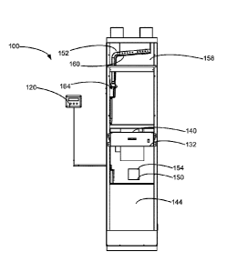
one or more valves that are controllable to vary the flow rate into the air
inlet 112, out of
the air outlet 116, into the fresh air inlet port 210, out of the exhaust air
outlet port 220,
into the bleed air conduit, into the oxygen concentrator 200, and/or into the
bypass
conduit 202. Accordingly, the flow rate between each of the inlets and outlets
may be
controllable to vary the amount of air that is conditioned by the oxygen
concentrator 200
before being output to the room 300.
[00116] Alternately, as exemplified in Figured 7 and 8, a bypass conduit
202 may
not be provided. In accordance with such an embodiment, all of the air
entering inlet
112 is delivered to the oxygen concentrator 200.
[00117] In some embodiments, the flow rates within the fan coil 100
may be
automatically controlled. For example, as exemplified in Figures 5-6, the fan
coil 100
may include an oxygen sensor 250. The oxygen sensor 250 may be operably
connected to the oxygen concentrator 200 and/or one or more valves (e.g., a
valve
controlling flow to the oxygen concentrator 200) such that the oxygen
concentrator 200
is actuated and/or air is flowed through the oxygen concentrator 200 and/or
the amount
of air provided to the oxygen concentration 200 is increased when the oxygen
sensor
250 detects an oxygen level (e.g., at a location in the volume or in the air
in the fan coil
- 23 -
Date recue / Date received 2021-11-08
upstream of the oxygen concentrator 200) below a predetermined level.
Similarly, when
the oxygen sensor 250 detects an oxygen level above a predetermined level, the
oxygen concentrator 200 may be deactivated and/or the flow of air through the
oxygen
concentrator 200 may be reduced or stopped. Accordingly, the air regulating
device 120
may use (and may optionally incorporate) the oxygen sensor 250 to control flow
rate
into the oxygen concentrator 200 from the input air that enters the air inlet
112 in order
to vary the amount of oxygen that is transferred from the exhaust air to the
input air.
[00118] In some embodiments, the fan coil 100 may include a filter
positioned
upstream of the oxygen concentrator 200. Positioning the filter upstream of
the oxygen
concentrator 200 may improve the operation of the oxygen concentrator 200 by
removing contaminates from the air prior to the air entering the oxygen
concentrator
200, thereby improving the quality of air and increasing the life cycle of the
oxygen
concentrator 200.
[00119] In some embodiments, as exemplified in Figures 3-4, the fan
coil 100 may
include a heat exchanger 154. The oxygen concentrator 200 may be connected in
flow
communication the air flow path 136 (e.g., with the fresh air) upstream of the
heat
exchanger 154. Connecting the oxygen concentrator 200 to the air flow path 136
upstream of the heat exchanger 154 allows the conditioned air to be heated or
cooled
along with the optional fresh air. Furthermore, the upstream connection may
more
efficiently transfer heat to air that will be delivered to the room 300,
without wasting
energy by heating air that is to be exhausted. Similarly, the nitrogen that is
removed
from the air in the oxygen concentrator 200 is not heated or cooled, thereby
saving
energy.
[00120] For example, as exemplified in Figures 3-4, the air flow path
136 may
include a temperature regulation zone 150 between an upstream first portion
144 of fan
coil air flow path 136, and a downstream second portion 152 of fan coil air
flow path
136. The temperature regulation zone 150 can include any heat exchanger 154
capable
of heating and/or cooling the air moving downstream across the temperature
regulation
zone 150. For example, the heat exchanger 154 can include any heating or
cooling
apparatus such as resistive heating elements, a natural gas burner, air
conditioning, or
-24 -
Date recue / Date received 2021-11-08
the like. In some embodiments, the air heating device 154 includes a heat
recovery
ventilator (HRV) unit or an energy recovery ventilator (ERV) unit that
receives heat, or
heat and humidity, from air that is to be exhausted for use, e.g., in treating
fresh air
introduced into the unit from the outside.
[00121] The oxygen concentrator 200 may be part of the HRV or ERV units.
[00122] In some embodiments, the oxygen enrichment apparatus 400 may
be a
stand-alone unit which only contains an oxygen concentrator 200. Alternately,
the
oxygen enrichment apparatus 400 may be a room air cleaner, a room air
purifier, a
room heater, a room air conditioner, a humidifier, a dehumidifier or a
combination of one
or more thereof which includes an oxygen concentrator 200. Such an oxygen
enrichment apparatus 400 may be built in or it may be portable.
[00123] As exemplified in Figure 9, the oxygen enrichment apparatus
400 may be
a portable unit that is positioned in a living space 300. The oxygen
enrichment
apparatus 400 may operate in the oxygen enrichment mode wherein, as described
previously with respect to fan coil 100, some or all of the air that enters
inlet 112 is
treated to produce an oxygen enriched air stream that is delivered to room 300
via
outlet 116. During the oxygen enrichment mode, nitrogen may be adsorbed on a
zeolite
material.
[00124] When sufficient nitrogen has been adsorbed, then the oxygen
enrichment
apparatus 400 may be operated in the regeneration mode and the nitrogen may be
purged via purge vent 224. The oxygen enrichment apparatus 400 may be operated
in
the regeneration mode when positioned in the room 300. In such a case, the
oxygen
enrichment apparatus 400 may be in communication with the exterior area 310 by
a
conduit, e.g., a flexible tube 402, that extends, e.g., through a wall or
window of the
room 300.
[00125] For example, the oxygen enrichment apparatus 400 may be
installed on a
wall or a window of room 300 using a wall mount and/or a window mount.
Mounting the
fan coil 100 to a window or wall allows a user to connect an optional fresh
air inlet port
210 to the location 310 exterior to the living space 300 via, e.g., a flexible
tube 404, that
- 25 -
Date recue / Date received 2021-11-08
extends, e.g., through a wall or window of the room 300. Similarly, the
exhaust air outlet
port 220 of the oxygen enrichment apparatus 400 may be connected to the
location 310
exterior to the living space 300 via flexible tube 402. This connection allows
a user to
run the oxygen enrichment apparatus 400 in both the oxygen enriching mode and
the
regeneration mode without the need to bring the fan coil 100 to the location
310.Accordingly, the oxygen enrichment apparatus 400 may automatically enter
the
regeneration mode when required. It will be appreciated that such an
embodiment may
be used with an oxygen concentrator 200 that continuously exhausts oxygen
reduced
air.
[00126] Alternately or in addition, the oxygen enrichment apparatus 400 may
be
transported (e.g., carried) to the exterior area 310 when the oxygen
enrichment
apparatus 400 is to be run in the regeneration mode. In other words, to purge
the
nitrogen that was adsorbed by the oxygen concentrator 200, a user may bring
the
oxygen enrichment apparatus 400 out of the living space 300 to release the
nitrogen. It
will be appreciated that, when in the regeneration mode, the nitrogen may be
purged
from the air outlet 116 or may be purged through a purge vent 224.
Multi-Unit Building HVAC System Using a Closed Loop Intermediary Heat Transfer
Fluid
[00127] In accordance with this aspect, an intermediary fluid is used
to transfer
heat between a high pressure riser stack 1120 and a fan coil in a unit 1020.
This aspect
may be used by itself or in combination with one or more aspects set out
herein. An
advantage of this aspect is that a limited amount of low pressure fluid
(optionally a
liquid) may be conveyed throughout a floor of a building such that high
pressure fluid
(the stack fluid 1122) is located only within the riser stack 1120 and
therefore there is
less risk of a leak of high pressure fluid, and, in case of a leak, the leak
may be located
at the riser stack 1120 at which location an appropriate drain and/or
containment
chamber may be provided to contain the leak.
[00128] Referring to Figure 10, an exemplary embodiment of a multi-
unit building
HVAC system is shown generally as 1000. The following is a general discussion
of
system 1000, which provides a basis for understanding several of the features
that are
discussed herein. As discussed subsequently, each of the features may be used
- 26 -
Date recue / Date received 2021-11-08
individually or in any particular combination or sub-combination in this or in
other
embodiments disclosed herein.
[00129] Embodiments described herein include an HVAC system 1000 for
use in a
building 1010. In accordance with this aspect, which may be used by itself or
in
combination with one or more other aspects, the HVAC system 1000 is used in
the
building 1010 that includes a plurality of units 1020 and at least one riser
stack 1120.
For example, each unit 1020 may be a condominium and the plurality of units
may form
a condominium block. Alternately, each unit may be an office having multiple
rooms or a
single large room. It will be appreciated that HVAC system 1000 may be used in
any
building wherein a single source of heating and/or cooling fluid is used to
provide
heating and/or cooling to multiple individual units.
[00130] A riser fluid 1122 that may be under high pressure is
circulated within a
riser stack 1120. Each riser stack 1120 operates with the riser fluid 1122
under pressure
such that the riser fluid 1122 is transferred up each riser stack 1120 to each
floor 1012
of the building 1010. The pressure in the riser stack will depend upon the
height of the
building, and therefore the height to which the riser fluid 1122 must be
raised. For
example, the pressure of the riser fluid 1122 may be at least 100 psi, 150
psi, 200 psi or
more.
[00131] It will be appreciated that the riser stack 1120 may be a
single riser stack
1120 or a plurality of riser stacks 1120. For example, a building may have a
single riser
stack 1120 which may be used only for heating (i.e., a heated riser fluid 1122
is
circulated in the riser stack 1120), only for cooling (i.e., a chilled riser
fluid 1122 is
circulated in the riser stack 1120) or both heating and cooling (e.g., a
heated riser fluid
1122 is circulated in the riser stack 1120 in the winter and a chilled riser
fluid 1122 is
circulated in the riser stack 1120). Therefore, it will be appreciated that
each riser 1120
may alternate between heating and cooling, depending on the seasonal use of
the
HVAC system 1000. Alternately, a building may have a plurality of riser stacks
1120.
For example, the building may have one riser stack 1120 for heating (hot riser
1124)
and one riser stack 1120 for cooling (cold riser 1126) or the building may
have a
plurality of hot risers 1124 and/or a plurality of cold risers 1126.
- 27 -
Date recue / Date received 202 1-1 1-08
[00132] During use, the riser fluid 1122 for the heating mode is
heated by a
heating device 1140 and the riser fluid for the cooling mode is cooled by a
cooling
device 1150. For example, the heating device 1140 may be a boiler or furnace
and the
cooling device 1150 may be an air conditioner.
[00133] The HVAC system 1000 includes a plurality of single unit HVAC
systems
1200 that are each in individual thermal communication with the riser stack(s)
120 via
one or more closed loop fluid flow paths 1260. An advantage of this design is
that the
high pressure riser stack(s) 120 may be isolated from the individual single
unit HVAC
systems 1200. Accordingly, heat transfer between the riser stack 1120 and a
single unit
may occur with a low pressure heat transfer system, thereby reducing the
likelihood of
damage to the unit 1020 and/or building 1010 as a result of leakage of the
single unit
HVAC system 1200. For example, the closed loop fluid flow path 1260 that
conveys
heat between the high pressure riser stack(s) 120 and the fan coil in a single
unit may
be at a low pressure and may also use a relatively small amount of fluid.
Accordingly, if
a leak were to occur in the closed loop system, then a limited amount of fluid
would be
released, which would be at a lower pressure.
[00134] Each riser stack 1120 is in thermal communication with one or
more single
unit HVAC systems 1200 on each floor 1012 of the building 1010. For example, a
single
riser (or a pair of hot riser 1124 and cold riser 1126) may be used to heat or
cool a
single unit 1020. Alternately, a single riser (or pair of hot riser 1124 and
cold riser 1126)
may be used to heat or cool a plurality of units 1020. If a plurality of riser
stacks 1120
(or a plurality of pairs of hot risers 1124 and cold risers 1126) are
provided, then they
may be distributed at different locations on a floor as is exemplified in
Figure 10.
[00135] Accordingly, each single unit HVAC system 1200 can be heated
and/or
cooled by the riser stack(s) 120 through the use of a plurality of heat
exchangers. For
example, as exemplified in Figure 12, the single unit HVAC system 1200 has a
first heat
exchanger 1220 thermally connecting the riser stack and the closed loop fluid
flow path
1260, and a second heat exchanger 1222 thermally connecting the closed loop
fluid
flow path 1260 to a fluid distribution system 1240 within the unit 1020. The
fluid
distribution system 1240 may also be referred to as the distribution flow path
1240. The
- 28 -
Date recue / Date received 202 1-1 1-08
closed loop fluid flow path 1260 extends between the first heat exchanger 1220
and the
second heat exchanger 1222. The closed loop fluid flow path 1260 may also be
referred
to as a sub-loop 1260. The first heat exchanger 1220 exchanges heat between
the riser
stack fluid 1122 and a closed loop fluid 1262 in the closed loop fluid flow
path 1260,
while the second heat exchanger 1222 exchanges heat between the closed loop
fluid
1262 and a distribution fluid 1242 of the fluid distribution system 1240. The
closed loop
fluid 1262 may also be referred to as a modulation fluid 1262 as it modulates
the
temperature of the distribution fluid 1242 via, e.g., one or more fan coils
100 provided in
the unit 1020. As exemplified in Figure 15, the portion of the closed loop
fluid flow path
1260 that travels within a fan coil 100 may be referred to as a modulation
fluid flow path
1320.
[00136] It will be appreciated that any heat exchanger may be used.
For example,
the heat exchanger may be a counter current indirect heat exchanger.
Alternately, the
first heat exchanger 1220 may be the closed loop fluid flow path 1260 wrapped
around
the riser stack 1120.
[00137] During use in a heating cycle, for example, the first heat
exchanger 1220
is used to pass heat from the riser stack 1120 to the closed loop fluid flow
path 1260
thereby heating the closed loop fluid 1262 to produce heated closed loop fluid
1262.
The second heat exchanger 1222 draws heat from the heated closed loop fluid
1262
and passes the heat to the distribution fluid 1242 in the distribution fluid
system 1240.
The heated distribution fluid 1242 is then exhausted into the unit 1020 to
heat the unit
1020. It will be appreciated that the same operation may be used to cool the
unit 1020,
using the cooled riser 1120.
[00138] The closed loop fluid 1262 may operate at a relatively low
pressure within
each unit 1020 in the building 1010 such that the higher pressure system of
the riser
stacks 1120 is isolated from the low pressure system within each unit 1020 in
the
building 1010. Operating the closed loop fluid 1262 at a low pressure may
reduce the
risk of leakage in the sub-loop 1260. If a leak does occur, the leak may expel
a relatively
small volume of the closed loop fluid 1262, thereby reducing damage to the
unit. For
- 29 -
Date recue / Date received 2021-11-08
example, the closed loop fluid 1262 may be at a pressure of up to 50 psi,
optionally up
to 30 psi or optionally in the range of about 5 to about 15 psi.
[00139] The closed loop fluid flow path 1260 may have a relatively low
volume of
closed loop fluid 1262. For example, the closed loop fluid flow path 1260 may
utilize 1-
200 L, optionally 2-100 L, or optionally 5- 30 L. Accordingly, in the event of
a leak, the
damage caused by the closed loop fluid 1262 may be minimized due to the low
volume
of fluid 1262 in the sub-loop 1260.
[00140] The closed loop fluid 1262 may be any fluid capable of
transferring heat
between the riser fluid 1122 and the distribution fluid 1242. For example, the
closed
loop fluid 1262 may be a liquid, and optionally may be water. It will be
appreciated that
the closed loop fluid may not be buffered the same way that the riser fluid
may be
buffered.
[00141] Similarly, the distribution fluid 1242 may be any fluid
capable of
transferring heat between the closed loop fluid 1262 and the unit 1020 of the
building
.. 1010. For example, the distribution fluid 1242 may be a gas, and optionally
may be air.
[00142] It will be appreciated that the closed loop fluid flow path
1260 may be any
size, shape, and/or material to distribute the closed loop fluid 1262
throughout the
closed loop flow path 1260. For example, the closed loop fluid flow path 1260
may
comprise or consist of a conduit 1264 having a wall thickness in the range of
about 0.01
to about 0.06 inches, optionally 0.02 to 0.04 inches. The conduit 1264 may be
made of
metal. The thin wall thickness and metal material may improve the thermal
communication between the closed loop fluid flow path 1260 and the heat
exchangers
1220, 1222 to transfer heat more efficiently between the riser fluid 1122 and
the closed
loop fluid 1262 and between the closed loop fluid 1262 and the distribution
fluid 1242.
[00143] Referring to Figure 11, as exemplified, the floor in the building
has a
plurality of units 1020. One or more riser stacks 1120 is thermally coupled to
single unit
HVAC systems 1200. It will be appreciated that one or more closed loop fluid
flow paths
1260 may thermally connect a single unit 1020 to one or more riser stacks 1120
and
each single unit HVAC systems 1200 may comprise one or more fan coils (or at
least a
- 30 -
Date recue / Date received 202 1-1 1-08
heat exchanger) that is thermally connected to the one or more closed loop
fluid flow
paths 1260.
[00144] As exemplified in Figure 11, each unit 1020 has its own
respective single
unit HVAC system 1200. Accordingly, for example, the first single unit HVAC
system
1200 provides temperature regulation to the first unit 1020a, the second
single unit
HVAC system 1200 provides temperature modulation to the second unit 1020b, and
so
on. Each unit 1020a, 1020b is schematically shown as a single room, although
each
unit may have any number of rooms.
[00145] In some embodiments, each unit 1020 may be thermally coupled
to its
own respective riser(s) 120. Alternately, or in addition, a plurality of units
1020 may
share one or more risers 1120. In other words, the riser stacks 1120 may be
exterior to
the unit 1020 with the closed loop fluid flow path 1260 providing thermal
communication
from the exterior riser stack 1120 to within the unit 1020. For example, as
exemplified in
Figure 11, there are six units 1020 a-f and four riser stacks 1120. Units
1020b and
1020e share the riser stacks 1120 with units 1020a and 1020d respectively,
while units
1020c and 1020f each have their own riser stacks 1120. Accordingly, the design
of the
building 1010 may be simplified since fewer riser stacks 1120 are needed to
provide
thermal energy (heating and/or cooling) to every unit 1020 on the floor 1012.
Reducing
the number of riser stacks 1120 may reduce the likelihood of leakage, while
also
simplifying construction of the building 1010. It will be appreciated that the
configuration
may vary depending on the floor layout of the units 1020 in the building 1010.
[00146] The single unit HVAC system 1200 may include more than one
heat
exchanger 1220 and more than one heat exchanger 1222. For example, if a unit
1020
has more than one room, then a heat exchanger (fan coil) may be provided for
each
room or as discussed subsequently, a heat exchanger (fan coil) may be provided
in a
wall that separates two rooms and the heat exchanger (fan coil) may heat
and/or cool
both rooms. Referring to Figure 13A, as exemplified, the single unit 1020
includes three
rooms 1022, 1024, 1026. Each room has its own respective heat exchanger for
thermal
communication with the sub-loop 1260, the sub-loop 1260 being in thermal
communication with one or more risers 1120. In other words, the first room
1022 has a
- 31 -
Date recue / Date received 2021-11-08
second heat exchanger 1222, the second room 1024 has a different second heat
exchanger 1222, and the third room has a further different second heat
exchanger
1222. The second heat exchanger 1222 provides temperature modulation to the
first
room 1022, the second heat exchanger 1222 provides temperature modulation to
the
second room 1024, and the second heat exchanger 1222 provides temperature
modulation to the third room 1026. Accordingly, as exemplified in Figure 13A,
the closed
loop fluid flow path 1260 extends between each of the second heat exchangers
1222
and the riser 1120.
[00147] It will be appreciated that closed loop fluid flow path 1260
may be a single
flow path that extends sequentially through each of the rooms 1022, 1024,
1026.
Alternately, the single unit HVAC system 1200 may include a plurality of
closed loop
fluid flow paths 1260. For example, there may be a plurality of heat
exchangers in a
single unit 1020, such as a heat exchanger for each room in the unit 1020.
Each heat
exchanger may be in thermal communication with the same closed loop fluid flow
path
1260 or may have its own respective closed loop fluid flow path 1260 in
thermal
communication with the riser stacks 1120. For example, the closed loop fluid
flow path
1260 may have one or more splitters to subdivide the closed loop fluid flow
path 1260
that extend to one or two of the rooms 1022, 1024, 1026 prior to returning to
the riser
stack 1120. For example, a single line may enter unit 1020a and then split
into three
lines, one which extends to second heat exchanger 1222 in room 1022, a second
that
extends to second heat exchanger 1222 in room 1024 and a third that extends to
second heat exchanger 1222 in room 1026. Downstream of the second heat
exchangers 1222, the three lines may merge to form a single line that returns
to the
riser stack 1120.
[00148] Alternately, each room need not have its own respective heat
exchanger.
For example, a single unit HVAC system 1200 may have a single fan coil 100 and
the
distribution flow path 1240 may comprise a ducting system that extends from
the single
fan coil 100 as is known in the art. Accordingly ducting for air (or a conduit
for a liquid)
may extend from the single fan coil 100 to each room in the unit 1020.
- 32 -
Date recue / Date received 2021-11-08
[00149] Alternately, a single unit HVAC system 1200 may have more
than one fan
coil 100 but fewer fan coils 100 than rooms in the unit. For example, as
exemplified in
Figure 13B, single unit HVAC system 1200 comprises only two fan coils 100a,
100b.
Accordingly, a fluid conduit 1228 (e.g., ducting for air), which is part of
the distribution
flow path 1240, extends between heat exchanger 1222 (fan coil 100b) and room
1026.
Accordingly, a single heat exchanger may be used to distribute the
distribution fluid
1242 to a plurality of rooms. While a single riser 1120 is exemplified, it
will be
appreciated that the same layout of heat exchangers may be used for a
plurality of
risers 1120 (e.g., separate hot and cool risers).
Leak Reduction and Detection for the Riser Stack
[00150] In accordance with this aspect, a riser stack 1120 is
positioned and/or
constructed to limit the extent of riser fluid 1122 leaking should the riser
stack 1120 leak
and/or the one or more leak detectors may be provided. This aspect may be used
by
itself or in combination with one or more aspects set out herein. An advantage
of this
aspect is that a riser stack 1120 may be provided interior a liner and/or in a
room with a
catch basin and a drain such that, should a leak occur, the leak may be
maintained.
[00151] For example, as exemplified in Figure 12, the one or more
riser stacks
1120 in the building may be provided interior of a liner conduit 1128. The
liner conduit
1128 may be in flow communication with a drain 1130, so that in the event of a
leak in
the riser stack 1120, the liner conduit 1128 may direct leaked fluid 1122 to
the drain
1130. Accordingly, damage to the building 1010 may be reduced if a leak
occurs. An
advantage of this design is that if there is a leak of the high pressure riser
fluid 1122, the
leak is contained within the liner conduit 1128 and directed out the drain
1130 to prevent
damage to the units 1020 in the building 1010. It will be appreciated that a
single drain
1130 may be provided at the bottom of the riser stack 1120. Alternately, a 130
drain
may be provided on each floor.
[00152] It will be appreciated that a drain 1130 may not be provided.
For example,
the liner may extend to the bottom (e.g., basement) of a building where the
heating/cooling source is located.
- 33 -
Date recue / Date received 202 1-1 1-08
[00153] Alternately, a liner 1128 may not be provided. Instead, each
floor may
have a catch basin surrounding the riser stack 1120 and the catch basin may
have a
drain 1130.
[00154] Alternately to the liner and or catch basin, the HVAC system
1000 may
have a riser leak detector 1132. The riser leak detector 1132 may be used to
issue a
signal that terminates flow in the riser stack 1120 upon a leak in the riser
stack 1120
being detected. In the event of a leak, the riser fluid 1122 may be shut off
rapidly to
prevent damage to the building 1010. It will be appreciated that any riser
leak detector
1132 may be used, including, but not limited to, a float switch, a
conductivity sensor,
and a capacitance leak detector. The riser leak detector 1132 may issue a
signal to,
e.g., a solenoid, which closes a valve thereby terminating flow in the riser
stack and/or
which shuts off a pump that circulates the riser fluid 1122. It will be
appreciated that
instead of, or in addition to, shutting off the flow of riser fluid 1122, the
riser leak
detector 1132 may issue a signal to warn a user that there is a leak.
[00155] Alternately or in addition, the HVAC system may have a closed loop
leak
detector 1266. The closed loop leak detector 1266 may be used to issue a
signal that
terminates flow in the closed loop fluid flow path 1260 upon a leak in the
closed loop
fluid flow path 1260 being detected (e.g., a valve 1268 may be shut, see for
example
Figure 12). It will be appreciated that any closed loop leak detector 1266 may
be used,
including, but not limited to, a float switch, a conductivity sensor, and a
capacitance leak
detector. The closed loop leak detector 1266 may issue a signal to, e.g., a
solenoid,
which closes a valve thereby terminating flow in the closed loop 1260 and/or
which
shuts off a pump that circulates the closed loop fluid 1262. It will be
appreciated that
instead of, or in addition to, shutting off the flow of closed loop fluid
1262, the closed
loop leak detector 1266 may issue a signal to warn a user that there is a
leak.
[00156] Alternately or in addition, the HVAC system 1200 may have a
closed loop
high pressure sensor. The closed loop high pressure sensor may issue a signal
that
terminates flow in the closed loop fluid flow path 1260 upon a high pressure
condition
being detected. A high pressure in the closed loop flow path 1260 may be
indicative of a
blockage in the closed loop fluid flow path 1260. Accordingly, the high
pressure sensor
-34 -
Date recue / Date received 202 1-1 1-08
may be used to provide an alert that there is a blockage and indicate that the
closed
loop fluid flow path 1260 needs maintenance. Providing early maintenance in
the event
of a blockage may prevent a leak from occurring, thereby preventing damage to
the
building 1010.
[00157] It will be appreciated that, at the riser stack 1120, a fluid which
leaks may
be the riser fluid 1122 or the closed loop fluid 1262. Due to the treatment of
riser stack
fluid 1122, riser stack fluid 1122 will typically have greater electrical
conductivity to the
closed loop fluid 1262.Accordingly, a capacitance leak detector may be used to
terminate the flow in the riser stack 1120 or the closed loop fluid flow path
1260
depending upon the capacitance of the fluid that leaks. For example, upon
occurrence
of a leak, the capacitance leak detector may issue a signal that terminates
flow in the
riser stack 1120 if the capacitance leak detector detects a fluid having a
capacitance
above a present capacitance that is indicative of the riser fluid 1122.
Similarly, the
capacitance leak detector may issue a signal that terminates flow in the
closed loop fluid
flow path 1260 if the capacitance leak detector detects a fluid having a
capacitance
below a present capacitance that is indicative of the closed loop fluid 1262.
In other
words, the capacitance leak detector may be used to identify which of the
closed loop
fluid flow path 1260 and riser stack 1120 has a leak, and once the leak source
is
identified, terminate flow in the identified fluid source.
Fan Coil
[00158] In accordance with this aspect, which may be used by itself or
in
combination with one or more other aspects, a fan coil may utilize a heat
exchanger
which operates at a lower pressure and therefore uses a thinner walled heat
exchanger.
An advantage of this design is that the fan coil may have a higher heat
transfer rate
.. between the closed loop fluid 1262 and the distribution fluid 1242.
[00159] As exemplified in Figure 12, the second heat exchanger 1222
may be
positioned within a fan coil 100. The second heat exchanger 1222 may be used
to
modulate the temperature of distribution fluid 1242 (e.g., air) received from
within the
unit 1020, using the modulation fluid (closed loop fluid) 262 that flows
through a
modulation fluid flow path 1320 (the portion of the closed loop fluid flow
path 1260 in fan
- 35 -
Date recue / Date received 202 1-1 1-08
coil 100). An advantage of this aspect is that the fan coil 100 may be in
thermal
communication with a low volume, low pressure temperature modulation fluid
1262
(e.g., the closed loop fluid), without directly fluidly communicating with the
higher
pressure riser stack 1120. Accordingly, in the event of a leak, the damage may
be
mitigated within the building 1010 because the leak is contained by the riser
stack 1120
or involves such a low volume of temperature modulation fluid 1262 that the
damage is
minimized. Additionally, due to the lower volume and lower pressure of the
modulation
fluid 1262, the conduit 1264 used to hold the modulation fluid 1262 may have a
smaller
diameter and a thinner wall, resulting in cheaper piping and more efficient
heat
exchange.
[00160] In accordance with this aspect, as exemplified in Figures 11-
18, the single
unit HVAC system 1200 has a fan coil 100 that includes the second heat
exchanger
1222. The second heat exchanger 1222 operates to exchange thermal energy
between
the modulation fluid 1262 in the modulation fluid flow path 1320 and the
distribution fluid
1242.
[00161] It will be appreciated that a fan coil 100 as referenced
herein may
comprise, or consist of, a second heat exchanger 1222 and a motor and fan
assembly
1340. Optionally, it may include one or more of a humidifier, an air filter,
and an oxygen
concentrator etc. as discussed subsequently. Optionally, the second heat
exchanger
1222 may be in fluid flow communication with air drawn from the exterior of
the building
and the fan coil 100 may include an air to air heat exchanger to heat/cool the
incoming
air with air exhausted to the outside.
[00162] As exemplified in Figures 14A and 14B, the fan coil 100 has an
inlet 1330
for receiving the distribution fluid 1242 (e.g., air) from a room and an
outlet 1332 for
delivering the distribution fluid 1242. The outlet 1332 delivers the
temperature
modulated air 1242 after the distribution fluid 1242 (i.e., air from the room)
has been
cooled or heated by the second heat exchanger 1222. The fan coil 100 includes
a first
motor and fan assembly 1340 in the distribution flow path 1240. The motor and
fan
assembly 1340 is used to draw air 1242 from the room into the inlet 1330
and/or
exhaust the temperature modulated air 1242 through the outlet 1332 back to the
room.
- 36 -
Date recue / Date received 202 1-1 1-08
[00163] The fan coil 100 may be designed to reduce the footprint of
the single unit
1020 HVAC system 1000 within the building. For example, the fan coil 100 may
be
sized to fit between two wall studs 1030 (which may be positioned a standard
distance
apart, such as 16 inches) in the building 10, as exemplified in Figures 14A
and 18. In
some embodiments, a front side 1302 of the fan coil 100 may have a width of
less than
about 16 inches.
Reversing Motor and Fan Assembly
[00164] In accordance with this aspect, which may be used by itself or
in
combination with one or more other aspects, a fan coil 100 may include a motor
and fan
assembly that may be operable to direct air in a first direction and
subsequently direct
air in a second opposite direction. An advantage of this aspect is that the
fan coil 100
may be used to recirculate air between the upper portion of a room and a lower
portion
of the room.
[00165] Optionally, as exemplified in Figures 14A-17, the unit air
distribution flow
path 1240 may have a lower port 1350 positioned to be adjacent a floor 1012 of
the
room and an upper port 1352 positioned to be adjacent a ceiling 1028 of the
room. In
some embodiments, the first motor and fan assembly 1340 may be a reversing
motor
and fan assembly that is operable in a first mode to direct air through the
upper port
1352 and is operable in a second mode to direct air through the lower port
1350.
Accordingly, in the first mode, the lower port 1350 functions as the inlet
1330 and the
upper port 1352 functions as the outlet 1332, while in the second mode, the
upper port
1352 functions as the inlet 1330 and the lower port 1350 functions as the
outlet 1332.
[00166] Another advantage of this design is that the direction of air
1242
exhausted by the fan coil 100 may be adapted to account for seasonal changes
in
temperature. For example, the fan coil 100 may operate in a summer mode,
whereby
colder distribution fluid 1242 is taken from the lower port 1350 and exhausted
from the
upper port 1352. During summer, the air temperature at the floor 1012 is
typically cooler
than the air temperature at the ceiling 1028. Accordingly, by moving the
cooler air from
the lower port 1350 to the upper port 1352, the change in temperature between
the
distribution fluid 1242 and the modulation fluid 1262 is reduced, thereby
resulting in a
- 37 -
Date recue / Date received 2021-11-08
more efficient heat transfer between the modulation fluid 1262 and the
distribution fluid
1242. Similarly, the fan coil 100 may operate in a winter mode, whereby hot
air
proximate the ceiling 1028 is returned through the upper port 1352 and
exhausted
through the lower port 1350. In other words, the gradation in temperature
within the
vertical height of the room may be utilized to exchange heat more efficiently
between
the distribution fluid 1242 and the sub-loop 1260.
[00167] For example, the fan coil 100 may have one or more filters for
filtering the
distribution fluid 1242 on the way into the fan coil 100 and/or out of the fan
coil 100. As
exemplified in Figures 15 and 16, the fan coil 100 has a first filter 1360 for
filtering air
entering the lower port 1350 and a second filter 1360 for filtering air
exiting the upper
port 1352. The filter 1360 may be any filter capable of treating the
distribution fluid 1242.
For example, the filter 1360 may be a cyclone and/or a physical filter media.
In some
embodiments, the first filter 1360 may be used in a first mode wherein air
enters via a
port located at that filter, while the second filter 1360 may be used in a
second mode
wherein air enters via a port located at that filter. A bypass valve may be
used to alter
the distribution fluid flow path 1240 such that one of the filters is bypassed
in one or
both modes.
[00168] The system may include a filter indicator that provides
indication of the
cleanliness of the filter 1360. For example, there may be a pressure sensor or
a colour
sensor, or both, that indicate when the filter 1360 is dirty and needs to be
cleaned. The
dirt indicator may send a signal to an electronic device, e.g., a control
module wired to
the system or a smart phone) indicating that the filter 1360 needs to be
cleaned.
[00169] Alternately, or in addition, the fan coil 100 may include
treatment devices
for treating the distribution air. For example, the fan coil 100 may include a
humidifier
and/or a dehumidifier. The fan coil 100 may also operate to exchange the
distribution
fluid 1242 with a location exterior to the unit 1020. For example, the supply
of
distribution fluid 1242 may come from a fresh air source, such as exterior to
the building
1010. The incoming air may be treated by one or more filters 1360 to improve
the
quality of the air entering the unit 1020. Alternately, or in addition the
incoming air may
.. be treated by a chemical conversion process to reduce potentially harmful
contaminants
- 38 -
Date recue / Date received 202 1-1 1-08
from the incoming air. For example, the chemical conversion process may break
down
ozone, carbon monoxide, nitrous oxides, sulfur oxides, and/or other harmful
compounds
from the incoming air to improve the air quality of air entering the unit
1020.
[00170] The exhaust air may also be treated to recover beneficial
components of
the exhaust air, such as oxygen and/or heat. For example, the single unit HVAC
system
1200 may have an exhaust heat exchanger for recovering heat from air exiting
the unit
1020 and transferring the recovered heat to the incoming fresh air. The HVAC
system
1200 may have an oxygen concentrator. Similar to the heat recovery, oxygen
from the
exhaust air may be recovered and passed to the fresh incoming air to increase
the
oxygen concentration of the incoming air. In other words, the heat and/or
oxygen from
exhaust air leaving the HVAC system 1200 may be recovered and passed to the
incoming air.
Fluid Detection for the Fan Coil
[00171] In accordance with this aspect, which may be used by itself or
in
combination with one or more other aspects, a catch basin and optional drain
may be
provided to collect closed loop fluid 1262 that may leak and/or condensate
that may
build up in the fan coil. Alternately or in addition, one or more leak
detectors may be
provided for the fan coil 100.
[00172] As exemplified in Figure 15, the fan coil 100 may have a catch
basin 1370
for catching condensate from the heat exchanger 1222. The catch basin 1370 may
be in
flow communication with a drain such that collected condensate from the heat
exchanger 1222 is removed from the fan coil 100 through the drain. The catch
basin
1370 may include an overflow basin 1372 with a water sensor 1374 for shutting
off the
fan coil 100 in the event of excessive water buildup.
[00173] Optionally, the condensate may be used for cleaning any component
of
the fan coil 100, including, but not limited to the heat exchanger 1222 and/or
the filter
1360. The filter 1360 may include a disposable element or a reusable element.
For
example, the filter 1360 may be washable. In some embodiments, the condensate
caught by the catch basin 1370 may be used to automatically wash the filter
1360. The
- 39 -
Date recue / Date received 2021-11-08
condensate used for washing the filter 1360 may then be purged from the HVAC
system
1200 through the drain. In other words, the filter 1360 may be self-cleaning.
Fan Coil with a Plurality of Motor and Fan Assemblies
[00174] In accordance with this aspect, which may be used by itself or
in
combination with one or more other aspects, the fan coil 100 has a plurality
of motor
and fan assemblies. For example, in at least one mode, two or more motor and
fan
assemblies may be operated concurrently. An advantage of using two motor and
fan
assemblies that operate concurrently is that the power required by each motor
and fan
assembly to move the distribution fluid 1242 through the fan coil 100 may be
reduced
and Reducing the power of the noise of the fan coil 100 may be reduced.
[00175] Alternately, or in addition, each motor and fan assembly may
direct air in
a different direction through the fan coil 100. For example, as exemplified in
Figure 15,
the fan coil 100 may further have a second motor and fan assembly 1342. The
first
motor and fan assembly 1340 may be operable to direct air through the upper
port 1352
such that the lower port 1350 functions as the inlet 1330 and the upper port
1352
functions as the outlet 1332 and the second motor and fan assembly 1342 may be
operable to direct air 1242 through the lower port 1350 such that the upper
port 1352
functions as the inlet 1330 and the lower port 1350 function as the outlet
1332.
[00176] Optionally, at least one of the first motor and fan assembly
1340 and the
second motor and fan assembly 1342 may be a reversing fan. In other words, the
direction of distribution fluid flow 1242 induced by one or both of the first
and second
motor and fan assemblies 1340, 1342 may be switched. Accordingly, when one of
the
motor and fan assemblies 1340, 1342 is reversed, the first and second motor
and fan
assemblies 1340, 1342 may be operable concurrently to direct air 1242 through
one of
the upper and lower ports 1350, 1352. An advantage of this design is that,
when the
motor and fan assemblies 1340, 1342 are operating to direct air 1242 in the
same
direction, the power required to operate each motor and fan assembly 1340,
1342 may
be reduced, while maintaining the same air flow rate and air volume in the fan
coil 100.
In other words, the airflow through each motor and fan assembly 1340, 1342 is
reduced,
without impacting the overall flowrate through the fan coil 100. Reducing the
power of
-40 -
Date recue / Date received 2021-11-08
each of the motor and fan assemblies 1340, 1342 may reduce the noise
associated with
the fan coil 100. For example, the fan coil 100 may operate in the range of 15-
25 dB,
optionally 15-20 dB, or optionally 14-18 dB.
[00177] It will be appreciated that, in some embodiments, both of the
first and
second motor and fan assemblies 1340, 1342 may be reversible. Accordingly, the
first
motor and fan assembly 1340 may be operable in a first mode to direct air 1242
through
the upper port 1352 and a second mode to direct air through the lower port
1350.
Similarly, the second motor and fan assembly 1342 may be operable in a first
mode to
direct air 1242 through the lower port 1350 and a second mode to direct air
1242
through the upper port 1352. Each of the first and second fan and motor
assemblies
1340, 1342 may be concurrently operable in each mode such that the direction
of flow
of the distribution fluid 1242 is the same for each of the first mode and the
second
mode.
Fan Coil Between Rooms
[00178] In accordance with this aspect, which may be used by itself or in
combination with one or more other aspects, the single unit HVAC system 1200
may
include a fan coil 100 positioned in a wall 1032 between a first room 1022 and
an
adjacent second room 1024. An advantage of this aspect is that a single fan
coil 100
may directly moderate the temperature in two rooms without the need of HVAC
ducting.
Additionally, the temperature of each room may be varied by adjusting the flow
from the
fan coil into each room. In other words, the temperature of adjacent rooms may
be
controlled such that the temperature is different in each room.
[00179] In accordance with this aspect, as exemplified in Figures 17
and 18, the
fan coil 100 is positioned in the wall 1032 between the first room 1022 and
the second
room 1024. As shown, the fan coil 100 is optionally positioned between two
studs 1030
in the wall. It will be appreciated that the studs may be a standard distance
apart (e.g.,
16 inches). The fan coil may have an outer casing that forms part of the wall
of one or
both rooms. Optionally, the fan coil 100 is positioned behind the drywall that
forms the
walls of the rooms.
-41 -
Date recue / Date received 2021-11-08
[00180] Each room has a respective air return 1330 and air outlet 1332
from the
fan coil. The fan coil 100 is in flow communication with the air return 1330
and the air
outlet 1332 of each room 1022, 1024. Accordingly, distribution air 1242 may
enter the
fan coil 100 from one or both rooms 1022, 1024 through the air returns 1330
and may
be exhausted to one or both rooms 1022, 1024 through the air outlets 1332.
[00181] One or more adjustable dampers 1380 may be used to control the
distribution fluid 1242 which is exhausted to one or both of the rooms 1022,
1024. The
dampers may be any design which reduces the flow of air through an air outlet
1332,
such as an adjustable exit port. The damper may be manually or electronically
operated, such as by a temperature sensor 1382, which senses the temperature
in a
room. It will be appreciated that the temperature sensor 1382 may be
positioned at any
location in a room. A user may set a first desired temperature for room 1022
and a
different second desired temperature for room 1024. Sensors 1382 may send a
signal
to the damper 1380 for the room, which opens or closes the damper 1380 thereby
adjusting the amount of heated or cooled distribution air 1242 that enters the
room.
[00182] In another operating mode, each room may be set to the same
desired
temperature, but the amount of heating or cooling required by each room to
achieve the
common desired temperature may vary. For example, one room may be exposed to
sunshine, have electronic equipment that generates heat, or it may be the
kitchen. In
such a case, Sensors may open and close a damper to vary the heated/cooled air
entering that particular room to enable each of the rooms to achieve the
desired
temperature. Accordingly, for example, if room 1022 achieves the common
desired
temperature before room 1024, the air flow to room 1022 may be reduced or
eliminated
and therefore more or all of the heated/cooled distribution air 1242 may enter
room
1024 until room 1024 also achieves the desired temperature.
[00183] It will be appreciated that each room, or only some of the
rooms, may
have a temperature sensor 1382.
[00184] It will also be appreciated that each sensor 1382 may be part
of a
thermostat (i.e., a room may have its own thermostat) such that a user may set
the
temperature for a particular room by using the sensor 1382.
-42 -
Date recue / Date received 2021-11-08
[00185] Alternately, the unit 1020 may have its own central unit
thermostat. The
first temperature sensor 1382 and the second temperature sensor 1382 may be in
communication with the unit thermostat. Therefore, the unit thermostat may be
used to
set a desired temperature and one or more rooms may be provided with a
temperature
sensor 1382 that may be used to control the temperature of the room in which
the
sensor is located. An advantage of this design is that the accuracy of
temperature
measurement in each room may be improved, thereby more easily allowing for the
desired room temperature to be maintained.
[00186] The building 1010 may include a master thermostat that is in
communication with each unit thermostat in all of the units 1020 in the
building 1010. In
other words, the unit thermostat may be used to control the single unit HVAC
system
1200 and the master thermostat may be used to control the HVAC system 1000.
[00187] Accordingly, as exemplified, the first room 1022 may have a
first room air
distribution flow path 1240 extending between the lower port 1350 and the
upper port
1352 and the second room 1024 may have a second room air distribution flow
path
1240 extending between the lower port 1350 and the upper port 1352. As
exemplified in
Figure 17, the air outlet 1332 of the first room 1022 has a first adjustable
damper 1380
and a first temperature sensor 1382 and the air outlet 1332 of the second room
1024
has a second adjustable damper 1380 and a second temperature sensor 1382. The
first
damper 1380 is adjustable based on a signal from the first temperature sensor
1382
and the second damper 1380 is adjustable based on a signal from the second
temperature sensor 1382. The first and second adjustable dampers 1380 may be
used
to control the relative amount of the distribution fluid 1242 introduced into
each of the
first and second rooms 1022, 1024. For example, the first and second
adjustable
dampers 1380 may be used to control how much of the volume of the distribution
fluid
1242 is exhausted to each room. For example, 70% of the distribution fluid
1242 may go
to the first room 1022 while 30% of the distribution fluid 1242 may go to the
second
room 1024.
[00188] An advantage of this design is that the temperature of each
room may be
varied independently of the other room. For example, if the first room 1022 is
exposed
-43 -
Date recue / Date received 2021-11-08
to sun throughout the day, the first temperature sensor 1382 may read a first
room
temperature that is higher than a second room temperature measured by the
second
temperature sensor 1382. Accordingly, when in the heating cycle, a higher
percentage
of the distribution fluid 1242 may be exhausted to the second room 1024, to
maintain
the first room temperature and second room temperature at their desired
values. In
other words, since the sun has already provided heat to the first room 1022,
less heated
distribution fluid 1242 is required to maintain the first room temperature at
the desired
temperature, so the adjustable dampers 1380 may be used to reduce the volume
of
heated distribution fluid 1242 to the first room 1022 and to increase the
volume of
heated distribution fluid 1242 to the second room 1024. Similarly, in the
cooling cycle,
the room exposed to more sun may need additional cooled distribution fluid
1242 to
maintain the desired temperature. Accordingly, for example, 90% of the cooled
distribution fluid 1242 may be exhausted to the room exposed to the sun with
only 10%
of the cooled distribution fluid 1242 exhausted to the other room.
[00189] As described previously, the first motor and fan assembly 1340 may
be
reversible to operate the fan coil 100 in a first mode and a second mode,
whereby the
inlet 1330 and outlet 1332 of the fan coil 100 are reversed. The first motor
and fan
assembly 1340 may be used to move the distribution fluid 1242 along each of
the first
and second air flow distribution paths 1240. In some embodiments, the first
motor and
fan assembly 1340 and the second motor and fan assembly 1342 may be reversible
to
operate the fan coil 100 in the first mode and the second mode. In such
embodiments,
each of the first motor and fan assembly 1340 and the second motor and fan
assembly
1342 may be used to draw air from the inlets 1330 and expel air through the
outlets
1332 into each of the first and second rooms 1022, 1024.
Moveable Fan Coil
[00190] In accordance with this aspect, which may be used by itself or
in
combination with one or more other aspects, the single unit HVAC system 1200
has a
movable fan coil 100 such that at least a portion of the fan coil 100 is
movably mounted
within the air distribution flow path 1240. An advantage of this aspect is
that the exterior
casing of the fan coil need not be part of a wall of a room. Instead, the fan
coil may be
-44 -
Date recue / Date received 2021-11-08
behind drywall. The movable portion of the fan coil 100 may be moved to a
location that
enables maintenance to be performed on the fan coil 100, such as near the air
return
1330 or air outlet 1332.
[00191] In accordance with this aspect, in some embodiments, at least
a portion of
the fan coil 100 is movable in the air distribution flow path 1240 to a
position in which
the fan coil 100 is located at one of the air return 1330 and the air outlet
1332. As
exemplified in Figure 17, in some embodiments, the only access to the fan coil
100
through the wall 1032 is through the air return 1330 and the air outlet 1332.
Accordingly,
the movable portion of the fan coil 100 may be moved to one of the air return
1330 and
the air outlet 1332, thereby providing access to the fan coil 100 through the
wall 1032.
In the event a part of the fan coil requires routine maintenance or
replacement, the fan
coil 100 or the part of the fan coil 100 may be moved to the accessible air
return 1330 or
air outlet 1332 so that the interior of the fan coil 100 may be more easily
accessed.
[00192] It will be appreciated that any component of the fan coil 100
may form a
.. part of the movable portion of the fan coil 100. For example, the movable
portion may
include, but is not limited to, the second heat exchanger 1222, the catch
basin 1370, the
filter 1360, the motor and fan assembly 1340, and/or one or more sensors.
[00193] The movable portion of the fan coil 100 may be moved through
ducting
that extends from the air return 1330 to the fan coil 100 and from the fan
coil 100 to the
air outlet 1332. An advantage of this design is that the ducting may be clear
of
obstructions and provide a path in the wall 1032 for the movable portion to
move without
interfering with other components of the unit 1020 and/or HVAC system 1200.
[00194] It will be appreciated that the fan coil 100 may comprise or
consist only of
a second heat exchanger 1222, an optional catch basin 1370 and the motor and
fan
assembly 1340. If the second heat exchanger 1222 is connected to a low
pressure
closed loop 1260 and the fan coil 100 is used to moderate the temperature of
only one
or two rooms, then the fan coil 100 may be relatively small and able to fit
between
standardly positioned wall studs and may be moveable upwardly or downwardly
therein
such as by a motor that drives the fan coil 100 or a part thereof up and down
a track
within the air distribution flow path 1240 (in this case the volume between
the two
-45 -
Date recue / Date received 2021-11-08
studs). Any drive means known in the arts may be used. It will be appreciated
that since
the closed loop fluid flow path 1260uses a low pressure fluid, the conduit may
be
flexible such that the fan coil 100 may be raised or lowered without
disconnecting the
second heat exchanger 1222 from the closed loop fluid flow path 1260.
Single Unit HVAC System with Plurality of Heat Exchangers
[00195] In accordance with this aspect, which may be used by itself or
in
combination with one or more other aspects, the single unit HVAC system 1200
may
have a plurality of fan coils 1300 each of which is connected to the closed
loop fluid flow
path 1260. For example, a room 1022 may have a first fan coil 100 (e.g., a
second heat
exchanger 1222) to modulate the temperature of the room 1022 and the room 1024
may have a second fan coil (e.g., a second heat exchanger 1222) to modulate
the
temperature of the room 1024. An advantage of this aspect is that the
temperature of
each room may be controlled independently of the other room. Another advantage
is
that the heat exchanger for a particular room may be turned off when not
needed,
thereby saving energy. Furthermore, the temperature of each room is not
reliant upon a
single temperature sensor located in another room. Accordingly, each room may
be
more easily maintained at a desired room temperature. Further, as each fan
coil
provides heating or cooling for less than the entire unit (e.g., a single
room) the fan coil
100 may be smaller. It will be appreciated that each or all of the fan coils
may include
any one or more of the features that are discussed with respect to Figures 1-
9.
Alternately, one or more of the fan coils may consist essentially of or
consist of a heat
exchanger and a motor and fan assembly.
[00196] In accordance with this aspect, the single unit HVAC system
1200 has a
first fan coil 1300a, a second fan coil 1300b, and a third fan coil 1030c, as
exemplified in
Figure 13. The first fan coil 1300a is in the first room 1022, the second fan
coil 1300b is
in the second room 1024, and the third fan coil 1300c is in the third room
1026. Each
fan coil 100 has its own respective heat exchanger in thermal communication
with the
sub-loop 1260 to exchange thermal energy with the sub-loop 1260. An advantage
of
this design is that the fan coils 1300 may operate at a relatively lower air
flow rate since
the movement of air in the unit 1020 is shared amongst a plurality of fan
coils 1300.
-46 -
Date recue / Date received 2021-11-08
Operating the fan coils 1300 at a lower flow rate results in decreased noise
in the unit
1020 and conserved energy in the HVAC system 1000.
[00197] As exemplified in Figure 13A, the first fan coil 1130a
includes the second
heat exchanger 1222, the second fan coil 1130b includes a second heat
exchanger
1222, and the third fan coil 1130c includes a second heat exchanger 1222. Each
heat
exchanger includes a modulation fluid flow path 1320 and a room air
distribution flow
path 1240. The air distribution flow path 1240 has an inlet 1330 for receiving
air 1242
and an air outlet 1332 for delivering temperature modulated air 1242 to the
respective
room. Each fan coil 100 further includes a motor and fan assembly 1340
provided in the
room air distribution flow path 1240 for facilitating flow of the distribution
fluid 1242 in
the flow path 1240. Each room may have a corresponding temperature sensor 1382
operable to monitor a temperature of the room. Each fan coil 100 may include
an
adjustable damper 1380 that is adjustable based on a signal from the
temperature
sensor 1382 as discussed previously.
[00198] During operation, the sub-loop 1260 provides the closed loop fluid
1262 to
each heat exchanger. The closed loop fluid 1262 passes through each modulation
fluid
flow path 1320 in each heat exchanger, exchanging thermal energy with the heat
exchanger. The heat exchanger then exchanges the thermal energy from the
closed
loop fluid 1262 to the distribution fluid 1242 in the room air distribution
flow path 1240.
The distribution fluid 1242 is then exhausted from the fan coil 100 into the
room. The
amount of distribution fluid 1242 exhausted from the fan coil 100 may be
determined by
the temperature sensor 1382.
[00199] The temperature of the room may be modulated by altering the
volume of
distribution fluid 1242 exhausted by the fan coil 100 using the adjustable
damper 1380
as discussed previously. Once the temperature of the room is measured by the
temperature sensor 1382, a signal is sent to the adjustable damper 1380 to
adjust the
damper 1380 to control the amount of distribution fluid 1242 exhausted from
the air
outlet 1332.
[00200] In some embodiments, the flow of closed loop fluid 1262 in the
modulation
fluid flow path 1320 may be adjustable based on a signal from the temperature
sensor
-47 -
Date recue / Date received 2021-11-08
1382. For example, as exemplified in Figure 13A, closed loop fluid flow path
1260
includes a sub, sub loop flow path 1270 which connects the second heat
exchanger
1222 in flow communication with the fub loop fluid 1262 in closed loop fluid
flow path
1260. A valve 1272 is provided in sub loop flow path 1270 to adjust (e.g.,
reduce or
terminate) the flow in a sub loop flow path 1270. Alternately, as exemplified
in Figure
13B, the closed loop fluid flow path 1260 may extend sequentially through one
or more
second heat exchangers 1222 and a by-pass line 1276 is provided to enable some
or all
of the closed loop fluid 1262 to by-pass a second heat exchanger 1222. A valve
1272
may be used to adjust (e.g., reduce or terminate) the flow in the by-pass line
1276. For
.. example, if the riser stack 1120 is in heating mode and the temperature
sensor 1382
measures that the room temperature is too hot, the amount of closed loop fluid
1262
that enters the modulation fluid flow path 1320 may be reduced by
automatically
adjusting the valve 1272 based on the temperature sensor signal.
[00201] Accordingly, the temperature of each room may be modulated by
the
temperature sensor 1382 sending a signal to the adjustable damper 1380 and/or
the
modulation fluid flow path valve 1272 to adjust the amount of distribution
fluid 1242 that
is exhausted to the room and/or adjust the amount of modulation fluid 1262
that enters
the modulation fluid flow path 1320.
Heat Retaining Member
[00202] In accordance with this aspect, which may be used by itself or in
combination with one or more other aspects, the HVAC system 1000 or 1200 may
include one or more heat exchangers in thermal communication with a heat
retaining
member. The heat retaining member is in thermal communication with the
modulation
fluid flow path 1320 such that the heat retaining member may exchange thermal
energy
with the modulation fluid 1262. An advantage of this aspect is that the heat
retaining
member may store a large amount of thermal energy that dissipates slowly,
thereby
retaining the thermal energy within the HVAC system. Accordingly, the
distribution fluid
1242 may be heated or cooled more rapidly to facilitate a faster temperature
modulation
response or an alternate heat source, such as a furnace may not be required
and may
have a lower heating demand. Another advantage is that thermal energy may be
stored
-48 -
Date recue / Date received 202 1-1 1-08
in the heat retaining member to maintain the modulation fluid 1262 at the
proper
temperature with increased efficiency. Another advantage is that the heat
retaining
member may be in communication with a renewable energy source, such as a solar-
powered source, to provide a more sustainable energy source for heating the
building.
[00203] In accordance with this aspect, the HVAC system 1000 or 1200
includes
one or more heat retaining members 1400 in thermal communication with one or
more
of the heat exchangers in the HVAC system 1000, 1200. For example, as
exemplified in
Figure 16, the heat retaining member 1400 may have a fluid flow path 1402 that
is in
thermal communication with the heat retaining member 1400, e.g., it may extend
through the heat retaining member 1400 and form part of the modulation fluid
flow path
1320, or it may extend around the heat retaining member 1400. The fan coil may
include a heat exchanger 1222 as exemplified in Figure 15 which is an
interface
between the closed loop fluid 1262 and the distribution fluid 1242.
Accordingly, the heat
retaining member 1400 may be in thermal communication with the distribution
fluid 1242
through the heat exchanger. It will be appreciated that, in an alternate
embodiment, the
fluid flow path 1402 may be a separate flow loop from the closed loop flow
path 1260.
For example, the closed loop flow path 1260 may flow between the riser stack
and the
heat exchanger 1222. A separate flow loop 1402 may flow between the heat
retaining
member 400 and the heat exchanger 1222.
[00204] As exemplified in Figure 16, the single unit HVAC system 1200 may
include a plurality of heat retaining members 1400. The first heat retaining
member
1400 is in thermal communication with the hot riser 1124 and the second heat
retaining
member 1400 is in thermal communication with the cold riser 1126. Accordingly,
the first
heat retaining member 1400 is heated by the hot riser 1124 and the second heat
retaining member 1400 is cooled by the cold riser 1126. It will be appreciated
that, when
there is a single riser that alternates with heating and cooling fluid, there
may be a
single heat retaining member 1400 in thermal communication with the riser
1120.
[00205] During operation, for example, to heat the unit 1020, the
modulation fluid
1262 flows through the heat retaining member 1400 and draws thermal energy
from the
heat retaining member 1400. The modulation fluid 1262 then exchanges the
thermal
-49 -
Date recue / Date received 202 1-1 1-08
energy to the distribution fluid 1242 through the heat exchanger 1222, thereby
heating
the air 1242.
[00206] It will be appreciated that the closed loop fluid flow path
may continue to
circulate closed loop fluid while the fan coil is not in use to thereby pre-
heat or pre-cool
the heat retaining member 1400.
[00207] Alternately, or in addition, as exemplified in Figure 19, the
heat retaining
member 1400 may be in thermal communication with an external heating or
cooling
source 1410, such as a solar-powered heating source 1410 (e.g., solar heated
panels).
The solar energy from the sun 1420 may be used to supplement the heating of
the
building 1010 by thermally charging the heat retaining member 1400. A
modulation fluid
1462 may flow between the solar-powered source and the heat exchanger 1222
such
that the modulation fluid may thermally exchange the thermal energy from the
thermally
charged heat retaining member 1400 with the distribution fluid 1242 to heat
the unit
1020. Similarly, the heating or cooling source 1410 may be used to provide
cooling to
the heat retaining member 1400 to remove thermal energy from the heat
retaining
member 1400 (e.g., an external air conditioner). The cooled heat retaining
member
1400 may then be used to remove thermal energy from the modulation fluid 1462,
thereby cooling the modulation fluid 1462. The cooled modulation fluid 1462
may then
thermally exchange energy with the distribution fluid 1242 to cool the unit
1020.
[00208] The heat retaining member 1400 may be encased in an insulating
material, such that the only thermal energy transfer from the heat retaining
member
1400 to the distribution fluid 1262 occurs through the heat exchanger 1222.
[00209] It will be appreciated that the fan coil 100 may comprise two
heat
exchangers, one that is part of a loop including the riser stack and a second
that is part
of a loop including the heating or cooling source 1410.
[00210] It will also be appreciated that, in the embodiment of Figure
19, the heat
exchanger may also be in thermal communication with the riser stack as
discussed
herein.
- 50 -
Date recue / Date received 202 1-1 1-08
[00211] It will also be appreciated that the heat retaining member
1400 may be
provided at any location in a flow loop.
[00212] It will be appreciated that the heat retaining member 1400 may
be any
device and/or material capable of storing thermal energy. For example, the
heat
retaining member 1400 may be a solid material. In some embodiments, the heat
retaining member 1400 may be stone, optionally granite, or metal, optionally
aluminum.
[00213] The heat retaining member 1400 may be directly heated by, for
example,
the solar-powered energy source 1410, or may be indirectly heated. For
example, a
lens 1410 may be used to direct sunlight onto the heat retaining member 1400
to
thermally charge the heat retaining member, thereby directly heating the heat
retaining
member 1400. The lens may indirectly heat the heat retaining member 1400 by
heating
a conductive material that passes through the heat retaining member 1400 to
thermally
charge the heat retaining member 1400.
[00214] To cool the heat retaining member 1400, an adsorption cycle
air
conditioner may be used. For example, the solar energy stored in the heat
retaining
member 1400 may be used to power an adsorption cycle. The adsorption cycle may
use, for example, ammonia or lithium bromide. An advantage of this design is
that rare
earth metals are not needed for the cooling cycle. When using an adsorption
cycle with
ammonia, there may be an ammonia sensor for detecting the presence of ammonia.
If
ammonia is detected, a vacuum jar may be used to suck the ammonia into the
storage
device. The ammonia cycle may be isolated from the sub-loop 1260 to protect
the
occupants of the building 1010 in the event of a leak.
[00215] It will be appreciated that the heat retaining member 1400 may
be part of
the closed loop fluid flow path 1260 or part of a separate flow path 1460. For
example,
in the embodiment of Figure 16, another closed loop may deliver heated or
cooled fluid
to the heat retaining member 1400. Alternately, as exemplified in Figure 19,
the heat
retaining member 1400 may have its own closed loop fluid flow path 1460 that
extends
to the second heat exchanger 1222. Such an embodiment may be used if the heat
retaining member 1400 is exterior unit 1020 and optionally exterior to the
building 1010.
- 51 -
Date recue / Date received 202 1-1 1-08
[00216] While the above description describes features of example
embodiments,
it will be appreciated that some features and/or functions of the described
embodiments
are susceptible to modification without departing from the spirit and
principles of
operation of the described embodiments. For example, the various
characteristics which
are described by means of the represented embodiments or examples may be
selectively combined with each other. Accordingly, what has been described
above is
intended to be illustrative of the claimed concept and non-limiting. It will
be understood
by persons skilled in the art that other variants and modifications may be
made without
departing from the scope of the invention as defined in the claims appended
hereto. The
scope of the claims should not be limited by the preferred embodiments and
examples,
but should be given the broadest interpretation consistent with the
description as a
whole.
- 52 -
Date recue / Date received 202 1-1 1-08
CLAUSE SET A:
1. A fan coil comprising:
(a) a heat exchanger comprising a modulation fluid flow path and a unit air
distribution flow path, the unit air distribution flow path has an inlet for
receiving
air from a room and an outlet for delivering temperature modulated air,
wherein
the modulation fluid flow path is operable to receive a fluid that is at a
pressure of
up to 50 psi; and,
(b) a first motor and fan assembly in the unit air distribution flow path.
2. The fan coil of clause 1 wherein the modulation fluid flow path is operable
to receive
a fluid that is at a pressure of up to 30 psi.
3. The fan coil of clause 1 wherein the modulation fluid flow path comprises a
conduit
having a wall thickness of 0.01 to 0.06 inches.
4. The fan coil of clause 3 wherein the conduit has a wall thickness of 0.02
to 0.04
inches.
5. The fan coil of clause 3 wherein the conduit is metal.
6. The fan coil of clause 1 wherein the modulation fluid flow path further
comprises a
low pressure closed loop flow path that is connected in thermal communication
with
a high pressure riser stack of a multi-floor building.
7. The fan coil of clause 1 wherein the fan coil is sized to fit between two
wall studs in a
building.
8. The fan coil of clause 1 wherein the fan coil has a front side having an
air outlet of
the unit air distribution flow path and the front side has a width of less
than 16
inches.
- 53 -
Date recue / Date received 202 1-1 1-08
9. The fan coil of clause 1 wherein the unit air distribution flow path has a
lower port
positioned to be adjacent a floor of a room and an upper port positioned to be
adjacent a ceiling of a room, and the first motor and fan assembly is a
reversing
motor and fan assembly that is operable in a first mode to direct air through
the
upper port and is also operable in a second mode to direct air through the
lower port,
wherein, in the first mode, the lower port functions as the inlet and the
upper port
functions as the outlet and in the second mode the upper port functions as the
inlet
and the lower port functions as the outlet.
10.The fan coil of clause 1 further comprising a second motor and fan
assembly,
wherein the unit air distribution flow path has a lower port positioned to be
adjacent a
floor of a room and an upper port positioned to be adjacent a ceiling of a
room, and
the first motor and fan assembly is operable to direct air through the upper
port
whereby the lower port functions as the inlet and the upper port functions as
the
outlet, and the second motor and fan assembly is operable to direct air
through the
lower port whereby the upper port functions as the inlet and the lower port
functions
as the outlet.
11. The fan coil of clause 10 wherein at least one of the first and second
motor and fan
assemblies is a reversing fan.
12.The fan coil of clause 11 wherein both of the first and second motor and
fan
assemblies are operable concurrently to direct air through one of the upper
and
lower ports.
13. The fan coil of clause 9 wherein the fan coil operates at 15-25, 15-20, or
14-18 dB.
14.A fan coil system comprising:
(a) a heat exchanger comprising a modulation fluid flow path and a unit air
distribution flow path, the unit air distribution flow path has an inlet for
receiving
air from a room and an outlet for delivering temperature modulated air, the
-54 -
Date recue / Date received 2021-11-08
modulation fluid flow path is connectable with a source of heating or cooling
fluid;
and,
(b) a first reversing motor and fan assembly in the unit air distribution flow
path
wherein the unit air distribution flow path has a lower port positioned to be
adjacent a
floor of a room and an upper port positioned to be adjacent a ceiling of a
room, and
the first reversing motor and fan assembly is operable in a first mode to
direct air
through the upper port and is also operable in a second mode to direct air
through
the lower port, wherein, in the first mode, the lower port functions as the
inlet and the
upper port functions as the outlet and in the second mode the upper port
functions
as the inlet and the lower port functions as the outlet.
15.The fan coil of clause 14 further comprising a second motor and fan
assembly
wherein the second motor and fan assembly is operable to direct air through
one of
the upper and lower ports.
16. The fan coil of clause 15 wherein the second motor and fan assembly is a
second
reversing motor and fan assembly.
17. The fan coil of clause 15 wherein the first reversing motor and fan
assembly and the
second motor and fan assembly is operable concurrently to direct air through
one of
the upper and lower ports.
18. The fan coil of clause 15 wherein the fan coil operates at 15-25, 15-20,
or 14-18 dB.
19.A building comprising a first unit, the first unit having a fan coil
comprising a heat
exchanger and a motor and fan assembly wherein the fan coil is positioned
behind a
wall and between two studs of the unit.
20. The building of clause 19 wherein the heat exchanger comprises a
modulation fluid
flow path and a unit air distribution flow path, the unit air distribution
flow path has an
inlet for receiving air from a room and an outlet for delivering temperature
modulated
- 55 -
Date recue / Date received 202 1-1 1-08
air, wherein the modulation fluid flow path is operable to receive a fluid
that is at a
pressure of up to 50 psi.
21. The fan coil of clause 19 wherein the modulation fluid flow path further
comprises a
low pressure closed loop flow path that is connected in thermal communication
with
a high pressure riser stack of the building.
CLAUSE SET B:
1. A building comprising a first unit, the first unit having a first HVAC
system, a first
room and an adjacent second room, the first HVAC system comprising a fan coil
positioned in a wall separating the first and second rooms, each room having
an air
return and an air outlet from the fan coil wherein the fan coil is in flow
communication
with the air return of each room and is also in flow communication with the
air outlet
of each room.
2. The building of clause 1 wherein the fan coil is positioned between two
studs of the
wall.
3. The building of clause 1 wherein the air outlet of the first room comprises
a first
adjustable damper and has a first temperature sensor, the air outlet of the
second
room comprises a second adjustable damper and has a second temperature sensor,
the first damper is adjustable based on a signal from the first temperature
sensor
and the second damper is adjustable based on a signal from the second
temperature sensor.
4. The building of clause 1 wherein the HVAC system further comprises a first
reversing motor and fan assembly and a first room air distribution flow path
comprising a lower port positioned adjacent a floor of the first room and an
upper
port positioned adjacent a ceiling of the first room and a second room air
distribution
flow path comprising a lower port positioned adjacent a floor of the second
room and
an upper port positioned adjacent a ceiling of the second room and the first
- 56 -
Date recue / Date received 202 1-1 1-08
reversing motor and fan assembly is operable in a first mode to direct air
through the
upper ports and is also operable in a second mode to direct air through the
lower
ports, wherein, in the first mode, the lower ports function as air returns of
the first
and second room air distribution flow paths and the upper ports function as
air
outlets of the first and second room air distribution flow paths and in the
second
mode the upper ports function as the air returns of the first and second room
air
distribution flow paths and the lower ports function as the air outlets of the
first and
second room air distribution flow paths.
5. The building of clause 1 wherein the HVAC system further comprises a first
motor
and fan assembly, a second motor and fan assembly, a first room air
distribution
flow path comprising a first port and a second port and a second room air
distribution
flow path comprising a first port and a second port wherein the first motor
and fan
assembly is operable to draw air from the first ports and to direct air out
through the
second ports whereby the first ports function as the air returns of the first
and
second room air distribution flow paths and the second ports function as the
air
outlets of the first and second room air distribution flow paths and the
second motor
and fan assembly is operable to draw air from the second ports and to direct
air out
through the first ports whereby the second ports function as the air returns
of the first
and second room air distribution flow paths and the first ports function as
the air
outlets of the first and second room air distribution flow paths.
6. The building of clause 5 wherein at least one of the first and second motor
and fan
assemblies is a reversing fan and motor assembly and the first and second
motor
and fan assemblies are operable concurrently to draw air from the first ports
and to
direct air out through the second ports.
7. The building of clause 6 wherein the HVAC system operates at 15-25, 15-20,
or 14-
18 dB.
- 57 -
Date recue / Date received 2021-11-08
8. The building of clause 6 wherein the air outlet of the first room comprises
a first
adjustable damper and has a first temperature sensor, the air outlet of the
second
room comprises a second adjustable damper and has a second temperature sensor,
the first damper is adjustable based on a signal from the first temperature
sensor
and the second damper is adjustable based on a signal from the second
temperature sensor.
9. The building of clause 5 wherein each of the first and second motor and fan
assemblies is a reversing fan and motor assembly and the first and second
motor
and fan assemblies are operable concurrently in a first mode to draw air from
the
first ports and to direct air out through the second ports and concurrently in
a second
mode to draw air from the second ports and to direct air out through the first
ports.
CLAUSE SET C:
1. A building comprising a first unit, the first unit having an HVAC system
comprising a
fan coil positioned in a wall and an air distribution flow path, the air
distribution flow
path comprising an air return and an air outlet wherein at least a portion of
the fan
coil is movably mounted within the air distribution flow path to a position in
which the
fan coil is located at one of the air return and the air outlet.
2. The building of clause 1 wherein the fan coil comprises a heat exchanger
and the at
least a portion of the fan coil comprises the heat exchanger.
3. The building of clause 1 wherein the fan coil comprises a heat exchanger
and the air
distribution flow path comprises ducting extending from the air return to the
fan coil
and from the fan coil to the air outlet and the at least a portion of the fan
coil is
moveably mounted within the ducting.
CLAUSE SET D:
1. A fan coil system comprising:
- 58 -
Date recue / Date received 202 1-1 1-08
(a) a heat exchanger comprising a modulation fluid flow path and an air
distribution
flow path, the air distribution flow path has a first port and a second port,
the
modulation fluid flow path is connectable with a source of heating or cooling
fluid;
(b) a first motor and fan assembly in the unit air distribution flow path
wherein the
first motor and fan assembly is operable to draw air from the first port and
to
direct air out through the second port whereby the first port functions as an
air
return of the air distribution flow path and the second port functions as an
air
outlet of the air distribution flow path; and,
(c) a second motor and fan assembly in the unit air distribution flow path
wherein the
second motor and fan assembly is operable to draw air from the second port and
to direct air out through the first port whereby the second port functions as
an air
return of the air distribution flow path and the first port functions as an
air outlet of
the air distribution flow path.
2. The fan coil of clause 1 wherein the first motor and fan assembly is a
reversing
motor and fan assembly that is operable in a first mode to direct air through
the
second port and is also operable in a second mode to direct air through the
first port
and the first motor and fan assembly is operable in the second mode
concurrently
with the second motor and fan assembly.
3. The fan coil of clause 1 wherein the first motor and fan assembly is a
first reversing
motor and fan assembly that is operable in a first mode to direct air through
the
second port and is also operable in a second mode to direct air through the
first port,
the second motor and fan assembly is a second reversing motor and fan assembly
that is operable in a first mode to direct air through the first port and is
also operable
in a second mode to direct air through the second port and the first and
second
motor and fan assemblies are operable concurrently in the first mode.
4. The fan coil of clause 3 wherein the first and second motor and fan
assemblies are
operable concurrently in the second mode.
- 59 -
Date recue / Date received 2021-11-08
5. The fan coil of clause 2 wherein the fan coil operates at 15-25, 15-20, or
14-18 dB.
CLAUSE SET E:
1. An HVAC system for a single unit having a first room and a second room, the
HVAC
system comprising:
(a) a first heat exchanger comprising a first modulation fluid flow path and a
first
room air distribution flow path, the first room air distribution flow path has
an inlet
for receiving air and an air outlet for delivering temperature modulated air
to the
first room with a first motor and fan assembly provided in the first room air
distribution flow path;
(b) a first temperature sensor operable to monitor a temperature of the first
room,
wherein the air outlet of the first room comprises a first adjustable damper
and
the first damper is adjustable based on a signal from the first temperature
sensor;
(c) a second heat exchanger comprising a second modulation fluid flow path and
a
second room air distribution flow path, the second room air distribution flow
path
has an inlet for receiving air and an air outlet for delivering temperature
modulated air to the second room with a second motor and fan assembly
provided in the second room air distribution flow path; and,
(d) a second temperature sensor operable to monitor a temperature of the
second
room, wherein the air outlet of the second room comprises a second adjustable
damper and the second damper is adjustable based on a signal from the second
temperature sensor,
wherein the first and second modulation fluid flow paths are operable to
receive a
fluid that is at a pressure of up to 50 psi.
2. The HVAC system of clause 1 wherein the first and second modulation fluid
flow
paths are operable to receive a fluid that is at a pressure of up to 30 psi.
3. HVAC system of clause 1 wherein the first and second modulation fluid flow
paths
comprise a conduit having a wall thickness of 0.01 to 0.06 inches.
- 60 -
Date recue / Date received 202 1-1 1-08
4. The HVAC system of clause 3 wherein the conduit has a wall thickness of
0.02 to
0.04 inches.
5. The HVAC system of clause 3 wherein the conduit is metal.
6. The HVAC system of clause 1 wherein the first and second modulation fluid
flow
paths are part of a closed loop fluid flow path extending between the first
and
second heat exchangers and a riser stack of a building.
7. The HVAC system of clause 6 wherein a flow of fluid in the first modulation
fluid flow
path is adjustable based on a signal from the first temperature sensor.
8. The HVAC system of clause 7 wherein a flow of fluid in the second
modulation fluid
flow path is adjustable based on a signal from the second temperature sensor.
9. The HVAC system of clause 1 wherein the single unit comprises one
condominium
in a condominium block.
10.An HVAC system for a single unit having a first room and a second room, the
HVAC
system comprising:
(a) a first heat exchanger comprising a first modulation fluid flow path and a
first
room air distribution flow path, the first room air distribution flow path has
an inlet
for receiving air and an air outlet for delivering temperature modulated air
to the
first room with a first motor and fan assembly provided in the first room air
distribution flow path;
(b) a first temperature sensor operable to monitor a temperature of the first
room;
(c) a second heat exchanger comprising a second modulation fluid flow path and
a
second room air distribution flow path, the second room air distribution flow
path
has an inlet for receiving air and an air outlet for delivering temperature
modulated air to the second room with a second motor and fan assembly
provided in the second room air distribution flow path; and,
- 61 -
Date recue / Date received 202 1-1 1-08
(d) a second temperature sensor operable to monitor a temperature of the
second
room,
wherein the first and second modulation fluid flow paths are part of a closed
loop
fluid flow path extending between the first and second heat exchangers and a
riser
stack of a building and a flow of fluid in the first modulation fluid flow
path is
adjustable based on a signal from the first temperature sensor.
11. The HVAC system of clause 10 wherein a flow of fluid in the second
modulation fluid
flow path is adjustable based on a signal from the second temperature sensor.
12. The HVAC system of clause 11 wherein the single unit comprises one
condominium
in a condominium block.
13.An HVAC system for a single unit having a first room and a second room, the
HVAC
system comprising:
(a) a first heat exchanger comprising a first modulation fluid flow path and a
first
room air distribution flow path, the first room air distribution flow path has
an inlet
for receiving air and an air outlet for delivering temperature modulated air
to the
first room with a first motor and fan assembly provided in the first room air
distribution flow path;
(b) a first temperature sensor operable to monitor a temperature of the first
room
wherein the first modulation fluid flow path is part of a first closed loop
fluid flow
path extending between the first heat exchanger and a riser stack of a
building
and a flow of fluid in the first modulation fluid flow path is adjustable
based on a
signal from the first temperature sensor;
(c) a second heat exchanger comprising a second modulation fluid flow path and
a
second room air distribution flow path, the second room air distribution flow
path
has an inlet for receiving air and an air outlet for delivering temperature
modulated air to the second room with a second motor and fan assembly
provided in the second room air distribution flow path; and,
- 62 -
Date recue / Date received 202 1-1 1-08
(d) a second temperature sensor operable to monitor a temperature of the
second
room, wherein the second modulation fluid flow path is part of a second closed
loop fluid flow path extending between the second heat exchanger and a riser
stack of a building and a flow of fluid in the second modulation fluid flow
path is
adjustable based on a signal from the second temperature sensor.
14. The HVAC system of clause 13 wherein the single unit comprises one
condominium
in a condominium block.
CLAUSE SET F:
1. An HVAC system comprising:
(a) a heat exchanger comprising a modulation fluid flow path and an air
distribution
flow path, the air distribution flow path has an inlet for receiving air and
an air
outlet for delivering temperature modulated air;
(b) a first motor and fan assembly provided in the air distribution flow path;
and,
(c) a heat retaining member in thermal communication with the modulation fluid
flow
path, wherein the heat retaining member comprises a solid material.
2. The HVAC system of clause 1 wherein the heat retaining member comprises
stone
or metal.
3. The HVAC system of clause 2 wherein the heat retaining member comprises
aluminium.
4. The HVAC system of clause 2 wherein the heat retaining member comprises
stone.
5. The HVAC system of clause 2 wherein the heat retaining member comprises
granite.
6. The HVAC system of clause 1 wherein the heat retaining member has a fluid
flow
path therethrough and comprises part of the modulation fluid flow path.
- 63 -
Date recue / Date received 202 1-1 1-08
7. The HVAC system of clause 1 wherein the modulation fluid flow path is
operable to
receive a fluid that is at a pressure of up to 50 psi.
8. The HVAC system of clause 1 wherein the modulation fluid flow path is
operable to
receive a fluid that is at a pressure of up to 30 psi.
9. HVAC system of clause 1 wherein the modulation fluid flow path comprises a
conduit having a wall thickness of 0.01 to 0.06 inches.
10. The HVAC system of clause 9 wherein the conduit has a wall thickness of
0.02 to
0.04 inches.
11. The HVAC system of clause 9 wherein the conduit is metal.
CLAUSE SET G:
1. An HVAC system comprising:
a) a fan coil having an exhaust air outlet port through which exhaust air
exits the fan
coil and an air inlet port through which input air enters the fan coil; and,
b) an oxygen concentrator operable in an oxygen enrichment mode to transfer
oxygen from the exhaust air and deliver the oxygen to the input air.
2. The HVAC system of clause 1 wherein the oxygen concentrator is a
regenerable
oxygen concentrator.
3. The HVAC system of clause 2 wherein the oxygen concentrator is a pressure
swing
adsorption oxygen concentrator.
4. The HVAC system of clause 3 wherein, in the oxygen enrichment mode, the
oxygen
concentrator adsorbs nitrogen from the exhaust air using a molecular sieve
thereby
-64 -
Date recue / Date received 2021-11-08
providing oxygen enriched air and the oxygen enriched air is combined with the
input
air.
5. The HVAC system of clause 4 wherein the oxygen concentrator is also
operable in a
regeneration mode wherein the nitrogen is desorbed from the molecular sieve.
6. The HVAC system of clause 1 wherein fan coil is part of a HRV or ERV unit
and the
oxygen concentrator is part of the HRV or ERV unit.
7. The HVAC system of clause 1 further comprising an oxygen sensor operably
connected to the oxygen concentrator whereby the oxygen concentrator is
actuated
when the oxygen sensor detects an oxygen level below a predetermined level.
8. The HVAC system of clause 7 wherein the oxygen concentrator is deactivated
when
the oxygen sensor detects an oxygen level above a predetermined level.
9. The HVAC system of clause 1 wherein the oxygen concentrator is connected in
flow
communication with the exhaust air outlet port and the air inlet port.
10. The HVAC system of clause 9 wherein the oxygen concentrator receives a
bleed
stream of the exhaust air.
11. The HVAC system of clause 1 wherein the fan coil includes a heat
exchanger, and
the oxygen concentrator is connected in flow communication with the input air
upstream of the heat exchanger.
12. The HVAC system of clause 1 further comprising a filter positioned
upstream of the
oxygen concentrator.
13. An air treatment apparatus for an enclosed living space comprising an air
flow path
extending from an air inlet to an air outlet with an oxygen concentrator and
an air
- 65 -
Date recue / Date received 2021-11-08
moving member provided in the air flow path, wherein the oxygen concentrator
is
operable in an oxygen enrichment mode in which nitrogen is removed from air
entering the air inlet and oxygen enriched air is exhausted from the air
outlet and the
oxygen concentrator is also operable in a regeneration mode wherein the
nitrogen
that was removed from air entering the air inlet is exhausted at a location
exterior to
the living space.
14. The air treatment apparatus of clause 13 wherein the apparatus is portable
whereby
the apparatus is operated in the oxygen enrichment mode when located in the
living
space and the apparatus is operated in the regeneration mode when located
exterior
to the living space.
15. The air treatment apparatus of clause 13 wherein the apparatus has an
inlet conduit
which extends from a location exterior to the living space to the air inlet
whereby, in
the oxygen enrichment mode, fresh air is drawn into the inlet conduit from
exterior to
the living space and oxygen enriched air exits the air outlet to the living
space.
16.The air treatment apparatus of clause 15 wherein the apparatus has an
outlet
conduit which extends from an exhaust outlet to a location exterior to the
living
space whereby, in the regeneration mode, nitrogen that was removed from air
entering the inlet conduit is exhausted through the outlet conduit to the
location
exterior to the living space.
17.The air treatment apparatus of clause 13 further comprising a filter
positioned
upstream of the oxygen concentrator.
18.The air treatment apparatus of clause 13 further comprising a wall mount or
a
window mount.
- 66 -
Date recue / Date received 2021-11-08