Note: Descriptions are shown in the official language in which they were submitted.
CA 03138512 2021-10-28
WO 2020/223143
PCT/US2020/030037
NON-ROTATABLE SHAFT/HUB CONNECTION
CROSS-REFERENCE TO RELATED APPLICATIONS
[0001] This
application claims priority to U.S. Provisional Patent Application Serial
No. 62/840,598 filed April 30, 2019, the entirety of which is herein
incorporated by
reference.
FIELD OF THE INVENTION
[0002] The
disclosed technology relates generally to non-rotatable shaft/hub
connections, and in particular, but not exclusively to, a non-rotatable
shaft/hub connection
providing a tapered, double-D configuration that eliminates backlash.
BACKGROUND OF THE INVENTION
[0003] In
conventional mower applications, shaft/hub connections are used in many
ways for transmitting torques between a shaft and a hub. For example, with
traditional
mowers, each drive wheel is typically coupled to a drive shaft or axle of a
mower with a
hub. Generally, the hub is attached to the drive axle with a coaxial fastener
or mounting
bolt and transfers rotational power through mating surfaces provided on both
the axle and
the hub.
[0004]
However, in certain applications, such as, for example, with a zero-radius-
turning mower, backlash is undesirable and the clearance or relative motion
between the
axle and the hub should be minimized. Such backlash can lead to mechanical
issues (such
as premature wear) and control issues, both caused by the shaft wandering
which
mechanically causes unintended motion.
[0005] With
traditional non-friction based shaft/hub interfaces (for example, keys,
splines, conical pressure connections, or the like), the transfer of torque is
limited by the
clamp load from the coaxial fastener or bolt and static friction capability of
the material.
Other configurations that have been found to reduce backlash include, for
example, an axle
and hub using a key and keyway to transfer torque. However, key/keyway and
spline
1
CA 03138512 2021-10-28
WO 2020/223143
PCT/US2020/030037
configurations only reduce or eliminate lash in special press fit
applications. Additionally,
tapers have been used in many applications, but typically only in a conical
configuration.
[0006]
Therefore, what is needed in the art is a non-rotatable shaft/hub connection
providing a tapered, double-D configuration that eliminates backlash.
SUMMARY OF THE INVENTION
[0007] The
disclosed technology generally described hereinafter provides for a non-
rotatable shaft/hub connection. The non-rotatable shaft/hub connection
comprises a shaft
portion having a tapered end; and a hub portion having a tapered opening
configured to
receive the tapered end.
[0008] In some
embodiments, the tapered end comprises a pair of angled faces. In some
embodiments, the pair of angled faces are tapered and angled toward each
other. In some
embodiments, the tapered end comprises a tapered, double-D configuration. In
some
embodiments, the tapered opening of comprises at least two angled, tapered
portions. In
some embodiments, the hub portion provides a tapered, double-D configuration.
[0009] In some
embodiments, the hub portion fully receives and encompasses the
tapered end of the shaft portion. In some embodiments, the shaft portion
further comprises
a bore. In some embodiments, the hub portion further comprises an aperture.
[0010] In yet
another aspect of the disclosed technology, a non-rotatable shaft/hub
connection is provided. The non-rotatable shaft/hub connection comprises a
shaft having a
tapered end and a bore, the tapered end providing at least two angled faces; a
hub having a
tapered opening and an aperture, wherein the tapered opening is configured to
receive the
tapered end, the tapered opening providing at least two tapered portions.
[0011] In some
embodiments, the at least two angled faces are tapered. In some
embodiments, the at least two tapered portions are angled. In some
embodiments, the
tapered portions extend essentially through the hub. In some embodiments, the
tapered
portions of the hub abuttingly engage with the angled faces of the tapered
end. In some
embodiments, the tapered end comprises a tapered, double-D configuration. In
some
embodiments, the hub is configured to receive the double-D configuration of
the tapered
end.
2
CA 03138512 2021-10-28
WO 2020/223143
PCT/US2020/030037
[0012] In some
embodiments, the hub is provided in a forked configuration. In some
embodiments, the bore and the aperture are axially aligned. In some
embodiments, a
fastener extends through the bore and is received by the aperture to axially
clamp together
the shaft and the hub.
[0013] In yet
another aspect of the disclosed technology, an anti-backlash shaft/hub
interface is provided. The anti-backlash shaft/hub interface comprises a shaft
adapted to be
rotatably driven about an axis of rotation, the shaft having a tapered end
providing a
tapered, double-D configuration; and a hub, having an opening configured to
receive the
double-D configuration of the tapered end.
[0014] In some
embodiments, the shaft and the hub are coupled together to provide a
lash-free connection. In some embodiments, the shaft further comprises a bore,
and the hub
further comprises an aperture. In some embodiments, the bore and the aperture
are axially
aligned. In some embodiments, a fastener extends through the bore and is
received by the
aperture to axially clamp together the shaft and the hub. In some embodiments,
the tapered
end comprises at least two angled faces, and the opening comprises at least
two tapered
portions. In some embodiments, the at least two angled faces abuttingly engage
with the at
least two tapered portions to eliminate backlash during rotation.
BRIEF DESCRIPTION OF SEVERAL VIEWS OF THE DRAWINGS
[0015] These
and other features of the disclosed technology, and the advantages, are
illustrated specifically in embodiments now to be described, by way of
example, with
reference to the accompanying diagrammatic drawings, in which:
[0016] FIGS.
1A-C provide side isometric views of an illustrative embodiment of the
disclosed technology;
[0017] FIG. 2
is a side isometric view of an illustrative embodiment of the disclosed
technology;
[0018] FIGS.
3A-B provide side isometric views of an illustrative embodiment of the
disclosed technology;
[0019] FIG. 4
is a top isometric view of an illustrative embodiment of the disclosed
technology;
3
CA 03138512 2021-10-28
WO 2020/223143
PCT/US2020/030037
[0020] FIG. 5A-
B provide top isometric views of an illustrative embodiment of the
disclosed technology;
[0021] FIG. 5C
is a cross-sectional view taken along the line 1--1 of an illustrative
embodiment of the disclosed technology;
[0022] FIG. 6
is a side isometric view of an illustrative embodiment of the disclosed
technology;
[0023] FIGS.
7A-B provide cross-sectional side views of an illustrative embodiment
of the disclosed technology;
[0024] FIG. 8
is a side isometric view of an illustrative embodiment of the disclosed
technology;
[0025] FIG. 9
is a top isometric view of an illustrative embodiment of the disclosed
technology;
[0026] FIGS.
10A-B provide side isometric views of an illustrative embodiment of the
disclosed technology;
[0027] FIGS.
11A-B provide side isometric views of an illustrative embodiment of the
disclosed technology;
[0028] FIG.
12A is a side isometric view of an illustrative embodiment of the disclosed
technology;
[0029] FIGS.
12B-C provide a cross-sectional side view of an illustrative embodiment
of the disclosed technology; and
[0030] FIGS.
13A-B provide side isometric views of an illustrative embodiment of the
disclosed technology.
[0031] It
should be noted that all the drawings are diagrammatic and not drawn to scale.
Relative dimensions and proportions of parts of these figures have been shown
exaggerated
or reduced in size for the sake of clarity and convenience in the drawings.
The same
reference numbers are generally used to refer to corresponding or similar
features in the
different embodiments. Accordingly, the drawings and description are to be
regarded as
illustrative in nature and not as restrictive.
4
CA 03138512 2021-10-28
WO 2020/223143
PCT/US2020/030037
DETAILED DESCRIPTION OF THE EMBODIMENTS
[0032] The
disclosed technology generally described hereinafter provides for a non-
rotatable shaft/hub connection. The non-rotatable shaft/hub connection removes
backlash
associated with non-friction based shaft/hub interfaces when clamped together
axially,
(such non-friction based examples include those with keys, splines, flat D's,
or the like,
which are never clamped together axially). The shaft/hub connection as
described herein
can be used in applications such as, but not limited to, mowers, riding
mowers, zero-radius-
turning lawn mowers, agriculture equipment, industrial equipment (e.g pumps,
blowers,
etc.), automotive, robotics, transmissions, and/or the like.
[0033] In
terms of the present disclosure, the term "anti-backlash" may also be
described as "lash-free," or "play-free." Backlash, sometimes called lash or
play, can be
described as a clearance or lost motion in a mechanism caused by gaps between
the parts.
It can sometimes be defined as the maximum distance or angle through which any
part of
a mechanical system may be moved in one direction without applying appreciable
force or
motion to the next part in mechanical sequence. Backlash is often experienced
when the
direction of movement is reversed, and the slack or lost motion is taken up
before the
reversal of motion is complete.
[0034] In
terms of the present disclosure, "non-rotatable" describes how torque is
driven without continuous slipping, (similar to how a torque converter drives
torque, which
transfers rotating power from a prime mover to a rotating driven load).
[0035] With
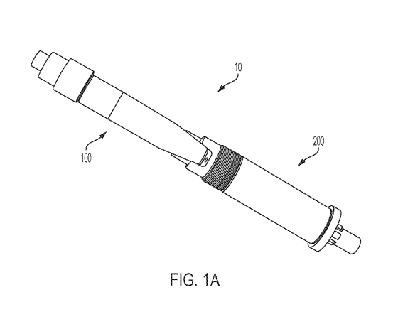
reference to FIG. 1A, a non-rotatable shaft/hub connection is provided.
The non-rotatable shaft/hub connection 10 comprises a shaft portion 100 and a
hub portion
200. As shown in FIGS. 1B-C, the shaft portion 100 comprises a shaft body 102,
a tapered
proximal end 104, and a distal end 106.
[0036] As
shown in FIGS. 1-2, the shaft body 102 is generally cylindrical having a
central axis A and a bore 108 extending along the central axis and throughout
the shaft
body 102 (i.e. extending from the tapered proximal end 104 to and through the
distal end
106). It should be understood that the shaft body 102 can be made of most any
material
sufficient to provide adequate torque transmission. In some embodiments, the
shaft body
102 is made of aluminum, iron, steel, carbon steel, stainless steel, or the
like.
CA 03138512 2021-10-28
WO 2020/223143
PCT/US2020/030037
[0037] It should also be understood that the shaft body 102 can be of any
length
sufficient to provide the shaft/hub connection. In some embodiments, the shaft
body 102
is at least 100 millimeters (mm) in length.
[0038] With reference to FIGS. 1-4, the shaft 100 comprises a tapered
proximal end
104. The tapered proximal end 104 provides an angled, tapered "double-D"
configuration,
comprising a pair of tapered, angled faces 104a, 104b and an end face 104c.
This "double-
D" configuration should be understood as providing a shaft end with a
flattened-round
shape (sometimes referred to as "diametrically opposed flats"), wherein the
two flattened
portions are opposite to each other (i.e. the edges of the pair of angled
faces 104a, 104b),
and the two round portions of the flattened-round shape are opposite to each
other and are
consistent with the cylindrical shape of the shaft body 102 (as best shown in
FIGS. 3-4).
Through this tapered double-D configuration, the tapered proximal end 104
allows torque
to be transmitted/transferred, yet removes backlash when tightened together
axially with a
bolt or similar fastener.
[0039] As opposed to traditional conical faces, the angled faces 104a, 104b
allow for a
taper-quality that fits with the torque capacities of anti-rotation features
and allows for easy
disassembly without special tools (e.g. like a press-fit application would
require).
[0040] The angled faces 104a, 104b are opposite to each other, wherein the
angle of
each face is angled toward the central axis A (as best shown in FIG. 2), and
where each
angled face 104a, 104b is tapered. In some embodiments, the angled faces 104a,
104b are
angled at an angle that is greater than 5 . In other embodiments, the angled
faces 104a,
104b are angled at an angle of approximately 5-25 .
[0041] In some embodiments, the angled faces 104a, 104b are identical in
dimension
and surface area. However, it should be understood that the angled faces 104a,
104b can
be of the same or different dimension and surface area, as long as the tapered
proximal end
104 provides a tapered double-D configuration.
[0042] With reference to FIGS. 5A-B, the distal end 106 of the shaft
portion 100 is
provided. The bore 108 extends along the central axis A and through the shaft
body 102
and is generally shaped to receive a fastener. In some embodiments, the
fastener is a
threaded fastener, bolt, or the like. The fastener is generally received by
the distal end 106,
where it passes through the bore 108.
6
CA 03138512 2021-10-28
WO 2020/223143
PCT/US2020/030037
[0043] As best
shown in FIG. 5A-C, the bore 108 includes an inner portion 108a and
an exterior end portion 108b, located toward the distal end 106 of the shaft.
The exterior
end portion 108b of the bore 108 provides a slightly larger circumference
(than as
compared to the inner portion 108a), such that a lip 108c is provided. As
shown in FIG.
5C, when a fastener 109 is received, the head of the fastener is abuttingly
engaged with the
lip 108c, so that when the fastener is tightened, the fastener provides the
axial clamp load
into the taper of the hub.
[0044] Now
referring to FIGS. 6-8, the non-rotatable shaft/hub connection further
comprises a hub portion 200. The hub portion 200 generally receives the shaft
portion 100
to provide the non-rotatable shaft/hub connection. It should be understood
that the hub
portion 200 can be made of the same or different material as the shaft portion
100.
[0045] As best
shown in FIG. 6, the hub portion 200 comprises a hub body 202, a hub
204, and a distal end 206. The hub body 202 is generally cylindrical having a
central axis
B extending along the central axis. It should be understood that the hub body
202 can be
made of most any material sufficient to provide adequate torque transmission.
In some
embodiments, the hub body 202 is made of aluminum, iron, steel, carbon steel,
stainless
steel, or the like.
[0046] In some
embodiments, the hub body 202 is at least 100 mm in length. It should
also be understood that the hub body 202 can be of any length sufficient to
provide the
shaft/hub connection.
[0047] The hub
204 is generally shaped or configured to receive the tapered proximal
end 104 of the shaft portion 100. The hub 204 comprises two, angled tapered
portions 204a,
204b, an interior hub face 204c, and an aperture 208. The tapered portions
204a, 204b are
angled in such a manner as to mirror, or be identical to, the angle of the
angled faces 104a,
104b of the tapered proximal end 104.
[0048] In some
embodiments, the hub 204 is provided in a pocket configuration (see
FIGS. 7A-B). This pocket configuration provides increased strength from
bursting and
driving torque. In such embodiments, the hub 204 fully receives and
encompasses the
tapered proximal end 104. In some embodiments, when fully received, the end
face 104c
of the tapered proximal end 104 abuttingly engages with the interior hub face
204c. In such
embodiments, the hub 204 is shaped to receive the exact configuration of the
tapered
7
CA 03138512 2021-10-28
WO 2020/223143
PCT/US2020/030037
proximal end 104, such that the tapered portions 204a, 204b are the exact size
and shape
of the angled faces 104a, 104b of the tapered proximal end 104. In other
embodiments, the
tapered portions 204a, 204b are not the exact size and shape of the angled
faces 104a, 104b
of the tapered proximal end 104, yet still provide the same lash-free benefits
of the
disclosed technology.
[0049] In some
embodiments, the hub 204 is provided in a forked configuration (see
FIGS. 8-10). In such embodiments, the two, angled tapered portions 204a, 204b
extend
essentially through the entire hub 204, where the angled tapered portions
204a, 204b are
provided by two prongs 210a, 210b, respectively (as best shown in FIG. 10B).
The prongs
210a, 210b are also angled in the same manner as the angle of the angled faces
104a, 104b
of the tapered proximal end 104 (as best shown in FIG. 11A).
[0050]
Referring now to FIGS. 11A-B, when the hub 204 fully receives the tapered
proximal end 104, the tapered portions 204a, 204b of the hub 204 abuttingly
engage with
the angled faces 104a, 104b of the tapered proximal end 104 (as best shown in
FIG. 11B).
In some embodiments, when the tapered proximal end 104 is received by the hub
204, the
engagement of the angled faces 104a, 104b with angled tapered portions 204a,
204b
complete the profile of the shaft body 102. In some embodiments, when
received, the end
face 104c of the tapered proximal end 104 does not abuttingly engage with the
interior hub
face 204c.
[0051] As
shown in FIGS. 12A-C, the tapered proximal end 104 and the hub 204 are
shown coupled together to provide the non-rotatable shaft/hub connection 10.
When
coupled, the bore 108 of the shaft portion 100 and the aperture 208 of the hub
portion 200
are axially aligned, such that the fastener 109 is able to pass through the
bore 108 of the
shaft body 102 and engage the aperture 208 to axially clamp together the shaft
portion 100
and the hub portion 200 (as best seen in FIGS. 12B-C).
[0052] By
axially clamping together the shaft 100 and the hub 200 (through the
threaded fastener 109), compressive force is provided through the double-D
configuration
and/or the interaction of the angled faces 104a, 104b and the tapered portions
204a, 204b,
(i.e. the angled faces 104a, 104b are fixed and press against the tapered
portions 204a,
204b, and vice versa). The double-D configuration of the non-rotatable
shaft/hub
connection provides the constant contact or compressive force required during
rotation of
8
CA 03138512 2021-10-28
WO 2020/223143
PCT/US2020/030037
the shaft/hub connection to eliminate backlash. When this constant contact is
maintained,
it eliminates any gaps, slippage, or rotation of the tapered proximal end 104
from the hub
204 (or vice versa) while torque is being transferred, and provides a lash-
free connection.
[0053] With
reference to FIGS. 12-13, in some embodiments, the shaft/hub connection
further comprises a collar 212. The collar 212 is placed around hub 204,
specifically
encompassing the outer exterior of the two prongs 210a, 210b. The collar 212
provides
additional alignment, strength, and stability to the shaft/hub connection
during rotation. It
should be understood that the collar 212 can be clamped together by/through
any
conventional means, such as, but not limited to, a set screw, c-style or u-
style clamp, etc.
[0054] While
embodiments of the disclosed technology have been described, it should
be understood that the present disclosure is not so limited and modifications
may be made
without departing from the disclosed technology. The scope of the disclosed
technology
is defined by the appended claims, and all devices, processes, and methods
that come
within the meaning of the claims, either literally or by equivalence, are
intended to be
embraced therein.
9