Note: Descriptions are shown in the official language in which they were submitted.
Attorney Docket No. 1246P002CA02
RETROFIT FOR FARM EQUIPMENT
TECHNICAL FIELD
The present invention relates to farm equipment. More specifically, the
present invention
relates to the retrofitting of farm equipment to result in more useful
equipment.
BACKGROUND
Advances in farming equipment have increased their efficiency, productivity,
and have
lowered their prices. Such advances have allowed farmers to accomplish more
with the
various forms of farm machinery. However, farm machinery built for one type of
crop may
not be suitable for other types of crops. As an example, one type of crop may
require farm
machinery to have a certain minimum ground clearance while other types of
crops may
require a different ground clearance.
The above is true for, among other types of farm machinery, sprayers. Some
types of crops
require sprayers to be above the resulting crops while others need to have the
sprayers closer
to the ground. Unfortunately, most farm equipment, including sprayers, do not
have
configurable ground clearances. This deficiency has led to farmers needing to
purchase
different farm equipment for different crops, with a corresponding increase in
the costs of
planting different crops.
There is therefore a need for systems, methods, or devices that will allow for
a retrofit of
existing farm equipment to allow such equipment to be used for different crops
of different
heights.
SUMMARY
The present invention provides systems and methods relating to the replacement
of specific
parts in farm equipment to thereby adjust the farm equipment's capabilities.
To modify the
ground clearance of farm equipment, especially sprayers with a strut type
suspension, the
spindles of the suspension system along with the air spring absorber are
replaced. The
original spindles are replaced with longer spindles while the air spring
absorber is replaced
- 1 -
Date Recue/Date Received 2021-11-16
Attorney Docket No. 1246P002CA02
with one that allows for an increased range of travel. As well, the fixed
linkage arms that
connect the air height control valves to the suspension system are also
replaced with longer
arms. These longer linkage arms may be of a fixed length or they may be of an
adjustable
length.
In a first aspect, the present invention provides a kit for retrofitting farm
equipment, said farm
equipment having a suspension system that includes original spindles, original
spring
mechanisms, and at least one original linkage arm, the kit comprising:
at least one pair of replacement spindles for replacing said original
spindles, said
replacement spindles being longer than said original spindles;
at least one replacement spring mechanism for replacing said original spring
mechanisms on said suspension system;
wherein
after said kit has been installed on said farm equipment, said farm equipment
has a
higher ground clearance;
said higher ground clearance is partially due to more travel by said
suspension
system when said at least one replacement spring mechanism has been installed.
In a second aspect, the present invention provides a method for retrofitting
farm equipment,
the method comprising:
locating at least one original spindle installed on said farm equipment, said
at least
one original spindle being installed on a suspension system of said farm
equipment;
removing said at least one original spindle;
replacing said at least one original spindle with at least one replacement
spindle, said
at least one replacement spindle being longer than said at least one original
spindle;
locating at least one original spring mechanism installed as part of said
suspension
system on said farm equipment;
replacing said at least one original spring mechanism with at least one
replacement
spring mechanism, said at least one replacement spring mechanism allowing more
travel of said suspension system than said at least one original spring
mechanism.
- 2 -
Date Recue/Date Received 2021-11-16
Attorney Docket No. 1246P002CA02
BRIEF DESCRIPTION OF THE DRAWINGS
The embodiments of the present invention will now be described by reference to
the
following figures, in which identical reference numerals in different figures
indicate identical
elements and in which:
FIGURE 1 is an exploded view of a strut-type suspension system for farm
equipment;
FIGURE 2 is an exploded view of an automatic air hose assembly for farm
equipment;
FIGURE 3 illustrates an original spindle and a longer replacement spindle;
FIGURE 4A shows a replacement bracket in use with an original linkage arm;
FIGURE 4B shows a replacement bracket in use with a linear actuator;
FIGURE 4C illustrates a replacement bracket in used with a pneumatic linear
actuator;
FIGURE 4D shows another view of the replacement bracket and pneumatic
linear actuator of Figure 4C;
FIGURE 4E shows a further view of the pneumatic linear actuator and
replacement bracket of Figure 4C;
FIGURE 4F illustrates a replacement bracket which may be used with some
implementations of the present invention;
FIGURE 5 illustrates an original linkage arm and a longer replacement linkage
arm;
FIGURE 6 illustrates an electrical linear actuator which may be used with the
present invention;
FIGURE 7 shows a suspension system that has been retrofitted according to one
aspect of the present invention;
- 3 -
Date Recue/Date Received 2021-11-16
Attorney Docket No. 1246P002CA02
FIGURE 8 is a view of the retrofitted suspension system according to one
aspect
of the invention; and
FIGURE 9 illustrates a self-propelled sprayer farm equipment on which the
various aspects of the present invention may be practiced.
DETAILED DESCRIPTION
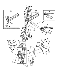
Referring to Figure 1, an exploded view of a right hand side suspension system
for a self-
propelled sprayer is illustrated. The suspension system illustrated in Figure
1 is a strut-based
system and can be described as a dual strut air spring suspension. As can be
seen in Fig. 1,
an original spindle 48 is illustrated. To adjust the clearance height of the
self-propelled
sprayer, both original spindles are to be replaced with longer replacement
spindles. The
length of the replacement spindles, and thus the final adjusted height of the
sprayer, may be
controlled by a travel limiting device such as a spacer, bumper, or stop on or
near the
replacement spindle. Depending on the implementation, o-rings, bushings,
screws, bolts,
nuts, and spacers (such as components 44, 45, 46, 28, 29, 10, and 3) may be
used to fix the
replacement spindle in the suspension system as well as to control the final
adjusted height of
the sprayer. Since the replacement spindle would be one component that
controls the
distance allowed for the suspension system to move up and down, a suitable
device that limits
the travel of the suspension system, such as a spacer or a bumper, can be used
to limit how
far this distance is.
Also to be replaced is the original air spring 38. This air spring 38, also
known as an
absorber or a spring mechanism, is to be replaced with a replacement air
spring or absorber
that allows for greater or further travel than the original air spring. As
with the spindles, a
travel limiting device, such as a suitable bumper or spacer or stop, can also
be used to control
how far the suspension system travels or moves up and down. Installing a
suitable spacer or
bumper can limit the amount of travel that the suspension system can undergo.
It should be clear that Figure 1 illustrates only one strut suspension
assembly. A
corresponding left hand side suspension assembly would also need to have its
spindles
replaced along with the corresponding absorber.
- 4 -
Date Recue/Date Received 2021-11-16
Attorney Docket No. 1246P002CA02
In addition to the above components, the original linkage arms that link the
automatic air
height control valve assembly to the air spring in the suspension system must
also be replaced
with longer linkage arms. Referring to Figure 2, an exploded view of the
automatic air height
control valve assembly is illustrated. The original linkage arms 45 in the
figure are clearly
illustrated and these would need to be replaced. It should be noted that
current designs of
sprayers use fixed length linkage arms. However, these linkage arms can be
replaced with
other fixed length linkage arms or adjustable linkage arms. As well,
adjustable replacement
linkage arms can be mechanical, pneumatic, or electrical type linkage arms.
Depending on
the configuration, these adjustable replacement linkage arms may be extended
or shortened
from within the driver's cab of the sprayer. Similarly, the adjustable
replacement linkage
arms may be adjusted from outside the driver's cab. In one implementation,
each linkage arm
was replaced by a linear actuator. Depending on the implementation and the
configuration of
the linkage arms, custom brackets may need to be used to attach the
replacement linkage arm
to the points where the original linkage arms were attached. As noted
previously, linear
actuators may be used as replacement linkage arms. Using linear actuators
would allow for
better control of the length of the replacement linkage arm.
In another implementation, the original linkage arms are not replaced but the
bracket
attaching the original linkage arms is replaced to allow for the greater
ground clearance
height. This may be done by installing a replacement bracket that has multiple
attachment
points to allow for greater ground clearance heights for the farm equipment.
Of course, such
brackets may also be used with the longer replacement linkage arms for even
larger ground
clearance heights.
It should be clear that the original spindle and the replacement spindle have
the same
dimensions except for length. As can be seen in Fig. 3, the original spindle
48 and the
replacement spindle 48A are similar in size except for length, with the
replacement spindle
being longer. The widths of the two spindles are to be as identical as
possible to ensure that
the original spindle 48 can be replaced with the replacement spindle 48A. As
noted above,
other components such as brackets, braces, nuts, and spacers may be used to
secure the
replacement spindle and to control the allowed travel for the suspension
system.
Referring to Figure 5, the original linkage arm 45 and the replacement linkage
arm 45A
should, much like the spindles, be as identical as possible except for length.
The original
linkage arm 45 and the replacement linkage arm 45A are to be as identical as
possible except
- 5 -
Date Recue/Date Received 2021-11-16
Attorney Docket No. 1246P002CA02
that the replacement linkage arm 45A is to be longer than the original linkage
arm 45. This is
to accommodate the greater clearance height for the retrofitted farm
equipment. As noted
above, both the linkage arm 45 and the replacement linkage arm 45A are of a
fixed length.
Referring to Figure 4F, a replacement bracket 100 is illustrated. As noted
above, the
replacement bracket has multiple attachment points 100A to allow for different
configured
ground clearance heights for the farm equipment. In one implementation, the
original linkage
arm is used, and the replacement bracket allows for the original linkage arm
45 to simply be
attached to the suspension system at a higher point than the original
configuration. This
allows for the greater clearance height of the farm equipment without
replacing the linkage
arm. Referring to Figure 4A, such an implementation is illustrated with an
original linkage
arm being used in conjunction with a replacement bracket 100 and a replacement
air spring
38A. As can be seen in Figure 4A, the linkage arm is attached at a higher
point in the bracket
100 to allow for a larger clearance height.
It should, however, be clear that, instead of a replacement bracket 100, an
original bracket
may be used in conjunction with a replacement linkage arm that is longer than
the original
linkage arm. The longer length of the replacement linkage arm accommodates the
greater
clearance height of the farm equipment.
In a further variant of the present invention, instead of a fixed length
linkage arm, a linear
actuator may be used in place of the original linkage arm. This may be used in
conjunction
with a replacement bracket to allow for a controllable clearance height.
Referring to Figure
4B, such an implementation is illustrated. As can be seen, a replacement air
spring 38A is
used along with a replacement bracket 100, and a linear actuator 45B. The
linear actuator
45B takes the place of a fixed length linkage arm. This allows for clearance
height
configurability from the cabin of the farm equipment. An electrical linear
actuator that may
be used in place of the fixed length linkage arm is also illustrated in Figure
6.
Referring to Figures 4C-4E, a further variant of the present invention is
illustrated. As can be
seen from Figures 4C-4E, a replacement bracket 100 is used in conjunction with
a pneumatic
linear actuator 45C to provide adjustability in terms of the ground clearance
of the farm
equipment. Figures 4C and 4D show the replacement bracket and the pneumatic
linear
actuator installed on a right wheel suspension of a piece of farm equipment
and the wheel
itself can be seen to the right of the pneumatic linear actuator. Figure 4E
shows the
- 6 -
Date Recue/Date Received 2021-11-16
Attorney Docket No. 1246P002CA02
replacement bracket and the pneumatic linear actuator installed on a left
wheel assembly of
the farm equipment with the wheel not present.
To retrofit a single self-propelled sprayer, each corner or wheel or strut
type suspension of the
sprayer would need to have its original spindles and absorber replaced. This
retrofit may also
involve replacing the original linkage arm and/or the bracket attaching the
linkage arm to the
suspension system. Since each wheel would need two replacement spindles and
one
replacement absorber, a single sprayer would thus need eight replacement
spindles and four
replacement absorbers. As well, since each wheel would need one replacement
bracket and/or
a replacement linkage arm, each sprayer would further need four replacement
brackets and/or
four replacement linkage arms.
Of course, the replacement spindles, air spring/absorbers, and linkage arms
will need to be at
least as sturdy as the original parts.
In another embodiment of the invention, the components needed to replace the
relevant parts
noted above can be assembled as a kit with a suitable set of instructions.
Accordingly, such a
kit would have eight replacement spindles and four replacement air springs.
Additionally,
each kit may contain four replacement brackets and/or four replacement linkage
arms. Of
course, each of the replacement linkage arms may be a longer replacement
linkage arm or a
linear actuator. A retrofitted suspension system is illustrated in Figure 7.
Another illustration
of a retrofitted suspension system is illustrated in Figure 8.
It should also be noted that while the above description and the accompanying
figures applies
to self-propelled sprayers (as shown in Figure 9), other farm equipment may
also be
retrofitted or adjusted in a similar manner. Any farm equipment that uses a
strut type
suspension system can have its ground clearance adjusted by locating the
spindles that
control the distance that the suspension system travels as well as the "shock
absorbers" or
spring mechanisms that also control the distance that the suspension system
travels, and
replacing these components. The spindles would be replaced by longer spindles
while the
spring mechanisms would be replaced by similar spring mechanisms that allow a
greater
travel distance. Other components that would be affected by the greater travel
of the
suspension systems would, of course, also need to be replaced to take into
account this
greater travel distance. One such component affected by the greater travel
would be the
linkage arm noted above and/or the bracket that attaches the linkage arm to
the suspension
system. As noted above, replacing the linkage arm with a replacement linkage
arm would not
- 7 -
Date Recue/Date Received 2021-11-16
Attorney Docket No. 1246P002CA02
necessitate replacing the bracket while replacing the bracket would not
necessitate replacing
the linkage arm. As well, the linkage arm may be replaced with a suitable
linear actuator.
Regarding implementation, experiments have shown that John Deere self-
propelled sprayers
models R4030, R4038, and R4045 are suitable for use with the invention. For
these models
of sprayers, the spindle (John Deere part number KK26139) and the air spring
or absorber
(John Deere part number AKK12461) would need to be replaced. Additionally, the
linkage
arm (John Deere part number AN403729) may need to be replaced (with either a
longer
linkage arm or a linear actuator) if the original bracket is to be retained.
However, if the
bracket is to be replaced, the original linkage arm may be retained. Of
course, both the
bracket and the linkage arm may both be replaced.
A person understanding this invention may now conceive of alternative
structures and
embodiments or variations of the above all of which are intended to fall
within the scope of
the invention as defined in the claims that follow.
- 8 -
Date Recue/Date Received 2021-11-16