Note: Descriptions are shown in the official language in which they were submitted.
- 1 -
TITLE OF INVENTION
WHEEL HUB, VEHICLE WITH AUXILIARY DRIVE, SAID VEHICLE
COMPRISING THE WHEEL HUB, AND CLAMPING ASSEMBLY
FIELD OF THE INVENTION
The invention relates to a wheel hub for a drive wheel of a
vehicle, an auxiliary driven bicycle and a clip arrangement
for the wheel hub.
BACKGROUND OF THE INVENTION
Electrically driven vehicles are gaining more and more
importance for meeting different individual mobility
requirements. In particular, the electric bicycle is on the
rise. The electric bicycle is a bicycle having an electric
motor as an auxiliary drive. An electric drive assistance is
conventionally requested by way of pedalling pedals which are
fastened to the pedal cranks of the bicycle when the pedals
are alternately pressed downward in a correspondingly
pronounced manner. A chain ring is mounted on the pedal
cranks in order to transmit a torque to the drive wheel of
the bicycle, the drive wheel typically being the rear wheel,
and the chain ring being coupled via a chain to a pinion
which is mounted on the rear wheel in a torsionally rigid
manner in the drive direction. The electric motor is
conventionally accommodated in the wheel hub of the rear
wheel as a hub motor, the supply of which with electric power
is brought about by rechargeable battery cells.
A measurement of a movement of the electric bicycle can be
provided in order to control the electric motor. The
measurement of the movement can for example be a velocity of
the electric bicycle, for example in order to guarantee that
the electric bicycle does not exceed a maximum velocity out
of security reasons. The velocity of the electric bicycle can
for example be determined by determining a rotational speed
of a hub. This can for example be carried out by means of a
CA 03139317 2021-11-23
- 2 -
pole ring and a magnetic field sensor that are accommodated
in the wheel hub. The pole ring comprises alternately in its
circumferential direction magnetic north poles and magnetic
south poles and the magnetic field sensor measures the
magnetic field originating from the pole ring. A relative
velocity between the pole ring and the magnetic field sensor
can be deduced out of the magnetic field that is changing
over time. It is hereby disadvantages that the magnetic field
sensor only works optimal if the magnetic field sensor is
arranged in a predetermined distance range to the pole ring,
wherein the distance range can be very narrow. In case the
magnetic field sensor is arranged outside of the distance
range, the measurement of the relative movement between the
pole ring and the magnetic field sensor is only imprecise.
It is therefore an object of the invention to provide a
device for a drive wheel of a vehicle, wherein a precise
measurement of a movement can be performed with the device.
SUMMARY OF THE INVENTION
The inventive wheel hub for a drive wheel of a vehicle
comprises a wheel axle, a clip that encompasses an outer
surface of the of the wheel axle in a C-shape manner and is
mounted torsionally rigid against the wheel axle, a magnetic
field sensor that is mounted on the clip, and a pole ring
that is arranged concentrically around the wheel axle and in
a distance to the magnetic field sensor as well as is
supported such that the pole ring can rotate relatively to
the wheel axle, wherein the magnetic field sensor is adapted
to detect a magnetic field that originates from the pole
ring, so that a movement of the pole ring relative to the
wheel axle can be deduced.
The magnetic field sensor can be arranged in a defined
distance to the pole ring by means of the clip. The defined
distance can thereby be chosen such that it is in a distance
range to the pole ring, wherein the magnetic field sensor
works optimal in the distance range. By arranging the
CA 03139317 2021-11-23
- 3 -
magnetic field sensor in the distance range, a device is
provided with which a measurement of the movement of the pole
ring relative to the wheel axle can be performed with a high
precision.
The pole ring comprises alternately in its circumferential
direction magnetic north poles and magnetic south poles. In
principle, the invention can be carried out with a single one
of the north poles and a single one of the south poles, but
wherein the precision of the measurement of the movement of
the pole ring relative to the wheel axle is higher if a
plurality of the north poles and the south poles is provided.
The magnetic field sensor can for example be adapted to
determine a velocity of the pole ring relative to the wheel
axle. It is alternatively conceivable that the magnetic field
sensor is adapted to determine a direction of the movement of
the pole ring relative to the wheel axle. Therefore, it can
advantageously be distinguished between a forward movement
and a backward movement of the drive wheel. Exemplary sensors
are the sensors AK 8777B and AK 8778B of the company Asahi
Kasai. In addition, the magnetic field sensor can be adapted
to determine also the velocity of the pole ring relative to
the wheel axle in addition to the direction of the movement
of the pole ring relative to the wheel axle. This can also be
accomplished by the sensors AK$7773 and AK 8778B of the
company Asahi Kasai.
The velocity can for example be a rotational speed and/or an
angular velocity. It is also possible to calculate the
rotational speed and/or the angular velocity with a diameter
of the drive wheel in order to determine a vehicle velocity
of a vehicle that comprises the drive wheel. The magnetic
field sensor can for example be a Hall sensor. The distance
can be an axial distance and/or a radial distance.
The clip can be mounted force-fittedly on the wheel axle, so
that the clip is mounted torsionally rigid against the wheel
axle. For this purpose, the clip can be under a mechanical
CA 03139317 2021-11-23
- 4 -
stress in its mounted state. By the force-fit mounting of the
clip on the wheel axle, it is not required to provide a
fastening means, for example a screw or a rivet. The clip can
thereby be mounted on the wheel axle by a simple imposing of
the clip over the wheel axle. In addition, in the case that
the magnetic field sensor works erroneously, the magnetic
field sensor can simply be exchanged by exchanging the clip
together with the magnetic field sensor. It is additionally
conceivable, that the clip is mounted form-fittedly on the
wheel axle, so that the clip is mounted torsionally rigid
against the wheel axle. It is also conceivable that the clip
is mounted on the wheel axle force-fittedly as well as form-
fittedly.
It is preferred that the wheel hub comprises a pinion carrier
on which at least one pinion can be mounted torsionally rigid
or a belt pulley for driving the drive wheel, a transmission
sleeve that is coupled torsionally rigid with the belt pulley
or the pinion carrier as well as is supported concentrically
around the wheel axle and such that it can rotate relative to
the wheel axle, a hub casing and a freewheel via which the
transmission sleeve is coupled with the hub casing, wherein
the pole ring is mounted torsionally rigid on the
transmission sleeve. A torque can thereby be transferred from
belt pulley or the pinion carrier via the transmission sleeve
and via the freewheel to the hub casing. Since the pole ring
is mounted torsionally rigid on the transmission sleeve, the
pole ring rotates always relative to the magnetic field
sensor that is mounted torsionally rigid against the wheel
axle when the pinion carrier or the belt pulley is driven.
This is for example the case when the pinion is mounted
torsionally rigid on the pinion carrier and the pinion is
driven by a pedalling of a rider. On the other hand, if the
rider stops to pedal, the pinion together with the pinion
carrier and the transmission sleeve are standing still
relative to the magnetic field sensor. In this case, by
providing the freewheel, the hub casing can on the other hand
further rotate against the wheel axle. The magnetic field
CA 03139317 2021-11-23
- 5 -
sensor therefore measures a relative movement between the
pole ring and the wheel axle always when the rider pedals and
no movement between the pole ring and the wheel axle when the
rider does not pedal. It is thereby for example possible, in
the case that the wheel hub is provided in an electric
bicycle with a motor, to immediately switch off the motor by
using the measured movement between the pole ring and the
wheel axle, when the rider stops to pedal. In the case that
the magnetic field sensor is provided that is adapted to
determine the direction of the movement of the pole ring
relative to the wheel axle, the motor can also be immediately
switched off, when the rider pedals backwards. The motor can
be an electric motor.
It is preferred that the wheel axle is made, at least in
parts, as a hollow shaft and therefore comprises a cavity as
well as comprises a wheel axle through hole that extends
through wheel axle from the outer surface of the wheel axle
to the cavity, wherein the clip comprises a clip through hole
and a region that confines the clip through hole, wherein the
region engages form-fittedly in the wheel axle through hole.
The clip is thereby mounted even more torsionally rigid on
the wheel axle and in addition, an axial displacement of the
clip is prevented. In addition, the clip through hole and the
wheel axle through hole can advantageously be used to guide
an electric wiring of the magnetic field sensor in the
cavity.
An electric wiring of the magnetic field sensor is preferably
guided through the clip through hole and through the wheel
axle through hole in the cavity. The electric wiring of the
magnetic field sensor can then be guided out of the wheel
axle on another position of the wheel axle. The other
position can for example be a front side of the wheel axle
and/or the wheel axle can comprise a wheel axle recess that
extends through the wheel axle from the outer surface of the
wheel axle to the cavity.
CA 03139317 2021-11-23
- 6 -
It is preferred that the wheel axle comprises a flattened
region on the outer surface of the wheel axle and an inner
surface of the clip comprises two circular arc-shaped
sections and between the two circular arc-shaped sections a
straight section, wherein the two circular arc-shaped
sections and the straight section are arranged next to each
other in a circumferential direction of the wheel axle,
wherein the straight section contacts the flattened region
and the circular arc-shaped sections contact the regions of
the wheel axle which are arranged adjacent to the flattened
region. The clip is thereby mounted form-fittedly on the
wheel axle, whereby the clip is mounted even more torsionally
rigid on the wheel axle. In the case that the wheel axle
through hole is provided, it is preferred that the wheel axle
through hole is provided in the flattened part. A larger
space is thereby available for a wiring of the magnetic field
sensor, as it would be the case, if the flattened part would
not be provided, wherein the wiring is guided through the
wheel axle through hole. Because of the larger space, the
wiring can be guided with a larger curvature radius as it
would be the case without the flattened region, whereby a
cable break is less likely.
It is preferred that the magnetic field sensor is arranged on
an outer surface of the clip. It is thereby preferred that
the clip comprises an L-shaped protrusion with two arms,
wherein the protrusion protrudes from the outer surface of
the clip and the wheel hub comprises a magnetic field sensor
circuit board, on which the magnetic field sensor is
arranged, wherein the magnetic field sensor circuit board is
clamped between one of the two arms and the outer surface of
the clip. The magnetic field sensor circuit board together
with the magnetic field sensor are thereby mounted on the
clip. The assembling of the magnetic field sensor circuit
board on the clip is due to the clamping relatively simple
and, for example, it is not necessary to perform gluing. It
is particular preferred that the magnetic field sensor
circuit board abuts on the other of the two arms. Thereby,
CA 03139317 2021-11-23
- 7 -
the position of the magnetic field sensor circuit board is
also defined in a circumferential direction of the wheel
axle.
It is preferred, that the clip is made out of an elastic
material, in particular an elastic plastic material. Since
the clip can deform during imposing the clip over the wheel
axle in a radial direction of the wheel axle due to its
elastic material, the clip can advantageously be simply
mounted on the wheel axle. In addition, the elastic material
dampens vibrations that are transferred from the wheel axle
on the magnetic field sensor, whereby the magnetic field
sensor is subjected to few vibrations. Therefore, on one
hand, the lifetime of the magnetic field sensor is long and,
on the other hand, the magnetic field sensor barely changes
the distance to the pole ring during the vibrations, whereby
the precision during measuring the movement is high also
during an occurrence of the vibrations.
The wheel hub preferably comprises a torque measuring device.
Therefore, a further information besides the movement is
available. For example, in the case that the wheel hub is
provided in the electric bicycle with the motor, by means of
the torque measuring device it is possible that the motor
supports the rider with a high power, in the case that the
rider rides uphill and applies a high torque, and the motor
supports the rider only with a low power, in the case that
the rider rides downhill and applies only a low torque.
It is preferred that the wheel hub comprises a first plug
part that is mounted on the clip and the torque measuring
device comprises a torque measuring circuit board with a
second plug part that is mounted on the torque measuring
circuit board and is in engagement with the first plug part.
The clip therefore defines the position of the torque
measuring circuit board via the first plug part and the
second plug part. In addition, it is possible to guide an
electric wiring of the magnetic field sensor and an electric
CA 03139317 2021-11-23
- 8 -
wiring of the torque measuring device along a single wiring
harness. As an alternative to the plug parts, the torque
measuring circuit board can be fixedly connected to the clip.
It is preferred that an electric wiring of the torque
measuring device is guided via the first plug part and via
the second plug part. In the case that the wheel axle through
hole and the clip through hole are provided, it is preferred
that the electric wiring of the torque measuring device is
guided through the wheel axle through hole and the clip
through hole into the cavity.
It is preferred that the wheel hub comprises a pinion carrier
on which at least one pinion can be mounted torsionally rigid
or a belt pulley for driving the drive wheel, a transmission
sleeve that is coupled with the pinion carrier or the belt
pulley torsionally rigid as well as is supported
concentrically around the wheel axle and such that it can
rotate relative to the wheel axle, a hub casing and a
freewheel, via which the transmission sleeve is coupled with
the hub casing, wherein the transmission sleeve comprises a
magnetically coded material which magnetic properties change
under the influence of a torque acting on the transmission
sleeve, and the torque measuring device comprises a sensor
that is arranged on the torque measuring circuit board and is
adapted to detect the changing magnetic properties. The
magnetic properties change due to magnetostriction. The
torque can be deduced out of the changing magnetic properties
that are detected by the sensor, wherein the torque acts on
the transmission sleeve and is transferred starting from the
pinion carrier or the belt pulley to the hub casing. The
sensor can comprise a coil or several coils.
It is preferred that the wheel hub comprises a motor that is
adapted to drive the drive wheel. The motor can for example
be an electric motor. It is particularly preferred that the
motor is arranged inside of the hub casing of the wheel hub.
In addition, it is particularly preferred that the motor is
CA 03139317 2021-11-23
- 9 -
adapted to transfer a motor torque to the hub casing, wherein
the motor torque is not transferred via the transmission
sleeve. It is therefore advantageously achieved that only the
torque applied by the rider is measured by the transmission
sleeve.
The auxiliary driven vehicle according to the invention
comprises the wheel hub with the motor, the drive wheel and a
control device that is adapted to control the motor adapted
to measurement data measured by the magnetic field sensor. It
is preferred that the control device is adapted to control
the motor additionally adapted to measurement data measured
by the torque measuring device. The auxiliary driven vehicle
is in particular an electric bicycle with a storage that is
adapted to store electric energy and to deliver the electric
energy to the motor. The storage can for example comprise
accumulator cells.
The inventive clip arrangement for a wheel axle comprises a
clip that is adapted to encompass the wheel axle in a C-
shaped manner and to be mounted torsionally rigid against the
wheel axle, and a magnetic field sensor that is mounted on
the clip.
It is preferred that the clip comprises a clip through hole
and a region that confines the clip through hole, wherein the
region protrudes from an inner surface of the clip. It is
particularly preferred that an electric wiring of the
magnetic field sensor is guided through the clip through
hole.
It is preferred that an inner surface of the clip comprises
two circular arc-shaped sections and a straight section
between the two circular arc-shaped sections, wherein the two
circular arc-shaped sections and the straight section are
arranged next to each other in a direction from a first
longitudinal end of the clip to a second longitudinal end of
the clip.
CA 03139317 2021-11-23
- 10 -
It is preferred that the magnetic field sensor is arranged on
an outer surface of the clip. It is thereby particular
preferred that the clip comprises and L-shaped protrusion
with two arms, wherein the protrusion protrudes from the
outer surface of the clip and the clip arrangement comprises
a magnetic field circuit board on which the magnetic field
sensor is arranged, wherein the magnetic field sensor circuit
board is clamped between one of the two arms and the outer
surface of the clip. In addition, the magnetic field sensor
circuit board can abut on the other of the two arms.
It is preferred that the clamp is made out of an elastic
material, in particular an elastic plastic material.
It is preferred that the clip comprises a first plug part
that is mounted on the clip and is adapted to be in
engagement with a second plug part. The first plug part and
the second plug part are thereby particularly preferably
adapted to transmit signals of a sensor that is different
from the magnetic field sensor.
It is preferred that the clip exceeds in the circumferential
direction of the wheel axle and angle larger than 180 . The
angle is particularly preferably larger than 190 .
BRIEF DESCRIPTION OF THE DRAWINGS
In the following, the invention is explained on the basis of
the attached schematic drawings.
Figure 1 shows a perspective view of a wheel hub, wherein the
wheel hub is assembled.
Figure 2 shows a longitudinal section through the wheel hub.
Figure 3 shows a perspective view of the wheel hub, wherein
the wheel hub is open.
Figure 4 shows a cross section through the wheel hub.
Figure 5 shows a perspective view of a clip.
CA 03139317 2021-11-23
- 11 -
Figure 6 shows a top view on the clip.
Figure 7 is similar to Figure 2, but shows a larger section
of the wheel hub.
DETAILED DESCRIPTION OF THE PREFERRED EMBODIMENT
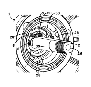
As it can be seen from Figures 2 to 4, a wheel hub 1 for a
drive wheel of a vehicle comprises a wheel axle 2, a clip 7,
a magnetic field sensor 8 and a pole ring 9. The clip 7
encompasses an outer surface of the wheel axle 2 in C-shaped
manner and is mounted torsionally rigid against the wheel
axle 2. In order to form the clip 7 particularly torsionally
rigid, the clip 7 can exceed in circumferential direction of
the wheel axle 2 and angle larger than 1800, in particularly
larger than 1900, as it can be seen in particular in Figure
4. The pole ring 9 is arranged concentrically around the
wheel axle 2 and in a distance to the magnetic field sensor
8. In addition, the pole ring 9 is supported such that it can
rotate relative to the wheel axle 2. The pole ring 9
comprises alternately in its circumferential direction
magnetic north poles and magnetic south poles, wherein, in
principle, only a single one of the north poles and a single
one of the south poles is conceivable. The magnetic field
sensor 8 is mounted on the clip 7 and adapted to detect a
magnetic field that originates from the pole ring 9, so that
a movement of the pole ring 9 relative to the wheel axle 2
can be deduced. By means of the clip V, it is advantageously
possible to define the distance of the magnetic field sensor
8 to the pole ring 9 with a high precision. The distance of
the magnetic field sensor 8 to the pole ring 9 according to
Figures 2 to 4 is a radial distance, wherein the magnetic
field sensor 8 and the pole ring 9 are arranged in the same
axial position. Therefore, no axial distance is provided
according to Figures 2 to 4. Alternatively, it is conceivable
that the distance of the magnetic field sensor 8 to the pole
ring 9 is an axial distance and that the magnetic field
sensor 8 and the pole ring 9 are arranged in the same radial
CA 03139317 2021-11-23
- 12 -
position. In addition, it is conceivable that a radial
distance as well as an axial distance are provided. If the
radial distance and no axial distance are provided, a surface
of the magnetic field sensor 8, wherein the surface is facing
toward the pole ring 9, can be arranged perpendicular to a
radial direction of the wheel hub 1, as it is for example
shown in Figure 4.
As it can be seen from Figure 1, the wheel hub 1 comprises a
hub casing 3. The wheel hub 1 comprises a motor that is
arranged inside of the hub casing 3 and is adapted to drive
the drive wheel. The wheel axle 2 can be formed in one piece.
Alternatively, the wheel axle 2 can be formed in two pieces
with two partial wheel axles that have an axial distance to
each other. The space between the two partial wheel axles can
be used by the motor. The motor can be an electric motor. The
hub casing 3 can comprise outside of the hub casing 3 two
spoke flanges with holes that are provided for hanging in
spokes of the drive wheel. The wheel axle 2 is provided to be
fixedly attached on an auxiliary driven vehicle that
comprises the drive wheel. For example, the wheel axle 2 can
be fixedly attached on a frame of an electric bicycle. For
this purpose, a respective thread 32 can be provided on both
longitudinal ends of the wheel axle 2, as it is shown in
Figure 1. The pole ring 9 can be arranged torsionally rigid
against the hub casing 3. Therefore, a relative movement
between the pole ring 9 and the wheel axle 2 will always be
measurable when the drive wheel rotates relatively to the
wheel axle 2. Alternatively, it is conceivable that the pole
ring 9 is arranged torsionally rigid against a pinion carrier
4 of the wheel hub 1, wherein at least one pinion can be
mounted torsionally rigid on the pinion carrier 4 for driving
the drive wheel. Therefore, a relative movement between the
pole ring 9 and the wheel axle 2 will always be measurable
when the pinion carrier 4 rotates relatively to the wheel
axle 2.
CA 03139317 2021-11-23
- 13 -
As it can be seen from Figure 2, the wheel hub 1 comprises
the pinion carrier 4, a transmission sleeve 5, the hub casing
3 and a freewheel 6. At least one pinion can be mounted on
the pinion carrier 4 torsionally rigid for driving the drive
wheel. The transmission sleeve 5 is coupled torsionally rigid
with the pinion carrier 4 and is supported concentrically
around the wheel axle 2 and such that it can rotate
relatively to the wheel axle 2. Alternatively to the pinion
carrier 4, also a belt pulley can be provided that it is
adapted to be driven by a belt, in particularly by a toothed
belt, and that is coupled torsionally rigid with the
transmission sleeve 5. The pole ring 9 is mounted torsionally
rigid on the transmission sleeve 5. The transmission sleeve 5
is coupled with the hub casing 3 via the freewheel 6. The
transmission sleeve 5 has a first longitudinal end 35 and a
second longitudinal end 36, wherein the first longitudinal
end 35 is the axial outer longitudinal end of the
transmission sleeve 5. As it is illustrated in Figure 7, the
transmission sleeve 5 can be coupled torsionally rigid with
the pinion carrier 4 in the region of the first longitudinal
end 35, and the freewheel 6 can be arranged in the region of
the second longitudinal end 36. In addition, it is
conceivable that in the region of the first longitudinal end
36 a first bearing 12a is provided that is arranged in radial
direction between the wheel axle 2 and the transmission
sleeve 5 and supports the transmission sleeve 5 such that it
can rotate relatively to the wheel axle 2. In addition, it is
conceivable that a second bearing 12b is provided that is
arranged in an axial position that is free from the
transmission sleeve 5 and in a radial direction between the
wheel axle 2 and the hub casing 3 and supports the hub casing
3 such that it can rotate relatively to the wheel axle 2.
Figures 3 and 4 show that the freewheel 6 is formed by a
plurality of locking pawls 28 that are mounted on the hub
casing 3 and a locking wheel 29 that is formed by the
transmission sleeve 5. The locking wheel 29 can comprise a
multitude of protrusions 14 that are arranged on the outer
CA 03139317 2021-11-23
- 14 -
surface of the transmission sleeve 5 and engage in the
locking pawls 28 during rotation of the freewheel 6 in its
locking direction.
The transmission sleeve 5 can comprise on its front surface
41 in the region of the second longitudinal end 36 a ring
shaped transmission sleeve protrusion 34 that protrudes in
axial direction from the transmission sleeve 5 for mounting
the pole ring 9 on the transmission sleeve 5. The pole ring 9
can be arranged inside of the transmission sleeve protrusion
34 and be supported by the transmission sleeve protrusion 34.
In addition, the pole ring 9 can contact the front surface of
the transmission sleeve 5 as it is illustrated in Figure 2.
Therefore, a definition of the position of the pole ring 9 in
axial direction is obtained. In addition, it is conceivable
that between the pole ring 9 and the transmission sleeve
protrusion 34 a clamping ring 30 is arranged, wherein the
clamping ring 30 contacts radially outside the transmission
sleeve protrusion 34 and radially inside the pole ring 9. The
clamping ring 30 can comprise clamping ring protrusions that
are arranged in a distance in circumferential direction as it
is illustrated in Figures 3 and 4, wherein the clamping ring
protrusions 37 engage in corresponding transmission sleeve
recesses that are arranged in the transmission sleeve
protrusion 34. The clamping ring 30 can for example comprise
a plastic material, steel or spring steel or consist out of
the plastic material, steel, steel or spring steel.
As it can be seen from Figures 2 to 4, the wheel axle 2 is
formed at least partially as a hollow shaft and therefore
comprises a cavity 26. The cavity 26 can extend along the
complete length of the wheel axle 2 as it shown in Figure 4.
Figure 4 shows additionally that the wheel axle 2 comprises a
wheel axle through hole 27 that extends through the wheel
axle 2 from the outer surface 39 of the wheel axle 2 to the
cavity 26. The clip 7 comprises a clip through hole 24 and a
region that confines the clip through hole 24, wherein the
region engages form-fittedly in the wheel axle through hole
CA 03139317 2021-11-23
- 15 -
27. The region that confines the clip through hole 24 can be
formed by a ring 25. The ring 25 can be circular shaped and
can also have a shape that differs from the circular shape,
as it is illustrated in Figure 6. An electric wiring of the
magnetic field sensor 8 can be guided through the clip
through hole 24 and through the wheel axle through hole 27 in
the cavity 26. The electric wiring of the magnetic field
sensor 8 can be guided out of the wheel axle 2 on another
position of the wheel axle 2. The other position can for
example be a front surface 40 of the wheel axle 2 and/or the
wheel axle 2 can have a wheel axle recess that extends
through the wheel axle 2 from the outer surface of the wheel
axle 2 to the cavity 26.
Figure 2 shows that the wheel hub 1 can comprise a torque
measuring device. For this purpose, the transmission sleeve 5
comprises a magnetically coded material which magnetic
properties change under the influence of a torque that is
acting on the transmission sleeve 5, wherein the magnetic
properties change due to magnetostriction. For measuring of
the torque, the torque measuring device comprises a torque
measuring circuit board 31 and a sensor (not shown) that is
arranged on the torque measuring circuit board 31 and is
adapted to detect the changing magnetic properties. The
torque that is acting on the transmission sleeve 5 can be
deduced out of the changing magnetic properties that are
detected by the sensor. This can for example be carried out
by using a calibration measurement during which the
transmission sleeve 5 is applied with several different
torques and the measurement signal detected by the sensor is
recorded. The sensor can comprise a coil or a multitude of
coils.
Figure 2 shows additionally that the wheel hub 1 can comprise
a first plug part 20 that is mounted on the clip 7 and the
torque measuring device can comprise a second plug part 21
that is mounted on the torque measuring circuit board 31 and
is in engagement with first plug part 20. An electric wiring
CA 03139317 2021-11-23
- 16 -
of the torque measuring device is guided via the first plug
part 20 and via the second plug part 21. In addition, the
electric wiring of the torque measuring device can be guided
through the clip through hole 24 and through the wheel axle
through hole 27. In this case the electric wiring of the
magnetic field sensor 8 and the electric wiring of the torque
measuring device can be combined to a single wiring harness.
The first plug part 20 and the second plug part 21 can be a
Molex-connector.
As it can be seen from Figure 5, the clip 7 can comprise a
plug part holder 22 that is adapted to hold the first plug
part 20. The plug part holder 22 therefore comprises a first
plug part holder part 22a with a first recess 23a and a
second plug part holder part 22b with a second recess 23b.
The clip through hole 24 is arranged in circumferential
direction between the first plug part holder part 22a and the
second plug part holder part 22b. The first recess 23a and
the second recess 23b are arranged facing towards each other
and are adapted to engage with corresponding protrusions of
the first plug part 22. Figure 5 shows additionally that the
clip 7 comprises a first front surface 16 and a second front
surface 17, wherein the second front surface 17 is facing
away from the first front surface 16 and is arranged facing
towards the torque measuring device. The first plug part 20
protrudes over the first front surface 17.
As it can be seen from Figures 3 and 4, the wheel axle 2 can
comprise a flattened region 33 an the outer surface of the
wheel axle 2. An inner surface 18 of the clip 7 comprises two
circular arc-shaped sections 18a, 18b and a straight section
18c that is arranged between the two circular arc-shaped
sections 18a, 18b, wherein the two circular arc-shaped
sections 18a, 18b and the straight section 18c are arranged
in circumferential direction of the wheel axle 2 next to each
other. The straight section 18c is in the circumferential
direction as long as the flattened region 33 and contacts the
flattened region 33 along its complete length in the
CA 03139317 2021-11-23
- 17 -
circumferential direction. The circular arc-shaped sections
18a, 18b contact the regions of the wheel axle 2 which are
arranged adjacent to the flattened region 33, wherein the
adjacent regions are also circular arc-shaped. Figures 3 and
4 show that the wheel axle through hole 27 can extend through
the flattened region 33 of the wheel axle 2 and that the clip
through hole 24 can extend through the straight section 18c
of the inner surface 18.
Figures 3 to 5 show that the magnetic field sensor 8 can be
arranged on an outer surface 15 of the clip 7. The clip 7
therefore comprises an L-shaped protrusion 14 with two arms,
wherein the protrusion 14 protrudes from the outer surface 15
of the clip 7, so that a recess 19 is formed between one of
the two arms and the outer surface 15 of the clip 7. The
wheel hub 1 comprises a magnetic field sensor circuit board
13 on which the magnetic field sensor 8 is arranged and that
is arranged in the recess 19. The magnetic field sensor
circuit board 13 is clamped between one of the two arms and
the outer surface 15 of the clip 7, so that the magnetic
field sensor circuit board 13 cannot get out of the recess 19
during an operation of the wheel hub 1 and abuts on the other
of the two arms. The wheel hub 1 additionally comprises a
conductor path 11 that is adapted to provide the magnetic
field sensor 8 with an electric current. The conductor path
11 is clamped between the magnetic field sensor circuit board
13 and the outer surface 15 of the clip 7.
The wheel hub I furthermore comprises an electric circuit
that is adapted to process a measurement signal of the
magnetic field sensor 8 and that is arranged on the conductor
path 11. The measurement signal can for example comprise
impulses. The wheel hub 1 comprises an electronic casing 12
that is also arranged on the conductor path 11 and that
houses the electrical circuit. The electrical circuit can be
arranged in circumferential direction of the wheel axle 2
between the magnetic field sensor 8 and the clip through hole
24.
CA 03139317 2021-11-23
- 18 -
As it can be seen from Figure 4, a first section of the clip
7 on which the magnetic field sensor 8 is arranged is thicker
than a second section of the clip 7 on which the electrical
circuit is arranged. It is therefore achieved that the
magnetic field sensor 8 is arranged close to the pole ring 9
and that simultaneously the electrical circuit is provided a
large space between the clip 7 and the pole ring 9.
The clip 7 can be made out of an elastic material, in
particular an elastic plastic material. The elastic plastic
material can be polyamide.
CA 03139317 2021-11-23
- 19 -
List of reference signs
1 wheel hub
2 wheel axle
3 hub casing
4 pinion carrier
transmission sleeve
6 freewheel
7 clip
8 magnetic field sensor
9 pole ring
spoke flange
11 conductor path
12a first bearing
12b second bearing
13 magnetic field sensor circuit board
14 protrusion
outer surface
16 first front surface
17 second front surface
18 inner surface
18a circular arc-shaped section of the inner surface
18b circular arc-shaped section of the inner surface
18c straight section of the inner surface
19 recess
first plug part
21 second plug part
22 plug part holder
22a first plug part holder part
22b second plug part holder part
23a first recess
23b second reccess
24 clip through hole
ring
26 cavity
27 wheel axle through hole
28 locking pawl
29 locking wheel
CA 03139317 2021-11-23
- 20 -
30 clamping ring
31 torque measuring circuit board
32 thread
33 flattened region of the wheel axle
34 transmission sleeve protrusion
35 first longitudinal end
36 second longitudinal end
37 clamping ring protrusion
39 outer surface of the wheel axle
40 front surface of the wheel axle
41 front surface of the transmission sleeve in the region of
the second longitudinal end
42 outer surface of the transmission sleeve
CA 03139317 2021-11-23