Note: Descriptions are shown in the official language in which they were submitted.
CA 03139369 2021-11-09
PHOTOVOLTAIC AIR CONDITIONING SYSTEM STARTING METHOD,
CONTROLLER AND PHOTOVOLTAIC AIR CONDITIONING SYSTEM
CROSS-REFERENCE TO RELATED APPLICATIONS
[0001] The present application is based on and claims priority from
CN application No. 201910914738.1, filed on September 26, 2019, the
disclosure of hereby incorporated into this disclosure by reference
in its entirety.
TECHNICAL FIELD
[0002] The disclosure relates to the field of photovoltaic power
generation, in particular to a startup method of a photovoltaic air
conditioning system, a controller and a photovoltaic air conditioning
system.
BACKGROUND
[0003] As a renewable energy source, solar energy is one of the main
new energy sources and is widely used. In related technologies, an
air conditioner is usually powered by mains supply. When the
photovoltaic device can generate electricity, the photovoltaic device
provides the output electric power to the air conditioner, so that
the air conditioner can operate with the electrical energy provided
by the photovoltaic device.
1
IEE200414PCA
Date recue / Date received 2021-11-09
CA 03139369 2021-11-09
SUMMARY
[0004] According to a first aspect of the embodiments of the present
disclosure, there is provided a startup method of a photovoltaic air
conditioning system, comprising: controlling a bidirectional
inverter to enter an operating state under a condition that a
photovoltaic device meets the preset power generation condition; and
controlling a direct current - direct current converter connected
with the photovoltaic device to enter an operating state under a
condition that the bidirectional inverter enters the operating state
to transmit electric power from the photovoltaic device to an air
conditioning device under a condition that the bidirectional inverter
enters the operating state.
[0005] In some embodiments, the controlling the bidirectional
inverter to enter the operating state under a condition that the
photovoltaic device meets the preset power generation condition
comprises: determining whether electrical parameters of the
photovoltaic device meet a preset power generation condition under
a condition that an outdoor unit of the air conditioning device is
in a standby state; setting a startup identifier of the direct current
- direct current converter and controlling the bidirectional inverter
to enter the operating state under a condition that the electrical
parameters of the photovoltaic device meet the preset power generation
condition.
[0006] In some embodiments, the controlling the bidirectional
inverter to enter the operating state under a condition that the
photovoltaic device meets the preset power generation condition
further comprises: determining whether an indoor unit of the air
conditioning device receives a startup instruction under a condition
that the electrical parameters of the photovoltaic device do not meet
the preset power generation condition;
controlling the indoor
unit of the air conditioning device to enter an operating state and
controlling the bidirectional inverter to enter the operating state
under a condition that the indoor unit of the air conditioning device
receives the startup instruction.
[0007] In some embodiments, the controlling the bidirectional
2
IEE200414PCA
Date recue / Date received 2021-11-09
CA 03139369 2021-11-09
inverter to enter the operating state comprises: sending a first
control signal to the bidirectional inverter to startup the
bidirectional inverter.
[0008] In some embodiments, the controlling the direct current -
direct current converter connected with the photovoltaic device to
enter the operating state under a condition that the bidirectional
inverter enters the operating state comprises: detecting whether
there is a startup identifier of the direct current - direct current
converter under a condition that the bidirectional inverter enters
the operating state; controlling the direct current - direct current
converter to enter the operating state under a condition that there
is a startup identifier of the direct current - direct current
converter.
[0009] In some embodiments, determining whether an indoor unit of
the air conditioning device is in a startup state after the
bidirectional inverter enters the operating state; controlling
an outdoor unit of the air conditioning device to enter the operating
state under a condition that the indoor unit of the air conditioning
device is in a startup state.
[0010] In some embodiments, the controlling the direct current -
direct current converter to enter the operating state comprises:
sending a second control signal to the direct current - direct current
converter to startup the direct current - direct current converter.
[0011] In some embodiments, the preset power generation condition
comprises that an output voltage of the photovoltaic device is larger
than a voltage threshold value, and an insulation impedance of the
photovoltaic device is larger than an impedance threshold value.
[0012] According to a second aspect of embodiments of the present
disclosure, there is provided a controller comprising: an
bidirectional inverter control unit, configured to control an
bidirectional inverter to enter an operating state under a condition
that a photovoltaic device meets a preset power generation condition;
a direct current -direct current converter control unit, configured
to control a direct current - direct current converter connected with
the photovoltaic device to enter an operating state to transmit
3
IEE200414PCA
Date recue / Date received 2021-11-09
CA 03139369 2021-11-09
electric power from the photovoltaic device to an air conditioning
device under a condition that the bidirectional inverter enters the
operating state.
[0013] In some embodiments, the preset power generation condition
comprises that an output voltage of the photovoltaic device is larger
than a voltage threshold value, and an insulation impedance of the
photovoltaic device is larger than an impedance threshold value.
[0014] According to a third aspect of embodiments of the present
disclosure, there is provided a controller comprising: a processor;
and a memory coupled to the processor, storing program instructions
which, when executed by the processor, cause the processor to
implement the method of any of above embodiments.
[0015] According to a fourth aspect of embodiments of the present
disclosure, there is provided a photovoltaic air conditioning system
comprising: a controller of any of the above embodiments; a
photovoltaic device; a direct current - direct current converter and
a bidirectional inverter connected with a direct current bus, wherein
the direct current- direct current converter is configured to convert
a direct current power output by the photovoltaic device into a direct
current power transmitted on the direct current bus and send
electrical parameters to the controller; an outdoor unit of the air
conditioning device, configured to receive electric power from the
direct current bus and send a state of the outdoor unit to the
controller; and an indoor unit of the air conditioning device,
configured to receive electric power from the direct current bus or
receive electric power from an alternating current power supply
through the bidirectional inverter and send the state of the indoor
unit to the controller.
[0016] According to a fifth aspect of embodiments of the present
disclosure, there is provided a computer readable storage medium
having stored thereon computer program instructions which, when
executed by a processor, implement the startup method of a
photovoltaic air conditioning system of any of the above embodiments.
[0017] Other features of the present disclosure and advantages
4
IEE200414PCA
Date recue / Date received 2021-11-09
CA 03139369 2021-11-09
thereof will become apparent from the following detailed description
of exemplary embodiments thereof, which proceeds with reference to
the accompanying drawings.
5
IEE200414PCA
Date recue / Date received 2021-11-09
CA 03139369 2021-11-09
BRIEF DESCRIPTION OF THE DRAWINGS
[0018] The accompanying drawings, which are incorporated in and
constitute a part of this specification, illustrate embodiments of
the disclosure and together with the description, serve to explain
the principles of the disclosure.
[0019] The present disclosure may be more clearly understood from
the following detailed description taken in conjunction with the
accompanying drawings, in which:
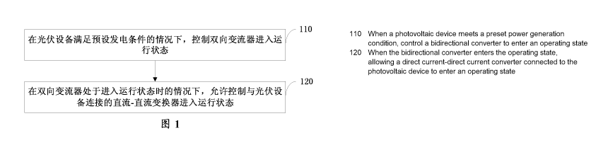
[0020] Fig. 1 is a schematic flow diagram of one embodiment of a
startup method of a photovoltaic air conditioning system of the
present disclosure;
[0021] Fig. 2 is a schematic structural diagram of one embodiment
of the photovoltaic air conditioning system of the present disclosure;
[0022] Fig. 3 is a schematic flow diagram illustrating another
embodiment of a startup method of the photovoltaic air conditioning
system according to the present disclosure;
[0023] Fig. 4 is a schematic flow diagram illustrating another
embodiment of a startup method of a photovoltaic air conditioning
system according to the present disclosure;
[0024] Fig. 5 is a schematic structural diagram of one embodiment
of the controller according to the present disclosure;
[0025] Fig. 6 is a schematic structural diagram of another embodiment
of the controller according to the present disclosure;
[0026] Fig. 7 is a schematic structural diagram of another embodiment
of the controller according to the present disclosure.
6
IEE200414PCA
Date recue / Date received 2021-11-09
CA 03139369 2021-11-09
DETAILED DESCRIPTION
[0027] Various exemplary embodiments of the present disclosure will
now be described in detail with reference to the accompanying
drawings. It should be noted that the relative arrangement of parts
and steps, numerical expressions and numerical values set forth in
these embodiments do not limit the scope of the present disclosure
unless specifically stated otherwise.
[0028] Meanwhile, it should be understood that the sizes of the
respective portions shown in the drawings are not drawn in an actual
proportional relationship for the convenience of description.
[0029] The following description of at least one exemplary embodiment
is merely illustrative in nature and is in no way intended to limit
the disclosure, its application, or uses.
[0030] Techniques, methods, and apparatus known to one of ordinary
skill in the relevant art may not be discussed in detail but are
intended to be part of the specification where appropriate.
[0031] In all examples shown and discussed herein, any particular
value should be construed as exemplary only and not as limiting. Thus,
other examples of the exemplary embodiments may have different values.
[0032] It should be noted that similar reference signs and letters
refer to similar items in the following figures, and thus, once an
item is defined in one figure, it need not be discussed further in
subsequent figures.
[0033] To make the objects, technical solutions and advantages of
the present disclosure more apparent, the present disclosure will
be described in further detail below with reference to specific
embodiments and the accompanying drawings.
[0034] The inventors of the present disclosure found through research
that an energy generated by photovoltaic device is greatly influenced
by the environmental climate and the connection load. In the related
art, the photovoltaic device is usually used as a power generation
source, and cannot effectively participate in the startup and
operation of the air conditioning system. When the air conditioning
system is started, a large amount of energy is instantaneously
7
IEE200414PCA
Date recue / Date received 2021-11-09
CA 03139369 2021-11-09
required. If the generated power of the photovoltaic device is smaller
than the power required by the air conditioner, the service life of
the photovoltaic device will be damaged, and negative effects can
be generated on the air conditioning system.
.. [0035] In view of the above, the present disclosure provides a startup
method of a photovoltaic air conditioning system, capable of improving
the stability of the system.
[0036] Fig. 1 is a schematic flow diagram of one embodiment of a
startup method of a photovoltaic air conditioning system of the
present disclosure. In some embodiments, the following startup method
is performed by a controller.
[0037] In step 110, a bidirectional inverter is controlled to enter
an operating state under a condition that a photovoltaic device meets
a preset power generation condition.
[0038] It should be noted here that an air conditioning system can
only be operated after the bidirectional inverter is started.
[0039] The bidirectional inverter can convert a direct current (DC)
into an alternating current (AC) and also can convert the alternating
current into the direct current.
[0040] Fig. 2 is a schematic structural view of one embodiment of
the photovoltaic air conditioning system of the present disclosure.
[0041] As shown in Fig. 2, the photovoltaic air conditioning system
includes a controller 210, a photovoltaic device 220, a DC-DC
converter 230, an outdoor unit 240 of the air conditioning device,
an indoor unit 250 of the air conditioning device, a bidirectional
inverter 260, and a DC bus 270.
[0042] The DC side includes a photovoltaic device 220, a DC-DC
converter 230, and other auxiliary circuits and structures. The
photovoltaic device 220 converts the output DC power into DC power
that can be transmitted on the DC bus 270 through the DC-DC converter
230, and sends electrical parameters to the controller 210. The
electrical parameters include the open circuit voltage and the
insulation impedance of the output of the photovoltaic device 220.
[0043] In some embodiments, the photovoltaic device 220 includes a
single-path photovoltaic string or a multi-path photovoltaic string.
8
IEE200414PCA
Date recue / Date received 2021-11-09
CA 03139369 2021-11-09
The DC-DC converter 230 is a single DC (Direct Current)/DC circuit,
and also be a circuit with a series or parallel function
correspondingly. The DC/DC circuit can be a BUCK conversion circuit
BUCK, a BOOST conversion circuit BOOST, a flyback circuit, a forward
circuit, a half-bridge circuit, a full-bridge circuit and other
topologies with the function of converting direct current into direct
current or the deformation of corresponding topology circuits.
[0044] In some embodiments, the voltage on the DC bus is a fixed DC
voltage, or a DC voltage that is within a voltage range.
[0045] The outdoor unit 240 of the air conditioning device receives
electric power from the DC bus 270 and transmits its own state to
the controller 210. The outdoor unit 240 of the air conditioning device
is in communication connection with the indoor unit 250 of the air
conditioner and the controller 210. In some embodiments, the
communication means includes CAN or RS485, etc. The indoor unit 250
of the air conditioning device receives power from the DC bus 270
or power from the AC power source 280 through the bidirectional
inverter 260, and transmits its own state to the controller 210. The
bidirectional inverter 260 is connected to a DC bus 270.
[0046] The AC side includes an AC power supply 280, a bidirectional
converter 260, and other auxiliary circuits and structures. In some
embodiments, AC power source 280 is an independent power generation
source, or a series-parallel combination of multiple power generation
sources or multiple power generation devices. The AC power supply
280 is capable of outputting AC power having a particular voltage
level and voltage frequency. In some embodiments, the AC power output
by AC power supply 280 may be a single phase power supply or a
multi-phase power supply. In some embodiments, the AC power source
280 is a respective power generation device, power supply device,
or energy storage device.
[0047] The bidirectional inverter 260 can convert power of the DC
bus into AC power, or convert AC power into power of the DC bus, and
in some embodiments, the bidirectional inverter 260 is a single-path
DC/AC (Alternating Current) circuit, or a circuit formed by connecting
multiple circuits with DC/AC functions in series or in parallel. In
9
IEE200414PCA
Date recue / Date received 2021-11-09
CA 03139369 2021-11-09
some embodiments, the bidirectional inverter 260 circuit is a circuit
with DC/AC function such as H bridge, H5, H6 and the like, and other
derivative topologies.
[0048] In step 120, the DC-DC converter connected to the photovoltaic
device is controlled to enter the operating state under a condition
that the bidirectional inverter enters the operating state. The
photovoltaic device can only supply electric power to the air
conditioning device through the DC-DC converter after the DC-DC
converter is operated.
[0049] In the startup method of the photovoltaic air conditioning
system provided by the embodiment of the present disclosure, the
bidirectional inverter is controlled to enter the operating state
under a condition that the photovoltaic device meets the preset power
generation condition, and then the DC-DC converter connected with
the photovoltaic device is controlled to enter the operating state,
so that the system stability is improved.
[0050] Fig. 3 is a schematic flow diagram illustrating another
embodiment of a startup method of the photovoltaic air conditioning
system according to the present disclosure. In some embodiments, the
following startup method is performed by a controller.
[0051] In step 310, the outdoor unit of the air conditioning device
enters a standby state after the photovoltaic air conditioning system
is connected to the mains supply. At this time, the bidirectional
inverter is in a non-operating state, and the indoor unit of the air
conditioning device is in a power-off state.
[0052] In step 320, it is determined whether the electrical parameter
of the photovoltaic device satisfies a predetermined power generation
condition. If the electrical parameters of the photovoltaic device
satisfies the predetermined power generation condition, step 330 is
executed. Otherwise, step 340 is performed.
[0053] In some embodiments, the electrical parameters include output
voltage and insulation impedance.
[0054] In some embodiments, it is determined that the photovoltaic
device satisfies the preset power generation condition under a
condition that the output voltage of the photovoltaic device is
IEE200414PCA
Date recue / Date received 2021-11-09
CA 03139369 2021-11-09
greater than the voltage threshold and the insulation impedance of
the photovoltaic device is greater than the impedance threshold.
Otherwise, it is determined that the photovoltaic device does not
meet the preset power generation condition. For example, when the
open-circuit voltage of the photovoltaic device is greater than or
equal to 120V and the insulation impedance detection is normal, the
photovoltaic device meets the preset power generation condition. The
insulation impedance detection is used for detecting whether the
insulation degree between the positive electrode and the negative
electrode of the output end of the photovoltaic device and the ground
is qualified or not.
[0055] In step 330, the bidirectional inverter is controlled to enter
the operating state.
[0056] It should be noted that the photovoltaic device is connected
to the bidirectional inverter through the DC-DC converter and the
DC bus.
[0057] In step 340, it is determined whether the indoor unit of the
air conditioning device receives a startup instruction. If the indoor
unit of the air conditioning device receives the startup instruction,
step 330 is executed. Otherwise, step 350 is performed.
[0058] In step 350, the bidirectional inverter is controlled to be
in a non-operating state. In this case, the air conditioning device
is connected to the bidirectional inverter via a DC bus.
[0059] Fig. 4 is a schematic flow diagram illustrating another
embodiment of a startup method of a photovoltaic air conditioning
system according to the present disclosure.
[0060] In step 410, an operation flag bit of the outdoor unit of the
air conditioning device, an operation flag bit of the bidirectional
inverter and an startup flag bit of the indoor unit of the air
conditioning device are all set to be 0 under a condition that the
outdoor unit of the air conditioning device is in a standby state.
[0061] In step 420, it is determined whether the photovoltaic device
satisfies a predetermined power generation condition. If the
photovoltaic device meets the preset power generation condition, step
11
IEE200414PCA
Date recue / Date received 2021-11-09
CA 03139369 2021-11-09
430 is performed. Otherwise, step 460 is performed.
[0062] In step 430, it is determined that the DC-DC converter
satisfies a preset startup condition. And setting a startup flag of
the DC-DC converter, namely setting the startup flag of the DC-DC
converter to 1.
[0063] In step 431, the bidirectional inverter is controlled to enter
the operating state. Namely, the operation flag bit of the
bidirectional inverter is set to 1. In some embodiments, the
controller sends a first control signal to the bidirectional inverter
to activate the bidirectional inverter.
[0064] In step 440, it is determined whether the bidirectional
inverter is in an operating state. If the bidirectional inverter is
in the operating state, steps 450 and 490 are respectively executed.
Otherwise, step 410 is performed.
[0065] The DC air conditioning device needs to obtain electric power
from a DC bus. Therefore, if the air conditioning device needs to
be put into an operating state, the bidirectional inverter must be
in an operating state. That is, the parameters of the photovoltaic
device indirectly affects the air conditioning device.
[0066] In step 450, it is determined whether the DC-DC converter
satisfies a predetermined startup condition. That is, it is detected
whether the startup flag of the DC-DC converter is 1. If the start
flag is 1, step 451 is executed, otherwise, step 410 is executed.
[0067] In step 451, the DC-DC converter is controlled to be in an
operating state. In some embodiments, the controller sends a second
control signal to the DC-DC converter to startup the DC-DC converter.
[0068] The DC-DC converter connected to the photovoltaic device is
allowed to operate, only when the bidirectional inverter connected
to the DC air conditioning device is in an operating state, i.e. the
relevant parameters of the air conditioning device functions in the
startup of the photovoltaic system.
[0069] In step 460, the DC-DC converter is not allowed to operate,
i.e., the startup flag of the DC-DC converter is set to 0.
[0070] In step 470, it is determined whether the indoor unit of the
air conditioning device receives a startup instruction. If the indoor
12
IEE200414PCA
Date recue / Date received 2021-11-09
CA 03139369 2021-11-09
unit of the air conditioner receives the startup instruction, step
480 is executed, otherwise, step 410 is executed.
[0071] In step 480, the indoor unit of the air conditioning device
is controlled to enter the power on state, and the startup flag of
the indoor unit of the air conditioning device is set to 1. Step 431
is subsequently performed.
[0072] In step 490, it is determined whether the indoor unit of the
air conditioning device is in an on state, that is, it is determined
whether the power on flag bit of the indoor unit of the air conditioning
device is 1. If the indoor unit of the air conditioning device is
in an on state, step 4100 is performed. Otherwise, step 410 is
performed.
[0073] In step 4100, the outdoor unit of the air conditioning device
is controlled to enter an operating state. Namely, the operation flag
bit of the outdoor unit of the air conditioning device is set to 1.
After indoor unit and the outdoor unit of the air conditioning device
are operated, if the user turns off the indoor unit, the step 470
is continuously performed subsequently.
[0074] In the embodiment, parameters related to the photovoltaic
device and parameters related to the air conditioning device are
correlated and interacted, so that the stability and the reliability
of the system are improved, and the service life of the system is
prolonged.
[0075] Fig. 5 is a schematic structural diagram of one embodiment
of the controller of the present disclosure. The controller includes
a bidirectional inverter control unit 510 and a DC-DC converter
control unit 520.
[0076] The bidirectional inverter control unit 510 is configured to
control the bidirectional inverter to enter an operating state when
the photovoltaic device satisfies a preset power generation
condition.
[0077] For example, when the outdoor unit of the air conditioning
device is in a standby state, the bidirectional inverter control unit
510 determines whether the electrical parameters of the photovoltaic
device meet a preset power generation condition. And if the electrical
13
IEE200414PCA
Date recue / Date received 2021-11-09
CA 03139369 2021-11-09
parameters of the photovoltaic device meet the preset power generation
conditions, a startup identifier of the DC-DC converter is set, and
the bidirectional inverter is controlled to enter an operating state.
If the electrical parameters of the photovoltaic device do not meet
the preset power generation condition, it is determined whether the
indoor unit of the air conditioning device receives a startup command.
And if the indoor unit of the air conditioning device receives the
startup command, the indoor unit of the air conditioning device is
controlled to enter an operating state and the bidirectional inverter
is controlled to enter the operating state.
[0078] In some embodiments, the bidirectional inverter control unit
510 sends a first control signal to the bidirectional inverter to
startup the bidirectional inverter.
[0079] The DC-DC converter control unit 520 is configured to control
the DC-DC converter connected to the photovoltaic device to enter
an operating state under a condition that the bidirectional inverter
enters the operating state, so that the photovoltaic device supplies
the electric power to the air conditioning device through the DC-DC
converter.
[0080] In the controller provided by the above embodiment of the
present disclosure, under the condition that the photovoltaic device
meets the preset power generation condition, the bidirectional
inverter is controlled to enter the operating state, and then the
DC-DC converter connected to the photovoltaic device is controlled
to enter the operating state, so that the system stability is improved.
[0081] Fig. 6 is a schematic structural diagram of another embodiment
of the controller of the present disclosure. The controller includes
a memory 610 and a processor 620, wherein the memory 610 may be a
magnetic disk, a flash memory, or any other non-volatile storage
medium. The memory is used for storing instructions in the embodiments
corresponding to Figs. 1, 3 and 4. The processor 620 is coupled to
memory 610, and may be implemented as one or more integrated circuits,
such as a microprocessor or a microcontroller. The processor 620 is
configured to execute instructions stored in the memory.
[0082] Fig. 7 is a schematic structural diagram of another embodiment
14
IEE200414PCA
Date recue / Date received 2021-11-09
CA 03139369 2021-11-09
of the controller of the present disclosure.
[0083] As shown in Fig. 7, the controller 700 includes a memory 710
and a processor 720. The processor 720 is coupled to the memory 710
by the BUS 730. The controller 700 may also be connected to an external
storage device 750 via a storage interface 740 for retrieving external
data, and may also be connected to a network or another computer system
(not shown) via a network interface 760, which will not be described
in detail herein.
[0084] In the embodiment, data instructions are stored by the memory
and processed by the processor, so that the stability of the system
is improved.
[0085] In further embodiments, a computer-readable storage medium
has stored thereon computer program instructions which, when executed
by a processor, implement the steps of the method in the embodiments
corresponding to Figs. 1, 3 and 4. As will be appreciated by those
skilled in the art, embodiments of the present disclosure may be
provided as a method, apparatus, or computer program product.
Accordingly, the present disclosure may take the form of an entirely
hardware embodiment, an entirely software embodiment or an embodiment
combining software and hardware aspects. Furthermore, the present
disclosure may take the form of a computer program product embodied
on one or more computer-usable non-transitory storage media
(including, but not limited to, disk storage, CD-ROM, optical storage,
and so forth) having computer-usable program code embodied therein.
[0086] The present disclosure is described with reference to
flowchart illustrations and/or block diagrams of methods, apparatus
(systems) and computer program products according to embodiments of
the disclosure. It will be understood that each flow and/or block
of the flowchart illustrations and/or block diagrams, and
combinations of flows and/or blocks in the flowchart illustrations
and/or block diagrams, can be implemented by computer program
instructions. These computer program instructions may be provided
to a processor of a general purpose computer, special purpose
computer, embedded processor, or other programmable data processing
apparatus to produce a machine, such that the instructions, which
IEE200414PCA
Date recue / Date received 202 1-1 1-09
CA 03139369 2021-11-09
execute via the processor of the computer or other programmable data
processing apparatus, create means for implementing the functions
specified in the flowchart flow or flows and/or block diagram block
or blocks.
[0087] These computer program instructions may also be stored in a
computer-readable memory that can direct a computer or other
programmable data processing apparatus to function in a particular
manner, such that the instructions stored in the computer-readable
memory produce an article of manufacture including instruction means
which implement the function specified in the flowchart flow or flows
and/or block diagram block or blocks.
[0088] These computer program instructions may also be loaded onto
a computer or other programmable data processing apparatus to cause
a series of operational steps to be performed on the computer or other
programmable apparatus to produce a computer implemented process such
that the instructions which execute on the computer or other
programmable apparatus provide steps for implementing the functions
specified in the flowchart flow or flows and/or block diagram block
or blocks.
[0089] Thus far, the present disclosure has been described in detail.
Some details well known in the art have not been described in order
to avoid obscuring the concepts of the present disclosure. Those
skilled in the art can now fully appreciate how to implement the
teachings disclosed herein, in view of the foregoing description.
[0090] Although some specific embodiments of the present disclosure
have been described in detail by way of example, it should be
understood by those skilled in the art that the above examples are
for illustration only and are not intended to limit the scope of the
present disclosure. It will be appreciated by those skilled in the
art that modifications can be made to the above embodiments without
departing from the scope and spirit of the present disclosure. The
scope of the present disclosure is defined by the appended claims.
16
IEE200414PCA
Date recue / Date received 2021-11-09