Note: Descriptions are shown in the official language in which they were submitted.
SPEED NUT
BACKGROUND OF THE INVENTION
[0001] The present invention relates generally to speed nuts for rapid
attachment to a
threaded rod and subsequent use as a conventional nut, and in particular to a
speed nut suitable
for use in high-force valve extraction applications and the like.
[0002] Pumps used for the pumping of fluid used in oil and natural gas
extraction operations
may include valve seats that wear over time and must be replaced. These valve
seats are usually
press fit into a casting or the like and must be pulled free from within the
casting using
considerable force, for example, obtained through a hydraulic cylinder.
[0003] Valve seat pullers are known which can extend into a casting and
pass through a
valve seat to extract the valve seat. The pullers include jaws with outwardly
extending teeth for
engaging a backside of the valve seat and providing a threaded shaft attached
to the puller which
can extend out of the casting. The threaded shaft outside of the casting
passes through a
hydraulic pancake jack and then is received by a nut that may be threaded down
along the
threaded shaft to tighten against the outer surface of the pancake jack so
that the pancake jack
can provide the necessary high forces to the threaded shaft and ultimately to
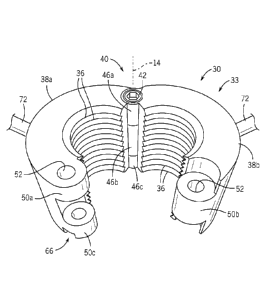
the valve seat. A
valve seat puller of this design is taught by US patent 10,639,752 assigned to
the assignee of the
present invention.
[0004] The threaded shaft is given threads with a shallow pitch to improve
resistance to axial
force but with the drawback of requiring many turns of the nut to move the nut
the length of the
threaded shaft to tighten against the pancake jack. The time required for this
operation can delay
the replacement of critical valve components.
SUMMARY OF THE INVENTION
[0005] The present invention is a speed nut that can be rapidly attached to
a point on the
threaded shaft close to the pancake jack by separating the portions of the
nut, positioning the nut,
then clamping the portions of the nut about the threaded rod to be tightened
in a conventional
fashion. A "dual-knuckle" design allows rapid locking of the nut halves
together to resist axial
force using an axially-extending pin easily removed in the field and providing
precise location of
the nut halves' separation.
[0006] Specifically then, the present invention provides a speed nut having
a first and second
1
Date Recue/Date Received 2021-11-17
portion movable between a separated position and a closed position. In the
closed position, the
first and second portions abut to define an internally threaded cylindrical
cavity extending along
an axis and sized to receive and engage a corresponding threaded shaft for
threaded rotation
therethrough. The speed nut also includes at least one torsion arm having a
proximal end
attached to the housing and a distal end extending away from the axis to allow
rotation of the
housing about the threaded shaft when the first and second portions are in the
closed position.
[0007] Each of the first and second portions provide outwardly extending
knuckles at
laterally opposed edges so that when the first and second portions are in the
closed position, the
knuckles of laterally opposed edges of the first portion interdigitate with
the knuckles of the
laterally opposed edges of the second portion to resist relative axial motion
between the first and
second portions.
[0008] It is thus a feature of at least one embodiment of the invention to
provide a speed nut
that can be rapidly positioned on a threaded rod and yet can provide high
forces on that threaded
rod. Resulting forces of axial displacement between the nut halves are
resisted by mutual
engagement of the knuckles which may nevertheless freely separate when the
force is removed.
[0009] The knuckles may include bores along bore-axes parallel to the axis
that align when
the first and second portions are in the closed position. The bores may
receive respective first
and second pins to hold the first and second portions in the closed position.
[0010] It is thus a feature of at least one embodiment of the invention to
provide a simple
way of holding the speed nut in the closed position against forces of
separation that may occur
during use of the torsion handle. Again, the pins may be freely inserted and
removed in a state
of no torsion but robustly resist separation of the speed nut portions under
torsion.
[0011] The knuckles receiving the first pin may be adapted to allow a
hinging motion around
the bore-axis of the first pin to move the first and second portions between
the open and closed
positions.
[0012] It is thus a feature of at least one embodiment of the invention to
provide a simple
method of allowing the first and second portions to be separated or closed
while retaining
alignment to prevent thread damage and to prevent full separation where the
portions could be
lost or damaged.
[0013] The first pin may provide a threaded end received by corresponding
threads in at least
one receiving knuckle to retain the first pin in the bore against pivoting
motion of the first and
2
Date Recue/Date Received 2021-11-17
second portions.
[0014] It is thus a feature of at least one embodiment of the invention to
ensure retention of
the hinge pin against sliding out from the knuckles while allowing disassembly
for cleaning and
the like.
[0015] The first pin when received by the knuckles may expose an end
adapted to receive a
driving tool for rotation of the first pin.
[0016] It is thus a feature of at least one embodiment of the invention to
allow simple
disassembly of the hinge pin without the need for impact, for example from a
pin punch or the
like, such as could damage the pin or it's receiving bore.
[0017] The second pin may include a spring detent releasably engaging the
second pin with
the knuckles receiving the second pin. In some embodiments, the spring detent
may be a spring-
loaded ball held captive in an end of the second pin to retract with motion of
the end through a
receiving bore of the knuckles and to extend outwardly at an opening from the
receiving bore
when the second pin is fully engaged in the receiving bore.
[0018] It is thus a feature of at least one embodiment of the invention to
provide a simple
method of retaining the speed nut in its closed position that is resistant
from high forces of
torsional separation and yet which allows rapid repositioning of the nut as
desired. The detent
system allows rapid installation and removal of the second pin without special
tools and yet
retention of the second pin against incidental forces of vibration and the
like.
[0019] The second pin may further include a grip pivotally attached to an
end of the second
pin to be graspable when the second pin is fully engaged within the receiving
bore for extraction
of the second pin.
[0020] It is thus a feature of at least one embodiment of the invention to
allow use of the
speed nut in the field without special tools and provide an ample gripping
surface without
interference between the grip and the threaded rod by pivoting.
[0021] The speed nut may include two torsion arms each having a proximal
end attached to a
different one of the first and second portions and each having a distal end
extending outward
from the housing with radial symmetry about the axis.
[0022] It is thus a feature of at least one embodiment of the invention to
allow high torsions
to be applied to the speed nut in a balanced fashion while also resisting
axial displacement of the
speed nut portions.
3
Date Recue/Date Received 2021-11-17
[0023] The first and second portions may each be machined solid steel.
[0024] It is thus a feature of at least one embodiment of the invention to
provide a design that
can be fabricated without welds or seams that can create failure points.
[0025] These particular objects and advantages may apply to only some
embodiments falling
within the claims and thus do not define the scope of the invention.
BRIEF DESCRIPTION OF THE DRAWINGS
[0026] Fig. 1 is a simplified front, elevational cross-section of a valve
having a valve seat
showing positioning of a valve seat puller for removal of the valve seat, the
valve seat
communicating by means of the threaded shaft with a pancake hydraulic unit and
speed nut of
the present invention;
[0027] Fig. 2 is a side elevational fragmentary view of the speed nut
showing the axial
locking pin and its detent mechanism.
[0028] Fig. 3 is a top, fragmentary plan view of the speed nut showing the
dual knuckle
design that provides rapid separation of the nut halves and precise assembly
around the threaded
shaft;
[0029] Fig. 4 is a perspective view of the nut opened for rapid adjustment
to different
locations on the threaded shaft of Fig. 1; and
[0030] Fig. 5 is a perspective view of one half of the speed nut better
showing the knuckle
arrangement.
DETAILED DESCRIPTION OF THE PREFERRED EMBODIMENT
[0031] Referring now to Fig. 1, a valve seat puller 10 suitable for use
with the present
invention may include a threaded shaft 12 extending along the insertion axis
14 and attached at
its lower end to a seat puller body 16 by a threaded coupling thereto.
Extending from beneath
the seat puller body 16 are first and second jaws 18a and 18b attached at
their upper ends to the
seat puller body 16 to be retained axially with respect to the seat puller
body 16. Lower ends of
the first and second jaws 18 hold at their lower tips outwardly extending
ledges 22. The lower
ends of the first and second jaws 18 may pivot with respect to each other
inward and outward as
indicated by arrows 20 to pass through a ring-shaped valve seat 24 and to
extend on the other
side of the valve seat 24 so that the ledges 22 can grip a backside 26 of the
valve seat 24 to allow
it to be extracted.
4
Date Recue/Date Received 2021-11-17
[0032] A speed nut 30 of the present invention may be threaded onto the
upper end of the
threaded shaft 12 to support the threaded shaft 12 against a pancake hydraulic
cylinder 32
allowing substantial forces to be applied by the pancake hydraulic cylinder 32
to the seat puller
along axis 14 against a body of the valve or pump casting 15.
[0033] Referring now to Figs. 2-5, the speed nut 30 may, in a closed state
as shown in Figs. 1
and 3, provide for a generally cylindrical body 33 having an axial central
bore 34 with internal
threads 36 that may engage external threads 37 of the threaded shaft 12. The
body 33 is
composed of two halves 38a and 38 separated generally along a plane aligned
with axis 14 to
divide the body 33 into approximately equal halves. The halves 38a and 38b
join at first vertical
edges by a hinge 40 pivoting about a hinge pin 42 having an axis 44 offset but
parallel to axis 14.
The hinge 40 may provide for a set of vertically stacked knuckles 46a-46c
arranged in the
manner of a conventional door hinge with each knuckle 46 providing a generally
cylindrical tube
receiving the hinge pin 42 therethrough and the knuckles 46a-46c having
sequentially abutting
cylindrical bases with knuckles 46a and 46c being integrally formed with half
38a and flanking
knuckles 46b being integrally formed with half 38b so that the two halves 38a
and 38b may
separate, pivoting about the axis 14 and yet be retained against relative
axial movement by the
inter-engagement of the knuckles 46.
[0034] The opposite vertical edges of the halves 38a and 38b which may
pivot toward and
away from each other, in a closed state, may be retained by inter-engaging
knuckles 50a-50c,
also arranged (when the halves 38a and 38b are close together) in a vertical
stack with knuckles
50a and 50c being integral with half 38a and flanking knuckle 50b, the latter
integrated with half
38b respectively. In the closed state, these knuckles 50 like knuckles 46
provide stacked
interdigitated cylindrical tubes that resist axial movement of the halves 38
with respect to each
other and provide central bores 52 which align in the closed state with the
proper clearance
between the threads 36. The central bores 52 may be retained in closed
alignment by a quick
release pin 56 (shown in Figs 1 and 4) threaded through the bores 52 now
aligned along axis 57
parallel to but displaced from axis 14 and diametrically opposed to axis 44.
[0035] The quick release pin 56 may have a head portion 58 receiving a ring
60 that may be
engaged by a user's fingers to release the pin 56 pulling it upwardly along
axis 57. A bottom
portion of the pin 56 may support a spring-loaded detent ball 62 engaging a
lower lip 64 of
knuckle 50c, for example, formed by a cut out 66 so that the end of the pin 56
terminates above a
5
Date Recue/Date Received 2021-11-17
surface 70 of the nut 30 engaging the hydraulic pancake cylinder 32 while
retaining the quick
release pin 56 in position against minor vibration and the like.
[0036] Referring to Figs. 1-4, optional, diametrically extending handles 72
may be welded or
screwed in corresponding bores into the outer surfaces of the collars' halves
38a and 38b to assist
in rotating the nut 30 and in separating the halves along the hinge axis 14 as
desired for
relocation. In this regard, it will be appreciated that the hinge 40 may be
moved to the open state
shown in Fig. 3 and quickly positioned along the axial direction over the
threaded shaft 12 and
then closed together, pivoting about the hinge 40, and held in the closed
position by the quick
release pin 56 inserted through the bores 52 in the knuckles 50 now in
alignment. Rotation of
the nut 30 using the handles 72 may then be accomplished in the manner of a
conventional nut.
[0037] As shown in Fig. 4, the hinge pin 42 may be threaded at its lower
end to engage
corresponding internal threads 80 into knuckle 46c and may, for example,
provide a hex cap
screw head that is countersunk into knuckle 46a.
[0038] Generally the nut 30 will be made of a high quality steel or the
like with the elements
of halves 38a and 38b machined from respective single blocks of a steel
element for high
strength. The knuckles 46 and 50 may be outset from the threads 36 so that the
threads 36
provide a continuous helix within the closed nut 30.
[0039] It is specifically intended that the present invention nut be
limited to the embodiments
and illustrations contained herein and the claims should be understood to
include modified forms
of those embodiments including portions of the embodiments and combinations of
elements of
different embodiments as come within the scope of the following claims.
6
Date Recue/Date Received 2021-11-17