Note: Descriptions are shown in the official language in which they were submitted.
SHOCK ABSORBER FOR A VEHICLE
CROSS-REFERENCE
[0001] The present application claims priority to United States
Provisional Patent Application
No. 63/118,685, entitled "Shock Absorber for a Vehicle", filed November 26,
2020.
FIELD OF TECHNOLOGY
[0002] The present technology relates to shock absorbers and shock
absorber assemblies for
vehicles.
BACKGROUND
[0003] There exist various types of vehicles used mainly in off-road
conditions. One such type
is the side-by-side off-road vehicle. The name "side-by-side" refers to the
seating arrangement of
the vehicle in which the driver and a passenger are seated side-by-side. Some
side-by-side off-
road vehicles also have a second row of seats to accommodate one or more
additional passengers.
[0004] To be able to operate in off-road conditions, an off-road
vehicle, such as a side-by-side
or a snowmobile, needs to be able to handle various surfaces including, but
not limited to, sand,
dirt, snow, and mud. These conditions represent unique challenges not
typically encountered when
designing on-road vehicles such as a car.
[0005] One such challenge is that varying road conditions can mean that
one stiffness of the
suspension assemblies, including the associated shock absorbers, could be
preferable for handling
the terrain at one moment, but due to a sudden change in terrain, a different
suspension and shock
absorber stiffness may be preferable at the next moment.
[0006] Thus, there is a desire for a shock absorber suitable for the
operating conditions of side-
by-side off-road vehicles.
SUMMARY
[0007] It is an object of the present technology to ameliorate at least
some of the inconveniences
present in the prior art.
Date Recue/Date Received 2021-11-19
[0008] According to an aspect of the present technology, there is
provided a shock absorber
(and shock absorber assembly including the shock absorber) with adjustable
compression stiffness,
the shock absorber being adjustable as fully-assembled and/or while installed
on a vehicle. The
shock absorber includes a reservoir base valve defining passages through which
hydraulic fluid
passes when the shock absorber is compressed or is rebounding (expending). The
shock absorber
also defines a bypass channel, flow of hydraulic fluid through which is
controlled by a bypass
valve. Inclusion of a check valve in the bypass channel impedes reverse flow
of the hydraulic fluid
when the shock is rebounding, such that only the compression stiffness is
adjustable, and the shock
absorber will also rebound at a same rate. The bypass valve is configured to
fully close the channel
(limiting the flow of hydraulic fluid to the compression passages in the
reservoir base valve) or
open the channel (allowing the hydraulic fluid to flow through the channel in
addition to the
compression passages in the reservoir base valve). In some cases, the valve
could also partially
block the channel, allowing hydraulic fluid to flow through at a lower flux
than when the channel
is fully open. By controlling the flow of hydraulic fluid through the bypass
channel during
compression, the compression stiffness of the shock absorber can be adjusted
without the need for
tools or disassembly of the shock absorber, thereby rendering it possible to
adjust compression
stiffness of the shock absorber during operation of the vehicle to which it is
installed.
[0009] According to one aspect of the present technology, there is
provided a shock absorber
including a cylinder having a first end and a second end, a piston rod
extending through the first
end of the cylinder, a cylinder piston disposed in the cylinder, the cylinder
piston being connected
to an end of the piston rod; a reservoir fluidly connected to the second end
of the cylinder, the
reservoir and the cylinder defining a fluid chamber for receiving a hydraulic
fluid, a reservoir base
valve disposed in the fluid chamber, the reservoir base valve separating the
fluid chamber into a
first portion and a second portion, the reservoir base valve defining a
plurality of passages fluidly
connecting the first portion and the second portion, the plurality of passages
including at least one
compression passage and at least one rebound passage; a bypass channel fluidly
connecting the
first portion of the fluid chamber to the second portion of the fluid chamber;
a bypass valve
disposed in the fluid chamber, the bypass valve being configured to
selectively control fluid flow
through the bypass channel, the bypass valve being selectively movable between
at least an open
position and a closed position; and a check valve disposed in the bypass
passage, the check valve
being configured to: permit fluid flow through the bypass channel from the
first portion to the
Date Recue/Date Received 2021-11-19
second portion, and impede fluid flow through the bypass channel from the
second portion to the
first portion.
[0010] In some implementations, the shock absorber further includes the
hydraulic fluid
contained in the cylinder and the reservoir; and wherein: when the bypass
valve is in the closed
position: fluid flows through the at least one compression passage, from the
first portion to the
second portion, when the shock absorber is compressing, and fluid flows
through the at least one
rebound passage, from the second portion to the first portion, when the shock
absorber is
expanding; and when the bypass valve is in the open position: fluid flows
through by bypass
channel and/or the at least one compression passage, from the first portion to
the second portion,
when the shock absorber is compressing, and fluid flows through the at least
one rebound passage,
from the second portion to the first portion, when the shock absorber is
expanding, the check valve
impeding flow of the fluid from the second portion to the first portion.
[0011] In some implementations, the bypass valve includes a solenoid for
controlling
movement of the bypass valve.
[0012] In some implementations, the shock absorber further includes a
separator disposed in
the reservoir, the separator being configured to separate fluid in the
reservoir from a compressed
gas in the reservoir, the separator adapted to increase or decrease the volume
of fluid within the
reservoir.
[0013] In some implementations, the separator is a bladder.
[0014] In some implementations, the reservoir is offset from a longitudinal
axis passing through
a center of the cylinder.
[0015] In some implementations, the shock absorber further includes a
reservoir conduit fluidly
connecting the cylinder to the reservoir.
[0016] In some implementations, the reservoir base valve is disposed in
the reservoir; and the
bypass valve is disposed in the reservoir.
[0017] In some implementations, the bypass channel is formed by the
reservoir base valve.
Date Recue/Date Received 2021-11-19
[0018] In some implementations, the bypass channel is formed by walls of
the reservoir.
[0019] In some implementations, the bypass valve defines the bypass
channel therethrough
[0020] According to another aspect of the present technology, there is
provided a shock
absorber assembly, including a shock absorber including: a cylinder having a
first end and a second
end, a piston rod extending through the first end of the cylinder, a cylinder
piston disposed in the
cylinder, the cylinder piston being connected to an end of the piston rod; a
reservoir fluidly
connected to the second end of the cylinder, the reservoir and the cylinder
defining a fluid chamber
for receiving a hydraulic fluid, a reservoir base valve disposed in the fluid
chamber, the reservoir
base valve separating the fluid chamber into a first portion and a second
portion, the reservoir base
valve defining a plurality of passages fluidly connecting the first portion
and the second portion,
the plurality of passages including at least one compression passage and at
least one rebound
passage; a bypass channel fluidly connecting the first portion of the fluid
chamber to the second
portion of the fluid chamber; a bypass valve disposed in the fluid chamber,
the bypass valve being
configured to selectively control fluid flow through the bypass channel, the
bypass valve being
selectively movable between at least an open position and a closed position;
and a check valve
within the bypass passage, the check valve being configured to: permit fluid
flow through the
bypass channel from the first portion to the second portion, and impede fluid
flow through the
bypass channel from the second portion to the first portion; and a coil
disposed around the cylinder
of the shock absorber.
[0021] Implementations of the present technology each have at least one of
the above-
mentioned object and/or aspects, but do not necessarily have all of them. It
should be understood
that some aspects of the present technology that have resulted from attempting
to attain the above-
mentioned object may not satisfy this object and/or may satisfy other objects
not specifically
recited herein.
[0022] Additional and/or alternative features, aspects and advantages of
implementations of the
present technology will become apparent from the following description, the
accompanying
drawings and the appended claims.
Date Recue/Date Received 2021-11-19
BRIEF DESCRIPTION OF THE DRAWINGS
[0023] For a better understanding of the present technology, as well as
other aspects and further
features thereof, reference is made to the following description which is to
be used in conjunction
with the accompanying drawings, where:
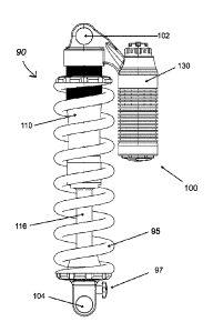
[0024] Figure 1 is a front elevation view of a shock absorber assembly;
[0025] Figure 2A is a cross-sectional view of the shock absorber
assembly of Figure 1, with a
channel valve and a check valve being in a closed position;
[0026] Figure 2B is the cross-sectional view of the shock absorber of
Figure 2A, with the
channel valve and the check valve being in the closed position and the shock
absorber being in a
compressed configuration;
[0027] Figure 3 is the cross-sectional view of the shock absorber of
Figure 2A, with the channel
valve and the check valve being in an open position;
[0028] Figure 4 is the cross-sectional view of the shock absorber of
Figure 2A, with the channel
valve in the open position and the check valve being in the closed position;
[0029] Figure 5 is a close-up, partial, cross-sectional view of a reservoir
of the shock absorber
assembly of Figure 1, with the channel valve and the check valve being in the
opened position;
[0030] Figure 6 is a close-up, partial view of the cross-sectional view
of Figure 4;
[0031] Figure 7 is a close-up, partial view of the cross-sectional view
of Figure 5;
[0032] Figure 8 is a cross-sectional view of another implementation of a
shock absorber
assembly; and
[0033] Figure 9 is a schematic diagram of flow managing components of
the shock absorber of
Figure 1.
[0034] It should be noted that the Figures may not be drawn to scale,
unless otherwise indicated.
Date Recue/Date Received 2021-11-19
DETAILED DESCRIPTION
[0035] A shock absorber assembly 90 according to the present technology
is described with
reference to Figures 1 to 4. It should be noted that the directions top and
bottom are assigned to
the shock absorber assembly 90 as illustrated for ease of reference, but do
not necessarily
.. correspond to the relative orientation of the shock absorber assembly 90 as
it would be installed
on a vehicle.
[0036] The shock absorber assembly 90 includes a shock absorber 100. The
shock absorber
assembly 90 also includes a coil spring 95 disposed round the shock absorber
100. The coil spring
95 aids in returning the shock absorber 100 to an extended position after the
shock absorber 100
has been compressed during use.
[0037] The shock absorber 100 includes a cylinder 110 for containing
hydraulic fluid. The
cylinder 110 has a bottom end 112 and a top end 114. A longitudinal axis 111
extends through a
center of the cylinder 110, through the bottom and top ends 112, 114.
[0038] The shock absorber 100 includes a piston rod 116 extending
through the bottom end
.. 112 of the cylinder 110. The piston rod 116 is generally aligned with the
longitudinal axis 111.
The shock absorber 100 also includes a cylinder piston 118 disposed in the
cylinder 110. The
cylinder piston 118 includes at least two passages 119 through which some
hydraulic fluid passes
when the piston 118 moves through the cylinder 110. The cylinder piston 118 is
connected to an
end of the piston rod 116 disposed in the cylinder 110, the other end of the
piston rod 116 being
disposed outside the cylinder 110.
[0039] The shock absorber 100 includes two apertures, a top aperture 102
and a bottom aperture
104, for connecting the shock absorber 100 (and the shock absorber assembly
90) to a vehicle. In
some implementations, the apertures 102, 104 could be replaced with different
fixtures for
mounting the shock absorber 100. The shock absorber 100 also includes an
adjustment bolt 97 for
adjusting damping characteristics of the piston 118.
[0040] The shock absorber 100 includes a reservoir 130 fluidly connected
to the top end 114
of the cylinder 110. It is contemplated that the reservoir 130 could be
connected to a different point
of the cylinder 110. In the illustrated implementation, the reservoir 130 is
an external reservoir
Date Recue/Date Received 2021-11-19
130, where the reservoir 130 is offset from the longitudinal axis 111. It is
contemplated that in
some implementations the shock absorber 100 could include an inline reservoir,
where the
reservoir is disposed above the cylinder 110 and generally aligned with the
axis 111.
[0041] The cylinder 110 and the reservoir 130 together define a fluid
chamber 120 for receiving
the hydraulic fluid in the shock absorber 100. In the present implementation,
the fluid chamber
120 includes a reservoir conduit 125 that fluidly connects the portion of the
fluid chamber 120
defined by the cylinder 110 to the portion of the fluid chamber 120 defined by
the reservoir 130.
[0042] The shock absorber 100 further includes a separator 132 disposed
in the reservoir 130.
The separator 132 is configured and arranged to separate the hydraulic fluid
in the reservoir 130
from a compressed gas in the reservoir 130. The separator 132 defines a gas
chamber 134 in which
gas is contained. As such, the separator 132 determines, in part, the volume
of hydraulic fluid
received in the fluid chamber 120 during installation. During use of the shock
absorber assembly
90, the separator 132 is partially compressed to allow upward movement of the
piston 118 during
compression of the shock absorber 100. According to the illustrated
implementation, the separator
132 is a bladder 132. In some implementations, the separator 132 could instead
be a floating piston.
It is also contemplated that the separator 132 and the gas chamber 134 could
be replaced with a
different compressible system, such as a piston and spring.
[0043] The shock absorber 100 includes a reservoir base valve 140
disposed in the fluid
chamber 120. The reservoir base valve 140 is disposed specifically in the
reservoir 130 in the
illustrated implementation. It is contemplated that the base valve 140 could
be located in the
cylinder 110 in some implementations. The reservoir base valve 140 separates
the fluid chamber
120 into a first portion 142, including a portion of the fluid chamber 120
defined by the cylinder
110, and a second portion 144 between the base valve 140 and the separator
132.
[0044] The base valve 140 defines a plurality of passages therein,
through which hydraulic fluid
passes when the shock absorber 100 is compresses or rebounds (expands). When
the shock
absorber 100 is compressed (see Figure 2B), which is defined by the piston 118
moving upward
into the cylinder 110, there is less volume available to the hydraulic fluid
in the cylinder 110 and
thus a portion of the hydraulic fluid is pushed into the reservoir 130 and
through compression
passages 143 defined in the base valve 140. Specifically, some of the
hydraulic fluid flows from
Date Recue/Date Received 2021-11-19
the first portion 142 of the fluid chamber 120 to the second portion 144 via
the compression
passages 143. Similarly, when the shock absorber 100 rebounds (see Figure 2A),
which is defined
by the piston 118 moving downward toward the bottom end 112 of the cylinder
110, there is
additional volume available for hydraulic fluid in the cylinder 110 and a
portion of the hydraulic
fluid flows through rebound passages 145 defined in the base valve 140, from
the second portion
144 toward the first portion 142, back toward the cylinder 110.
[0045] The compression and rebound passages 143, 145 are formed in part
by shims that allow
flow fluid to flow through the passages 143, 145 in a single direction, such
that fluid does not flow
through the compression passages 143 when the shock absorber 100 is rebounding
and the fluid
does not flow through the rebound passages 145 when the shock absorber 100 is
compressing. In
some implementations, it is contemplated that the base valve 140 could define
one compression
passage and one rebound passage, or many compression and rebound passages. It
is also
contemplated that the passages 143, 145 could be differently formed.
[0046] With additional reference to Figure 5, the shock absorber 100
further includes a bypass
channel 160 fluidly connecting the first portion 142 of the fluid chamber 120
to the second portion
144 of the fluid chamber 120. In the implementation illustrated in Figures 1
to 5, the bypass
channel 160 is formed through the base valve 140.
[0047] The shock absorber 100 further includes a bypass valve 164
disposed in the fluid
chamber 120. The bypass valve 164 defines at least in part the bypass channel
160. The bypass
valve 164 is configured to selectively control flow of hydraulic fluid from
the first portion 142 to
the second portion 144 through the bypass channel 160, by selectively closing
and opening the
bypass channel 160. In the illustrated implementation, the bypass valve 164
includes a needle-
shaped piston 166 and a plate 168, with a hole defined therein, transecting
the channel 160. When
the end of the needle-shaped piston 166 abuts the plate 168, in a closed
position of the bypass
valve 164, the channel 160 is obstructed and the hydraulic fluid cannot flow
through the bypass
channel 160. The bypass valve 164 is illustrated in the closed position in
Figures 2A and 2B. When
the needle-shaped piston 166 is distanced from the plate 168, in an open
position of the bypass
valve 164, the hydraulic fluid can pass through the hole in the plate 168,
allowing hydraulic fluid
Date Recue/Date Received 2021-11-19
to flow through the bypass channel 160. The bypass valve 164 is illustrated in
the open position in
Figures 3 to 5.
[0048] In some implementations, the bypass valve 164 could additionally
be positionable in
one or more intermediary position between the open position and the closed
position, wherein the
needle-shaped piston 166 is near but not fully engaged with the plate 168. In
such a case, the flow
of hydraulic fluid through the channel 160 could be partially impeded, but not
fully obstructed, in
order to limit flow through the channel 160.
[0049] The bypass valve 164 includes a solenoid 170 to control movement
of the needle-shaped
piston 166 between the open, closed, and intermediary positions. Depending on
the
implementation, the bypass valve 164 could instead include a different
transducer or actuator for
controlling movement of the needle-shaped piston 166. The solenoid 170 is
communicatively
connected to a controller 101 (shown schematically in Figure 5) for
controlling the positioning of
the valve 164. In some embodiments, other actuator technologies could be used
to control
positioning of the valve 164, including but not limited to stepper-motors. It
is contemplated that
the solenoid 170, or other actuator controlling positioning of the valve 164,
could be alternatively
or additionally controlled by inputs disposed on the shock absorber assembly
90. In some
implementations, the bypass valve 164 could be controlled by a different
mechanism than the
solenoid 170. For example, the shock absorber assembly 90 could include
buttons, switches, or
dials for controlling the valve 164.
[0050] The shock absorber 100 further includes a check valve 172 to control
directionality of
the bypass channel 160. The check valve 172 is disposed in the bypass channel
160, specifically
at an end of the channel 160 open to the second portion 144 of the fluid
chamber 120. In the
illustrated implementation, the check valve 172 is specifically a ball check
valve 172, but it is
contemplated that different types of check valves could be used. The check
valve 172 is arranged
to permit fluid flow through the bypass channel 160 from the first portion 142
of the fluid chamber
120 to the second portion 144 of the fluid chamber 120 and to impede fluid
flow through the bypass
channel 160 from the second portion 144 to the first portion 142.
[0051] In the case of the ball check valve 172, flow of the hydraulic
fluid from the first portion
142 toward the second portion 144 pushes a ball 174 of the ball check valve
172 downward, into
Date Recue/Date Received 2021-11-19
an open position, to open passages 173 in the valve 164 opening the channel
160 to the second
portion 144 of the fluid chamber 120. The check valve 172 is illustrated in
the open position in
Figures 3 and 5, with fluid flow schematically illustrated in Figure 7. During
rebound, when
hydraulic fluid flows from the second portion 144 to the first portion 142 of
the fluid chamber 120,
the ball 174 is forced upward where it blocks the passages 173 thereby closing
the bypass channel
160 and preventing reverse flow of hydraulic fluid from the second portion 144
of the fluid
chamber 120 to the first portion 142 of the fluid chamber 120 through the
channel 160. Fluid flow
during rebound is illustrated schematically in Figure 6. The sequential
arrangement of the different
flow managing components, specifically the piston 118 with the passages 119,
the base valve 140,
the bypass valve 164, the check valve 172, and the chamber 134, is further
schematically illustrated
in Figure 9.
[0052] When the shock absorber assembly 90 is in use, for example when
installed on a vehicle,
the resistance to fluid flow through the reservoir base valve 140 during
compression and rebound
at least partially determines the stiffness of the shock absorber 100. During
assembly of the shock
absorber 100, the resistance can be calibrated by adjusting the number and
arrangement of the
shims forming the compression and rebound passages 143, 145 and the volume of
gas in the
chamber 134. Once fully assembled, however, the compression and rebound
passages 143, 145
and the gas in the chamber 134 cannot be adjusted. According to the present
technology,
compression rigidity of the shock absorber 100 can be adjusted while fully
assembled and/or
during use, however, through use of the bypass valve 164 and the bypass
channel 160.
[0053] When the bypass valve 164 is in the closed position, the
hydraulic fluid flows through
the compression passages 143, from the first portion 142 to the second portion
144, when the shock
absorber 100 is compressing. When the shock absorber 100 is expanding during
rebound, the
hydraulic fluid flows through the rebound passages 145, from the second
portion 144 to the first
portion 142.
[0054] When the bypass valve 164 is in the open position, the hydraulic
fluid flows through the
bypass channel 160 and the compression passages 143, from the first portion
142 to the second
portion 144, when the shock absorber 100 is compressing. By allowing the
hydraulic fluid to pass
through both the channel 160 and the compression passage 143, the shock
absorber 100 will
Date Recue/Date Received 2021-11-19
compress more easily and thus be less stiff (relative to the stiffness when
the valve 164 is closed).
When the shock absorber 100 is expanding during rebound, the hydraulic fluid
flows through the
rebound passages 145, from the second portion 144 to the first portion 142,
the check valve 172
impeding flow of the fluid from the second portion 144 to the first portion
142.
[0055] Another implementation of a shock absorber assembly 200 according to
the present
technology is illustrated in Figure 8. Elements of the shock absorber assembly
200 that are similar
to those of the shock absorber assembly 90 retain the same reference numeral
and will generally
not be described again.
[0056] The shock absorber assembly 200 includes a shock absorber 210
including the cylinder
110 and a reservoir 230. A base valve 240 is disposed in the fluid chamber
120, specifically in the
reservoir 230. The base valve 240 includes the compression and rebound
passages 143, 145. The
reservoir 230 also includes a bypass channel 260 defined by walls of the
reservoir 230. In this
implementation, the bypass channel 260 does not pass through the base valve
240.
[0057] The shock absorber 210 also includes a bypass valve 264 for
controlling flow of
hydraulic fluid through the bypass channel 260. There is also included a check
valve 272 for
controlling directionality of the bypass channel 260. As with the check valve
172, the check valve
272 impedes reverse flow of the hydraulic fluid from the second portion 144 of
the fluid chamber
120 to the first portion 142 of the fluid chamber 120 via the bypass channel
260. In the
implementation illustrated in Figure 8, the check valve 272 is a wafer-type
check valve 272,
although it is contemplated that different types of check valves could be
used.
[0058] Modifications and improvements to the above-described
implementations of the present
technology may become apparent to those skilled in the art. The foregoing
description is intended
to be exemplary rather than limiting. The scope of the present technology is
therefore intended to
be limited solely by the scope of the appended claims.
Date Recue/Date Received 2021-11-19