Note: Descriptions are shown in the official language in which they were submitted.
Ref No. 11800.091CA
METHOD AND APPARATUS FOR RECONFIGURING A MATERIAL
PROCESSING PLANT
CROSS REFERENCE TO RELATED APPLICATIONS
[0001] The present application claims the benefit of U.S. provisional
patent
application serial number 63/114,632 filed on November 17, 2020 entitled
"REJECT
CHUTE", and U.S. non-provisional patent application serial number 17/528,269
filed
November 17, 2021 entitled the same as herein.
FIELD OF THE INVENTION
[0002] The present invention generally relates to systems and methods for
mobile
rock crushing and/or screening plants.
BACKGROUND OF THE INVENTION
[0003] This invention relates to mobile rock crushing and/or screening
plants. A
portable rock crushing and/or screening processing plant is either a single
crusher or screen
or a collection of several units, each performing various material processing
functions to
prepare aggregate materials for use for, but not limited to, concrete and
asphalt products.
The various units can perform various stages of crushing, screening,
conveying, and
washing of aggregate and recycle materials. Portability is achieved by
positioning the plants
on towable or haulable modules, so that the plant can service multiple
locations where
processed materials can be produced.
[0004] Crushing systems primarily in recycle applications process a
variety of
materials in addition to the desired rock product. This can include rebar,
blasting wire,
1
Date Recue/Date Received 2021-11-17
Ref No. 11800.091CA
fabric layers, etc. When the broken-up pieces of concrete are placed in the
crushing
machine, measures have already been taken to eliminate the presence of rebar
and other
metals through use of metal detectors and magnets. Some unwanted material is
small
enough to pass through the screen decks onto a conveyor that is discharging
off the plant.
However, some larger unwanted material may not pass through the screen decks
and
therefore will travel from the screen deck overs into the recirculating
conveyor on the plant
to be directed back to the feeder hopper for re-crushing.
[0005] This larger unwanted material will begin to accumulate as it
passes through
the crusher, follows the paths of the conveyors, and remains too large of an
object to fall
through the screening process. This material can begin to interfere with rocks
screening
properly and can also tangle and get stuck in the machinery, causing possible
damage. With
no way to safely remove this unwanted material from the recirculating cycle, a
need for a
full plant shut down and lockout/tagout will often occur and the operator
would often have
to manually remove this material from the crushing plant. Once the material is
manually
removed, only then can the operator safely restart the plant and begin to
crush rock again.
This downtime can be lengthy and can result in a loss of daily tonnage
processed by the
crushing plant. This could also result in a safety hazard as an operator may
inappropriately
choose to not properly shutdown and lockout the equipment before beginning to
manually
remove the unwanted material.
[0006] Consequently, there is a need for improvement in portable material
processing equipment which eliminates or greatly reduces the down time
associated with
removal of unwanted material from the plant cycle.
2
Date Recue/Date Received 2021-11-17
Ref No. 11800.091CA
SUMMARY OF THE INVENTION
[0007] More specifically, an aspect of the invention seeks to provide
efficient mobile
material processing plants.
[0008] It is a feature of the present invention to include a hinged
chute.
[0009] It is another feature of the present invention to include a pair
of actuators.
[0010] It is an advantage of the present invention to decrease the
downtime required
to clear unwanted material from a recirculating conveyor
[0011] It is yet another feature to have a processing plant which is
reconfigurable
from a closed to an open configuration by merely adjusting a length
characteristic of at least
one actuator.
[0012] The present invention includes the above-described features and
seeks to
achieve the aforementioned aspects and advantages.
[0013] Accordingly, the present invention comprises the steps of:
providing a crusher;
providing a vibrating screen;
providing a conveyor from the vibrating screen back toward an input of the
crusher;
providing a dual positionable chute disposed between an output of said
conveyor and an input to said crusher;
providing a plurality of actuators; and
manipulating hydraulic pressure to one of said plurality of actuators coupled
to a portion of said dual positionable chute and to a member; so that said
dual
3
Date Recue/Date Received 2021-11-17
Ref No. 11800.091CA
positionable chute is caused to hinge from a closed circuit configuration to
an open
circuit configuration raising and lowering a portion of said dual positionable
chute.
[0014] Additionally, the present invention comprises:
A mobile material processing plant comprising:
a chassis,
a crusher disposed on the chassis;
a screen disposed on the chassis;
a conveyor receiving material from said screen and elevating it to a position
above an input to said crusher;
a dual positionable chute disposed between said conveyor and said input to
said crusher; and
said dual positionable chute being configured to pivot about an axis so that
material falling from said position is directed in different directions
depending upon
a hydraulic pressure in an actuator which has a linear dimension which changes
depending upon hydraulic pressure.
[0015] Also, the present invention comprises:
A method of redirecting material off a crushing plant with a chute in an open
circuit position comprising the steps of:
providing dual actuators coupled to the chute, and when said dual actuators
are fully extended or until a first end of the chute section rests against a
hinge
mechanism directing the chute section away from a feeder hopper;
4
Date Recue/Date Received 2021-11-17
Ref No. 11800.091CA
allowing for material to be rejected from the plant cycle and safely removed;
and
allowing for oversized rock material to exit a recirculating conveyor, and
travel down the chute onto an off-plant location.
BRIEF DESCRIPTION OF THE DRAWINGS
[0016] In the following description of the drawings, like reference
numerals are
employed to indicate like parts, in the various views:
[0017] FIG. 1 is a partial perspective view of a system of the present
invention with
the chute in a closed circuit configuration.
[0018] FIG. 2 is a perspective view of the system of FIG. 1, except that
the chute is
in an open circuit configuration.
[0019] FIG. 3 is a cross-section view of a portion of FIG. 2.
[0020] FIG. 4 is a cross-section view of a portion of FIG. 1.
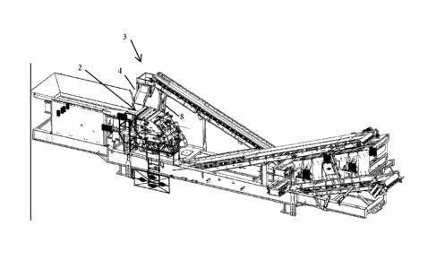
[0021] FIG. 5 is a full plant perspective view of the present invention
which in a
configuration as shown in FIGs. 1 and 4.
DETAILED DESCRIPTION OF THE DRAWINGS
[0022] Now referring to the drawings where like numerals refer to like
matter
throughout, and more specifically to FIG. 1, there is shown a dual
positionable chute 4 in
the closed-circuit chute position. Material is sorted by a screen with
portions of the material
directed onto the recirculating conveyor 1. Recirculating conveyor 1 then
discharges into
the head section 3 and then to the dual positionable chute 4 and into the
feeder hopper 2 for
re-crushing. The head section 3 is attached directly to the recirculating
conveyor 1 and
Date Recue/Date Received 2021-11-17
Ref No. 11800.091CA
moves in accordance with the conveyor 1. This head section 3 does not have any
additional
wear items as material will primarily contact the chute 4. The chute 4 is in
an embodiment
preferably fully lined with replaceable abrasion resistant liners and is
connected to the head
section 3 by a hinged mechanism 5. While in closed circuit position, the dual
actuators 6 are
to be fully retracted or until the chute 4 rests against the bottom of the
head section 3.
[0023] Now referring to FIG. 2, there is shown the dual positionable
recirculating
chute 4 in the open circuit position. The open circuit position of the chute 4
can be utilized
in two ways. First, material is sorted by the screen and then directed onto
the recirculating
conveyor 1. The recirculating conveyor 1 then discharges into the head section
3 and drops
onto the chute 4 to be discharged off plant. Second, in a trashing situation,
the plant will
continue to run without new rock being added into the hopper. Once the rock
has been all
distributed and cycled through the plant and no rock is being directed up the
recirculating
conveyor 1, the open circuit position can be used to discharge unwanted
materials off the
side of the plant. The chute 4 is held in position by the hinge 5 and the dual
actuators 6 are
actuated to fully extend, or until chute 4 comes to rest against the hinge 5.
Supporting the
discharge end of the recirculating conveyor are conveyor supports 8.
[0024] The unwanted fabric material responds poorly to the change of
directions due
to its weight and size. Because of this, the head section 3 length has been
designed to stay
out of the material path. Due to the angled troughing rolls in the
recirculating conveyor 1,
the material conveyed on the belt will collect and ride down the center of the
belt forming a
bell curved shape distribution across the width of the belt. The flashing on
the belt 7 acts as
a boundary on either side of the recirculating conveyor 1 to keep the material
within its
bounds.
6
Date Recue/Date Received 2021-11-17
Ref No. 11800.091CA
[0025] Now referring to FIG. 3, the fixed side of the head section 3 is
outside of the
bounds of the recirculating conveyor flashing 7. Therefore, any material (rock
or unwanted)
will drop through the head section 3 and make contact with the chute 4
eliminating the
change of direction that would be necessary had this head section 3 been made
to pass into
the material path.
[0026] As the equipment needs to travel over the road from work site to
work site,
the machine must conform to travel envelope restrictions. Extremities of the
equipment are
folded within these envelope restrictions prior to transport. The geometry of
the chute hinge
allows for the chute to fold down along the side of the machine during
transport. This
same hinge 5 geometry is such that during operation, the chute can direct
material into the
feeder hopper 2.
[0027] Now referring to FIGs. 1- 5, the system material processing plant
of the
present invention can be reconfigured rapidly from a closed circuit to an open
circuit
configuration with the simple manipulation of a single hydraulic control valve
which could
move the actuators 6 to expand and contract and thereby cause the chute 4 to
hinge from a
right discharge to a left discharge direction and vice versa.
[0028] The figures show a pair of actuators which may be preferred but
any number
of a plurality of actuators will provide at least some of the benefits as
described herein. The
actuators may be pneumatic, electro-mechanical, crisscross, or other suitable
substitutes.
[0029] It is believed that when these teachings are combined with the
known prior
art by a person skilled in the art of mobile rock crushing and screening
operations and
equipment manufacture, many of the beneficial aspects and the precise
approaches to
achieve those benefits will become apparent.
7
Date Recue/Date Received 2021-11-17
Ref No. 11800.091CA
[0030] It will be understood that certain features and sub-combinations
are of utility
and may be employed without reference to other features and sub-combinations.
This is
contemplated by and is within the scope of the claims.
[0031] Since many possible embodiments may be made of the invention
without
departing from the scope thereof, it is understood that all matter herein set
forth or shown in
the accompanying drawings is to be interpreted as illustrative and not in a
limiting sense.
8
Date Recue/Date Received 2021-11-17