Note: Descriptions are shown in the official language in which they were submitted.
WO 2020/243666
PCT/US2020/035450
A BIOCOMPATIBLE MEMBRANE COMPOSITE
FIELD
[0001] The present invention relates generally to the
field of implantable
devices and, in particular, to a biocompatible membrane composite and uses
thereof.
BACKGROUND
[0002] Biological therapies are increasingly viable
methods for treating
peripheral artery disease, aneurysm, heart disease, Alzheimer's and
Parkinson's diseases, autism, blindness, diabetes, and other pathologies.
[0003] With respect to biological therapies in general,
cells, viruses, viral
vectors, bacteria, proteins, antibodies, and other bioactive moieties may be
introduced into a patient by surgical or interventional methods that place the
bioactive moiety into a tissue bed of a patient. Often the bioactive moieties
are
first placed in a device that is then inserted into a patient. Alternatively,
the
device may be inserted into a patient first with the bioactive moiety added
later.
[0004] The implantation of external devices (e.g., cell
encapsulation
devices, sensors, and/or monitors for measuring physical parameters and/or
analytes in the body) triggers an immune response in which foreign body giant
cells form and at least partially encapsulate the implanted device. The device
may be formed of one or more biocompatible membranes or other
biocompatible materials that permit the passage of nutrients or other
therapeutically useful substances through but prevent the passage of the cells
therethrough. The presence of foreign body giant cells at or near the cell
impermeable interface makes it difficult, if not impossible for blood vessels
to
form in close proximity to this surface, thereby restricting access to the
oxygen,
nutrients, analytes or other signaling across the device interface needed for
adequate device function.
[0005] Thus, there remains a need in the art for a
material that can be
utilized in or that can provide an environment that is able to mitigate or
tailor
1
CA 03139585 2021- 11-25
WO 2020/243666
PCT/US2020/035450
the foreign body response such that sufficient vascularization occurs at or
near
the surface of a cell impermeable interface, thereby permitting the implanted,
encapsulated cells to survive and secrete a therapeutically useful substance
and that permits the implanted device access to analytes and physical
parameters for measurement.
SUMMARY
[0006] In one Aspect, ("Aspect 1"), a biocompatible
membrane composite
includes a first layer having first solid features with a first solid feature
spacing,
where a majority of the first solid feature spacing is less than about 50
microns,
and a second layer having second solid features with a second solid feature
spacing, where a majority of the second solid feature spacing is greater than
about 50 microns.
[0007] According to another Aspect, ("Aspect 2") further
to Aspect 1, the
first layer includes a majority of a representative minor axis from about 3
microns to about 20 microns.
[0008] According to another Aspect, ("Aspect 3") further
to Aspect 1 or
Aspect 2, the second layer has a first pore size greater than about 9 microns
in
effective diameter.
[0009] According to another Aspect, ("Aspect 4") further
to any one of
Aspects 1 to 3, the first layer has a first thickness less than about 200
microns.
[0010] According to another Aspect, ("Aspect 5") further
to any one of
Aspects 1 to 4, the first layer has a second pore size from about 1 micron to
about 9 microns in effective diameter.
[0011] According to another Aspect, ("Aspect 6") further
to Aspect 5, the
solid features of at least one of the first layer and the second layer are
connected by fibrils and the fibrils are deformable.
[0012] According to another Aspect, ("Aspect 7") further
to any one of
Aspects 1 to 5, the second layer has a second thickness from about 30
microns to about 200 microns.
2
CA 03139585 2021- 11-25
WO 2020/243666
PCT/US2020/035450
[0013] According to another Aspect, ("Aspect 8") any one
of Aspects 1 to
6, at least one of the first layer and the second layer includes a polymer
selected from an expanded polytetrafluoroethylene (ePTFE) membrane, a
fluorinated ethylene propylene (FEP) membrane and a modified ePTFE
membrane.
[0014] According to another Aspect, ("Aspect 9") further
to any one of
Aspects 1 to 8, the biocompatible membrane composite has thereon a surface
coating that includes one or more members selected from antimicrobial agents,
antibodies, pharmaceuticals, and biologically active molecules.
[0015] According to another Aspect, ("Aspect 10") further
to any one of
Aspects 1 to 9, at least one of the first layer and the second layer is an
expanded polytetrafluoroethylene membrane.
[0016] According to another Aspect, ("Aspect 11") further
to any one of
Aspects 1 to 10, the second layer is a spunbound non-woven polyester
material.
[0017] According to another Aspect, ("Aspect 12") further
to any one of
Aspects 1-10, including a reinforcing layer.
[0018] According to another Aspect, ("Aspect 13") further
to Aspect 12,
the reinforcing layer is a woven or non-woven textile.
[0019] According to another Aspect, ("Aspect 14") further
to any one of
Aspects 1 to 13, the solid features of the first layer includes a
representative
minor axis, a representative major axis, and a solid feature depth, and where
a
majority of at least two of the representative minor axis, the representative
major axis, and the solid feature depth are greater than about 5 microns.
[0020] In another Aspect, ("Aspect 15"), further to any
one of Aspects 1
to 14, including a first layer having a first pore size from about 1 micron to
about 9 microns in effective diameter, a first thickness less than about 200
microns, and first solid features having a majority of a first solid feature
spacing
less than about 50 microns, where a majority of the first solid features have
a
first representative minor axis from about 3 microns to about 20 microns and a
second layer.
3
CA 03139585 2021- 11-25
WO 2020/243666
PCT/US2020/035450
[0021] According to another Aspect, ("Aspect 16") further
to any one of
Aspects 1 to 15, the second layer has a pore size greater than about 9 microns
in effective diameter.
[0022] According to another Aspect, ("Aspect 17") further
to any one of
Aspects 1 to 16, the second layer includes second solid features with a
majority of a second solid feature spacing greater than about 50 microns.
[0023] According to another Aspect, ("Aspect 18") further
to any one of
Aspects 15 to 17, the second layer has a second thickness from about 30
microns to about 200 microns.
[0024] According to another Aspect, ("Aspect 19") further
to any one of
Aspects 15 to 18, the first solid features of the first layer each include a
majority of a first representative major axis and a first solid feature depth,
where a majority of at least two of the first representative minor axis, the
first
representative major axis, and the first solid feature depth are greater than
about 5 microns.
[0025] According to another Aspect, ("Aspect 20") further
to any one of
Aspects 15 to 19, the solid features are connected by fibrils and the fibrils
are
deform able.
[0026] According to another Aspect, ("Aspect 21") further
to any one of
Aspects 15 to 20, the second layer includes second solid features and a
majority of the second solid features has a second representative minor axis
that is less than about 40 microns.
[0027] According to another Aspect, ("Aspect 22") further
to any one of
Aspects 15 to 21, the second layer includes a second representative major axis
and a second solid feature depth, and wherein a majority of at least two of
the
second representative minor axis, the second representative major axis, and
the second solid feature depth is greater than about 5 microns.
[0028] According to another Aspect, ("Aspect 23") further
to any one of
Aspects 15 to 22, where at least one of the first layer and the second layer
is a
polymer selected from an expanded polytetrafluoroethylene (ePTFE)
4
CA 03139585 2021- 11-25
WO 2020/243666
PCT/US2020/035450
membrane, a fluorinated ethylene propylene (FEP) membrane and a modified
ePTFE membrane.
[0029] According to another Aspect, ("Aspect 24") further
to any one of
Aspects 15 to 23, the second layer is a spunbound non-woven polyester
material.
[0030] According to another Aspect, ("Aspect 25") further
to any one of
Aspects 15 to 24, at least one of the first layer and the second layer
includes a
polymer, fluoropolymer membranes, non-fluoropolymer membranes, a woven
biocorripatible textile, a non-woven biocompatible textile, woven or non-woven
collections of fibers or yarns, fibrous matrices, and combinations thereof.
[0031] According to another Aspect, ("Aspect 26") further
to any one of
Aspects 15 to 25, the first solid features of the first layer include a member
selected from a thermoplastic polymer, polyurethanes, silicones, rubbers,
epoxies and combinations thereof.
[0032] According to another Aspect, ("Aspect 27") further
to any one of
Aspects 15 to 26, including a reinforcing component.
[0033] According to another Aspect, ("Aspect 28") further
to Aspect 27,
the reinforcing component is a woven or non-woven textile.
[0034] According to another Aspect, ("Aspect 29") further
to any one of
Aspects 15 to 28, the biocornpatible membrane composite has thereon a
surface coating that includes one or more members selected from antimicrobial
agents, antibodies, pharmaceuticals, and biologically active molecules.
[0035] According to another Aspect, ("Aspect 30") further
to any one of
Aspects 15 to 29, the bioconwatible membrane composite has a hydrophilic
coating thereon.
[0036] According to another Aspect, ("Aspect 31") further
to any one of
Aspects 15 to 30, the first layer includes bondable solid features where the
bondable solid features are bonded to an implantable device or implantable
cell
system.
[0037] According to another Aspect, ("Aspect 32") further
to Aspect 31,
the implantable device is a scaffold.
CA 03139585 2021- 11-25
P038] According to another Aspect, ("Aspect 33") further to Aspect
32,
the scaffold is a cell culture matrix.
[0039] According to another Aspect, ("Aspect 34") further to Aspect
32,
the scaffold is an explant,
[0040] According to another Aspect, ("Aspect 35') further to Aspect
31,
the first solid features are at least partially bonded to a cell system.
[0041] According to another Aspect, ("Aspect 36") further to Aspect
35,
the cell system is a cell container.
10042] According to another Aspect, ("Aspect 37") further to Aspect
31,
the implantable device is a sensor.
[0043] According to another Aspect, ("Aspect 38") further to Aspect
31,
the cell system is a bioactive scaffold.
[0044] According to another Aspect ("Aspect 39") further to any of
the
preceding Aspects, a method for lowering blood glucose levels in a mammal
includes transplanting a cell encapsulated device including a biocompatible
membrane composite of any of the previous Aspects, where cells encapsulated
therein include a population of PDX1-positive pancreatic endoderm cells, and
where the pancreatic endoderm cells mature into insulin secreting cells,
thereby lowering blood glucose.
[0045] According to another Aspect ("Aspect 40") further to any of
the
preceding Aspects, the PDX1-positive pancreatic endoderm cells include a
mixture of cells further including endocrine and/or endocrine precursor cells,
where the endocrine and/or endocrine precursor cells express chromogranin A
(CHGA).
[0046] According to another Aspect ("Aspect 41") further to any of
the
preceding Aspects, a method for lowering blood glucose levels in a mammal
transplanting a cell encapsulation device as in Aspect 1, where cells
encapsulated therein include a population of PDX1-positive pancreatic
endoderm cells, and where the pancreatic endoderm cells mature into insulin
secreting cells, thereby lowering blood glucose.
6
Date Recue/Date Received 2023-05-11
WO 2020/243666
PCT/US2020/035450
[0047] According to another Aspect ("Aspect 42") further
to any of the
preceding Aspects, the PDXI -positive pancreatic endoderm cells include a
mixture of cells further including endocrine and/or endocrine precursor cells,
where the endocrine and/or endocrine precursor cells express chromogranin A
(CHGA).
[0048] According to another Aspect ("Aspect 43") further
to any of the
preceding Aspects, a method for lowering blood glucose levels in a mammal
includes transplanting a cell encapsulation device including at least one
sensor
and a biocompatible membrane composite that at least partially covers the
sensor where the biocompatible membrane composite includes a first layer
having first solid features with a majority of a first solid feature spacing
less
than about 50 microns and a second layer having second solid features with a
majority of a second solid feature spacing greater than about 50 microns,
where the first layer is positioned between the sensor and the second layer,
where at least a portion of the bonded features are intimately bonded to the
first layer, and a cell population including PDXI -positive pancreatic
endoderm
cells, and where the pancreatic endoderm cells mature into insulin secreting
cells, thereby lowering blood glucose.
[0049] According to another Aspect ("Aspect 44") further
to any of the
preceding Aspects, the PDXI -positive pancreatic endoderm cells include a
mixture of cells further including endocrine and/or endocrine precursor cells,
where the endocrine and/or endocrine precursor cells express chromogranin A
(CHGA).
[0050] According to another Aspect ("Aspect 45") further
to any of the
preceding Aspects, a method for lowering blood glucose levels in a mammal
includes transplanting at least one sensor and a biocompatible membrane
composite that at least partially covers the sensor where the biocompatible
membrane composite includes a first layer having first solid features with a
majority of a first solid feature spacing less than about 50 microns and a
second layer having second solid features with a majority of a second solid
feature spacing greater than about 50 microns, where the first layer is
7
CA 03139585 2021- 11-25
WO 2020/243666
PCT/US2020/035450
positioned between the sensor and the second layer, where at least a portion
of the bonded features are intimately bonded to the first layer, and a cell
population including PDX1-positive pancreatic endoderm cells, and where the
pancreatic endoderm cells mature into insulin secreting cells, thereby
lowering
blood glucose.
[0051] According to another Aspect ("Aspect 46") further
to any of the
preceding Aspects, the PDX1-positive pancreatic endoderm cells include a
mixture of cells further including endocrine and/or endocrine precursor cells,
where the endocrine and/or endocrine precursor cells express chromogranin A
(CHGA).
[0052] According to another Aspect ("Aspect 47") further
to any of the
preceding Aspects, an encapsulated in vitro PDX1-positive pancreatic
endoderm cells include a mixture of cell sub-populations including at least a
pancreatic progenitor population co-expressing PDX-1/NKX6.1.
[0053] According to another Aspect ("Aspect 48") further
to any of the
preceding Aspects, an encapsulated in vitro PDX1-positive pancreatic
endoderm cells includes a mixture of cell sub-populations including at least a
pancreatic progenitor population co-expressing PDX-1/NKX6.1 and a
pancreatic endocrine and/or endocrine precursor population expressing PDX-
1/NKX6.1 and CHGA.
[0054] According to another Aspect ("Aspect 49") further
to any of the
preceding Aspects, at least 30% of the population includes pancreatic
progenitor population co-expressing PDX-1/NKX6.1.
[0055] According to another Aspect ("Aspect 50") further
to any of the
preceding Aspects, at least 40% of the population includes pancreatic
progenitor population co-expressing PDX-1/NKX6.1.
[0056] According to another Aspect ("Aspect 51") further
to any of the
preceding Aspects, at least 50% of the population includes pancreatic
progenitor population co-expressing PDX-1/NKX6.1.
8
CA 03139585 2021- 11-25
[0057] According to another Aspect ("Aspect 52") further to any of
the
preceding Aspects, at least 20% of the population endocrine and/or endocrine
precursor population express PDX-1IN KX6.1/CHGA.
[0058] According to another Aspect ("Aspect 53") further to any of
the
preceding Aspects, at least 30% of the population endocrine and/or endocrine
precursor population express PDX-1/N KX6.1/CHGA.
[0059] According to another Aspect ("Aspect 54") further to any of
the
preceding Aspects, at least 40% of the population endocrine and/or endocrine
precursor population express PDX-1/N KX6.1/CHGA.
[0060] According to another Aspect ("Aspect 55") further to any of
the
preceding Aspects, the pancreatic progenitor cells and/or endocrine or
endocrine precursor cells are capable of maturing into insulin secreting cells
in
vivo.
[0061] According to another Aspect ("Aspect 56") further to any of
the
preceding Aspects, a method for producing insulin in vivo includes
transplanting a cell encapsulated device including a biocompatible membrane
composite of any of the previous Aspects and a population of PDX-1 pancreatic
endoderm cells mature into insulin secreting cells, where the insulin
secreting
cells secrete insulin in response to glucose stimulation.
[0062] According to another Aspect ("Aspect 57") further to any of
the
preceding Aspects, the PDX1-positive pancreatic endoderm cells include a
mixture of cells further including endocrine and/or endocrine precursor cells,
where the endocrine and/or endocrine precursor cells express chromogranin A
(CHGA).
[0063] According to another Aspect ("Aspect 58") further to any of
the
preceding Aspects, at least about 30% of the population are endocrine and/or
endocrine precursor population expressing PDX-1/NKX6.1/CHGA.
[0064] According to another Aspect ("Aspect 59") further to any of
the
preceding Aspects, an in vitro human PDX1-positive pancreatic endoderm cell
culture includes a mixture of PDX-1 positive pancreatic endoderm cells and at
least a transforming growth factor beta (TGF-beta) receptor kinase inhibitor.
9
Date Recue/Date Received 2023-05-11
WO 2020/243666
PCT/US2020/035450
[0065] According to another Aspect ("Aspect 60") further
to any of the
preceding Aspects, further including a bone rnorphogenetic protein (BMP)
inhibitor.
[0066] According to another Aspect ("Aspect 61") further
to any of the
preceding Aspects, the TGF-beta receptor kinase inhibitor is TGF-beta
receptor type 1 kinase inhibitor.
[0067] According to another Aspect ("Aspect 62") further
to any of the
preceding Aspects, the TGF-beta receptor kinase inhibitor is ALK5i.
[0068] According to another Aspect ("Aspect 63") further
to any of the
preceding Aspects, the BMP inhibitor is noggin.
BRIEF DESCRIPTION OF THE DRAWINGS
[0069] The accompanying drawings are included to provide a
further
understanding of the disclosure and are incorporated in and constitute a part
of
this specification, illustrate embodiments, and together with the description
serve to explain the principles of the disclosure.
[0070] FIG. 1A is a schematic illustration depicting the
determination of
solid feature spacing where three neighboring solid features represent the
corners of a triangle whose circumcircle has an interior devoid of additional
solid features and the solid feature spacing is the straight distance between
Iwo of the solid features forming the triangle in accordance with embodiments
described herein;
[0071] FIG. I B is a schematic illustration depicting the
determination of
non-neighboring solid features where the solid features form the corners of a
triangle whose circumcircle contains at least one additional solid feature in
accordance with embodiments described herein;
[0072] FIG. 2 is a scanning electron micrograph of the
spacing (white
lines) between solid features (white shapes) in an ePTFE membrane in
accordance with embodiments described herein;
CA 03139585 2021- 11-25
WO 2020/243666
PCT/US2020/035450
[0073] FIG. 3A is a schematic illustration depicting the
method to
determine the major axis and the minor axis of a solid feature in accordance
with embodiments described herein;
[0074] FIG. 3B is a schematic illustration depicting the
depth of a solid
feature in accordance with embodiments described herein;
[0075] FIG. 4 is a schematic illustration of the effective
diameter of a pore
in accordance with embodiments described herein;
[0076] FIG. 5 is a scanning electron micrograph (SEM)
showing a pore
size according to embodiments described herein;
[0077] FIG. 6A is a schematic illustration of a cross-
sectional view of an
implantable device that may be at least partially be covered by a
biocompatible
membrane composite in accordance with embodiments herein;
[0078] FIG. 6B is a schematic illustration of a bioactive
scaffold that may
be at least partially covered by a biocompatible membrane composite in
accordance with embodiments described herein;
[0079] FIG. 7 is a schematic illustration of a
biocompatible membrane
composite in accordance with embodiments described herein;
[0080] FIG 8 is a schematic illustration of another
biocompatible
membrane composite in accordance with embodiments described herein;
[0081] FIG 9 is a schematic illustration of yet another
biocompatible
membrane composite in accordance with embodiments described herein;
[0082] FIG. 10 is a scanning electron micrograph (SEM) of
the top
surface of the ePTFE mitigation layer of Example 1 in accordance with
embodiments described herein;
[0083] FIG. 11 is a scanning electron micrograph (SEM) of
the top
surface of a vascularization layer formed of a non-woven polyester utilized in
Example 1 in accordance with embodiments described herein; and
[0084] FIG. 12 is an exploded view of the configuration of
materials and
fixtures utilized in Example 1 in accordance with embodiments described
herein;
11
CA 03139585 2021- 11-25
WO 2020/243666
PCT/US2020/035450
[0085] FIG. 13 is a representative SEM image of the second
ePTFE layer
of Constructs A, B, and C of Example 2 having thereon FEP in accordance with
embodiments described herein;
[0086] FIG. 14 is a representative SEM image of the node
and fibril
structure of the second ePTFE membrane in Construct A of Example 2 in
accordance with embodiments described herein;
[0087] FIG. 15 is a representative SEM image of the node
and fibril
structure of the second ePTFE membrane in Construct B of Example 2 in
accordance with embodiments described herein;
[0088] FIG. 16 is a representative SEM image of the node
and fibril
structure of the second ePTFE membrane in Construct C of Example 2 in
accordance with embodiments described herein;
[0089] FIG. 17 is an SEM image of the cross-section of the
biocompatible
membrane composite of Construct A of Example 2 in accordance with
embodiments described herein;
[0090] FIG. 18 is an SEM image of the cross-section of the
biocompatible
membrane composite of Construct B of Example 2 in accordance with
embodiments described herein; and
[0091] FIG. 19 is an SEM image of the cross-section of the
biocompatible
membrane composite of Construct C of Example 2 in accordance with
embodiments described herein.
DETAILED DESCRIPTION
[0092] Persons skilled in the art will readily appreciate
that various
aspects of the present disclosure can be realized by any number of methods
and apparatus configured to perform the intended functions. It should also be
noted that the accompanying figures referred to herein are not necessarily
drawn to scale, and may be exaggerated to illustrate various aspects of the
present disclosure, and in that regard, the figures should not be construed as
limiting. Directional references such as "up," "down," "top," "left," "right,"
"front,"
and "back," among others are intended to refer to the orientation as
illustrated
12
CA 03139585 2021- 11-25
and described in the figure (or figures) to which the components and
directions
are referencing. It is to be appreciated that the terms "biocompatible
membrane composite" and "membrane composite" are used interchangeably
herein. It is to be noted that all ranges described herein are exemplary in
nature and include any and all values in between.
[0093] The present disclosure is directed to a biocompatible
membrane
composite that can provide an environment that is able to mitigate or tailor
the
foreign body response. The biocompatible membrane composite contains a
first layer and a second layer. Each layer is distinct, serving a unique
function
that aids in mitigating the formation of foreign body giant cells on a cell
impermeable layer of an implantable device or bioactive entity (e.g.,
bioactive
scaffold) In certain embodiments, the first layer functions as a mitigation
layer
and the second layer that functions as a vascularization layer. Herein, the
term
"first layer is used interchangeably with "mitigation layer and the term
"second
layer" is used interchangeably with "vascularization layer for ease of
convenience. The mitigation layer is positioned between the implantable
device or bioactive entity and the vascularization layer. In at least one
embodiment, the mitigation layer includes solid features (e.g., nodes) that
are
inherently present in the membrane forming the mitigation layer. A reinforcing
component may optionally be positioned on either side of the biocompatible
membrane composite (i.e., external to) or within the biocompatible membrane
composite (Le., internal to) to provide support to and prevent distortion of
the
biocompatible membrane corn posite. The mitigation layer may be to be
bonded (e.g., point bonded or welded) to the implantable device and/or
bioactive entity. In some embodiments, the mitigation layer and the
vascularization layer may be intimately bonded or otherwise connected to each
other to form a composite layer having an open/open structure. As used
herein, the terms "intimate bond" and "intimately bonded" refer to layers of
the
biocompatible membrane composite or to solid features within the
biocompatible membrane composite that are not readily separable or
13
Date Recue/Date Received 2023-05-11
WO 2020/243666
PCT/US2020/035450
detachable at any point on their suiface. It is to be appreciated that the
term
"about" as used herein denotes +/- 10% of the designated unit of measure.
[0094] In at least one embodiment, the mitigation layer
and the
vascularization layer are bonded together by one or more biocompatible
adhesive to form the biocompatible membrane composite. The adhesive may
be applied to the surface of one or both of the mitigation layer and the
vascularization layer in a manner to create a discrete or intimate bond
between
the layers. As used herein, the phrases "discrete bond" or "discretely bonded'
are meant to include bonding in intentional patterns of points and/or lines
around a continuous perimeter of a defined region. Non-limiting examples of
suitable biocompatible adhesives include fluorinated ethylene propylene (EEP),
a polycarbonate urethane, a thermoplastic fluoropolymer comprised of TEE
and PAVE, EFEP (ethylene fluorinated ethylene propylene), PEBAX (a
polyether amide), PVDF (poly vinylidene fluoride), CarbOSil (absilicone
polycarbonate urethane), Elasthane TM (a polyether urethane), PurSiP (a
silicone polyether urethane), polyethylene, high density polyethylene (HDPE),
ethylene chlorotetrafluoroethylene (ECTFE), perfluoroalkoxy (PEA),
polypropylene, polyethylene terephthalate (PET), and combinations thereof.
[0095] In some embodiments, the biocompatible membrane
composites
described herein may be utilized as a bio-interface for implantable sensors
that
are used to detect molecules produced in the body (such as glucose or other
biologically active molecules) or molecules that are produced outside the body
(such as molecules from ingested food). In another embodiment, the
biocompatible membrane composites may be used as a biocompatible cover
for implantable devices that provide or require molecules, signals, or
activity
within the body to elicit their function, such as, for example, pacemakers.
The
implantable device may be used to measure physical parameters of a body,
such as, for example, blood pressure. Herein, the temn "implantable device" is
used to encompass any implantable sensor or implantable device. In other
embodiments, the biocompatible membrane composites may be used as a
surface layer or as an encompassing cover for implantable devices that require
14
CA 03139585 2021- 11-25
WO 2020/243666
PCT/US2020/035450
vascularization for function but need protection from the host's immune
response, such as, but not limited to, the formation of foreign body giant
cells.
The implantable device may contain thereon a third layer (i.e., cell
impermeable layer). The cell impermeable layer serves as a microporous,
immune isolation barrier, is impervious to vascular ingrowth, and prevents
cellular contact from a host. In another embodiment, the biocompatible
membrane composites may be used in conjunction with tissues, cell scaffolds,
or cell encapsulation devices. Some examples include, but are not limited to,
explants, two-dimensional (2D) and three-dimensional (3D) cell culture
systems or cell containers. The collective term "cell system" is utilized
herein
to describe any biological entity that may be used in conjunction with the
biocompatible membrane composite.
[0096] Elements of implantable devices that could benefit
from the
function of the biocompatible membrane composites include, but are not limited
to, switches, sensors, bolometers, biosensors, chemical sensors, inertial
sensors, acoustic sensors, microphones, microspeakers, pressure sensors,
resonators, ultrasonic resonators, temperature sensors, vibration sensors,
microengines, actuators, thermal actuators, bimorph and unimorph actuators
(e.g., piezo and thermo), electrical rotating micromachines, microgears,
micropunnps, microtransmiitors, microengines, optical in icro-electro-
mechanical
systems (MEMS), micronnirrors, optical switches, and bio-micro-eledro-
mechanical systems (MEMS).
[0097] The interface of the biocompatible membrane
composite with the
implantable device is the mitigation layer, which is sufficiently porous to
permit
growth of vascular tissue into the mitigation layer. Thus, in some instances,
the mitigation layer acts as an initial vascularization layer. The mitigation
layer
creates a suitable environment to minimize or even prevent the formation of
contiguous layer of foreign body giant cells on or near a surface of the
implantable device, while allowing blood vessels to access the surface of the
implantable device_ Herein, layers that have openings large enough to allow
vascular ingrowth may be referred to as "open" layers. Blood vessels, which
CA 03139585 2021- 11-25
WO 2020/243666
PCT/US2020/035450
are the source of analytes and nutrients for the implantable device, need to
form at a distance from the implantable device so that the signals are easily
detected and transmitted. Non-limiting examples of the signal include glucose,
oxygen, a growth factor, or any analyte that is in need of sensing or
monitoring.
[0098] The mitigation layer is characterized at least in
part by the
inclusion of a plurality of solid features that have a solid feature spacing.
"Solid
features" as used herein may be defined as three dimensional components
within the mitigation layer that are generally immovable and resistant to
deformation when exposed to environmental forces such as, but not limited to,
cell movement (e.g., cellular migration and ingrowth, host
vascularization/endothelial blood vessel formation). The solid features in the
mitigation layer may be formed of thermoplastic polymers, polyurethanes,
silicones, rubbers, epoxies, and combinations thereof.
[0099] In embodiments where the mitigation layer has a
node and fibril
microstructure (e.g. formed from a fibrillated polymer), the nodes are the
solid
features and the fibrils are not solid features. Indeed, in some embodiments,
the fibrils may be removed, leaving only the nodes in the mitigation layer. In
embodiments where the nodes within the mitigation layer are the solid
features,
those nodes which are intimately bonded to the device or sensor interface and
are herein referred to as 'bonded solid features". "Non-bonded solid features"
are those solid features within the mitigation layer that are not bonded
(intimately bonded or otherwise) to the device or sensor interface. In one
embodiment, the mitigation layer is formed of an expanded
polytetrafluoroethylene (ePTFE) membrane having a node and fibril
microstructure.
[0100] The majority of the solid feature spacing of the
solid features
adjacent to the implantable device or cell system is less than about 50
microns,
less than about 40 microns, less than about 30 microns, less than about 20
microns, or less than about 10 microns. As used herein, the term "majority" is
meant to describe an amount over half (i.e., greater than 50%) of the measured
values for the parameter being measured. In some embodiments, the majority
16
CA 03139585 2021- 11-25
WO 2020/243666
PCT/US2020/035450
of the solid feature spacing may range from about 5 microns to about 45
microns, from about 10 microns to about 40 microns, from about 10 microns to
about 35 microns, or from about 15 microns to about 35 microns. The phrase
"solid feature spacing" is defined herein as the straight-line distance
between
two neighboring solid features. In this disclosure, solid features are
considered
neighboring if their centroids represent the corners of a triangle whose
circumcircle has an empty interior. As shown pictorially in FIG. 1A, the
designated solid feature (P) is connected to neighboring solid features (N) to
form a triangle 100 where the circumcircle 110 contains no solid features
within. Solid features (X) designate the solid features that are not
neighboring
solid features. Thus, in the instance depicted in FIG. 1A, the solid feature
spacing 130 is the straight distance between the designated solid features
(P),
(N). In contrast, the circumcircle 150 shown in FIG. 113 drawn from the
triangle
160 contains therein a solid feature (N), and as such, cannot be utilized to
determine the solid feature spacing in the mitigation layer (or the
vascularization layer). FIG. 2 is a scanning electron micrograph depicting
measured distances, e.g., the white lines 200 between the solid features 210
(white shapes) in a mitigation layer formed of an expanded
polytetrafluoroethylene membrane.
[0101] The solid features also include a representative
minor axis, a
representative major axis, and a solid feature depth. The representative minor
axis of a solid feature is defined herein as the length of the minor axis of
an
ellipse fit to the solid feature where the ellipse has the same area,
orientation,
and centroid as the solid feature. The representative major axis of a solid
feature is defined herein as the length of the major axis of an ellipse fit to
the
solid feature where the ellipse has the same area, orientation, and centroicl
as
the solid feature. The major axis is greater than or equal to the minor axis
in
length. The minor and major axes of an ellipse 320 to fit the solid feature
310
is shown pictorially in FIG. 3A. The representative minor axis of the solid
feature 310 is depicted by arrow 300, and the representative major axis of the
solid feature 310 is depicted by arrow 330. A majority of the solid features
has
17
CA 03139585 2021- 11-25
WO 2020/243666
PCT/US2020/035450
a minor axis that ranges in size from about 3 microns to about 20 microns,
from
about 3 microns to about 15 microns, or from about 3 microns to about 10
microns. The solid feature depth is the length of the projection of the solid
feature in the axis perpendicular to the surface of the layer (e.g.,
mitigation
layer or vascularization layer). The solid feature depth of the solid feature
310
is shown pictorially in FIG 3B. The depth of the solid feature 310 is depicted
by
line 340. In at least one embodiment, the depth of the solid features is equal
to
or less than the thickness of the mitigation layer. In at least one
embodiment, a
majority of at least two of the representative minor axis, representative
major
axis, and solid feature depth is greater than 5 microns.
[0102] In embodiments where the solid features are
interconnected by
fibrils or fibers, the boundary connecting the solid features creates a pore.
It is
necessary that these pores are open enough to allow rapid cellular ingrowth
and vascularization and not create a resistance to mass transport of oxygen
and nutrients. The pore effective diameter is measured by quantitative image
analysis (QIA) and performed on a scanning electron micrograph (SEM) image.
The term "effective diameter" of a pore is defined as the diameter of a circle
that has an area equal to the measured area of the surface pore. This
relationship is defined by the following equation:
Area
Effective Diameter = 2 x ¨.
r
[0103] Turning to FIG. 4, the effective diameter is the
diameter of the
circle 400 and the surface pore is designated by reference numeral 420. The
total pore area of a surface is the sum of the area of all pores at that
surface.
The pore size of a layer is the effective diameter of the pore that defines
the
point where roughly half the total pore area consists of pores with diameters
smaller than the pore size and half the total pore area consists of pores with
diameters greater than or equal to the pore size. FIG. 5 illustrates a pore
size
500 (white in color), pores smaller in size 510 (shown in light grey), and
pores
larger in size 520 (shown in dark grey). Pores that intersect with the edge of
the image 530 were excluded from analysis and are shown in black.
18
CA 03139585 2021- 11-25
WO 2020/243666
PCT/US2020/035450
[0104] The pore size of the mitigation layer may range
from about 1
micron to about 9 microns in effective diameter, from about 3 microns in
effective diameter to about 9 microns in effective diameter, or from about 4
micron in effective diameter to about 9 microns in effective diameter as
measured by quantitative image analysis (QIA) performed on a scanning
electron micrograph (SEM) image. The mitigation layer has a thickness that is
less than about 200 microns, less than about 290 microns, less than about 280
microns, less than about 270 microns, less than about 260 microns, less than
about 200 microns, less than about 190 microns, less than about 180 microns,
less than about 170 microns, less than about 160 microns, less than about 150
microns, less than about 140 microns, less than about 130 microns, less than
about 120 microns, less than about 110 microns, less than about 100 microns,
less than about 90 microns, less than about 80 microns, less than about 70
microns, or less than about 60 microns, less than 50 about microns, less than
about 40 microns, less than about 30 microns, less than about 20 microns, or
less than about 10 microns. The thickness of the mitigation layer may range
from about 60 microns to about 200 microns, from about 60 microns to about
170 microns, from about 60 to about 150 microns, from about 60 microns to
about 125 microns, from about 60 microns to about 100 microns, from about 3
microns to about 60 microns, from about 10 microns to about 50 microns, from
about 10 microns to about 40 microns, or from about 15 microns to about 35
microns. In some embodiments, the mitigation layer has a porosity greater
than about 60%. In other embodiments, the mitigation layer has a porosity
greater than about 70%, greater than about 80%, greater than about 90%, or
greater than about 95%. In some embodiments, the porosity may be about
98% or about 99%. The porosity of the mitigation layer may range from about
60% to about 98%, from about 70% to about 98%, or from about 80% to about
98%.
[0105] The anchoring of the implantable device and
ingrowth of vascular
tissue through the biocompatible membrane composite up to the surface of the
device is further facilitated by the second layer (i.e., vascularization
layer). The
19
CA 03139585 2021- 11-25
WO 2020/243666
PCT/US2020/035450
vascularization layer is an "open" layer that permits additional vascular
penetration from the host and also permits rapid anchoring and attachment of
the bioconnpatible membrane composite within the tissue of the host.
Additionally, the vascularization layer provides a porous matrix to harbor the
growth of a sufficient quantity of additional, new blood vessels, such as to
the
implantable device or the cell system. In embodiments where the
vascularization layer does not meet the same criteria of the mitigation layer
the
mitigation layer and vascularization layer are considered as separate and
distinct layers. The vascularization layer is designed such that there are
solid
features to enable host integration and attachment. These solid features have
increased spacing and pore sizes therebetween compared to the solid features
of the mitigation layer to facilitate a more rapid ingrowth of tissue into the
layer.
[0106]
In some embodiments, the majority of the solid feature spacing of
the solid features in the vascularization layer is greater than about 50
microns,
greater than about 60 microns, greater than about 70 microns, or greater than
about 80 microns. A majority of the solid features in the vascularization
layer
has a solid feature spacing that range from about 50 microns to about 90
microns, from about 60 microns to about 90 microns, or from about 70 microns
to about 90 microns. The pore size and overall thickness of the
vascularization
layer is sufficient to provide space to harbor the necessary quantities of
additional blood vessels to provide nutrients and oxygen to cells. A pore size
of the vascularization layer may be greater than about 9 microns in effective
diameter, greater than about 25 microns in effective diameter, greater than
about 50 microns in effective diameter, greater than about 75 microns in
effective diameter, greater than about 100 microns in effective diameter,
greater than about 125 microns in effective diameter, greater than about 150
microns in effective diameter, greater than about 175 microns in effective
diameter, or greater than about 200 microns in effective diameter as measured
by Q IA performed on an SEM image. In some embodiments, the pore size of
the vascularization layer may range from about 9 microns in effective diameter
to about 200 microns in effective diameter, from about 9 microns in effective
CA 03139585 2021- 11-25
WO 2020/243666
PCT/US2020/035450
diameter to about 50 microns in effective diameter, from about 15 microns in
effective diameter to about 50 microns in effective diameter from about 25
microns in effective diameter to about 50 microns in effective diameter, from
about 50 microns in effective diameter to about 200 microns in effective
diameter, from about 75 microns in effective diameter to about 175 microns in
effective diameter as measured by QIA performed on an SEM image.
[0107] Additionally, the vascularization layer may have a
thickness that is
greater than about 30 microns, greater than about 50 microns, greater than
about 75 microns, greater than about 100 microns, greater than about 125
microns, greater than about 150 microns, or greater than about 200 microns.
In addition, the thickness of the vascularization layer may range fronn about
30
microns to about 300 microns, from about 30 microns to about 200 microns,
from about 30 microns to about 100 microns, from about 100 microns to about
200 microns, or from about 100 microns to about 150 microns. In addition, a
majority of the solid features in the vascularization layer has a
representative
minor axis that is less than about 40 microns, less than about 30 microns,
less
than about 20 microns, less than about 10 microns, less than about 5 microns,
or less than about 3 microns. In some embodiments, the representative minor
axis may range in size from about 3 microns to about 40 microns, from about 3
microns to about 30 microns, from about 3 microns to about 20 microns, from
about 3 microns to about 10 microns, or from about 20 microns to about 40
microns. The solid features in the vascularization layer also have a major
axis
that greater in length than the minor axis and may effectively be unlimited in
length, such as a continuous fiber of a non-woven. The solid features in the
vascularization layer have a depth that is less than or equal to the total
thickness of the vascularization layer.
[0108] An optional reinforcing component may be included
to provide
mechanical support to the biocompatible membrane composite to minimize
distortion in viva This additional optional reinforcing component provides a
stiffness to the biocompatible membrane composite that is greater than the
biocompatible membrane composite itself. This optional reinforcing component
21
CA 03139585 2021- 11-25
WO 2020/243666
PCT/US2020/035450
could be continuous in nature or it may be present in discrete regions on the
biocompatible membrane composite, e.g., patterned across the entire surface
of the biocompatible membrane composite or located in specific locations such
as around the perimeter of the biocompatible membrane composite. Non-
limiting patterns suitable for the surface of the membrane composite include
dots, straight lines, angled lines, curved lines, dotted lines, grids, etc.
Patterns
forming the reinforcing component may be used singly or in combination. In
addition, the reinforcing component may be temporary in nature (e.g., formed
of a bioabsorbable material) or may be permanent in nature (e.g., a
polyethylene terephthalate (PET) mesh or Nitinol). A final determination of
the
component stiffness depends not only on the stiffness of a single reinforcing
component, but also on the location and restraint of the reinforcing component
in the final device form.
[0109] In at least one embodiment, the reinforcing
component may be
provided on the outer surface of the vascularization layer to strengthen the
biocompatible membrane composite against environmental forces. In this
orientation, the reinforcing component has a pore size sufficient to permit
vascular ingrowth, and is therefore is considered an "open" layer. Materials
useful as the reinforcing component include materials that are significantly
stiffer than the biocompatible membrane composite. Such materials include,
but are not limited to, open mesh biomaterial textiles, woven textiles, non-
woven textiles (e.g., collections of fibers or yarns), and fibrous matrices,
either
alone or in combination.
[0110] In some embodiments, the mitigation layer and
vascularization
layer may be bonded together by one or more biocompatible adhesive to form
the biocompatible membrane composite. The adhesive may be applied to the
surface of one or both of the mitigation layer and vascularization layer in a
manner to create a discrete or intimate bond between the layers. Non-limiting
examples of suitable biocompatible adhesives include fluorinated ethylene
propylene (FEP), a polycarbonate urethane, a thermoplastic fluoropolymer
comprised of TEE and PAVE, EFEP (ethylene fluorinated ethylene propylene),
22
CA 03139585 2021- 11-25
WO 2020/243666
PCT/US2020/035450
PEBAX (a polyether amide), PVDF (poly vinylidene fluoride), CarbOSil
(absilicone polycarbonate urethane), Elasthanem" (a polyether urethane),
PurSil (a silicone polyether urethane), polyethylene, high density
polyethylene
(HDPE), ethylene chlorotetrafluoroethylene (ECTFE), perfluoroalkoxy (PFA),
polypropylene, polyethylene terephthalate (PET), and combinations thereof.
[0111] In some embodiments, at least one of the mitigation
layer and the
vascularization layer may be formed of a polymer membrane or woven or non-
woven collections of fibers or yarns, or fibrous matrices, either alone or in
combination. Non-limiting examples of polymers that may be used include, but
are not limited to, alginate; cellulose acetate; polyalkylene glycols such as
polyethylene glycol and polypropylene glycol; panvinyl polymers such as
polyvinyl alcohol; chitosan; polyacrylates such as
polyhydroxyethylmethacrylate; agarose; hydrolyzed polyacrylonitrile;
polyacrylonitrile copolymers; polyvinyl acrylates such as polyethylene-co-
acrylic acid, polyalkylenes such as polypropylene, polyethylene;
polyvinylidene
fluoride; fluorinated ethylene propylene (FEP); perfluoroalkoxy alkane (PFA);
polyester sulfone (PES); polyurethanes; polyesters; and copolymers and
combinations thereof. In some embodiments, the vascularization layer may be
a spunbound, non-woven polyester or an expanded polytetrafluoroethylene
(ePTFE) membrane.
[0112] In some embodiments at least one of the mitigation
layer, the
vascularization layer, or the reinforcing component is formed of a non-woven
fabric. There are numerous types of non-woven fabrics, each of which may
vary in tightness of the weave and the thickness of the sheet. The filament
cross-section may be trilobal. The non-woven fabric may be a bonded fabric, a
formed fabric, or an engineered fabric that is manufactured by processes other
than weaving or knitting. In some embodiments, the non-woven fabric is a
porous, textile-like material, usually in a flat sheet form, and composed
primarily or entirely of fibers, such as staple fibers assembled in a web,
sheet,
or batt. The structure of the non-woven fabric is based on the arrangement of,
for example, staple fibers that are typically randomly arranged. In addition,
23
CA 03139585 2021- 11-25
WO 2020/243666
PCT/US2020/035450
non-woven fabrics can be created by a variety of techniques known in the
textile industry. Various methods may create carded, wet laid, melt blown,
spunbonded, or air laid non-woven materials. Methods and substrates are
described, for example, in U.S. Patent Publication No. 2010/0151575 to Colter,
et al. In one embodiment, the non-woven fabric is polytetrafluoroethylene
(PIPE). In another embodiment, the non-woven fabric is a spunbound
polyester. The density of the non-woven fabric may be varied depending upon
the processing conditions. In one embodiment, the non-woven fabric is a
spunbound polyester with a basic weight from about 10 to about 20 g/rn2a
nominal thickness from about 75 to about 150 microns, and a fiber diameter
from about 20 to about 40 microns. The filament cross-section is trilobal. The
filament cross-section is trilobal. In some embodiments, the non-woven fabrics
are bioabsorbable.
[0113] In some embodiments, the polymer(s) forming the
polymer
membrane of the mitigation layer and/or vascularization layer is a
fibrillatable
polymer. Fibrillatable, as defined herein, refers to the ability to introduce
fibrils
to a polymer membrane including, but not limited to, converting portions of
the
solid features into fibrils_ For example, the fibrils are the solid elements
that
span the gaps between the solid features. Fibrils are generally not resistant
to
deformation upon exposure to environmental forces, and are therefore
deformable. The majority of deformable fibrils in the mitigation layer and/or
vascularization layer may have a diameter less than about 2 microns, less than
about 1 micron, less than about 0.75 microns, less than about 0.50 microns, or
less than about 0.25 microns. In some embodiments, the fibrils may have a
diameter from about 0.25 microns to about 2 microns, from about 0.5 microns
to about 2 microns, or from about 0.75 microns to about 2 microns.
[0114] In some embodiments, the solid features of one or
both of the
mitigation layer and the vascularization layer may be formed by
microlithography, micro-molding, machining, selectively depositing, or
printing
(or otherwise laying down) a polymer (e.g., thermoplastic) onto a mitigation
layer or a vascularization layer to form at least a part of a solid feature.
Any
24
CA 03139585 2021- 11-25
WO 2020/243666
PCT/US2020/035450
conventional printing technique such as transfer coating, screen printing,
gravure printing, ink-jet printing, patterned imbibing, and knife coating may
be
utilized to place the thermoplastic polymer onto the mitigation layer and/or
vascularization layer. Optionally, the pattern may be printed onto a liner and
applied to the mitigation layer, vascularization layer, or an implantable
device.
[0115] Materials used to form the solid features include,
but are not
limited to, thermoplastics, polyurethane, polypropylene, silicones, rubbers,
epoxies, polyethylene, polyether amide, polyetheretherketone,
polyphenylsulfone, polysulfone, silicone polycarbonate urethane, polyether
urethane, polycarbonate urethane, silicone polyether urethane, polyester,
polyester terephthalate, melt-processable fluoropolymers, such as, for
example, fluorinated ethylene propylene (FEP), tetrafluoroethylene-
(perfluoroalkyl) vinyl ether (PFA), an alternating copolymer of ethylene and
tetrafluoroethylene (ETFE), a terpolyrner of tetrafluoroethylene (TFE),
hexafluoropropylene (HFP) and vinylidene fluoride (THV), polyvinylidene
fluoride (PVDF), and combinations thereof. In some embodiments,
polytetrafluoroethylene may be used to form the pattern features. In further
embodiments, the solid features may be separately formed and adhered to the
surface of the vascularization layer or surface of the implantable device (not
illustrated).
[0116] Non-limiting examples of fibrillatable polymers
that may be used
to form one or more of the mitigation layer, and the vascularization layer,
and
optional cell impermeable layer include, but are not limited to,
tetrafluoroethylene (TFE) polymers such as polytetrafluoroethylene (PTFE),
expanded PTFE (ePTFE), modified PTFE, TFE copolymers, polyvinylidene
fluoride (PVDF), poly (p-xylylene) (ePPX) as taught in U.S. Patent Publication
No. 2016/0032069 to Sbriglia, porous ultra-high molecular weight polyethylene
(eUHMWPE) as taught in U.S. Patent No. 9,926,416 to Sbriglia, porous
ethylene tetrafluoroethylene (eETFE) as taught in U.S. Patent No. 9,932,429 to
Sbriglia, and porous vinylidene fluoride-co-tetrafluoroethylene or
CA 03139585 2021- 11-25
WO 2020/243666
PCT/US2020/035450
trifluoroethylene [VDF-co-(TFE or TrFE)] polymers as taught in U.S. Patent No.
9,441,088 to Sbriglia and combinations thereof.
[0117] In some embodiments, the fibrillatable polymer is a
fluoropolymer
membrane such as expanded polytetrafluoroethylene (ePTFE) membrane.
Expanded polytetrafluoroethylene (ePTFE) (and other fibrillated polymers) has
a node and fibril microstructure where the nodes are interconnected by the
fibrils and the pores are the space located between the nodes and fibrils
throughout the membrane. As used herein, the term "node" is meant to denote
a solid feature consisting of largely of polymer material. When defomnable
fibrils are present, these nodes reside at the junction of multiple fibrils.
In some
embodiments the fibrils may be removed from the membrane, such as, for
example, by plasma etching. In at least one embodiment, an expanded
polytetrafluoroethylene membrane is used in one or more of the mitigation
layer, the vascularization layer and the optional cell impermeable layer.
Expanded polytetrafluoroethylene membranes such as, but not limited to, those
prepared in accordance with the methods described in U.S. Patent No.
3,953,566 to Gore, U.S. Patent No. 7,306,729 to Bacino etal., U.S. Patent No.
5,476,589 to Bacino, WO 94/13469 to Bacino, U.S. Patent No. 5,814,405 to
Branca et al. or U.S. Patent No. 5,183,545 to Branca et at. may be used
herein.
[0118] In some embodiments, one or more of the mitigation
layer and the
vascularization layer may be formed of a fluoropolymer membrane, such as,
but not limited to, an expanded polytetrafluoroethylene (ePTFE) membrane, a
modified ePTFE membrane, a tetrafluoroethylene (TFE) copolymer membrane,
a polyvinylidene fluoride (PVDF) membrane, or a fluorinated ethylene
propylene (FEP) membrane. In further embodiments, the vascularization layer
may include biocompatible textiles, including wovens and non-wovens (e.g., a
spunbound non-woven, melt blown fibrous materials, electrospun nanofibers,
etc.), non-fluoropolymer membranes such as polyvinylidene difluoride (PVDF),
nanofibers, polysulfones, polyethersulfones, polyarlysulfones, polyether ether
ketone (PEEK), polyethylenes, polypropylenes, and polyimides. In some
26
CA 03139585 2021- 11-25
WO 2020/243666
PCT/US2020/035450
embodiments, the vascularization layer is a spunbound, non-woven polyester
or an expanded polytetrafluoroethylene (ePTFE) membrane.
[0119] In some embodiments, it may be desirable for one or
more of the
vascularization layer and reinforcing component to be non-permeant (e.g.,
biodegradable). In such instances, a biodegradable material may be used to
form the vascularization layer and/or the reinforcing component. Suitable
examples of biodegradable materials include, but are not limited to,
polyglycolide:trimethylene carbonate (PGA:TMC), polyalphahydroxy acid such
as polylactic acid, polyglycolic acid, poly (glycolide), and poly(lactide-co-
caprolactone), poly(caprolactone), poly(carbonates), poly(dioxanone), poly
(hydroxybutyrates), poly(hydroxyvalerates), poly (hydroxybutyrates-co-
valerates), expanded polyparaxylylene (ePLLA), such as is taught in U.S.
Patent Publication No. 2016/0032069 to Sbriglia, and copolymers and blends
thereof. Alternatively, the vascularization layer may be coated with a bio-
absorbable material or a bio-absorbable material may be incorporated into or
onto the vascularization layer in the form of a powder. Coated materials may
promote infection site reduction, vascularization, and favorable type 1
collagen
deposition.
[0120] The biocompatible membrane composite may have at
least
partially thereon a surface coating, such as a Zwitterion non-fouling coating,
a
hydrophilic coating, or a CBAS*/Heparin coating (commercially available from
W.L. Gore & Associates, Inc.). The surface coating may also or alternatively
contain antimicrobial agents, antibodies (e.g., anti-CD 47 antibodies (anti-
fibrotic)), pharmaceuticals, biologically active molecules (e.g., stimulators
of
vascularization such as FGF, VEGF, endoglin, PDGF, angiopoetins, and
integrins; Anti-fibrotic such as TGFb inhibitors, sirolimus, CSF1R inhibitors,
anti-inflammatory/immune modulators such as CXCL12, and corticosteroids),
and combinations thereof.
[0121] Turning to FIG. BA, in at least one embodiment, the
biocompatible
membrane composite may be used in combination with an implantable device
600. In particular, the biocompatible membrane composite (not shown) may
27
CA 03139585 2021- 11-25
WO 2020/243666
PCT/US2020/035450
partially or fully cover the enclosure 605. Enclosure 605 may be a pouch or
container for carrying corn ponents 610 of a sensor, pacemaker, or electrical
lead, or it may be the implantable device itself. In another embodiment
depicted in FIG. 613, the biocompatible membrane composite (not shown) may
partially or fully cover the exterior of the cell system 620 and/or a portion
or all
of the structural elements 650. Section 630 is magnified to show individual
structural elements 650 of the cell system and cells 640 growing with cell
system 620.
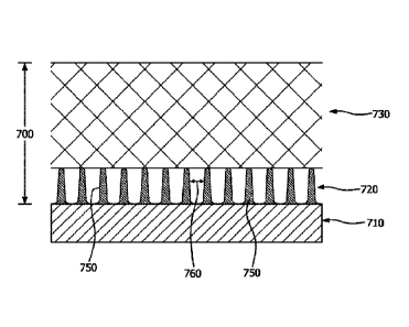
[0122] A biocompatible membrane composite 700 is depicted
in FIG. 7.
As illustrated in FIG. 7, the biocompatible membrane composite 700 includes a
mitigation layer (i.e., first layer) 720 and a vascularization layer (i.e.,
second
layer) 730. The biocompatible membrane composite 700 may be utilized to at
least partially cover, encompass, or surround an implantable device 710. In
the depicted embodiment, solid features 750 are attached to the surface of an
implantable device 710 to form the mitigation layer 720. "Attached" as used
herein is mean to include intimately attached or discretely attached. In some
embodiments, the solid features 750 do not penetrate into the vascularization
layer 730. The solid features 750 are depicted in FIG. 7 as being essentially
the same height and width and extending between the implantable device 710
and the vascularization layer 730, although it is to be appreciated this is an
example and the solid features 750 may vary in height and/or width. The
distance between solid features 750 is the solid feature spacing 760.
[0123] FIG. 8 is another biocompatible composite. As
illustrated in FIG.
8, the biocompatible membrane composite 800 includes a mitigation layer 820
and a vascularization layer 830. In the depicted embodiment, the solid
features 850 are nodes that differ in height and width, and may or may not
extend the distance between the implantable device 810 and the
vascularization layer 830. The solid features 850 are connected by fibrils
870.
In FIG. 8, the majority of the solid feature depth is less than the total
thickness
of the mitigation layer 820. Bondable solid features 880 may be attached to
the surface of the implantable device 810.
28
CA 03139585 2021- 11-25
WO 2020/243666
PCT/US2020/035450
[0124] Turning to FIG. 9, a biocompatible membrane
composite 900 is
shown. The biocompatible membrane composite 900 includes a mitigation
layer 920 and a vascularization layer 930. The biocompatible membrane
composite 900 may at least partially cover or encompass the implantable
device 910. In this embodiment, solid features within the mitigation layer 920
are nodes formed of an expanded polytetrafluoroethylene membrane. The
nodes 950 are interconnected by fibrils 970. Nodes 950, 980 are positioned
within the mitigation layer 920. Bondable solid features or nodes 980,
however, are not only within the mitigation layer 920, but also are in contact
with, and may be intimately bonded to, the implantable device 910.
[0125] It is to be appreciated that in each of the
embodiments described
in FIGS. 7-9, a cell system may replace the implantable device and such
embodiments are considered to be within the purview of the invention.
TEST METHODS
Porosity
[0126] The porosity of a layer is defined herein as the
proportion of layer
volume consisting of pore space compared to the total volume of the layer.
The porosity is calculated by comparing the bulk density of a porous construct
consisting of solid fraction and void fraction to the density of the solid
fraction
using the following equation:
DenstrY ______________________________ Bulk
Porosity = (1 ) x 100%.
DenSttnyliti Fraction
Mass/Area
[0127] Samples were cut (either by hand, laser, or die) to
a known
geometry. The dimensions of the sample were measured or verified and the
area was calculated in m2. The sample was then weighed in grams on a
calibrated scale. The mass in grams was divided by the area in m2 to calculate
the mass per area in g/m2.
29
CA 03139585 2021- 11-25
WO 2020/243666
PCT/US2020/035450
Thickness
[0128] The thickness of the layers in the bioconnpatible
membrane
composites were measured by quantitative image analysis (01A) of cross-
sectional SEM images. Cross-sectional SEM images were generated by fixing
membranes to an adhesive, cutting the film by hand using a liquid-nitrogen-
cooled razor blade, and then standing the adhesive backed film on end such
that the cross-section was vertical. The sample was then sputter coated using
an Emitech K550X sputter coater (commercially available from Quorum
Technologies Ltd, UK) and platinum target. The sample was then imaged
using a FEI Quanta 400 scanning electron microscope from Thermo Scientific.
[0129] Layers within the cross-section SEM images were
then measured
for thickness using ImageJ 1.51h from the National Institutes of Health (NIH).
The image scale was set per the scale provided by the SEM. The layer of
interest was isolated and cropped using the free-hand tool. A number of at
least ten equally spaced lines were then drawn in the direction of the layer
thickness. The lengths of all lines were measured and averaged to define the
layer thickness.
Stiffness
[0130] A stiffness test was performed based on ASTM D790-
17 Standard
test method for flexural properties of unreinforced and reinforced plastics
and
electrical insulating material. This method was used to determine the
stiffness
for biocompatible membrane composite layers and/or the final device.
[0131] Procedure B of the ASTM method was followed and
includes
greater than 5% strain and type 1 crosshead position for deflection. The
dimensions of the fixture were adjusted to have a span of 16 mm and a radius
of support and nosepiece of 1.6 mm. The test parameters used were a
deflection of 3.14 mm and a test speed of 96.8 mm/m in. In cases where the
sample width differed from the standard 1 cm, the force was normalized to a 1
cm sample width by the linear ratio.
[0132] The load was reported in N/cm at maximum
deflection.
CA 03139585 2021- 11-25
WO 2020/243666
PCT/US2020/035450
SEM Sample Preparation
[0133] SEM samples were prepared by first fixing the
membrane
composite or membrane composite layer(s) of an adhesive for handling, with
the side opposite the side intended for imaging facing the adhesive. The film
was then cut to provide an approximately 3 mm x 3 mm area for imaging. The
sample was then sputter coated using an Emitech k550X sputter coater and
platinum target. Images were then taken using a FEI Quanta 400 scanning
electron microscope from Thermo Scientific at a magnificent and resolution
that
allowed visualization of a sufficient number of features for robust analysis
while
ensuring each feature's minimum dimension was at least five pixels in length.
Solid Feature Spacing
[0134] Solid feature was determined by analyzing SEM
images in ImageJ
1.51h from the National Institute of Health (NIH). The image scale was set
based on the scale provided by the SEM image. Features were identified and
isolated through a combination of thresholding based on size/shading and/or
manual identification. In instances where the structure consists of a
continuous
structure, such as a nonwoven or etched surface, as opposed to a structure
with discrete solid features, solid features are defined as the portion of the
structure surrounding voids the their corresponding spacing extending from
one side of the void to the opposing side. After isolating the features, a
Delaunay Triangulation was performed to identify neighboring features.
Triangulations whose circurncircle extended beyond the edge of the image
were disregarded from the analysis. Lines were drawn between the nearest
edges of neighboring features and measured for length to define spacing
between neighboring features (see, e.g., FIG. 1A).
[0135] The median of all measured solid feature spacings
marks the
value that is less than or equal to half of the measured solid feature
spacings
and greater than or equal to half of the measured solid feature spacings.
Therefore, if the measured median is above or below some value, the majority
31
CA 03139585 2021- 11-25
WO 2020/243666
PCT/US2020/035450
of measurements is similarly above or below the value. As such, the median is
used as summary statistic to represent the majority of solid feature spacings.
Measurement of Representative Minor Axis and Representative Major Axis
[0136] The representative minor axis was measured by
analyzing SEM
images of membrane surfaces in ImageJ 1.51h from the NIH. The image scale
was set based on the scale provided by the SEM image. Features were
identified and isolated through a combination of thresholding based on
size/shading anchor manual identification. After isolating the features, the
built
in particle analysis capabilities were leveraged to determine the major and
minor axis of the representative ellipse. The minor axis of this ellipse is
the
representative minor axis of the measured feature. The major axis of this
ellipse is the representative major axis of the measured feature. The median
of
all measured minor axes marks the value that is less than or equal to half of
the measured minor axes and greater than or equal to half of the measured
minor axes. Similarly, the median of all measured major axes marks the value
that is less than or equal to half of the measured major axes and greater than
or equal to half of the measured major axes_ In both cases, if the measured
median is above or below some value, the majority of measurements is
similarly above or below the value. As such, the median is used as summary
statistic to represent the majority of solid feature representative minor axes
and
representative major axes.
Solid Feature Depth
[0137] Solid feature depth was determined by using
quantitative image
analysis (QIN of SEM images of membrane cross-sections. Cross-sectional
SEM images were generated by fixing films to an adhesive, cutting the film by
hand using a liquid-nitrogen-cooled razor blade, and then standing the
adhesive backed film on end such that the cross-section was vertical. The
sample was then sputter coated using an Emitech K550X sputter coater
(commercially available from Quorum Technologies Ltd, UK) and platinum
32
CA 03139585 2021- 11-25
WO 2020/243666
PCT/US2020/035450
target. The sample was then imaged using a FEI Quanta 400 scanning
electron microscope from Thermo Scientific.
[0138] Features within the cross-section SEM images were
then
measured for depth using Image..11.51h from the National Institutes of Health
(NIH). The image scale was set per the scale provided by the SEM. Features
were identified and isolated through a combination of thresholding based on
size/shading and/or manual identification. After isolating features, built in
particle analysis capabilities were leveraged to calculate the Feret diameter
and angle formed by the axis defined by the Feret diameter axis and horizontal
plane for each solid feature. The Feret diameter is the furthest distance
between any two points on a feature's boundary in the plane of the SEM
image. The Feret diameter axis is the line defined by these two points. The
projection of the Feret diameter of each solid feature in the direction of the
layer thickness was calculated per the equation.
PrOjeCtiOnThickness = sin 0 * LengthcongestAxts=
[0139] The projection of the longest axis in the direction
of the layer
thickness is the solid feature depth of the measured feature. The median of
all
measured solid feature depths marks the value that is less than or equal to
half
of the measured solid feature depths and greater than or equal to half of the
measured solid feature depths. Therefore, if the measured median is above or
below some value, the majority of measurements is similarly above or below
the value As such, the median is used as summary statistic to represent the
majority of solid feature depths.
Pore Size
[0140] The pore size was measured by analyzing SEM images
of
membrane surfaces in ImageJ 1.51h from the NIH. The image scale was set
based on the scale provided by the SEM image. Pores were identified and
isolated through a combination of thresholding based on size/shading and/or
manual identification. After isolating the pores, the built in particle
analysis
33
CA 03139585 2021- 11-25
WO 2020/243666
PCT/US2020/035450
capabilities were leveraged to determine the area of each pore. The measured
pore area was converted to an "effective diameter" per the below equation:
Effective Diameter = 2 x ¨Area
-rr
[0141] The pore areas were summed to define the total area
of the
surface defined by pores. This is the total pore area of the surface. The pore
size of a layer is the effective diameter of the pore that defines the point
where
roughly half the total pore area consists of pores with diameters smaller than
the pore size and roughly half the total pore area consists of pores with
diameters greater than or equal to the pore size.
In Vitro Production of Human PDX1-Positive Pancreatic Endoderm and
Endocrine Cells
[0142] The directed differentiation methods herein for
pluripotent stem
cells, for example, hES and iPS cells, can be described into at least four or
five
or six or seven stages, depending on end-stage cell culture or cell population
desired (e.g. PDX1-positive pancreatic endoderm cell population (or P EC), or
endocrine precursor cell population, or endocrine cell population, or immature
beta cell population or mature endocrine cell population).
[0143] Stage 1 is the production of definitive endoderm
from pluripotent
stem cells and takes about 2 to 5 days, preferably 2 or 3 days. Pluripotent
stem
cells are suspended in media comprising RPM!, a TGF13 superfamily member
growth factor, such as Activin A, Activin B, GDF-8 or GDF-11 (10Ong/mL), a Wnt
family member or Wnt pathway activator, such as Wnt3a (25ng/mL), and
alternatively a rho-kinase or ROCK inhibitor, such as Y-27632 (10 pM) to
enhance growth, and/or survival and/or proliferation, and/or cell-cell
adhesion.
After about 24 hours, the media is exchanged for media comprising RPM! with
serum, such as 0.2% FBS, and a TGFI3 superfamily member growth factor, such
as Activin A, Activin B, GDF-8 or GDF-11 (100ng/mL), and alternatively a rho-
kinase or ROCK inhibitor for another 24 (day 1) to 48 hours (day 2).
34
CA 03139585 2021- 11-25
WO 2020/243666
PCT/US2020/035450
Alternatively, after about 24 hours in a medium comprising Activin / Wnt3a,
the
cells are cultured during the subsequent 24 hours in a medium comprising
Activin
alone (i.e., the medium does not include Wnt3a). Importantly, production of
definitive endoderm requires cell culture conditions low in serum content and
thereby low in insulin or insulin-like growth factor content. See McLean et
al.
(2007) Stem Cells 25: 29-38. McLean et al. also show that contacting hES cells
with insulin in concentrations as little as 0.2 pg/mL at Stage 1 can be
detrimental
to the production of definitive endoderm. Still others skilled in the art have
modified the Stage 1 differentiation of pluripotent cells to definitive
endoderm
substantially as described here and in D'Amour et al. (2005), for example, at
least, Agarwal et al., Efficient Differentiation of Functional Hepatocytes
from
Human Embryonic Stem Cells, Stem Cells (2008) 26:1117-1127; Borowiak et al.,
Small Molecules Efficiently Direct Endodermal Differentiation of Mouse and
Human Embryonic Stem Cells, (2009) Cell Stem Cell 4:348-358; Brunner et al.,
Distinct DNA methylation patterns characterize differentiated human embryonic
stem cells and developing human fetal liver, (2009) Genome Res. 19:1044-1056,
Rezania et al. Reversal of Diabetes with Insulin-producing Cells Derived In
Vitro
from Human Pluripotent Stem Cells (2014) Nat Biotech 32(11): 1121-1133
(GDF8 & GSK3beta inhibitor, e.g. CHIR99021); and Pagliuca et al. (2014)
Generation of Function Human Pancreatic B-cell In Vitro, Cell 159: 428-439
(Activin A & CHIR)Proper differentiation, specification, characterization and
identification of definitive are necessary in order to derive other endoderm-
lineage cells. Definitive endoderm cells at this stage co-express SOX17 and
HNF313 (FOXA2) and do not appreciably express at least HNF4alpha, HNF6,
PDX1, SOX6, PROX1, PTF1A, CPA, cMYC, NKX6.1, NGN3, PAX3, ARX,
NI0(2.2, INS, GSC, GHRL, SST, or PP. The absence of HNF4alpha expression
in definitive endoderm is supported and described in detail in at least Duncan
et
al. (1994), Expression of transcription factor HNF-4 in the extraennbryonic
endoderm, gut, and nephrogenic tissue of the developing mouse embryo: HNF-4
is a marker for primary endoderm in the implanting blastocyst," Proc. Natl.
Acad.
Sci, 91:7598-7602 and Si-Tayeb et al. (2010), Highly Efficient Generation of
CA 03139585 2021- 11-25
WO 2020/243666
PCT/US2020/035450
Human Hepatocyte-Like cells from Induced Pluripotent Stem Cells," Hepatology
51:297-305.
[0144] Stage 2 takes the definitive endoderm cell culture
from Stage 1 and
produces foregut endoderm or PDX1-negative foregut endoderm by incubating
the suspension cultures with RPM! with low serum levels, such as 0.2% FBS, in
a 1:1000 dilution of ITS, 25ng KGF (or FGF7), and alternatively a ROCK
inhibitor
for 24 hours (day 2 to day 3). After 24 hours (day 3 to day 4), the media is
exchanged for the same media minus a TGF13 inhibitor, but alternatively still
a
ROCK inhibitor to enhance growth, survival and proliferation of the cells, for
another 24 (day 4 to day 5) to 48 hours (day 6). A critical step for proper
specification of foregut endoderm is removal of TGF13 family growth factors.
Hence, a TGFB inhibitor can be added to Stage 2 cell cultures, such as 2.5 M
TG93 inhibitor no.4 or 5 M SB431542, a specific inhibitor of activin receptor-
like
kinase (ALK), which is a TGFI3 type I receptor. Foregut endoderm or PDX1-
negative foregut endoderm cells produced from Stage 2 co-express SOX17,
HNF113 and HNF4alpha and do not appreciably co-express at leasHNF3I3
(FOXA2), nor HNF6, PDX1, SOX6, PROX1, PTF1A, CPA, cMYC, NKX6.1,
NGN3, PAX3, ARX, NKX2.2, INS, GSC, GHRL, SST, or PP, which are hallmark
of definitive endoderm, PDX1-positive pancreatic endoderm or pancreatic
progenitor cells or endocrine progenitor/precursors as well as typically poly
hormonal type cells.
[01451 Stage 3 (days 5-8) for PEC production takes the
foregut endoderm
cell culture from Stage 2 and produces a PDX1-positive foregut endoderm cell
by
DMEM or RPM! in 1% B27, 0.25gM KAAD cyclopamine, a retinoid, such as 0.2
M retinoic acid (RA) or a retinoic acid analog such as 3nM of TTNPB (or CTT3,
which is the combination of KAAD cyclopamine and TTNPB), and 50ng/mL of
Noggin for about 24 (day 7) to 48 hours (day 8). Specifically, Applicants have
used DMEM-high glucose since about 2003 and all patent and non-patent
disclosures as of that time employed DMEM-high glucose, even if not mentioned
as "DMEM-high glucose" and the like. This is, in part, because manufacturers
such as Gibco did not name their DMEM as such, e.g. DMEM (Cat_No 11960)
36
CA 03139585 2021- 11-25
WO 2020/243666
PCT/US2020/035450
and Knockout DMEM (Cat. No 10829). It is noteworthy, that as of the filing
date
of this application, Gibco offers more DMEM products but still does not put
"high
glucose" in certain of their DMEM products that contain high glucose e.g.
Knockout DMEM (Cat. No. 10829-018). Thus, it can be assumed that in each
instance DMEM is described, it is meant DMEM with high glucose and this was
apparent by others doing research and development in this field. Again, a ROCK
inhibitor or rho-kinase inhibitor such as Y-27632 can be used to enhance
growth,
survival, proliferation and promote cell-cell adhesion. Additional agents and
factors include but are not limited to ascorbic acid (e.g. Vitamin C), BMP
inhibitor
(e.g. Noggin, LDN, Chordin), SHH inhibitor (e.g. SANT, cyclopamine, HIP1);
and/or PKC activator (e.g. PdBu, TBP, ILV) or any combination thereof.
Alternatively, Stage 3 has been performed without an SHH inhibitor such as
cyclopamine in Stage 3. PDX1-positive foregut cells produced from Stage 3 co-
express PDX1 and HNF6 as well as SOX9 and PROX, and do not appreciably
co-express markers indicative of definitive endoderm or foregut endoderm
(PDX1-negative foregut endoderm) cells or PDX1-positive foregut endoderm
cells as described above in Stages 1 and 2.
[0146] The above stage 3 method is one of four stages for
the production
of PEC populations. For the production of endocrine progenitor/precursor and
endocrine cells as described in detail below, in addition to Noggin, KAAD-
cyclopamine and Retinoid; Activin, Writ and Heregulin, thyroid hormone, TGFb-
receptor inhibitors, Protein kinase C activators, Vitamin C, and ROCK
inhibitors,
alone and/or combined, are used to suppress the early expression NGN3 and
increasing CHGA-negative type of cells.
[0147] Stage 4 (about days 8-14) PEC culture production
takes the media
from Stage 3 and exchanges it for media containing DMEM in 1% vol/vol B27
supplement, plus 50ng/m L KGF and 5Ong/mL of EGF and sometimes also
5Ong/mL Noggin and a ROCK inhibitor and further includes Activin alone or
combined with Heregulin. Alternatively, Stage 3 cells can be further
differentiated using KGF, RA, SANT, PKC activator and/or Vitamin C or any
combination thereof. These methods give rise to pancreatic progenitor cells co-
37
CA 03139585 2021- 11-25
WO 2020/243666
PCT/US2020/035450
expressing at least PDX1 and NKX6.1 as well as PTF1A. These cells do not
appreciably express markers indicative of definitive endoderm or foregut
endoderm (PDX1-negative foregut endoderm) cells as described above in
Stages 1, 2 and 3.
[0148] Stage 5 production takes Stage 4 PEC cell
populations above and
further differentiates them to produce endocrine progenitor/precursor or
progenitor type cells and / or singly and poly-hormonal pancreatic endocrine
type
cells in a medium containing DM EM with 1% vol/vol B27 supplement, Noggin,
KGF, EGF, RO (a gamma secretase inhibitor), nicotinarnide and/or ALK5
inhibitor, or any combination thereof, e.g. Noggin and ALK5 inhibitor, for
about 1
to 6 days (preferably about 2 days, i.e. days 13-15). Alternatively, Stage 4
cells
can be further differentiated using retinoic acid (e.g. RA or an analog
thereof),
thyroid hormone (e.g. T3, T4 or an analogue thereof), TGFb receptor inhibitor
(ALK5 inhibitor), BMP inhibitor (e.g. Noggin, Chordin, LDN), or gamma
secretase
inhibitor (e.g., XXI, XX, DAPT, XVI, L685458), and/or betacellulin, or any
combination thereof. Endocrine progenitor/precursors produced from Stage 5 co-
express at least PDX1/NKX6.1 and also express CHGA, NGN3 and Nlo(2.2, and
do not appreciably express markers indicative of definitive endoderm or
foregut
endoderm (PDX1-negative foregut endoderm) as described above in Stages 1, 2,
3 and 4 for PEC production.
[0149] Stage 6 and 7 can be further differentiated from
Stage 5 cell
populations by adding any of a combination of agents or factors including but
not
limited to PDGF + SSH inhibitor (e.g. SANT, cyclopamine, HIP1 ), BMP inhibitor
(e.g. Noggin, Chordin, LDN), nicotinamide, insulin-like growth factor (e.g.
IGF1,
IGF2), TTNBP, ROCK inhibitor (e.g. Y27632), TGFb receptor inhibitor (e.g.
ALK5i), thyroid hormone (e.g. T3, T4 and analogues thereof), and/or a gamma
secretase inhibitor (XXI, )0(, DART, XVI, L685458) or any combination thereof
to
achieve the cell culture populations or appropriate ratios of endocrine cells,
endocrine precursors and immature beta cells.
[0150] Stage 7 or immature beta cells are considered
endocrine cells but
may or may not me sufficiently mature to respond to glucose in a physiological
38
CA 03139585 2021- 11-25
manner. Stage 7 immature beta cells may express MAFB, whereas MAFA and
MAFB expressing cells are fully mature cells capable of responding to glucose
in
a physiological manner.
[0151] Stages 1 through 7 cell populations are derived from human
pluripotent stem cells (e.g. human embryonic stem cells, induced pluripotent
stern cells, genetically modified stem cells e.g. using any of the gene
editing tools
and applications now available or later developed) and may not have their
exact
naturally occurring corresponding cell types since they were derived from
immortal human pluripotent stem cells generated in vitro (i.e. in an
artificial tissue
culture) and not the inner cell mass in vivo (i.e. in vivo human development
does
not have an human ES cell equivalent).
[0152] Pancreatic cell therapy replacements as intended herein can
be
encapsulated in the described herein devices consisting of herein described
membranes using any of Stages 4, 5, 6 or 7 cell populations and are loaded and
wholly contained in a macro-encapsulation device and transplanted in a
patient,
and the pancreatic endoderm lineage cells mature into pancreatic hormone
secreting cells, or pancreatic islets, e.g., insulin secreting beta cells, in
vivo (also
referred to as "in vivo function") and are capable of responding to blood
glucose
normally.
[0153] Encapsulation of the pancreatic endoderm lineage cells and
production of insulin in vivo is described in detail in U.S. Application No.
12/618,659 (the '659 Application), entitled ENCAPSULATION OF PANCREATIC
LINEAGE CELLS DERIVED FROM HUMAN PLURIPOTENT STEM CELLS, filed
November 13, 2009. The '659 Application claims the benefit of priority to U.S
Provisional Patent Application Number 61/114,857, entitled ENCAPSULATION
OF PANCREATIC PROGENITORS DERIVED FROM HES CELLS, filed
November 14, 2008; and 11.8. Provisional Patent Application Number
61/121,084, entitled ENCAPSULATION OF PANCREATIC ENDODERM CELLS,
filed December 9, 2008; and now U.S. Patent 8,278,106 and 8,424,928. The
methods, compositions and devices described herein are presently
representative of preferred embodiments and are exemplary and are not
39
Date Recue/Date Received 2023-05-11
WO 2020/243666
PCT/US2020/035450
intended as limitations on the scope of the invention. Changes therein and
other
uses will occur to those skilled in the art which are encompassed within the
spirit
of the invention and are defined by the scope of the disclosure. Accordingly,
it
will be apparent to one skilled in the art that varying substitutions and
modifications may be made to the invention disclosed herein without departing
from the scope and spirit of the invention.
[0154] Additionally, embodiments described herein are not
limited to any
one type of pluripotent stem cell or human pluripotent stem cell and include
but
are not limited to human embryonic stem (hES) cells and human induced
pluripotent stem (iPS) cells or other pluripotent stem cells later developed.
It is
also well known in the art, that as of the filing of this application, methods
for
making human pluripotent stems may be performed without destruction of a
human embryo and that such methods are anticipated for production of any
human pluripotent stem cell.
[0155] Methods for producing pancreatic cell lineages from
human
pluripotent cells were conducted substantially as described in at least the
listed
publications assigned to ViaCyte, Inc. including but not limited to:
PCT/US2007/62755 (W02007101130), PCT/US2008/80516
(W02009052505), PCT/US2008/82356 (W02010053472),
PCT/U52005/28829 (W02006020919), PCT/U82014/34425
(W02015160348), PCT/U32014/60306 (W02016080943),
PCT/U82016/61442 (W02018089011), PCT/US2014/15156
(W02014124172), PCT/US2014/22109 (W02014138691),
PCT/U52014/22065 (W02014138671), PCT/US2005/14239
(W02005116073), PCT/U82004/43696 (W02005063971),
PCT/US2005/24161 (W02006017134), PCT/US2006/42413
(W02007051038), PCT/US2007/15536 (W02008013664),
PCT/US2007/05541 (W02007103282), PCT/US2008/61053
(W02009131568), PCT/US2008/65686 (W02009154606),
PCT/US2014/15156 (W02014124172), PCT/US2018/41648
(W02019014351), PCT/US2014/26529 (W02014160413),
ao
CA 03139585 2021- 11-25
WO 2020/243666
PCT/US2020/035450
PCT/US2009/64459 (W02010057039); and d'Amour et al. 2005 Nature
Biotechnology 23:1534-41; D'Annour et al. 2006 Nature Biotechnology
24(11)1392-401; McLean et al., 2007 Stem Cells 25:29-38, Kroon et al. 2008
Nature Biotechnology 26(4): 443-452, Kelly et al. 2011 Nature Biotechnology
29(8): 750-756, Schulz et al., 2012 PLos One 7(5):e37004:, and/or Agu!nick et
al. 2015 Stem Cells Trans!. Med. 4(10):1214-22.
[0156] Methods for producing pancreatic cell lineages from
human
pluripotent cells were conducted substantially as described in at least the
listed
below publications assigned to Janssen including but not limited to:
PCT/US2008/68782 (W0200906399), PCT/US2008/71775 (W0200948675),
PCT/US2008/71782 (W0200918453), PCT/US2008/84705 (W0200970592),
PCT/US2009/41348 (W02009132063), PCT/US2009/41356
(W02009132068), PCT/US2009/49183 (W02010002846),
PCT/U52009/61635 (W02010051213), PCT/US2009/61774
(W02010051223), PCT/US2010/42390 (W02011011300),
PCT/US2010/42504 (W02011011349), PCT/U S2010/42393
(W02011011302), PCT/US2010/60756 (W02011079017),
PCT/US2011/26443 (W02011109279), PCT/US2011/36043
(W02011143299), PCT/US2011/48127 (W02012030538),
PCT/US2011/48129 (W02012030539), PCT/US2011/48131
(W02012030540), PCT/US2011/47410 (W02012021698),
PCT/U82012/68439 (W02013095953), PCT/U82013/29360
(W02013134378), PCT/US2013/39940 (W02013169769),
PCT/U52013/44472 (W02013184888), PCT/U82013/78191
(W02014106141), PCTU/S2014/38993 (W02015065524),
PCT/US2013/75939 (W02014105543), PCT/US2013/75959
(W02014105546), PCT/US2015/29636 (W02015175307),
PCT/U52015/64713 (W02016100035), PCT/US2014/41988
(W02015002724), PCT/US2017/25847 (W02017180361),
PCT/US2017/37373 (W02017222879), PCT/U82017/37373
(W02017222879); PCT/US2009/049049 (W02010/002785),
41
CA 03139585 2021- 11-25
WO 2020/243666
PCT/US2020/035450
PCT/US20101060770 (W02011/079018), PCT/US2014/042796,
(W02015/065537), PCT/US2008/070418 (W)2009/012428); Bruin et al. 2013
Diabetologia. 56(9): 1987-98, Fryer et al. 2013 Curr. Opin. Endocrinol.
Diabetes Obes. 20(2): 112-7, Chetty et al. 2013 Nature Methods. 10(6):553-6,
Rezania et al. 2014 Nature Biotechnologyy 32(11):1121-33, Bruin et al. 2014
Stem Cell Res.12(1): 194-208, Flivatin 2014 Proc. Natl. Acad. Sci. U S A.
111(8): 3038-43, Bruin et al. 2015 Stem Cell Reports. 5, 1081-1096, Bruin et
al.2015 Science Trans!. Med., 2015, 7, 316ps23, and/or Bruin et al. 2015 Stem
Cell Reports. 14;4(4):605-20.
[0157]
In one embodiment, human pluripotent cells were differentiated to
PDX1-positive pancreatic endodermcells including pancreatic progenitors and
endocrine precursors according to one of the preferred following conditions A
and/or B.
42
CA 03139585 2021- 11-25
WO 2020/243666
PCT/US2020/035450
Table 1
Media Conditions for PDX1-positive Pancreatic
Endoderm Cell Production
Stage A B
r0.2FBS-ITS1:5000 A100 W50
1
r0.2FBS-ITS1:5000 A100
r0.2FBS-ITS1:1000 K25 IV
2 r0.2FBS-ITS1:1000 K25
r0.2FBS-ITS1:1000 K25
db-T13 N50
3 db-1T3 N50
db-1T3 N50
db-N50 K50 E50
I clb-N50 K50 E50
4
clb-N50 K50 E50
db-N50 K50 E50 ¨> Cryopreserved
db-N50 K50 E50 db-N100 A51 (1uM)
db-N50 K50 E50 db-N100 A51 (1uM)
Thaw
db-N50 K50 E50 db-N100 A5i (luM)
I 1 db-N100 A5i (10uM)
S6) 1 I
db-A51(10uM)
db-A5i (10uM)
[0158] Table 1 Legend: r0.2FBS: RPM! 1640 (Mediatech); 02%
FBS
(HyClone), lx GlutaMAX-1 (Life Technologies), 1% v/v penicillin/streptomycin;
43
CA 03139585 2021- 11-25
WO 2020/243666
PCT/US2020/035450
db: DMEM Hi Glucose (HyClone) supplemented with 0.5x B-27 Supplement
(Life Technologies); A100, A50, A5: 100 ng/rrIL recombinant human Activin A
(R&D Systems); A51: 1uM, 5uM, 10uM ALK5 inhibitor; T13: 3 nM TTNPB
(Sigma-Aldrich); E50: 50 ng/mL recombinant human EGF (R&D Systems); ITS:
Insulin-Transferrin-Selenium (Life Technologies) diluted 1:5000 or 1:1000; IV:
2.5 mM TGF-b RI Kinase inhibitor IV (EMD Bioscience); K50, K25: 50ng/mL,
25ng/mL recombinant human KGF (R&D Systems, or Peprotech); N50, N100:
50 ng/mL or 10Ong/mL recombinant human Noggin (R&D Systems); W50: 50
ng/rriL recombinant mouse Wnt3A (R&D Systems).
[0159] One of ordinary skill in the art will appreciate
that there may exist
other methods for production of PDX1-positive pancreatic endoderm cells or
PDX1-positive pancreatic endoderm lineage cells including pancreatic
progenitors or even endocrine and endocrine precursor cells; and at least
those PDX1-positive pancreatic endoderm cells described in Kroon et al. 2008,
Rezania et al. 2014 supra and Pagliuca et al. 2014 Ce11159(2):428-439, supra.
[0160] One of ordinary skill in the art will also
appreciate that the
embodiments described herein for production of PDX1-positive pancreatic
endoderm cells consists of a mixed population or a mixture of subpopulations_
And because unlike mammalian in vivo development which occurs along the
anterior-posterior axis, and cells and tissues are named such accordingly,
cell
cultures in any culture vessels lack such directional patterning and thus have
been characterized in particular due to their marker expression. Hence, mixed
subpopulations of cells at any stage of differentiation does not occur in
vivo.
The PDX1-positive pancreatic endoderm cell cultures therefore include, but are
not limited to: i) endocrine precursors (as indicated e.g. by the early
endocrine
marker, Chromogranin A or CHGA); ii) singly hormonal polyhorrnonal cells
expressing any of the typical pancreatic hormones such as insulin (INS),
somatostatin (SST), pancreatic polypeptide (PP), glucagon (GCG), or even
gastrin, incretin, secretin, or cholecystokinin; iii) pre-pancreatic cells,
e.g. cells
that express PDX-1 but not NKX6.1 or CHGA; iv) endocrine cells that co-
express PDX-1/NKX6.1 and CHGA (PDX-1/NKX6.1/CHGA), or non-endocrine
44
CA 03139585 2021- 11-25
WO 2020/243666
PCT/US2020/035450
e.g., PDX-1/NKX6.1 but not CHGA (PDX-1+/NKX6.1+/CHA-); and v) still there
are cells that do not express PDX-1, NKX6.1 or CHGA (e.g. triple negative
cells).
[0161]
This PDX1-positive pancreatic endoderm cells population with its
mixed subpopulations of cells mostly express at least PDX-1, in particular a
subpopulation that expresses PDX-1/NKX6.1. The PDX1/NKX6.1
subpopulation has also been referred to as "pancreatic progenitors",
"Pancreatic Epithelium" or "PEC" or versions of PEC, e.g. PEC-01. Although
Table 1 describes a stage 4 population of cells, these various subpopulations
are not limited to just stage 4. Certain of these subpopulations can be for
example found in as early as stage 3 and in later stages including stages 5, 6
and 7 (immature beta cells). The ratio of each subpopulation will vary
depending on the cell culture media conditions employed. For example, in
Agulnick et al. 2015, supra, 73-80% of PDX-1/NKX6.1 cells were used to
further differentiate to islet-like cells (ICs) that contained 74-89%
endocrine
cells generally, and 40-50% of those expressed insulin (INS). Hence, different
cell culture conditions are capable of generating different ratios of
subpopulations of cells and such may effect in vivo function and therefore
blood serum c-peptide levels. And whether modifying methods for making
PDX1-positive pancreatic endoderm lineage cell culture populations effects in
vivo function can only be determined using in vivo studies as described in
more
detail below. Further, it cannot be assumed and should not be assumed that
just because a certain cell type has been made and has well characterized,
that such a method produces the same cell intermediates, unless this is also
well characterized.
[0162]
In one aspect, a method for producing mature beta cells in vivo is
provided. The method consisting of making human definitive endoderm
lineage cells derived from human pluripotent stem cells in vitro with at least
a
TGFI3 superfamily member and/or at least a TGFI3 superfamily member and a
Wnt family member, preferably a TGFI3 superfamily member and a Wnt family
member, preferably Activin A, B or GDF-8, GDF-11 or GDF-15 and 1Nnt3a,
CA 03139585 2021- 11-25
WO 2020/243666
PCT/US2020/035450
preferably Actvin A and VVnt3a, preferably GDF-8 and Wnt3a. The method for
making PDX1-positive pancreatic endoderm cells from definitive endoderm
cells with at least KGF, a BMP inhibitor and a retinoic acid (RA) or RA
analog,
and preferably with KGF, Noggin and RA. The method may further
differentiate the PDX1-positive pancreatic endoderm cells into immature beta
cells or MAFA expressing cells with a thyroid hormone and/or a TGFb-RI
inhibitor, a BMP inhibitor, KGF, EGF, a thyroid hormone, and/or a Protein
Kinase C activator; preferably with noggin, KGF and EGF, preferably
additionally with T3 or T4 and ALK5 inhibitor or T3 or T4 alone or ALK5
inhibitor alone, or 13 or T4, ALK5 inhibitor and a PKC activator such as ILV,
TPB and PdBu. Or preferably with noggin and ALK5i and implanting and
maturing the PDX1-positive pancreatic endoderm cells or the MAFA immature
beta cell populations into a mammalian host in vivo to produce a population of
cells including insulin secreting cells capable of responding to blood
glucose.
[0163] In one aspect, a unipotent human immature beta cell
or PDX1-
positive pancreatic endoderm cell that expresses INS and NKX6.1 and does
not substantially express NGN3 is provided. In one embodiment, the unipotent
human immature beta cell is capable of maturing to a mature beta cell. In one
embodiment, the unipotent human immature beta cell further expresses MAFB
in vitro and in vivo. In one embodiment, the immature beta cells express INS,
NKX6.1 and MAFA and do not substantially express NGN3.
[0164] In one aspect, pancreatic endodemn lineage cells
expressing at
least CHGA (or CHGA+) refer to endocrine cells; and pancreatic endoderm
cells that do not express CHGA (or CHGA-) refer to non-endocrine cells. In
another aspect, these endocrine and non-endocrine sub-populations may be
multipotent progenitor/precursor sub-populations such as non-endocrine
multipotent pancreatic progenitor sub-populations or endocrine multipotent
pancreatic progenitor sub-populations; or they may be unipotent sub-
populations such as immature endocrine cells, preferably immature beta cells,
immature glucagon cells and the like.
46
CA 03139585 2021- 11-25
WO 2020/243666
PCT/US2020/035450
[0165] In one aspect, more than 10% preferably more than
20%, 30%,
40% and more preferably more than 50%, 60%, 70%, 80%, 90%, 95%, 98% or
100% of the cells in the pancreatic endodemn or PDX1-positive pancreatic
endoderm cell population (stage 4) are the non-endocrine (CHGA-) multipotent
progenitor sub-population that give rise to mature insulin secreting cells and
respond to glucose in vivo when implanted into a mammalian host.
[0166] One embodiment provides a composition and method
for
differentiating pluripotent stem cells in vitro to substantially pancreatic
endoderm cultures and further differentiating the pancreatic endoderm culture
to endocrine or endocrine precursor cells in vitro. In one aspect, the
endocrine
precursor or endocrine cells express CHGA. In one aspect, the endocrine cells
can produce insulin in vitro. In one aspect, the in vitro endocrine insulin
secreting cells may produce insulin in response to glucose stimulation. In one
aspect, more than 10% preferably more than 20%, 30%, 40% and more
preferably more than 50%, 60%, 70%, 80%, 90%, 95%, 98% or 100% of the
cells in the cells population are endocrine cells.
[0167] Embodiments described herein provide for
compositions and
methods of differentiating pluripotent human stem cells in vitro to endocrine
cells. In one aspect, the endocrine cells express CHGA. In one aspect, the
endocrine cells can produce insulin in vitro. In one aspect, the endocrine
cells
are immature endocrine cells such as immature beta cells. In one aspect, the
in vitro insulin producing cells may produce insulin in response to glucose
stimulation.
[0168] One embodiment provides a method for producing
insulin in vivo
in a mammal, the method comprising: (a) loading a pancreatic endoderm cell
or endocrine cell or endocrine precursor cell population into an implantable
semi-permeable device; (b) implanting the device with the cell population into
a
mammalian host; and (c) maturing the cell population in the device in vivo
wherein at least some of the endocrine cells are insulin secreting cells that
produce insulin in response to glucose stimulation in vivo, thereby producing
insulin in vivo to the mammal. In one aspect the endocrine cell is derived
from
47
CA 03139585 2021- 11-25
WO 2020/243666
PCT/US2020/035450
a cell composition comprising PEC with a higher non-endocrine multipotent
pancreatic progenitor sub-population (CHGA-). In another aspect, the
endocrine cell is derived from a cell composition comprising PEC with a
reduced endocrine sub-population (CHGA+). In another aspect, the endocrine
cell is an immature endocrine cell, preferably an immature beta cell.
[0169] In one aspect the endocrine cells made in vitro
from pluripotent
stem cells express more PDX1 and NKX6.1 as compared to PDX-1 positive
pancreatic endoderm populations, or the non-endocrine (CHGA-)
subpopulations which are PDX1/NKX6.1 positive. In one aspect, the endocrine
cells made in vitro from pluripotent stem cells express PDX1 and NKX6.1
relatively more than the PEC non-endocrine multipotent pancreatic progenitor
sub-population
(CHGA-). In one aspect, a Bone Morphogenic Protein (BMP) and a retinoic acid
(RA) analog alone or in combination are added to the cell culture to obtain
endocrine cells with increased expression of PDX1 and NKX6.1 as compared to
the PEC non-endocrine multipotent progenitor sub-population (CHGA-). In one
aspect BMP is selected from the group comprising BMP2, BMP5, BMP6, BMP7,
BMP8 and BMP4 and more preferably BMP4. In one aspect the retinoic acid
analog is selected from the group comprising all-trans retinoic acid and TTNPB
(4-[(E)-2-(5,6,7,8-Tetrahydro-5,5,8,8-tetrarnethy1-2- naphthalenyI)-1-
propenyl]benzoic acid Arotinoid acid), or 0.1-10pM AM-580 (4-[(5,6,7,8-
Tetrahydro-5,5,8,8-tetramethy1-2- naphthalenyl)carboxamido]benzoic acid) and
more preferably TTNPB.
[0170] One embodiment provides a method for
differentiating pluripotent
stem cells in vitro to endocrine and immature endocrine cells, preferably
immature beta cells, comprising dissociating and re-associating the
aggregates. In one aspect the dissociation and re-association occurs at stage
1, stage 2, stage 3, stage 4, stage 5, stage 6 or stage 7 or combinations
thereof. In one aspect the definitive endoderm, PDX1-negative foregut
endoderm, PDX1-positive foregut endoderm, PEC, and / or endocrine and
endocrine progenitor/precursor cells are dissociated and re-associated. In one
48
CA 03139585 2021- 11-25
WO 2020/243666
PCT/US2020/035450
aspect, the stage 7 dissociated and re-aggregated cell aggregates consist of
fewer non-endocrine (CHGA-) sub-populations as compared to endocrine
(CHGA+) sub-populations. In one aspect, more than 10% preferably more
than 20%, 30%, 40% and more preferably more than 50%, 60%, 70%, 80%,
90%, 95%, 98% or 100% of the cells in the cell population are endocrine
(CHGA+) cells.
[0171] One embodiment provides a method for
differentiating pluripotent
stem cells in vitro to endocrine cells by removing the endocrine cells made
during stage 4 PEG production thereby enriching for non-endocrine multipotent
pancreatic progenitor (CHGA-) sub-population which is PDX1+ and NKX6.1+.
[0172] In one embodiment, PEG cultures enriched for the
non-endocrine
multipotent progenitor sub-population (CHGA-) are made by not adding a
Noggin family member at stage 3 and / or stage 4. In one embodiment, PEC
cultures which are relatively replete of cells committed to the endocrine
lineage
(CHGA+) are made by not adding a Noggin family member at stage 3 and / or
stage 4. In one aspect the Noggin family member is a compound selected
from the group comprising Noggin, Chordin, Follistatin, Folistatin-like
proteins,
Cerberus, Coco, Dan, Gremlin, Sclerostin, PRDC (protein related to Dan and
Cerbenas).
[0173] One embodiment provides a method for maintaining
endocrine
cells in culture by culturing them in a media comprising exogenous high levels
of glucose, wherein the exogenous glucose added is about 1mM to 25mM,
about 1mM to 20mM, about 5mM to 15mM, about 5mM to 10mM, about 5mM
to 8mM. In one aspect, the media is a DMEM, CMRL or RPM! based media.
[0174] One embodiment provides a method for
differentiating pluripotent
stem cells in vitro to endocrine cells with and without dissociating and re-
associating the cell aggregates. In one aspect the non-dissociated or the
dissociated and re-associated cell aggregates are cryopreserved or frozen at
stage 6 and/or stage 7 without affecting the in vivo function of the endocrine
cells. In one aspect, the cryopreserved endocrine cell cultures are thawed,
cultured and, when transplanted, function in vivo.
49
CA 03139585 2021- 11-25
WO 2020/243666
PCT/US2020/035450
[0175]
Another embodiment provides a culture system for differentiating
pluripotent stem cells to endocrine cells, the culture system comprising of at
least an agent capable of suppressing or inhibiting endocrine gene expression
during early stages of differentiation and an agent capable of inducing
endocrine gene expression during later stages of differentiation. In one
aspect,
an agent capable of suppressing or inhibiting endocrine gene expression is
added to the culture system consisting of pancreatic PDX1 negative foregut
cells. In one aspect, an agent capable of inducing endocrine gene expression
is added to the culture system consisting of PDX1-positive pancreatic
endoderm progenitors or PEG. In one aspect, an agent capable of
suppressing or inhibiting endocrine gene expression is an agent that activates
a TGFbeta receptor family, preferably it is Activin, preferably, it is high
levels of
Activin, followed by low levels of Activin. In one aspect, an agent capable of
inducing endocrine gene expression is a gamma secretase inhibitor selected
from a group consisting of N-EN-(3,5-Diflurophenacetyl-L-alany1)]-S-
phenylglycine t-Butyl Ester (DAPT), R044929097, DAPT (N¨[N-(3,5-
Difluorophenacetyl-L-alanyl)]-S-phenylglycine t-Butyl Ester), 1-(S)-endo-N-
(1,3,3)-Trimethylbicyclo[2.2.1]hept-2-y1)-4-fluorophenyl Sulfonamide, WPE-
III31C, S-3-[N'-(3,5-difluorophenyl-alpha-hydroxyacety1)-L-alanilyl]amino-213-
dih- ydro-1-methyl-5-phenyl-1H-1,4-benzodiazepin-2-one, (N)-[(S)-2-hydroxy-3-
methyl-butyry1]-1-(L-alaniny1)-(S)-I -amino-3-m ethyl¨ 4,5,6,7-tetrahydro-2H-3-
benzazepin-2-one, BMS-708163 (Avagacestat), BMS-708163, Semagacestat
(LY450139), Semagacestat (LY450139), MK-0752, MK-0752, Y0-01027, YO-
01027 (Dibenzazepine, DBZ), LY-411575, LY-411575, or LY2811376. In one
aspect, high levels of Activin is meant levels greater than 40 ng/mL, 50
ng/mL,
and 75ng/mL. In one aspect, high levels of Activin are used during stage 3 or
prior to production of pancreatic foregut endoderm cells_ In one aspect, low
levels of Activin means less than 30 ng/mL, 20 ng/mL, 10 ng/mL and 5 ng/mL.
In one aspect, low levels of Activin are used during stage 4 or for production
of
PEG. In one aspect, the endocrine gene that is inhibited or induced is NGN3.
In another aspect, Activin A and Wnt3A are used alone or in combination to
CA 03139585 2021- 11-25
WO 2020/243666
PCT/US2020/035450
inhibit endocrine expression, preferably to inhibit NGN3 expression prior to
production of pancreatic foregut endoderm cells, or preferably during stage 3.
In one aspect, a gamma secretase inhibitor, preferably R044929097 or DAPT,
is used in the culture system to induce expression of endocrine gene
expression after production of PEC, or preferably during stages 5, 6 and/or 7.
[0176] An in vitro cell culture comprising endocrine cells
wherein at least
5% of the human cells express an endocrine marker selected from the group
consisting of, insulin (INS), NK6 homeobox l(NKX6.1), pancreatic and
duodenal homeobox 1 (PDX1), transcription factor related locus 2 (NKX2.2),
paired box 4 (PAX4), neurogenic differentiation 1 (NEUROD), forkhead box Al
(FOXA1), forkhead box A2 (FOXA2), snail family zinc finger 2 (SNAIL2), and
musculoaponeurotic fibrosarcoma oncogene family A and B (MAFA and
MAFB), and does not substantially express a marker selected from the group
consisting of neurogenin 3 (NGN3), islet 1 (ISL1), hepatocyte nuclear factor 6
(HNF6), GATA binding protein 4 (GATA4), GATA binding protein 6 (GATA6),
pancreas specific transcription factor 1a (PTF1A) and SRY (sex determining
region Y)-9 (S0X9), wherein the endocrine cells are unipotent and can mature
to pancreatic beta cells.
Examples
Example I
[0177] A two layer bonded composite was created by
thermally bonding
two discrete layers together
[0178] The first layer of the two layer biocornpatible
membrane
composite was an expanded polytetrafiuoroethylene membrane (ePTFE)
(Mitigation Layer) prepared according to the teachings of U.S. Patent No.
5,814,405 to Branca, et el. The scanning electron micrograph (SEM) image
shown in FIG. 10 is a representative image of the surface of the ePTFE
membrane of the first layer (i.e., Mitigation Layer). The properties of this
ePTFE layer are shown in Table I. The second layer was a commercially
acquired spunbond polyester non-woven material (Vascularization Layer). A
51
CA 03139585 2021- 11-25
WO 2020/243666
PCT/US2020/035450
representative surface microstructure of the third layer is shown in the SEM
image shown in FIG. 11. The properties of this layer are shown in Table 1.
Table *I
FBGC
Layer Function
Vascularization
Mitigation
ePTFE Open PET Non-
Description
Layer woven
Pore Size (microns) 8.1
102
Thickness (microns) 44.6
77.4
Mass (g/m2) 6.2
12.4
Porosity (%) 93.7
92.7
Solid Feature Spacing (microns) 25.7
89.4
Solid Feature Minor Axis
7.8
32.2
(microns)
Solid Feature Major Axis
71.2
(microns)
Solid Feature Depth (microns) 15.3
29.9
[0179]
The mitigation layer and the vascularization layer were bonded
together by laying then, up adjacent to each other and restraining them within
an aluminum tensioning ring with an aluminum backing block. The
vascularization layer (non-woven layer) was oriented such that it was touching
the aluminum backing block. The ePTFE membrane was facing outwards in
the tensioning hoop. The materials in the tensioning ring with a backing block
were then sandwiched between two steel plates and placed in a carver press.
FIG. 12 illustrates an exploded view of the configuration of materials used.
In
particular, the materials included a carver press top platen 1220, a top steel
52
CA 03139585 2021- 11-25
WO 2020/243666
PCT/US2020/035450
plate 1240, a tension ring with backing block 1260, a bottom steel plate 1280,
and a carver press bottom platen 1225. The two layer biocompatible
membrane composite 1210 included the first layer (Mitigation Layer) 1230 and
second layer (Vascularization Layer) 1250.
[0180] A carver press was set to a temperature of 235 C
and minimal
pressure was applied so that the carver press platens were in contact with the
steel plates but no pressure registered on the pressure gauge. After a dwell
time of 45 seconds, contact from the carver press platens was removed. When
the mitigation and vascularization layers were removed from the tensioning
ring, they were bonded together as a biocompatible membrane composite.
Example 2
[0181] Three biocompatible membrane composites, each
having two
distinct layers each were constructed in a similar manner. The three
constructs
shared similar first layers (Mitigation Layers) but had different second
layers
(Vascularization Layers). The three different biocompatible membrane
composites will henceforth be referred to as Construct A, Construct B, and
Construct C.
[0182] The first expanded polytetratluoroethylene (ePTFE)
membrane
was prepared according to the teachings of U.S. Patent No. 5,814,405 to
Branca, et al. The ePTFE tape precursor of the first ePTFE layer was
processed per the teachings of U.S. Patent No. 5,814,405 to Branca, etal.
through the below-the-melt machine direction (MD) expansion step. During the
below-the-melt MD expansion step of the first ePTFE tape precursor, an FEP
film was applied per the teachings of WO 94/13469 to Bacino. The ePTFE
tape precursor of the second ePTFE layer was processed per the teachings of
U.S. Patent No. 5,814,405 to Branca, et al. through an amorphous locking step
and above-the-melt MD expansion. The properties of the tape precursor and
amount of MD expansion performed on the second layer varied between the
three constructs. During the first below-the-melt MD expansion step of the
second ePTFE tape precursor, an FEP film was applied per the teachings of
WO 94/13469 to Bacino. The expanded ePTFE tape precursor of the second
53
CA 03139585 2021- 11-25
WO 2020/243666
PCT/US2020/035450
ePTFE membrane was laminated to the expanded ePTFE tape precursor of
the first ePTFE membrane such that the FEP side of the second ePTFE tape
was in contact with the PTFE side of the ePTFE tape precursor of the first
ePTFE membrane.
[0183] The two layer biocompatible membrane composite was
then co-
expanded in the machine direction and transverse direction above the melting
point of PTFE. A representative surface microstructure of the first ePTFE
layer
having thereon FEP 1320 is shown in the scanning electron micrograph (SEM)
image of FIG. 13. The SEM images shown in FIG. 14, FIG. 15, and FIG. 16
are representative images of the node and fibril structure of the second ePTFE
membranes 1400, 1500, and 1600 (Vascularization Layers), respectively. The
SEM images shown in FIG. 17, FIG.18, and FIG. 19 are representative images
of the cross-section structures of the two layer biocompatible membrane
composites including the first ePTFE membranes 1720, 1820, and 1920
(Mitigation Layers), respectively, and the second ePTFE membranes 1740,
1840, and 1940 (Vascularization Layers), respectively.
Characterization of the Biocompatible Membrane Composite
[0184] Each individual layer of the biocompatible membrane
composites
was evaluated and characterized for the relevant parameters for the function
of
each layer. The methods used for the characterization of the relevant
parameters were performed in accordance with the test methods described in
the Test Methods section set forth above. The results are summarized in
Table 2.
54
CA 03139585 2021- 11-25
Table 2
Construct All Construct A Construct B Construct C
FBGC
Layer Function Mitigation Vascularization A Vascularization B
Vascularization C
Layer
ePTFE Open ePTFE Open ePTFE Open ePTFE Open
Description Layer Layer Layer Layer
Pon) Size (pm) 7.36 - 8.85 10.24 14.45 20.15
Thickness (pm) 33.46 - 43.71 57.4 46.47 31.17
Mass (ging) 5.7 - 6.7 7.8 7.6 6.7
Porosity (%) 90.9 - 93.8 93_8 92.6 90.2
Solid Feature 19.6 - 25.9 61.4 61.7 88.5
Spacing (pm)
Solid Feature
Minor Axis 7.7- 10_1 3.6 6.0 8.8
(pm)
Solid Feature Major Axis (pm) 27.8 - 68.1 21.8 31.3
30.8
Solid Feature
14.0 - 20.8 13_8 19.2 11.9
Depth (pm)
*Note that the values listed under each construct were measured after the two
layer composite was bonded together, not the vascularization layer alone.
[0185] The
invention of this application has been described above both
generically and with regard to specific embodiments. It will be apparent to
those skilled in the art that various modifications and variations can be made
in
the embodiments without departing from the scope of the disclosure.
Date Recue/Date Received 2023-05-11