Note: Descriptions are shown in the official language in which they were submitted.
CA 03139801 2021-11-09
WO 2020/245705 PCT/IB2020/055032
1
ALIGNING MULTI-WAVELENGTH LASER BEAMS WITH CORES OF A MULTI-
CORE FIBER
TECHNICAL FIELD
[0001] The present disclosure relates generally to a surgical laser system
and more specifically
to configuring a surgical laser system to align multi-wavelength laser beams
with the cores of a
multi-core fiber.
BACKGROUND
[0002] In a wide variety of medical procedures, laser light (e.g., a
illumination beam, laser
treatment beam ("treatment beam"), and/or laser aiming beam ("aiming beam"))
is used to assist
in surgery and/or treat patient anatomy. For example, in laser
photocoagulation, a laser probe
propagates a treatment beam to cauterize blood vessels at a laser burn spot
across the retina. A
treatment beam is typically transmitted from a surgical laser system through
an optical fiber cable
that proximally terminates in a port adapter, which connects to the surgical
laser system, and
distally terminates in the laser probe, which is manipulated by the surgeon.
Note that, herein, a
distal end of a component refers to the end that is closer to a patient's body
while the proximal end
of the component refers to the end that is facing away from the patient's body
or in proximity to,
for example, the surgical laser system.
[0003] In addition to cauterizing blood vessels at the laser burn spot, the
treatment beam may
also damage some of the rods and cones that are present in the retina that
provide vision, thereby,
affecting eyesight. Since vision is most acute at the central macula of the
retina, the surgeon
arranges the laser probe to generate a laser burn spot in the peripheral areas
of the retina. During
the procedure, the surgeon drives the probe with a non-burning aiming beam to
illuminate the
retinal area that is to be photocoagulated. Due to the availability of low-
power red laser diodes,
the aiming beam is generally a low-power red laser light. Once the surgeon has
positioned the
laser probe so as to illuminate a desired retinal spot with the aiming beam,
the surgeon activates
the treatment beam, through a foot pedal or other means, to photocoagulate the
illuminated area
(or an area encompassing the illuminated area) using the treatment beam.
Having burned a retinal
spot, the surgeon repositions the probe to illuminate a new spot with the
aiming light, activates the
treatment beam to photocoagulate the new spot, repositions the probe, and so
on until a desired
number of burned laser spots are distributed across the retina.
CA 03139801 2021-11-09
WO 2020/245705 PCT/IB2020/055032
2
[0004] Certain types of laser probes coagulate or burn multiple spots at a
time, which may
result in a faster and more efficient photocoagulation. For example, a
surgical laser system that is
coupled to one of such laser probes through an optical fiber may be configured
to split a single
laser beam into multiple laser beams that exhibit a laser spot pattern. In
such an example, the
surgical laser system transmits the multiple laser beams to the optical cable,
which may include an
array of multiple optical fibers or a multi-core fiber that exhibit a
corresponding fiber pattern.
[0005] For diabetic retinopathy, a pan-retinal photocoagulation (PRP)
procedure may be
conducted, and the number of required laser photocoagulations for PRP is
typically large. For
example, 1,000 to 1,500 spots are commonly burned. It may thus be readily
appreciated that if the
laser probe was a multi-spot probe enabling the burning of multiple spots at a
time, the
photocoagulation procedure would be faster (assuming the laser source power is
sufficient).
Accordingly, multi-spot/multi-fiber laser probes have been developed and
described in U.S. Patent
Nos. 8,951,244 and 8,561,280 as well as U.S. Application Serial No.
16/218,333. In addition to
the aiming beam and the treatment beam, vitreoretinal procedures also benefit
from illumination
light or beam being directed into the eye and onto retinal tissue.
BRIEF SUMMARY
[0006] The present disclosure relates generally to a surgical laser system
and more specifically
to configuring a surgical laser system to align multi-wavelength laser beams
with the cores of a
multi-core fiber.
[0007] Certain embodiments of the present disclosure provide a surgical
laser system
comprising a first laser source configured to emit a first laser beam with a
first wavelength and a
second laser source configured to emit a second laser beam with a second
wavelength. The
surgical laser system further comprises a first diffraction optical element
(DOE) tuned to the first
wavelength and a second DOE tuned to the second wavelength, wherein the first
DOE is
configured to diffract the first laser beam into one or more first diffracted
beams at a diffraction
angle and the second DOE is configured to diffract the second laser beam into
one or more second
diffracted beams at the same diffraction angle. The surgical laser system
further comprises one or
more beam splitters configured to reflect the one or more first diffracted
beams and the one or
more second diffracted beams onto a lens. The lens is configured to focus the
one or more first
diffracted beams and the one or more second diffracted beams onto an interface
plane of a proximal
CA 03139801 2021-11-09
WO 2020/245705 PCT/IB2020/055032
3
end of a cable coupled to the surgical laser system, wherein a distal end of
the cable is configured
to emit the one or more first diffracted beams and the one or more second
diffracted beams onto a
target surface.
[0008] The following description and the related drawings set forth in
detail certain illustrative
features of one or more embodiments.
BRIEF DESCRIPTION OF THE DRAWINGS
[0009] The appended figures depict certain aspects of the one or more
embodiments and are
therefore not to be considered limiting of the scope of this disclosure.
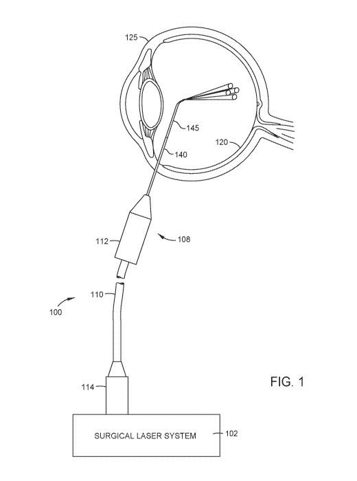
[0010] FIG. 1 illustrates an example system for creating a multi-spot
pattern of laser beams,
in accordance with certain aspects of the present disclosure.
[0011] FIG. 2 illustrates an example of a surgical laser system, and the
components therein,
used for creating a multi-spot pattern of laser beams, in accordance with
certain aspects of the
present disclosure.
[0012] FIG. 3 illustrates an example input of the surgical laser system of
FIG. 2 into an
interface plane of the proximal end of a cable that is coupled to the surgical
laser system, in
accordance with certain aspects of the present disclosure.
[0013] FIG. 4 illustrates an example of a surgical laser system, with two
diffraction optical
elements (DOEs), used for creating a multi-spot pattern of laser beams, in
accordance with certain
aspects of the present disclosure.
[0014] FIG. 5 illustrates an example input of the surgical laser system of
FIG. 4 into an
interface plane of the proximal end of a cable that is coupled to the surgical
laser system, in
accordance with certain aspects of the present disclosure.
[0015] FIG. 6 illustrates an example DOE having three segments, in
accordance with certain
aspects of the present disclosure.
[0016] To facilitate understanding, identical reference numerals have been
used, where
possible, to designate identical elements that are common to the drawings. It
is contemplated that
elements and features of one embodiment may be beneficially incorporated in
other embodiments
without further recitation.
CA 03139801 2021-11-09
WO 2020/245705 PCT/IB2020/055032
4
DETAILED DESCRIPTION
[0017] Aspects of the present disclosure provide a surgical laser system
configured to align
multi-wavelength laser beams with the cores of a multi-core fiber.
[0018] FIG. 1 illustrates an example system 100 for creating a multi-spot
pattern of laser beams
on the surface of the retina, according to certain embodiments of the present
invention. System
100 includes a surgical laser system 102 having one or more laser sources for
generating laser
beams used during ophthalmic procedures. For example, a first laser source
within surgical laser
system 102 may generate a treatment beam with a first wavelength (e.g., ¨532
nanometers (nm))
while a second laser source may generate an aiming beam with a second
wavelength (e.g., ¨635
nm). A user, such as a surgeon, may trigger the surgical laser system 102
(e.g., via a foot switch,
voice commands, etc.) to emit the aiming beam onto a desired retinal spot.
Once the surgeon has
positioned the laser probe so as to illuminate the desired retinal spot with
the aiming beam, the
surgeon activates the treatment beam, such as through a foot pedal or other
means, to treat the
targeted patient anatomy (e.g., photocoagulate the desired retinal spot using
the treatment beam).
[0019] As shown, surgical laser system 102 includes a connector or port
adapter 114 that
couples to an optical port (not shown) of surgical laser system 102. FIG. 1
also shows a cable 110
having a distal end that couples to and extends through a probe 108 and a
proximal end that couples
to and extends through port adapter 114. In the example of FIG. 1, port
adapter 114 includes a
ferrule with an opening that allows laser beams from surgical laser system 102
to be propagated
into an interface plane (also referred to as a proximal entrance plane) of the
proximal end of cable
110. The interface plane of cable 110 comprises the exposed proximal ends of
the one or more
cores where laser beams may be directed to. In the example of FIG. 1, cable
110 is a multi-core
optical fiber cable (MCF) with four cores. As such, the interface plane of the
proximal end of
cable 110 comprises the proximal ends of the four cores that are exposed
through the opening of
the ferrule of port adapter 114.
[0020] Surgical laser system 102 may be configured to split a single laser
beam that is
generated by a laser source into multiple laser beams that exhibit a laser
spot pattern. For example,
surgical laser system 102 may split a single aiming beam into four aiming
beams and then deliver
the four aiming beams to the interface plane of cable 110 through the opening
of the ferrule of port
adapter 114. Surgical laser system 102 may further be configured to split a
single treatment beam
CA 03139801 2021-11-09
WO 2020/245705 PCT/IB2020/055032
into four treatment beams and deliver the four treatment beams to the
interface plane of cable 110
through the opening of the ferrule. In such an example, each of the cores of
cable 110 would then
be transmitting both an aiming beam and a treatment beam, which may be
referred to, collectively,
as a combined beam or a multi-wavelength beam (due to the fact that the aiming
beam and
treatment beam have different wavelengths). In some examples, surgical laser
system 102 may
also propagate an illumination beam into an interface plane of cable 110
(e.g., which may also
include a proximal end of a cladding that holds the cores within cable 110) in
order to illuminate
the inside of the eye, especially areas of the retina 120 that are to be
photocoagulated. In certain
aspects, an illumination beam may be generated by a white light-emitting diode
(LED).
[0021] Cable 110 delivers the combined beams to probe 108, which propagates
a multi-spot
pattern (e.g., four spots) of combined beams to the retina 120 of a patient's
eye 125. Probe 108
includes a probe body 112 at its proximal end and a probe tip 140 at its
distal end. Probe body
112 and probe tip 140 house and protect the distal end of cable 110. A distal
end portion 145 of
the probe tip 140 may also contain a lens that focuses the combined beams on
the retina 120.
[0022] Various systems can be employed to create a multi-spot pattern of
combined laser
beams. FIG. 2 illustrates one example of a surgical laser system, and the
components therein, that
may be used for creating a multi-spot pattern of combined laser beams.
Surgical laser system 202
comprises a laser source 204, which generates a treatment beam 210, a laser
source 206, which
generates an aiming beam 212, and a light source 208, which generates an
illumination beam 214.
[0023] At the outset of the surgery, a surgeon may activate light source
208 in order to
illuminate the inside of the eye's globe and make it easier to view the
retina. As shown, once
emitted by light source 208, illumination beam 214 is received by collimating
lens 222, which is
configured to produce a beam with parallel (collimated) rays of light. In
certain embodiments,
collimating lens 222 may be a multi-element achromat comprising two singlet
lenses and one
doublet lens. Therefore, as shown, illumination beam 214 emerges with parallel
rays of light from
the other side of collimating lens 222 and passes through beam splitter 226 to
reach a condensing
lens 224. In certain embodiments, condensing lens 224 may be a multi-element
achromat
comprising two singlet lenses and one doublet lens. In such embodiments,
condensing lens 224
has the same exact design as collimating lens 222, except that the assembly is
revered (e.g., rotated
by 180 degrees), thereby creating a one-to-one magnification imaging system.
Beam splitter 226
CA 03139801 2021-11-09
WO 2020/245705 PCT/IB2020/055032
6
may have different coatings on its two sides, 226a and 226b. For example, side
226a is coated
such that it allows light propagated thereon to pass through beam splitter
226. As such,
illumination beam 214, which is propagated onto side 226a passes beam splitter
226. On the other
hand, side 226b is coated to reflect light or laser beams such as treatment
beam 210 and aiming
beam 212, as further described below. Although, note that a trivial portion of
illumination beam
214 is reflected by side 226a onto sensor 227, which is configured to sense
illumination beam 214.
[0024] Condensing lens 224 then converges illumination beam 214 into an
interface plane of
a proximal end of a cable, such as cable 110 shown in FIG. 1, that is coupled
to a port 225 of
surgical laser system 202 through port adapter 114. As described in relation
to FIG. 1, cable 110
is a cable with four cores. As such, condensing lens 224 focuses illumination
beam 214 into an
interface plane of cable 110 such that illumination beam 214 is propagated,
along an entire length
of each of the four cores of cable 110, to the distal end of a surgical probe
(e.g., probe 108 of FIG.
1) that is coupled to cable 110. As described above, the interface plane of
cable 110 comprises the
proximal ends of the four cores of cable 110 that are exposed through an
opening 217 of ferrule
215 of port adapter 114.
[0025] Once the surgeon is able to view inside the eye's globe, the surgeon
may project from
the distal end of the probe one or more desired aiming beam spots onto the
retina. More
specifically, after activation by the surgeon, laser source 206 emits aiming
beam 212 onto beam
splitter 218, which reflects aiming beam 212 onto diffraction optical element
(DOE) 220. As
further described in relation to FIG. 6, DOE 220 may comprise different
diffraction segments (e.g.,
three segments), each configured to diffract or split a beam into a different
number of beams. A
diffraction segment may also be referred to as a "segment" herein. In the
example of FIG. 2, DOE
220 is positioned such that aiming beam 212 is aligned with the middle segment
of DOE 220,
which diffracts aiming beam 212 into aiming beams (e.g., four aiming beams).
However, a
surgeon may change the position of DOE 220 in order to diffract a beam into a
different number
of beams (e.g., one or two). For example, using voice command or some other
feature of surgical
laser system 202, a surgeon may position DOE 220 to align aiming beam 212 with
a different
segment of DOE 220, which may diffract aiming beam 212 into one, two, or other
numbers of
beams.
CA 03139801 2021-11-09
WO 2020/245705 PCT/IB2020/055032
7
[0026] Once diffracted, the resulting aiming beams are reflected by beam
splitter 226 onto
condensing lens 224. Condensing lens 224 then focuses the four aiming beams
onto the interface
plane of a proximal end of cable 110 such that each of the aiming beams is
propagated, along an
entire length of a corresponding core of cable 110, to the distal end of a
surgical probe (e.g., probe
108 of FIG. 1). This allows the surgeon to project from the distal end of the
probe four desired
aiming beam spots onto the retina.
[0027] As described above, once the surgeon has positioned and activated
the laser probe so
as to project one or more aiming beam spots onto the retina, the surgeon may
then activate laser
source 204, such as through a foot pedal or other means, to treat the targeted
patient anatomy (e.g.,
photocoagulate the desired retinal spot using the treatment beam). When
activated, laser source
204 emits polarized treatment beam 210, whose polarization axis may be changed
by a polarization
rotator 232. For example, in some embodiments, polarization rotator 232
filters treatment beam
210 to produce a vertically-polarized treatment beam which is s-polarized
relative to the plane of
incidence of beam splitter 226.
[0028] A polarized treatment beam 210 may be advantageous because, in some
embodiments,
beam splitter 226 may have coatings that are sensitive to polarization such
that, for example, an s-
polarized beam may reflect off of beam splitter 226 with less broadening of
the wavelength. As
described above, beam splitter 226 is coated such that it allows illumination
beam 214 to pass
through while reflecting treatment beam 210 and aiming beam 212. Therefore, to
provide the
surgeon with a high quality and throughput illumination beam 214, it is
advantageous to polarize
treatment beam 210, which allows beam splitter 226 to isolate and reflect
treatment beam 210 with
a narrower band of wavelength.
[0029] Once polarized, treatment beam 210 reaches beam splitter 213, which
is configured to
allow a substantial portion of treatment beam 210 to pass through, while
reflecting a trivial portion
231 onto sensor 223. Sensor 223 is a light sensor configured to detect whether
laser source 204 is
active or not. After passing through beam splitter 213, treatment beam 210 is
received at beam
splitter 219, which is configured to reflect treatment beam 210 onto beam
splitter 218. Beam
splitter 218 is configured to reflect a trivial portion 233 of treatment beam
210 onto sensor 216
while allowing a substantial portion of treatment beam 210 to pass through.
Sensor 216 is a light
sensor configured to detect whether treatment beam 210 has reached beam
splitter 218.
CA 03139801 2021-11-09
WO 2020/245705 PCT/IB2020/055032
8
[0030] As shown, linearly polarized treatment beam 210 passes through beam
splitter 218 at
an angle with respect to beam splitter 218 that is equal to the angle with
which aiming beam 212
is reflected by beam splitter 218. Therefore, once laser source 204 is active,
transmitted treatment
beam 210 and reflected aiming beam 212 are combined (e.g., such that they
overlay each other),
creating combined beam 211, before reaching DOE 220. DOE 220 then diffracts
combined beam
211 into combined beams 211a-211d. Each one of combined beams 211a-211d refers
to a
diffracted treatment beam and a diffracted aiming beam that overlay each
other.
[0031] Combined beams 211a-211d are then received at beam splitter 226,
which reflects
combined beams 211a-211d onto condensing lens 224. Condensing lens 224 focuses
combined
beams 211a-211d onto an interface plane of the proximal end of cable 110 such
that each of the
combined beams 211a-211d is propagated, along an entire length of a
corresponding core of cable
110, to the distal end of a surgical probe (e.g., probe 108 of FIG. 1). More
specifically, in the
example of FIG. 2, cable 110 is an MCF with four cores, such as cores A, B, C,
and D. In such an
example, condensing lens 224 focuses combined beams 211a-211d onto an
interface plane of a
proximal end of cable 110 such that, for example, combined beam 211a is
propagated onto core
A, combined beam 211b is propagated onto core B, combined beam 211c is
propagated onto core
C, and combined beam 211d is propagated onto core D.
[0032] In the example of FIG. 2, both aiming beam 212 and treatment beam
210 are diffracted
by the same DOE 220. However, in optics, the angle at which light is
diffracted by a DOE is
dependent upon the light's wavelength. This is because a DOE's diffraction
grating is generally
configured or tuned to diffract light at a certain angle only for a given
wavelength. In the example
of FIG. 2, DOE 220 may be tuned to ensure that any diffracted beam with a
wavelength ki, which
is equal to the wavelength of treatment beam 210 (e.g., ¨532 nanometers (nm)),
is diffracted at an
angle 01 with respect to the incident beam direction. Accordingly, DOE 220 is
effectively able to
diffract treatment beam 210 at angle 01 for each diffracted beam. But, because
aiming beam 212
has a different wavelength k2 (e.g., ¨635 nm), DOE 220 may diffract aiming
beam 212 at angle 02
with respect to the incident beam direction, which may be slightly different
than angle 01.
[0033] Diffracting treatment beam 210 and aiming beam 212 at different
diffraction angles,
however, may cause a misalignment among one or more of the diffracted beams,
as further shown
in FIG. 3. In addition, in the example of FIG. 2, the inter-spot power non-
uniformity of the major
CA 03139801 2021-11-09
WO 2020/245705 PCT/IB2020/055032
9
beams diffracted from DOE 220 may be minimized only for the wavelength of
treatment beam
210 because the DOE grating design of DOE 220 is only optimized for treatment
beam 201's
wavelength. Inter-spot power non-uniformity is the maximum individual-spot
power deviation
from the average power of the major beam spots. DOE 220, therefore, may able
to minimize the
inter-spot power non-uniformity across only the four diffracted treatment
beams but not across the
four diffracted aiming beams. In addition, DOE 220 being only tuned to the
wavelength of
treatment beam 210 may result in an out-of-order leakage of aiming beam 212.
In other words,
DOE 220 may diffract aiming beam 212 into undesired spots, including the zero-
order spot which
is the portion of the incident beam that transmits, undiffracted, directly
through DOE 220.
[0034] The angular deviation (02 ¨ 01) between each diffracted beam 211a-d
at the aiming
beam wavelength and its corresponding diffracted beam 211a-d at the treatment
wavelength is
Fourier-transformed by condensing lens 224 into a spatial deviation r2 ¨ ri of
the spatial lateral
position of each diffracted aiming beam 212a-d on interface plane 340 and its
corresponding
treatment beam 210-a-d on interface plane 340, such as in the example
misalignment of FIG. 3
More specifically, FIG. 3 illustrates input into an interface plane 340 of the
proximal end of cable
110, which is exposed through an opening 217 of ferrule 215. Interface plane
340, as described
above, comprises the exposed proximal ends of the four cores 344a-344d of the
MCF cable 110
that extend through port adapter 114. As shown, because DOE 220 diffracts
treatment beam 210
and aiming beam 212 at different angles, aiming beam 212a is not aligned with
the center of
treatment beam 210a, which may correspond to the center of core 344a. As a
result, aiming beam
212a is not centered in core 344a. Note that the other three combined beams
211b-211d are not
shown in FIG. 3 for simplicity.
[0035] In the case of surgical laser system 202, the tolerance stack-up of
lateral misalignments
of the overall laser/probe optical system may cause one or more aiming beams
212a-d at interface
plane 340 to not couple fully into its respective fiber core 334, while other
aiming beams 212a-d
may fully couple into their respective fiber cores. This may greatly increase
the inter-spot power
non-uniformity of the multiple aiming beams 212a-d projected out of the probe
and focused onto
the retina. As such, one or more of the aiming beam spots projected on the
retina may be dim
relative to the other spots, which may be irritating or distracting to the
surgeon. Further, the
misalignment between the treatment beam and the aiming beam significantly
reduces the allowed
CA 03139801 2021-11-09
WO 2020/245705 PCT/IB2020/055032
margin for any further misalignment that may occur due to an optical drift or
other types of
environmental conditioning and/or perturbations. As such, any further
misalignment of an already
misaligned pair of treatment and aiming beams may further reduce the accuracy
of the
corresponding surgical laser system.
[0036] Accordingly, certain embodiments of the present disclosure relate to
a surgical laser
system that is configured to diffract a treatment beam and an aiming beam such
that each of the
diffracted aiming beams (e.g., four diffracted aiming beams) is aligned more
closely with each of
the corresponding diffracted treatment beams (e.g., four diffracted treatment
beams).
[0037] FIG. 4 illustrates an example surgical laser system 402 that may be
used for creating a
multi-spot pattern of combined laser beams. Surgical laser system 402
comprises a laser source
204, which generates a treatment beam 210, a laser source 206, which generates
an aiming beam
412, and a light source 208, which generates an illumination beam 214.
Surgical laser system 402
also comprises DOE 220, which is tuned to diffract laser beams with a
wavelength of ki (e.g.,
treatment beam 210), at an angle 01. Surgical laser system 402 also comprises
DOE 421, which
is tuned to diffract laser beams with a wavelength of 22 (e.g., aiming beam
412), at the same angle
01. Utilizing two DOEs allows surgical laser system 402 to diffract treatment
beam 210 and
aiming beam 412 both at the same angle and, thereby, ensure that the combined
beams are aligned
closely. As shown, surgical laser system 402 also comprises two different beam
splitters 226 and
427, one to reflect beams diffracted by DOE 220 and another to reflect beams
diffracted by DOE
421.
[0038] When activated by the surgeon, laser source 206 emits aiming beam
412, which is
diffracted by DOE 421 at angle 01, into aiming beams 412a-412d. Aiming beams
412a-412d then
reflect off of beam splitter 427 onto condensing lens 224. As described above,
beam splitter 226
is coated such that light propagated onto side 226a is able to pass through
beam splitter 226. As
such, aiming beams 412a-412d are able to efficiently transmit through beam
splitter 226 without
any change to their angular directions in the collimated-space region before
lens 224, or their
angles of incidence onto interface plane 340 in FIG. 5. The angle of incidence
refers to an angle
which an incident line or ray makes with a line perpendicular to the surface
at the point of
incidence. Condensing lens 224 then focuses aiming beams 412a-412d onto an
interface plane of
a proximal end of cable 110 such that each of the aiming beams 412a-412d is
propagated, along
CA 03139801 2021-11-09
WO 2020/245705 PCT/IB2020/055032
11
an entire length of a corresponding core of cable 110, to the distal end of a
surgical probe (e.g.,
probe 108 of FIG. 1).
[0039] Once the surgeon has illuminated the desired retinal spots with
aiming beams 412a-
412d, the surgeon activates laser source 204, which then emits treatment beam
210. Treatment
beam 210 may take the same path described in relation to FIG. 2 and reach DOE
220, which is
configured to diffract treatment beam 210, at the same angle 01, into
treatment beams 210a-210d.
Treatment beams 210a-210d then reflect off of beam splitter 226 onto
condensing lens 224, which
focuses treatment beams 210a-210d onto the interface plane of the proximal end
of cable 110 such
that each of the treatment beams 210a-210d is propagated, along an entire
length of a
corresponding core of cable 110, to the distal end of a surgical probe (e.g.,
probe 108 of FIG. 1).
[0040] As shown in FIG. 4, because the path of treatment beam 210 is
decoupled from the path
of aiming beam 412 (at least before they are reflected by beam splitters 427
and 226), the
diffraction angles for the two beams 210 and 412, which have different
wavelengths, can be the
same or even changed independent of each other. As described above, what
enables this
configuration is the use of two DOEs 220 and 421. As shown, both DOEs 220 and
421 are
configured or positioned to diffract beams 210 and 412 into the same number of
beams. In the
example of FIG. 4, both DOEs 220 and 421 are positioned such that beams 210
and 412 are aligned
with the middle segments of both DOEs 220 and 421, which are configured to
diffract each of
beams 210 and 412, respectively, into four beams. However, in some
embodiments, a surgeon
may cause both DOEs 220 and 421 to be repositioned such that beams 210 and 412
are diffracted
into another number of diffracted beams (e.g., one or two). Repositioning DOEs
220 and 421, in
some embodiments, may involve mechanically or electromechanically moving the
location of
DOEs 220 and 421 within surgical laser system 402. In certain embodiments,
both DOEs 220 and
421 may be mounted on the same linear element (e.g., a carriage or stage (not
shown)) such that
by repositioning the linear element, both DOEs 220 and 421 are set to the same
desired segment
at the same time.
[0041] Note that, in certain embodiments, DOE 220 and 421 may instead be
placed in a parallel
manner with respect to each other. In such embodiments, DOE 220 and 421 are
placed such that
each respective segment of DOE 220 is aligned with a respective segment of DOE
421. For
example, the DOE 220 and 421 may be stacked (e.g., vertically or horizontally)
on top of one
CA 03139801 2021-11-09
WO 2020/245705 PCT/IB2020/055032
12
another. In such embodiments, DOE 220 diffracts treatment beam 210 into a
number of diffracted
treatment beams (e.g., one, two, four) and DOE 421 diffracts aiming beam 412
into the same
number of diffracted aiming beams. Further, in such embodiments, DOE 220 and
421 would
diffract treatment beam 210 and aiming beam 212, respectively, onto a single
beam splitter, which
then reflects the diffracted treatment beams and the diffracted aiming beams
onto a condensing
lens. For example, the single beam splitter may be designed to have two narrow-
spectral-band
high-reflectance notches, one for reflecting the diffracted treatment beams
and one for reflecting
the diffracted aiming beams. Further, the single beam splitter may be tall
enough (e.g., vertically)
to simultaneously reflect the diffracted aiming beams and the diffracted
treatment beams to the
condensing lens, which then focuses each of the treatment beams and its
corresponding aiming
beam to the interface plane of cable 110.
[0042] FIG. 5 illustrates an example input into an interface plane 340 of
the proximal end of
cable 110, which is exposed through an opening 217 of ferrule 215. Because
DOEs 220 and 421
are configured to diffract treatment beam 210 and aiming beam 412,
respectively, at the same
angle, the center of aiming beam 412a is now aligned with the center of
treatment beam 210a,
which may correspond to the center of core 344a. Note that the combination of
aiming beam 412a
and treatment beam 210a corresponds to combined beam 511a. The other three
combined beams
are not shown for simplicity. Because aiming beams 412a-d are more centered in
treatment beams
210a-d, such as partly shown in FIG. 5, the inter-spot uniformity across the
aiming beams 212a-d
is increased. In addition, surgical laser system 402 has a higher margin for
any potential
misalignment that may be caused due to an optical drift or other types of
environmental
conditioning and/or perturbations. Also, because the inter-spot power non-
uniformity of DOE
220 is minimized by optimizing its grating design for the wavelength of
treatment beam 210 and
the inter-spot power non-uniformity of DOE 421 is minimized by optimizing its
grating design for
the wavelength of aiming beam 412, the beam power uniformity across the four
diffracted
treatment beams and the four diffracted aiming beams can be optimized. Using
DOE 421, which
is tuned to the wavelength of aiming beam 412, also reduces the out-of-order
leakage of aiming
beam 412.
[0043] Further, surgical laser system 402 has a higher angular stability
and is less prone to
misalignment, as compared to surgical laser system 202, because beam splitter
218 no longer
CA 03139801 2021-11-09
WO 2020/245705 PCT/IB2020/055032
13
reflects aiming beam 412. Generally, alignment sensitivity is much higher for
reflection than for
transmission. Since beam splitter 218 of surgical laser system 402 is only
used for transmission
of laser beams (i.e., treatment beam 210), it is not a major source of
potential beam angular stability
and alignment. Because even if environmental conditioning and/or perturbations
cause slight
misalignments to beam splitter 218, the angle at which treatment beam 210 is
transmitted may not
be significantly impacted. In surgical laser system 202, however, beam
splitter 218 is used for
both reflection (i.e., reflection of aiming beam 212) and transmission (i.e.,
transmission of
treatment beam 210). As such, any small misalignment of beam splitter 218 may
significantly
impact the angle with which aiming beam 212 is reflected. In addition, the
arrangement of
components in surgical laser system 402, allows for a more optimal placement
of sensor 227. As
shown in FIG. 5, sensor 227 is placed such that it is less likely to receive
any scattered light from
treatment beam 210. Sensor 227 may be sensitive to green light (e.g.,
treatment beam 210) when
attempting to sense the presence of white light (e.g., illumination beam 214)
and, therefore, by
receiving scattered light from treatment beam 210, sensor 227 may mistakenly
determine the
presence of illumination beam 214. For example, the placement of sensor 227 in
surgical laser
system 202 is such that it may receive some of the scattered light from the
diffracted treatment
beams 210a-d and incorrectly detect the presence of illumination beam 214.
[0044] FIG. 6 illustrates an example DOE 620 having three segments 660,
662, and 664. DOE
620 is similar to DOEs 220 and 421 in terms of the number of segments it has.
As shown, a beam
666 is diffracted by segment 660 into one beam while the same beam 666 is
diffracted by segment
662 into four beams. Segment 664 diffracts beam 666 into two beams.
[0045] A user, such as a surgeon, may select a desired number of beams to
be propagated from
a probe. For example, the surgeon may select four treatment beams to be
propagated from the
probe. The surgeon's selection is received at the surgical laser system (e.g.,
surgical laser system
102, 202, or 402) as input into the system's central processing unit (CPU).
The CPU may then be
configured to execute a certain set of instructions that are stored in the
system's memory, which
cause the system to position the system's DOE(s) based on the surgeon's
selection. In the example
of DOEs 421 and 220, the processor may cause an electromechanical motor to
move a carriage on
which DOEs 421 and 220 are mounted to ensure that aiming beam 212 and
treatment beam 210
CA 03139801 2021-11-09
WO 2020/245705 PCT/IB2020/055032
14
are aligned with segments of DOEs 421 and 220, respectively, that are
configured to diffract the
beams into four diffracted beams.
[0046] The foregoing description is provided to enable any person skilled
in the art to practice
the various embodiments described herein. Various modifications to these
embodiments will be
readily apparent to those skilled in the art, and the generic principles
defined herein may be applied
to other embodiments. Thus, the claims are not intended to be limited to the
embodiments shown
herein, but are to be accorded the full scope consistent with the language of
the claims.