Note: Descriptions are shown in the official language in which they were submitted.
CA 03139843 2021-11-09
Rechargeable battery cell
Description
The invention relates to a rechargeable battery cell having an S02-based
electrolyte.
Rechargeable battery cells are of great importance in many technical fields.
They are of-
ten used for applications which require only small rechargeable battery cells
having rela-
io tively low current intensities, for example, for the operation of cell
phones. In addition,
there is also a great need for larger rechargeable battery cells for high-
energy applica-
tions, with mass storage of energy in the form of battery cells being of
particular im-
portance for the electric propulsion of vehicles.
High energy density is an important requirement for these types of
rechargeable battery
cells. This means that the rechargeable battery cell should contain as much
electrical en-
ergy as possible per unit weight and volume. Lithium has proven to be
particularly advan-
tageous as an active metal for this purpose. Lithium is the metal having the
lowest atomic
number and therefore having the largest theoretical specific capacity of 3.884
mAh/g. It is
the most electronegative metal (-3.10 V vs. standard hydrogen electrode,
abbr.: SHE),
zo thereby generating the highest possible cell voltage with respect to a
given positive elec-
trode. It is also the lightest metal (0.54 g/cm3), which contributes to the
highest possible
gravimetric energy density (Wh/Kg) or specific energy density (Wh/L).
The active metal of a rechargeable battery cell is the metal whose ions within
the electro-
lyte migrate to the negative or positive electrode when the cell is being
charged or dis-
charged and participate in electrochemical processes there. These
electrochemical pro-
cesses lead directly or indirectly to the release of electrons into the
external circuit or to
the absorption of electrons from the external circuit. Rechargeable battery
cells compris-
ing lithium as the active metal of the negative electrode are also referred to
as lithium
cells.
The positive electrodes of lithium cells are designed as insertion electrodes.
The term "in-
sertion electrode" in the sense of the present invention refers to electrodes
which have a
crystal structure into which ions of the active material can be stored and
removed during
operation of the lithium cell. This means that the electrode processes can
take place not
only on the surface of the electrode, but also within the crystalline
structure. The positive
electrode, for example, consists of lithium cobalt oxide (LiCo02). When
charging the lith-
- 1 -
Date recue / Date received 2021-11-09
CA 03139843 2021-11-09
ium cell, the ions of the active metal are removed from the positive electrode
and depos-
ited in the negative electrode as metallic lithium. The reverse process takes
place when
the lithium cell is discharged.
The electrolyte is also an important functional element of every rechargeable
battery cell.
It usually comprises a solvent or a solvent blend and at least one conducting
salt. Solid
electrolytes or ionic liquids, for example, do not comprise a solvent, but
only the conduct-
ing salt. The electrolyte is in contact with the positive and negative
electrodes of the bat-
tery cell. At least one ion of the conducting salt (anion or cation) is
sufficiently mobile in
the electrolyte such that a charge transport between the electrodes, required
for the func-
io tioning of the rechargeable battery cell, can take place through ionic
conduction. The elec-
trolyte is oxidatively electrochemically decomposed from a certain upper cell
voltage of the
rechargeable battery cell. This process often leads to an irreversible
destruction of the
electrolyte components, and thus to a failure of the rechargeable battery
cell. Reductive
processes can also decompose the electrolyte when falling below a certain cell
voltage. In
order to avoid these processes, the positive and negative electrodes are
chosen such that
the cell voltage is below or above the decomposition voltage of the
electrolyte. The elec-
trolyte thus determines the voltage window, in the range of which a
rechargeable battery
cell can be operated reversibly, that is, repeatedly charged and discharged.
The lithium cells known from the prior art comprise an electrolyte consisting
of an organic
zo solvent or solvent blend and a conducting salt dissolved therein. The
conducting salt is a
lithium salt such as lithium hexafluorophosphate (LiPF6). The solvent blend
can comprise,
for example, ethylene carbonate. The electrolyte LP57, which has the
composition 1 M
LiPP6 in EC (ethylene carbonate) : EMC (ethyl methyl carbonate) 3:7, is an
example of
such an electrolyte. Due to the organic solvent or solvent blend, these kinds
of lithium
cells are also referred to as organic lithium cells.
Unintentional overcharging of organic lithium cells leads to irreversible
decomposition of
electrolyte components. The oxidative decomposition of the organic solvent
and/or the
conducting salt takes place on the surface of the positive electrode. The
reaction heat
generated during this decomposition and the resulting gaseous products are
responsible
for the subsequent so-called "thermal runaway" and the resulting destruction
of the or-
ganic lithium cell. The vast majority of charging protocols for these organic
lithium cells
use the cell voltage as an indicator of the end of charging. Accidents caused
by a thermal
runaway are particularly likely to occur when using multi-cell battery packs
in which a plu-
rality of organic lithium cells having dissimilar capacities are connected in
series.
- 2 -
Date recue / Date received 2021-11-09
CA 03139843 2021-11-09
Also this reductive decomposition of the organic electrolyte of a lithium cell
on the nega-
tive electrode is irreversible. No organic solvents are thermodynamically
stable with re-
spect to lithium or with respect to lithium which is stored in carbon (Li1C6).
However, many
solvents form a passivation film on the electrode surface of the negative
electrode. This
film spatially separates the solvent from the electrode, but is ionically
conductive and thus
enables the passage of lithium ions. The passivation film, the so-called
"Solid Electrolyte
Interphase" (SEI), gives stability to the system, by which the production of
lithium cells is
made possible. Lithium is integrated into the passivation film during the
formation of the
SEI. This process is irreversible and is therefore observed as a loss of
capacity.
io This irreversible loss of capacity, also referred to as the coating
layer capacity, depends
on the electrolyte formulation and the electrodes used. In organic lithium
cells, the electro-
lyte decomposition and formation of layers comprising lithium ions often
continues during
further operation of the lithium cell and is responsible for the loss of
capacity and thus for
a shorter service life of the cell. Capacity losses can also occur during the
storage of
charged lithium cells. This so-called self-discharge can be based on both
irreversible pro-
cesses (electrolyte decomposition) and reversible processes in which the
lithium stored in
the negative electrode is transferred to the electrolyte solution and is
available again the
next time it is charged.
Organic lithium cells are therefore problematic in terms of their stability
and long-term op-
erational reliability. Safety risks are also caused in particular by the
flammability of the or-
ganic solvent or solvent blend. When an organic lithium cell catches fire or
even explodes,
the metallic lithium forms a highly reactive substance and the organic solvent
in the elec-
trolyte forms a combustible material. Additional measures must be taken to
avoid such
safety risks.
A further development known from prior art therefore provides for the use of
an electrolyte
based on sulfur dioxide (SO2) instead of an organic electrolyte for
rechargeable battery
cells. Rechargeable battery cells, which comprise an S02-based electrolyte,
exhibit,
among other things, high ionic conductivity. The term "502-based electrolyte"
refers to an
electrolyte which comprises SO2 not merely as an additive at low
concentrations, but in
which the mobility of the ions in the conducting salt, which is comprised in
the electrolyte
and which causes the charge transport, is at least in part, largely or even
completely en-
sured by SO2. The SO2 thus serves as a solvent for the conducting salt. The
conducting
salt can form a liquid solvate complex with the gaseous SO2, whereby the SO2
is bound
and the vapor pressure is noticeably reduced compared to the pure SO2.
Electrolytes hav-
ing low vapor pressure are produced. Compared to the organic electrolytes
described
- 3 -
Date recue / Date received 2021-11-09
CA 03139843 2021-11-09
above, these S02-based electrolytes have the advantage of being non-
combustible.
Safety risks, which might occur due to the electrolyte's flammability, can
thus be excluded.
The use of metallic lithium as the negative electrode active material in
rechargeable cells
poses various problems. Lithium does not deposit uniformly during charging,
but rather in
the form of dendrites. The uncontrollable lithium dendrite growth leads to an
accumulation
of a highly reactive metal having a large surface area and can lead to safety-
critical states.
The thermodynamic instability of metallic lithium causes irreversible and
continuous reac-
tions between said lithium and the electrolyte. As a result, unintentionally
thick passivation
layers (SEI), which consume lithium and electrolyte components, are created on
the lith-
io .. ium metal surface. This increases the internal resistance, and the
service life of the lithium
cell is shortened. Large volumetric and morphological changes can occur in the
lithium
metal anode with repeated charging and discharging. The SEI films mentioned
are too un-
stable to completely suppress such significant changes.
Solutions to the above-mentioned problems in connection with a metallic
lithium anode
are being sought both in lithium cells having organic electrolyte solutions
and in battery
cells having the S02-based electrolyte.
The authors of the document [V1]
"Dendrite-Free Lithium Deposition Induced by Uniformly Distributed Lithium
Ions for Effi-
cient Lithium Metal Batteries"
Xin-Bing Cheng, Tin g-Zheng Hou, Rui Zhang, Hon g-Jie Peng, Chen-Zi Zhao,
Jia-Qi Huang and Qiang Zhang
Adv. Mater. 2016, 28, 2888-2895
report on a lithium metal battery having an organic electrolyte. A 3D glass
fiber fabric hav-
ing a large number of polar groups is used for the deposition of lithium to
obtain a den-
drite-free lithium metal anode.
US 7,901,811 B2 (hereinafter referred to as [V2]) describes a lithium metal
cell having an
S02-based electrolyte having the conducting salt lithium tetrachloroaluminate
(LiAIC14). In
order to avoid the disadvantages of dendritic deposition, a porous structure
formed from
solid particles is proposed, the structure being designed and arranged such
that the lith-
ium deposited during charging of the lithium metal cell penetrates from the
surface of the
discharger into the pores of the porous structure and is deposited again
there.
- 4 -
Date recue / Date received 2021-11-09
CA 03139843 2021-11-09
A disadvantage that also occurs, among other things, with these 502-based
electrolytes is
that any hydrolysis products formed in the presence of residual amounts of
water react
with the cell components of the rechargeable battery cell and thus lead to the
formation of
undesired by-products. Because of this, in the manufacture of such
rechargeable battery
cells having an S02-based electrolyte, attention should be paid to minimizing
the residual
water content comprised in the electrolyte and the cell components.
A further problem with S02-based electrolytes is that many conducting salts,
in particular
also known for organic lithium cells, are not soluble in SO2. Measurements
showed that
io SO2 is a poor solvent for many conducting salts, such as lithium
fluoride (LiF), lithium bro-
mide (LiBr), lithium sulfate (Li2SO4), lithium bis(oxalato)borate (LiBOB),
lithium hex-
afluoroarsenate (LiAsF6), lithium tetrafluoroborate (LiBF4), trilithium
hexafluoroaluminate
(Li3AIF6), lithium hexafluoroantimonate (Li5bF6), lithium
difluoro(oxalato)borate
(LiBF2C204), lithium bis(trifluoromethanesulfonyl)imide (LiTFS1), lithium
metaborate
(LiB02), lithium aluminate (LiA102), lithium triflate (LiCF3S03) and lithium
chlorosulfonate
(Li5O3C1). The solubility of these conducting salts in SO2 is approx. 10-2 -
10-4 mol/L (see
Table 1). With these low salt concentrations, it can be assumed that there are
at most only
low conductivities, which are not sufficient for the useful operation of a
rechargeable bat-
tery cell.
Table 1: Solubility of various salts in SO2
Conducting salt Solubility / mol/L in Conducting salt
Solubility / mol/L in
SO2 SO2
LiF 2.1.10-3 LiPF6 1.5-10-2
LiBr 4.9.10-3 LiSbF6 2.8.10-4
LI2SO4 2.710-4 LiBF2(C204) 1.4.10-4
LiB(C204)2 3.2.10-4 CF3S02NLiS02CF3 1.5.10-2
Li3PO4 LiB02 2.6.10-4
Li3AIF6 2.3.10-3 LiA102 4.3.10-4
LiBF4 1.7.10-3 LiCF3S03 6.3.10-4
LiAsF6 1.4.10-3
In order to further improve the possible uses and properties of rechargeable
battery cells
that comprise an S02-based electrolyte, the object of the present invention is
to specify a
- 5 -
Date recue / Date received 2021-11-09
rechargeable battery cell having an 502-based electrolyte, which, compared to
the re-
chargeable battery cells known from the prior art
- exhibits improved electrical performance data, in particular high energy
density;
- has a stable coating layer on the negative electrode, whereby the coating
layer ca-
pacity should be low and no further reductive electrolyte decomposition should
oc-
cur on the negative electrode during further operation;
- comprises an S02-based electrolyte, which contributes to the
deposition of metallic
lithium being as uniform as possible;
- comprises an S02-based electrolyte which exhibits good solubility for
conducting
salts and is therefore a good ion conductor and electronic insulator, so that
ion
transport can be facilitated and self-discharge can be reduced to a minimum;
- comprises an S02-based electrolyte that is also inert to other components
of the
rechargeable battery cell, such as separators, electrode materials and cell
packag-
ing materials;
- is resistant against various misuses such as electrical, mechanical or
thermal;
- comprises an S02-based electrolyte, which exhibits an increased
stability against
residual amounts of water in the cell components of rechargeable battery
cells;
- has a wide electrochemical window, so that no oxidative electrolyte
decomposition
occurs at the positive electrode;
- exhibits improved overcharging and deep discharging and less self-discharge
and
- shows an increased service life, in particular a high number of usable
charge and
discharge cycles.
Such rechargeable battery cells should, in particular, also have very good
electrical en-
ergy and performance data, high operational reliability and service life, in
particular a large
number of usable charge and discharge cycles, without the electrolyte
decomposing dur-
ing operation of the rechargeable battery cell.
A rechargeable battery cell according to the invention comprises an active
metal, at least
one positive electrode having a discharge element, at least one negative
electrode having
- 6 -
Date Recue/Date Received 2023-03-07
CA 03139843 2021-11-09
a discharge element, a housing and an electrolyte. The negative electrode
comprises me-
tallic lithium as an active material, at least in the charged state of the
rechargeable battery
cell.
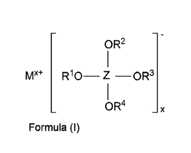
The electrolyte is based on SO2 and comprises at least one first conducting
salt. Said first
conducting salt has the formula (I).
- - OR2 _
1
Mx+ R10 ____________________________________ Z __ OR3
1
_ OR4 -x
Formula (I)
In formula (I), M is a metal selected from the group formed by alkali metals,
alkaline earth
metals, metals of group 12 of the periodic table of the elements and aluminum.
x is an in-
teger from 1 to 3. The substituents R1, R2, R3 and R4 are selected
independently of one
another from the group formed by C1-C10 alkyl, C2-Clo alkenyl, C2-Clo alkynyl,
C3-Clo cy-
cloalkyl, C6-C14 aryl and C5-C14 heteroaryl. The central atom Z is either
aluminum or bo-
ron.
The 502-based electrolyte used in the rechargeable battery cell according to
the invention
comprises SO2 not only as an additive in low concentration, but in
concentrations at which
zo the mobility of the ions of the first conducting salt, which is
comprised in the electrolyte
and causes the charge transport, is at least partially, largely or even
completely ensured
by the SO2. The first conducting salt is dissolved in the electrolyte and
shows very good
solubility therein. It can form a liquid solvate complex with the gaseous SO2,
in which the
SO2 is bound. In this case, the vapor pressure of the liquid solvate complex
is noticeably
reduced compared to the pure SO2, producing electrolytes that have a low vapor
pres-
sure. However, it is also within the scope of the invention that, depending on
the chemical
structure of the first conducting salt according to formula (I), no reduction
in vapor pres-
sure can occur in the production of the electrolyte according to the
invention. In the last-
mentioned case, it is preferred for the production of the electrolyte
according to the inven-
- 7 -
Date recue / Date received 2021-11-09
CA 03139843 2021-11-09
tion to be carried out at low temperature or under pressure. The electrolyte
may also com-
prise a plurality of conducting salts of the formula (I), which differ from
one another in their
chemical structure.
In the sense of the present invention, the term "Ci-Cio alkyl" includes linear
or branched
saturated hydrocarbon groups having one to ten carbon atoms. These include, in
particu-
lar, methyl, ethyl, n-propyl, isopropyl, n-butyl, sec-butyl, iso-butyl, tert-
butyl, n-pentyl, iso-
pentyl, 2,2-dimethylpropyl, n-hexyl, iso-hexyl, 2-ethylhexyl, n-heptyl, iso-
heptyl, n-octyl,
iso-octyl, n-nonyl, n-decyl and the like.
io In the sense of the present invention, the term "C2-Clo alkenyl"
includes unsaturated linear
or branched hydrocarbon groups having two to ten carbon atoms, wherein the
hydrocar-
bon groups have at least one C-C double bond. These include, in particular,
ethenyl, 1-
propenyl, 2-propenyl, 1-n-butenyl, 2-n-butenyl, isobutenyl, 1-pentenyl, 1-
hexenyl, 1-hep-
tenyl, 1-octenyl, 1-nonenyl, 1-decenyl and the like.
.. In the sense of the present invention, the term "C2-C10 alkynyl" includes
unsaturated linear
or branched hydrocarbon groups having two to ten carbon atoms, wherein the
hydrocar-
bon groups have at least one C-C triple bond. This includes, in particular,
ethynyl, 1-
propynyl, 2-propynyl, 1-n-butynyl, 2-n-butynyl, isobutynyl, 1-pentynyl, 1-
hexynyl, 1-hep-
tynyl, 1-octynyl, 1-nonynyl, 1-decynyl, and the like.
zo In the sense of the present invention, the term "C3-Cio cycloalkyl"
includes cyclic, satu-
rated hydrocarbon groups having three to ten carbon atoms. These include, in
particular,
cyclopropyl, cyclobutyl, cyclopentyl, cyclohexyl, cycloheptyl, cyclohexyl,
cyclononyl and
cyclodecanyl.
In the sense of the present invention, the term "C6-C14 aryl" includes
aromatic hydrocarbon
groups having six to fourteen ring carbon atoms. This includes, in particular,
phenyl (C61-15
group), naphthyl (C10H7 group) and anthracyl (C14F19 group).
In the sense of the present invention, the term "C5-C14 heteroaryl" includes
aromatic hy-
drocarbon groups having five to fourteen ring hydrocarbon atoms in which at
least one hy-
drocarbon atom is replaced by a nitrogen, oxygen or sulfur atom. These
include, in partic-
ular, pyrrolyl, furanyl, thiophenyl, pyrridinyl, pyranyl, thiopyranyl and the
like. All of the hy-
drocarbon groups mentioned above are each bonded to the central atom according
to for-
mula (I) via the oxygen atom.
A rechargeable battery cell having such an electrolyte has the advantage over
rechargea-
ble battery cells having electrolytes known from the prior art in that the
first conducting salt
comprised therein has higher oxidation stability and consequently shows
essentially no
- 8 -
Date recue / Date received 2021-11-09
CA 03139843 2021-11-09
decomposition at higher cell voltages. Said electrolyte is resistant to
oxidation, preferably
at least up to an upper potential of 4.0 volts, more preferably at least up to
an upper po-
tential of 4.2 volts, more preferably at least up to an upper potential of 4.4
volts, more pref-
erably at least up to an upper potential of 4.6 volts, more preferably at
least up to an upper
potential of 4.8 volts and most preferably at least up to an upper potential
of 5.0 volts.
Thus, when using such an electrolyte in a rechargeable battery cell, there is
little or no
electrolyte decomposition within the working potentials, that is, in the range
between the
end-of-charge voltage and the end-of-discharge voltage of both electrodes of
the re-
chargeable battery cell. As a result, rechargeable battery cells according to
the invention
io can have an end-of-charge voltage of at least 4.0 volts, more preferably
of at least 4.4
volts, more preferably of at least 4.8 volts, more preferably of at least 5.2
volts, more pref-
erably of at least 5.6 volts and most preferably of at least 6.0 volts.
The service life of the rechargeable battery cell comprising this electrolyte
is significantly
longer than that of rechargeable battery cells comprising electrolytes known
from the prior
art.
Furthermore, a rechargeable battery cell having such an electrolyte is also
resistant to low
temperatures. At a temperature of -40 C, for example, 61% of the charged
capacity can
still be discharged. The conductivity of the electrolyte at low temperatures
is sufficient to
operate a battery cell.
zo Furthermore, a rechargeable battery cell having such an electrolyte
exhibits increased sta-
bility with respect to residual amounts of water. If there are still small
residual amounts of
water in the electrolyte (in the range of ppm), the electrolyte or the first
conducting salt
forms hydrolysis products with the water, which products, compared to the S02-
based
electrolytes known from the prior art, are significantly less aggressive
towards the cell
components. Because of this, the absence of water in the electrolyte plays a
less im-
portant role in S02-based electrolytes in comparison to those known from the
prior art.
These advantages of the electrolyte according to the invention outweigh the
disadvantage
that arises from the fact that the first conducting salt according to formula
(I) has a signifi-
cantly larger anion size than the conducting salts known from the prior art.
This higher an-
ion size leads to a lower conductivity of the first conducting salt according
to formula (I)
compared to the conductivity of LiAIC14.
- 9 -
Date recue / Date received 2021-11-09
CA 03139843 2021-11-09
Negative electrode
The active material of the negative electrode is metallic lithium. This means
that lithium is
also the active metal of the rechargeable battery. Said lithium is deposited
on the dis-
charge element of the negative electrode when the rechargeable battery cell is
charged.
This means that the negative electrode also comprises a discharge element in
addition to
the metallic lithium. This discharge element serves to enable the required
electronically
conductive connection of the active material of the negative electrode. For
this purpose,
the discharge element is in contact with the active material involved in the
electrode reac-
io tion of the negative electrode. When the rechargeable battery cell is
discharged, the me-
tallic lithium is converted into lithium ions, wherein the lithium ions
migrate from the nega-
tive electrode to the positive electrode. If the positive electrode is
designed as an interca-
lation electrode, the lithium ions in the uncharged state of the battery cell
are located at
least partly in a host matrix of the active material of the positive
intercalation electrode.
Advantageous developments of the rechargeable battery cell according to the
invention
with regard to the negative electrode are described below:
An advantageous development of the rechargeable battery cell according to the
invention
zo provides that the electronically conductive discharge element of the
negative electrode is
free of metallic lithium in the discharged state of the rechargeable battery
cell. Metallic lith-
ium is deposited on the electronically conductive discharge element of the
negative elec-
trode when charging the battery cell. The metallic lithium is essentially
completely dis-
solved when discharging and enters the host matrix of the active material of
the positive
.. electrode in the form of ions.
A further advantageous development of the battery cell according to the
invention provides
that the electronically conductive discharge element of the negative electrode
already
comprises metallic lithium before the first charging of the rechargeable
battery cell occurs.
Further metallic lithium is deposited on the electronically conductive
discharge element
when the battery cell is charged. The metallic lithium is completely or only
partially dis-
solved when discharging and enters the host matrix of the active material of
the positive
electrode in the form of ions. On the one hand, the metallic lithium, which is
already lo-
cated on the discharge element, can be applied to the discharge element before
the bat-
tery cell is assembled, and can be built into the battery cell together with
it. On the other
- 10 -
Date recue / Date received 2021-11-09
CA 03139843 2021-11-09
hand, the metallic lithium can be deposited on the discharge element of the
negative elec-
trode before the battery cell is operated, that is, before the first charging
and discharging
by a preceding initialization charging process.
A further advantageous development of the battery cell according to the
invention provides
that the electronically conductive discharge element of the negative electrode
is free of
metallic lithium before the battery cell is charged for the first time.
Metallic lithium is depos-
ited on the electronically conductive discharge element when the battery cell
is charged.
The metallic lithium is completely or only partially dissolved when
discharging and enters
.. the host matrix of the active material of the positive electrode in the
form of ions.
A further advantageous development of the battery cell according to the
invention pro-
vides that the discharge element of the negative electrode is at least
partially formed from
a lithium-storing material. In such a development, when the battery cell is
being charged,
part of the lithium resulting from the electrode reaction is initially stored
in the electroni-
cally conductive discharge element made of the lithium-storing material. As
the battery cell
continues to be charged, metallic lithium is then deposited on the
electronically conductive
discharge element. The metallic lithium is completely or only partially
dissolved when dis-
charging and enters the host matrix of the active material of the positive
electrode in the
zo form of ions.
The lithium-storing material can, for example, be the insertion material
carbon, in particu-
lar in the form of the carbon allotrope graphite. It can also be a material
which forms an
alloy with lithium, such as lithium-storing metals and metal alloys (for
example, Si, Ge, Sn,
Sr1C0xCy, SnSix and the like, here preferably silicon) or oxides of lithium-
storing metals
and metal alloys (for example, SnOx, SiOx, oxidic glasses of Sn, Si and the
like) or a lith-
ium intercalation material that does not comprise carbon, such as lithium
titanates, in par-
ticular Li4Ti5012. Conversion materials such as transition metal oxides can
also be used as
lithium-storing materials.
A further advantageous development of the battery cell according to the
invention pro-
vides that the discharge element of the negative electrode is designed as a
planar dis-
charge element in the form of a thin metal sheet or a thin metal foil. The
thin metal foil
preferably has a perforated or mesh-like structure. The planar discharge
element can also
consist of a plastic film coated with metal. Said metal coatings have a
thickness in the
range from 0.1 pm to 20 pm. The active material of the negative electrode is
preferably
- 11 -
Date recue / Date received 2021-11-09
CA 03139843 2021-11-09
applied to the surface of the thin metal sheet, the thin metal foil or the
metal-coated plastic
foil. The active material can be applied to the front and/or the rear side of
the planar dis-
charge element. Such planar discharge elements have a thickness in the range
from 5 pm
to 50 pm. A thickness of the planar discharge element in the range from 10 pm
to 30 pm
is preferred. When using planar discharge elements, the negative electrode can
have a
total thickness of at least 20 pm, preferably at least 40 pm and particularly
preferably at
least 60 pm. The maximum thickness is at most 200 pm, preferably at most 150
pm and
particularly preferably at most 100 pm. The area-specific capacity of the
negative elec-
trode based on the coating on one side is preferably at least 0.5 mAh/cm2 when
using a
io planar discharge element in the charged state of the battery cell,
wherein the following
values are further preferred in this order: 1 mAh/cm2, 3 mAh/cm2, 5 mAh/cm2,
mAh/cm2, 15 mAh/cm2, 20 mAh/cm2, 25 mAh/cm2.
Furthermore, there is also the possibility for the discharge element of the
negative elec-
trode to be designed three-dimensionally in the form of a porous metal
structure, in partic-
ular in the form of a metal foam. The term "three-dimensional porous metal
structure" re-
fers to any structure consisting of metal that not only extends over the
length and width of
the flat electrode like the thin metal sheet or the metal foil, but also over
its thickness di-
mension. The three-dimensional porous metal structure is sufficiently porous
such that the
zo active material of the negative electrode, that is, metallic lithium,
can be deposited into the
pores of the metal structure. The amount of active material deposited is the
loading on the
negative electrode. When the discharge element is designed three-dimensionally
in the
form of a porous metal structure, in particular in the form of a metal foam,
then the nega-
tive electrode preferably has a thickness of at least 0.2 mm, more preferably
at least 0.3
mm, more preferably at least 0.4 mm, more preferably at least 0.5 mm and most
prefera-
bly at least 0.6 mm. In this case, the thickness of the electrodes is
significantly greater
compared to negative electrodes used in organic lithium cells. A further
advantageous
embodiment provides that the area-specific capacity of the negative electrode
in the
charged state of the battery cell when using a three-dimensional discharge
element, in
particular in the form of a metal foam, is preferably at least 2.5 mAh/cm2,
wherein the fol-
lowing values are further preferred in this order: 5 mAh/cm2, 15 mAh/cm2, 25
mAh/cm2,
mAh/cm2, 45 mAh/cm2
A further advantageous development of the battery cell according to the
invention pro-
35 vides that the discharge element includes a binder. Said binder is
preferably a fluorinated
- 12 -
Date recue / Date received 2021-11-09
CA 03139843 2021-11-09
binder, in particular a polyvinylidene fluoride and/or a terpolymer which is
formed from tet-
rafluoroethylene, hexafluoropropylene and vinylidene fluoride. However, it can
also be a
binder which consists of a polymer which is composed of monomeric structural
units of a
conjugated carboxylic acid or of the alkali, alkaline earth or ammonium salt
of this conju-
gated carboxylic acid or of a combination thereof. Furthermore, the binder can
also con-
sist of a polymer based on monomeric styrene and butadiene structural units.
In addition,
the binder can also be a binder from the group of carboxymethyl celluloses.
The binder is
present in the negative electrode, preferably in a concentration of at most
20% by weight,
more preferably at most 15% by weight, more preferably at most 10% by weight,
more
io preferably at most 7% by weight, more preferably at most 5% by weight
and most prefera-
bly at most 2% by weight based on the total weight of the negative electrode.
Electrolyte
Advantageous developments of the rechargeable battery cell with regard to the
SO2-
based electrolyte are described below.
In a further advantageous embodiment of the rechargeable battery cells, the
substituents
R1, rc"2,
R3 and R4 of the first conducting salt are selected independently of one
another
zo from the group formed by
¨ Cl-C6 alkyl; preferably from C2-C4 alkyl; particularly preferably from
the alkyl
groups 2-propyl, methyl and ethyl;
¨ C2-C6 alkenyl; preferably from C2-C4 alkenyl; particularly preferably
from the
alkenyl groups ethenyl and propenyl;
¨ C2-C6 alkynyl; preferably from C2-C4 alkynyl;
¨ C3-C6 cycloalkyl;
¨ phenyl; and
¨ C6-C7 heteroaryl.
In the case of this advantageous embodiment of the S02-based electrolyte, the
term "Ci-
C6 alkyl" includes linear or branched saturated hydrocarbon groups having one
to six hy-
drocarbon groups, in particular methyl, ethyl, n-propyl, isopropyl, n-butyl,
sec-butyl, iso-
- 13 -
Date recue / Date received 2021-11-09
CA 03139843 2021-11-09
butyl, tert-butyl, n-pentyl, iso-pentyl, 2,2-dimethylpropyl, n-hexyl and iso-
hexyl. C2-C4 al-
kyls are preferred among these. The C2-C4 alkyls 2-propyl, methyl and ethyl
are particu-
larly preferred.
In the case of this advantageous embodiment of the S02-based electrolyte, the
term "C2-
C6 alkenyl" includes unsaturated linear or branched hydrocarbon groups having
two to six
carbon atoms, wherein the hydrocarbon groups have at least one C-C double
bond.
These include in particular ethenyl, 1-propenyl, 2-propenyl, 1-n-butenyl, 2-n-
butenyl, iso-
butenyl, 1-pentenyl and 1-hexenyl, wherein C2-C4 alkenyls are preferred.
Ethenyl and 1-
propenyl are particularly preferred.
io In the case of this advantageous embodiment of the S02-based
electrolyte, the term "C2-
C6 alkynyl" includes unsaturated linear or branched hydrocarbon groups having
two to six
carbon atoms, wherein the hydrocarbon groups have at least one C-C triple
bond. These
include in particular ethynyl, 1-propynyl, 2-propynyl, 1-n-butynyl, 2-n-
butynyl, iso-butynyl,
1-pentynyl and 1-hexynyl. Preferred among these are C2-04 alkynyls.
.. In the case of this advantageous embodiment of the S02-based electrolyte,
the term "C3-
C6 cycloalkyl" includes cyclic saturated hydrocarbon groups having three to
six carbon at-
oms. These include in particular cyclopropyl, cyclobutyl, cyclopentyl and
cyclohexyl.
In the case of this advantageous embodiment of the S02-based electrolyte, the
term "C6-
C7 heteroaryl" includes phenyl and naphthyl.
To improve the solubility of the first conducting salt in the S02-based
electrolytes, the sub-
stituents R1, R2, R3 and R4 are substituted, in a further advantageous
embodiment of the
rechargeable battery cell, by at least one fluorine atom and/or by at least
one chemical
group, wherein the chemical group is selected from the group formed by C1-C4
alkyl, C2-C4
alkenyl, C2-C.4 alkynyl, phenyl and benzyl. The chemical groups Cl-C4 alkyl,
C2-C4 alkenyl,
C2-C4 alkynyl, phenyl and benzyl have the same properties or chemical
structures as the
hydrocarbon groups described above. Substituted in this context means that
individual at-
oms or groups of atoms of the substituents R1, R2, R3 and R4 have been
replaced by the
fluorine atom and/or by the chemical group.
A particularly high solubility of the first conducting salt in the S02-based
electrolytes can
be achieved by at least one of the substituents R1, R2, R3 and R4 being a CF3
group or an
0502CF3 group.
In a further advantageous development of the rechargeable battery cell, the
first conduct-
ing salt is selected from the group formed by
- 14 -
Date recue / Date received 2021-11-09
CA 03139843 2021-11-09
-o
CF3
..(CF3 F3C CF
F3C 3
F3C
9 /¨CF3 0 cF, CF3
cF ,
Li o-e-o Li
Li 3 Al ="-1-0F3
F3C ¨/ 6) F3C b3 F3C ¨0 F3
0
)CF3 )c-CF3
CF3 F3C F3C CF3
Li[B(OCH2CF3)4] Li[B(OCH(CF3)2)4] Li[A1(0C(CF3)3)4]
- e
- e
HG
F3C34VCF3 F3C¨.(CF3
CFo CF3 0 CF3
LP '-'3"' L 3 Ai ' ¨(--CH3 LP z
F3C CF3 F3C 0 t CF3
0 0
)c-CF3
F3C CH3 F3C
Li[A1(0C(CH3)(CF3)2)4] Li[Al(OCH(CF3)2)4].
In order to adjust the conductivity and/or other properties of the electrolyte
to a desired
value, the electrolyte in a further advantageous embodiment of the
rechargeable battery
cell according to the invention has at least one second conducting salt
different from the
first conducting salt according to formula (I). This means that, in addition
to the first con-
ducting salt, the electrolyte can comprise a or even further second conducting
salts which
differ from the first conducting salt in their chemical composition and their
chemical struc-
ture.
In a further advantageous embodiment of the rechargeable battery cell
according to the
invention, the second conducting salt is an alkali metal compound, in
particular a lithium
compound. The alkali metal compound or the lithium compound are selected from
the
group formed by an aluminate, a halide, an oxalate, a borate, a phosphate, an
arsenate
and a gallate. The second conducting salt is preferably a lithium
tetrahaloaluminate, in
particular LiAIC14.
Furthermore, in a further advantageous embodiment of the rechargeable battery
cell ac-
cording to the invention, the electrolyte comprises at least one additive.
This additive is
zo preferably selected from the group formed by vinylene carbonate and its
derivatives, vi-
nylethylene carbonate and its derivatives, methylethylene carbonate and its
derivatives,
- 15 -
Date recue / Date received 2021-11-09
CA 03139843 2021-11-09
lithium (bisoxalato)borate, lithium difluoro(oxalato)borate, lithium
tetrafluoro(oxalato)phos-
phate, lithium oxalate, 2-vinylpyridine, 4-vinylpyridine, cyclic exomethylene
carbonates,
sultones, cyclic and acyclic sulfonates, acyclic sulfites, cyclic and acyclic
sulfinates, or-
ganic esters of inorganic acids, acyclic and cyclic alkanes, which acyclic and
cyclic al-
kanes have a boiling point of at least 36 C at 1 bar, aromatic compounds,
halogenated cy-
clic and acyclic sulfonylimides, halogenated cyclic and acyclic phosphate
esters, halogen-
ated cyclic and acyclic phosphines, halogenated cyclic and acyclic phosphites,
halogen-
ated cyclic and acyclic phosphazenes, halogenated cyclic and acyclic
silylamines, halo-
genated cyclic and acyclic halogenated esters, halogenated cyclic and acyclic
amides,
io halogenated cyclic and acyclic anhydrides and halogenated organic
heterocycles.
In relation to the total weight of the electrolyte composition, the
electrolyte has the follow-
ing composition in a further advantageous development of the rechargeable
battery cell:
(I) 5 to 99.4% by weight sulfur dioxide,
(ii) 0.6 to 95% by weight of the first conducting salt,
(iii) 0 to 25% by weight of the second conducting salt and
(iv) 0 to 10% by weight of the additive.
As already mentioned above, the electrolyte can comprise not only a first
conducting salt
zo according to formula (I) and a second conducting salt, but also a
plurality of first conduct-
ing salts according to formula (I) and a plurality of second conducting salts.
In the last-
mentioned case, the aforementioned percentages also include a plurality of
first conduct-
ing salts and a plurality of second conducting salts. The molar concentration
of the first
conducting salt lies in the range from 0.01 mol/L to 10 mol/L, preferably from
0.05 mol/L to
10 mol/L, more preferably from 0.1 mol/L to 6 mol/L and most preferably from
0.2 mol/L to
3.5 mol/L, based on the total volume of the electrolyte.
A further advantageous development of the rechargeable battery cell according
to the in-
vention provides that the electrolyte comprises at least 0.1 mol SO2,
preferably at least 1
MOI SO2, more preferably at least 5 mol SO2, more preferably at least 10 mol
SO2 and
most preferably at least 20 mol SO2 per mole of conducting salt. The
electrolyte can also
comprise very high molar proportions of SO2, wherein the preferred upper limit
value is
2600 mol SO2 per mole of conducting salt and upper limits of 1500, 1000, 500
and 100
mol of SO2 per mole of conducting salt are further preferred in this order.
The term "per
mole of conducting salt" refers to all conducting salts that are comprised in
the electrolyte.
- 16 -
Date recue / Date received 2021-11-09
CA 03139843 2021-11-09
Electrolytes based on SO2 having such a concentration ratio between SO2 and
the con-
ducting salt have the advantage in that they can dissolve a larger amount of
conducting
salt compared to the electrolytes known from the prior art, which are based,
for example,
on an organic solvent blend. In the context of the invention, it was found
that, surprisingly,
an electrolyte having a relatively low concentration of conducting salt is
advantageous de-
spite the associated higher vapor pressure, in particular with regard to its
stability over
many charge and discharge cycles of the rechargeable battery cell. The
concentration of
SO2 in the electrolyte affects its conductivity. Thus, by choosing the SO2
concentration,
the conductivity of the electrolyte can be adjusted to the planned use of a
rechargeable
io battery cell operated using this electrolyte.
The total content of SO2 and the first conducting salt can be greater than 50
percent by
weight (% by weight) of the weight of the electrolyte, preferably greater than
60% by
weight, more preferably greater than 70% by weight, more preferably greater
than 80% by
weight, more preferably greater than 85% by weight, more preferably greater
than 90% by
weight, more preferably greater than 95% by weight or most preferably greater
than 99%
by weight.
The electrolyte can comprise at least 5% by weight SO2 based on the total
amount of the
electrolyte comprised in the rechargeable battery cell, wherein values of 20%
by weight
zo SO2, 40% by weight SO2 and 60% by weight SO2 are more preferred. The
electrolyte can
also comprise up to 95% by weight SO2, wherein maximum values of 80% by weight
SO2
and 90% by weight SO2 are preferred in this order.
It is within the scope of the invention for the electrolyte to preferably have
only a small per-
or even no percentage of at least one organic solvent. The proportion of
organic
solvents in the electrolyte, which is present, for example, in the form of one
solvent or a
blend of a plurality of solvents, can preferably be at most 50% by weight of
the weight of
the electrolyte. Lower proportions of at most 40% by weight, at most 30% by
weight, at
most 20% by weight, at most 15% by weight, at most 10% by weight, at most 5%
by
weight or at most 1% by weight of the electrolyte weight are particularly
preferred. More
preferably, the electrolyte is free of organic solvents. Due to the low
proportion of organic
solvents or even their complete absence, the electrolyte is either hardly
combustible or not
at all combustible. This increases the operational safety of a rechargeable
battery cell op-
erated using such an S02-based electrolyte. The S02-based electrolyte is
particularly
preferably essentially free of organic solvents.
- 17 -
Date recue / Date received 2021-11-09
CA 03139843 2021-11-09
In relation to the total weight of the electrolyte composition, the
electrolyte has the follow-
ing composition in a further advantageous development of the rechargeable
battery cell:
(i) 5 to 99.4% by weight sulfur dioxide,
(ii) 0.6 to 95% by weight of the first conducting salt,
(iii) 0 to 25% by weight of the second conducting salt,
(iv) 0 to 10% by weight of the additive and
(v) 0 to 50% by weight of an organic solvent.
Positive electrode
Advantageous developments of the rechargeable battery cell according to the
invention
with regard to the positive electrode are described below:
An advantageous development of the rechargeable battery cell according to the
invention
provides that the positive electrode can be charged at least up to an upper
potential of 4.0
volts, preferably up to a potential of 4.4 volts, more preferably of at least
a potential of 4.8
volts, more preferably at least up to a potential of 5.2 volts, more
preferably at least up to
a potential of 5.6 volts and most preferably at least up to a potential of 6.0
volts.
zo In a further advantageous development of the rechargeable battery cell
according to the
invention, the positive electrode comprises at least one active material. Said
material can
store ions of the active metal and release and take up the ions of the active
metal during
operation of the battery cell.
In a further advantageous development of the rechargeable battery cell
according to the
invention, the positive electrode comprises at least one intercalation
compound. In the
sense of the present invention, the term "intercalation compound" refers to a
sub-category
of the insertion materials described above. Said intercalation compound acts
as a host
matrix, which has vacancies that are interconnected. The ions of the active
metal can dif-
fuse into these vacancies during the discharge process of the rechargeable
battery cell
and can be stored there. During the deposition of the ions of the active
metal, only minor
or no structural changes occur in the host matrix.
In a further advantageous development of the rechargeable battery cell
according to the
.. invention, the positive electrode comprises at least one conversion
compound as the ac-
- 18 -
Date recue / Date received 2021-11-09
CA 03139843 2021-11-09
tive material. In the sense of the present invention, the term "conversion
compounds" re-
fers to materials which form other materials during electrochemical activity;
that is, chemi-
cal bonds are broken and re-established during charging and discharging of the
battery
cell. Structural changes occur in the matrix of the conversion compound during
the ab-
sorption or release of the ions of the active metal.
In a further advantageous development of the rechargeable battery cell
according to the
invention, the active material has the composition LixMiyM"z08, wherein
¨ M' is at least one metal selected from the group formed by the elements Ti,
V, Cr,
Mn, Fe, Co, Ni, Cu and Zn;
¨ M" is at least one element selected from the group formed by the elements
of
groups 2, 3, 4, 5, 6, 7, 8, 9, 10, 11, 12, 13, 14, 15 and 16 of the periodic
table of
the elements;
¨ x and y independently of one another are numbers greater than 0;
¨ z is a number greater than or equal to 0; and
¨ a is a number greater than 0.
The indices y and z in the composition LixM'yM"z0, relate to the totality of
metals and ele-
ments that are represented by M' and M", respectively. If, for example, M'
comprises two
metals M" and M'2, the following applies to the index y: y=y1+y2, wherein y1
and y2 repre-
sent the indices of the metals M'1 and M'2. The indices x, y, z and a must be
chosen such
that there is charge neutrality within the composition. Examples of compounds
in which M'
comprises two metals are lithium nickel manganese cobalt oxides of the
composition
LixNi1Mny2Co,02 with M'1=Ni, M'2=Mn and M"=Co. Examples of compounds in which
z=0,
that is, which have no further metal or element M", are lithium cobalt oxides
LixCoy0a.
For example, if M" comprises two elements, on the one hand, a metal M"1 and on
the
other hand, phosphorus as M"2, the following applies to the index z: z=z1+z2,
wherein z1
and z2 represent the indices of the metal M"1 and of phosphorus (M"2). The
indices x, y, z
and a must be chosen such that there is charge neutrality within the
composition. Exam-
ples of compounds in which M" comprises a metal M"1 and phosphorus as M"2 are
lithium
iron manganese phosphates LixFeyMnz113,204 with M'=Fe, M"1=Mn and M"2=P and
z2=1.
In a further composition, M" can comprise two non-metals, for example,
fluorine as M"1
and sulfur as M"2. Examples of such compounds are lithium iron fluorosulfates
LixFeyFz1Sz204 with M'=Fe, M"1=F and M"2=P.
- 19 -
Date recue / Date received 2021-11-09
CA 03139843 2021-11-09
A further advantageous development of the rechargeable battery cell according
to the in-
vention provides that M' consists of the metals nickel and manganese and M" is
cobalt.
These can be compositions of the formula Li2NioMny2Co,02 (NMC), that is,
lithium nickel
manganese cobalt oxide having the structure of layered oxides. Examples of
these lithium
nickel manganese cobalt oxide active materials are LiNi1,3Mni/3Cov302
(NMC111),
LiNia6Mna2Coo.202 (NMC622) and LiNio.8Mno.1Coo.102 (NMC811). Further compounds
of
lithium nickel manganese cobalt oxide can have the composition
LiNia5Mna3Co0.202,
LiNia5Mno.25C00.2502, LiNi0.52Mno.32C00.1602, LiNi0.55Mno.30C00.1502,
LiNia58Mnat4C00.2802,
io LiNi0.6.4Mnal8Coo.1802, LiNi0.65Mno.27C00.0802, LiNia7Mno2Co0.102,
LiNia7Mno.15C00.1502,
LiNi0.72Mn0.10C00.1802, LiNiamMnai4C00.1002, LiNi0.86Mn0.04C00.1002,
LiNi0.90Mno.05Coo.o502,
LiNio_95Mno.025C00.02502 or a combination thereof. Positive electrodes for
rechargeable bat-
tery cells having a cell voltage of over 4.6 volts can be produced using these
compounds.
A further advantageous development of the rechargeable battery cell according
to the in-
vention provides that the active material is a metal oxide which is rich in
lithium and man-
ganese (lithium and manganese-rich oxide material). These materials can be
described
with the following formulas: Li8MnyM",08. M' of the formula Li,M'yM",0,
described above
thus represents the metal manganese (Mn). The index x here is greater than or
equal to 1,
the index y is greater than the index z or greater than the sum of the indices
z1+z2+z3
etc. For example, if M" comprises two metals M"1 and M"2 with the indices z1
and z2 (for
example, Li12Mno.525N10.175C00.102 with M"1=Ni z1=0.175 and M"2=Co z2=0.1),
the following
applies for the index y: y>z1+z2, The index z is greater than or equal to 0
and the index a
is greater than 0. The indices x, y, z and a must be chosen such that there is
charge neu-
trality within the composition. Metal oxides which are rich in lithium and
manganese can
also be described by the formula
mLi2MnO3-(1¨m)LiM'02 with 0 < m <1. Examples of such compounds are
Li12Mno.525Nio.175C00.102, Li1.2Mna6Nio.202 Or Lit2Niai3C00.13Mn0.5402.
A further advantageous development of the rechargeable battery cell according
to the in-
vention provides that the composition has the formula LixM'yM"z04. These
compounds are
spinel structures. For example, M' can be cobalt, and M" manganese. In this
case, the ac-
tive material is lithium cobalt manganese oxide (LiCoMn04). LiCoMn04 can be
used to
produce positive electrodes for rechargeable battery cells having a cell
voltage of over 4.6
volts. This LiCoMnat is preferably free of Mn. In a further example, M' can be
nickel and
M" can be manganese. In this case, the active material is lithium nickel
manganese oxide
- 20 -
Date recue / Date received 2021-11-09
CA 03139843 2021-11-09
(LiNiMn04). The molar proportions of the two metals M' and M" can vary.
Lithium nickel
manganese oxide can, for example, have the composition LiNia5Mn1.504.
In a further advantageous development of the rechargeable battery cell
according to the
invention, the positive electrode comprises at least one active material which
constitutes a
conversion compound. Conversion compounds undergo a solid-state redox reaction
dur-
ing the absorption of the active metal, for example, lithium or sodium, in
which the crystal
structure of the material changes. This occurs by breaking and recombining
chemical
bonds. Completely reversible reactions of conversion compounds can be, for
example, as
follows:
Type A: MX, H + y Li M + z Li(y,,)X
Type B: X < > + y Li LiyX
Examples of conversion compounds are FeF2, FeF3, CoF2, CuF2, NiF2, BiF3,
FeCl3, FeCl2,
CoCl2, NiCl2, CuC12, AgCI, LiCI, S, Li2S, Se, Li2Se, Te, I and Lil.
In a further advantageous development of the battery cell according to the
invention, the
compound has the composition Li8MlyMn171Nr2z204, wherein M"2 is phosphorus and
z2 has
the value 1. The compound having the composition Li8M'yM"1,1M"2,204 is a
lithium metal
phosphate. In particular, this compound has the composition Li2FeyMn2113,204.
zo Examples of lithium metal phosphates are lithium iron phosphate
(LiFePO4) or lithium iron
manganese phosphates (Li(FeyMn,)PO4). An example of a lithium iron manganese
phos-
phate is the phosphate of the composition Li(Fea3Mn0.7)PO4.
Lithium metal phosphates of other compositions can also be used for the
battery cell ac-
cording to the invention.
A further advantageous development of the rechargeable battery cell according
to the in-
vention provides that the positive electrode comprises at least one metal
compound. This
metal compound is selected from the group that is formed by a metal oxide, a
metal halide
and a metal phosphate. The metal of this metal compound is preferably a
transition metal
.. of the atomic numbers 22 to 28 of the periodic table of the elements, in
particular cobalt,
nickel, manganese or iron.
A further advantageous development of the rechargeable battery cell according
to the in-
vention provides that the positive electrode comprises at least one metal
compound which
has the chemical structure of a spine!, a layered oxide, a conversion compound
or a poly-
anionic compound.
- 21 -
Date recue / Date received 2021-11-09
CA 03139843 2021-11-09
It is within the scope of the invention for the positive electrode to comprise
at least one of
the compounds described or a combination of the compounds as the active
material. A
combination of the compounds refers to a positive electrode which comprises at
least two
of the materials described.
A further advantageous development of the battery cell according to the
invention pro-
vides that the positive electrode has a discharge element. This means that the
positive
electrode also comprises a discharge element in addition to the active
material. Said dis-
io charge element serves to enable the required electronically conductive
connection of the
active material of the positive electrode. For this purpose, the discharge
element is in con-
tact with the active material involved in the electrode reaction of the
positive electrode.
Said discharge element can be designed in a planar manner in the form of a
thin metal
sheet or a thin metal foil. The thin metal foil preferably has a perforated or
mesh-like struc-
ture. The planar discharge element can also consist of a plastic film coated
with metal.
Said metal coatings have a thickness in the range from 0.1 pm to 20 pm. The
active mate-
rial of the positive electrode is preferably applied to the surface of the
thin metal sheet, the
thin metal foil or the metal-coated plastic foil. The active material can be
applied to the
zo front and/or the rear side of the planar discharge element. Such planar
discharge ele-
ments have a thickness in the range from 5 pm to 50 pm. A thickness of the
planar dis-
charge element in the range from 10 pm to 30 pm is preferred. When using
planar dis-
charge elements, the positive electrode can have a total thickness of at least
20 pm, pref-
erably at least 40 pm and particularly preferably at least 60 pm. The maximum
thickness
is at most 200 pm, preferably at most 150 pm and particularly preferably at
most 100 pm.
The area-specific capacity of the positive electrode based on the coating on
one side is
preferably at least 0.5 mAh/cm2 when using a planar discharge element, wherein
the fol-
lowing values are further preferred in this order: 1 mAh/cm2, 3 mAh/cm2, 5
mAh/cm2,
10 mAh/cm2, 15 mAh/cm2, 20 mAh/cm2.
Furthermore, there is also the possibility for the discharge element of the
positive elec-
trode to be designed three-dimensionally in the form of a porous metal
structure, in partic-
ular in the form of a metal foam. The three-dimensional porous metal structure
is suffi-
ciently porous such that the active material of the positive electrode can be
incorporated
into the pores of the metal structure. The amount of active material
incorporated or ap-
plied is the loading on the positive electrode. When the discharge element is
designed
- 22 -
Date recue / Date received 2021-11-09
CA 03139843 2021-11-09
three-dimensionally in the form of a porous metal structure, in particular in
the form of a
metal foam, then the positive electrode preferably has a thickness of at least
0.2 mm,
more preferably at least 0.3 mm, more preferably at least 0.4 mm, more
preferably at least
0.5 mm and most preferably at least 0.6 mm. A further advantageous embodiment
pro-
s vides that the area-specific capacity of the positive electrode when
using a three-dimen-
sional discharge element, in particular in the form of a metal foam, is
preferably at least
2.5 mAh/cm2, wherein the following values are further preferred in this order:
5 mAh/cm2,
15 mAh/cm2, 25 mAh/cm2, 35 mAh/cm2, 45 mAh/cm2, 55 mAh/cm2, 65 mAh/cm2,
75 mAh/cm2. When the discharge element is designed three-dimensionally in the
form of a
io porous metal structure, in particular in the form of a metal foam, the
amount of active ma-
terial of the positive electrode, that is, the loading of the electrode, based
on its area, is at
least 10 mg/cm2, preferably at least 20 mg/cm2, more preferably at least 40
mg/cm2, more
preferably at least 60 mg/cm2, more preferably at least 80 mg/cm2 and most
preferably at
least 100 mg/cm2. This loading of the positive electrode has a positive effect
on the charg-
15 ing process and the discharging process of the rechargeable battery
cell.
In a further advantageous development of the battery cell according to the
invention, the
positive electrode has at least one binder. Said binder is preferably a
fluorinated binder, in
particular a polyvinylidene fluoride and/or a terpolymer which is formed from
tetrafluoro-
20 ethylene, hexafluoropropylene and vinylidene fluoride. However, it can
also be a binder
which consists of a polymer which is composed of monomeric structural units of
a conju-
gated carboxylic acid or of the alkali, alkaline earth or ammonium salt of
this conjugated
carboxylic acid or of a combination thereof. Furthermore, the binder can also
consist of a
polymer based on monomeric styrene and butadiene structural units. In
addition, the
25 binder can also be a binder from the group of carboxymethyl celluloses.
The binder is pre-
sent in the positive electrode, preferably in a concentration of at most 20%
by weight,
more preferably at most 15% by weight, more preferably at most 10% by weight,
more
preferably at most 7% by weight, more preferably at most 5% by weight and most
prefera-
bly at most 2% by weight based on the total weight of the positive electrode.
Structure of the rechargeable battery cell
Advantageous developments of the rechargeable battery cell according to the
invention
are described below with regard to their structure:
- 23 -
Date recue / Date received 2021-11-09
CA 03139843 2021-11-09
In order to further improve the function of the rechargeable battery cell, a
further advanta-
geous development of the rechargeable battery cell according to the invention
provides
that the rechargeable battery cell comprises a plurality of negative
electrodes and a plural-
ity of positive electrodes, which are stacked alternately in the housing.
Here, the positive
electrodes and the negative electrodes are preferably each electrically
separated from
one another by separators.
The separator can be formed from a non-woven material, a membrane, a woven
material,
a knitted material, an organic material, an inorganic material or a
combination thereof. Or-
ganic separators can consist of unsubstituted polyolefins (for example,
polypropylene or
ir) polyethylene), partially to completely halogen-substituted polyolefins
(for example, par-
tially to completely fluorine-substituted, in particular PVDF, ETFE, PTFE),
polyesters, pol-
yamides or polysulfones. Separators that comprise a combination of organic and
inorganic
materials are, for example, glass fiber textile materials in which the glass
fibers are pro-
vided with a suitable polymer coating. The coating preferably comprises a
fluorine-con-
taming polymer such as polytetrafluoroethylene (PTFE), ethylene-
tetrafluoroethylene
(ETFE), perfluoroethylene propylene (FEP), THV (terpolymer of
tetrafluoroethylene, hex-
afluoroethylene and vinylidene fluoride), a perfluoroalkoxy polymer (PFA),
aminosilane,
polypropylene or polyethylene (PE). The separator can also be folded in the
housing of
the rechargeable battery cell, for example, in the form of so-called "Z-
folding". In this Z-
folding, a strip-shaped separator is folded in a Z-like manner through or
around the elec-
trodes. Furthermore, the separator can also be formed as separator paper.
It is also within the scope of the invention for the separator to be able to
be designed as a
sheath, wherein each positive electrode or each negative electrode is
enveloped by the
sheath. The sheath can be formed from a non-woven material, a membrane, a
woven ma-
terial, a knitted material, an organic material, an inorganic material or a
combination
thereof.
A sheath on the positive electrode leads to more uniform ion migration and ion
distribution
in the rechargeable battery cell. The more even the ion distribution, in
particular in the
negative electrode, the higher the possible loading of the negative electrode
with active
material and, as a result, the usable capacity of the rechargeable battery
cell. At the same
time, risks are avoided that could be associated with uneven loading and the
resulting
deposition of the active metal. These advantages are particularly effective
when the posi-
tive electrodes of the rechargeable battery cell are enveloped in the sheath.
The surface dimensions of the electrodes and the sheath can preferably be
matched to
one another such that the external dimensions of the sheath of the electrodes
and the ex-
ternal dimensions of the unsheathed electrodes match at least in one
dimension.
- 24 -
Date recue / Date received 2021-11-09
CA 03139843 2021-11-09
The surface area of the sheath can preferably be greater than the surface area
of the
electrode. In this case, the sheath extends beyond a boundary of the
electrode. Two lay-
ers of the sheath covering the electrode on both sides can therefore be
connected to one
another at the edge of the positive electrode by an edge connection.
In a further advantageous embodiment of the rechargeable battery cell
according to the
invention, the negative electrodes have a sheath, while the positive
electrodes have no
sheath.
Further advantageous properties of the invention are described and explained
in more de-
w tail below on the basis of figures, examples and experiments.
Figure 1: shows a first embodiment of a rechargeable battery cell
according to the in-
vention in a cross-sectional illustration;
Figure 2: shows an electron microscope image of the three-dimensional
porous
structure of the metal foam of the first embodiment from Figure 1 as a de-
tailed illustration;
Figure 3: shows a second embodiment of a rechargeable battery cell
according to
the invention in a cross-sectional illustration;
Figure 4: shows a detail of the second embodiment from Figure 3;
Figure 5: shows a third embodiment of the rechargeable battery cell
according to the
invention in an exploded illustration;
Figure 6: shows the potential profile in volts [V] during two
charge/discharge cycles
as a function of the percentage charge of a test full cell having metallic
lith-
ium as the active material of the negative electrode, wherein the charge
and discharge current is 0.1 mA/cm2;
Figure 7: shows the potential profile in volts [V] during two
charge/discharge cycles
as a function of the percentage charge of a test full cell having metallic
lith-
ium as the active material of the negative electrode, wherein an
initialization
cycle was performed before the two charge/discharge cycles and the
charge and discharge current is 0.1 mA/cm2;
- 25 -
Date recue / Date received 2021-11-09
CA 03139843 2021-11-09
Figure 8: shows the potential profile in volts [V] during two
charge/discharge cycles
as a function of the percentage charge of a test full cell having metallic
lith-
ium as the active material of the negative electrode, wherein an external
pressure was applied to the cell, an initialization cycle was performed be-
fore the two charge/discharge cycles and the charge and discharge current
is 0.1 mA/cm2;
Figure 9: shows a negative electrode obtained after dismantling the
second test full
cell from Experiment 1;
Figure 10: shows the potential profile in volts [V] during two
charge/discharge cycles
as a function of the percentage charge of a test full cell having metallic
lith-
ium as the active material of the negative electrode, wherein an
initialization
cycle was performed before the two charge/discharge cycles and the
charge and discharge current is 0.5 mA/cm2;
Figure 11: shows the potential profile in volts [V] during two
charge/discharge cycles
as a function of the percentage charge of a test full cell having metallic
lith-
ium as the active material of the negative electrode, wherein an
initialization
cycle was performed before the two charge/discharge cycles and the
charge and discharge current is 1.0 mA/cm2;
Figure 12: shows the cycle efficiency in % as a function of the number of
cycles of a
test full cell having metallic lithium as the active material of the negative
electrode, wherein the charge and discharge current is 1.0 mA/cm2;
Figure 13: shows the cycle efficiencies in % as a function of the number
of cycles of
three test full cells having metallic lithium as the active material of the
nega-
tive electrode, wherein two test full cells comprised electrolyte 1 and one
test full cell comprised a reference electrolyte;
Figure 14: shows the conductivity in [mS/cm] of electrolyte 1 as a
function of the con-
centration of compound 1;
- 26 -
Date recue / Date received 2021-11-09
CA 03139843 2021-11-09
Figure 15: shows the conductivity in [mS/cm] of electrolyte 3 as a
function of the con-
centration of compound 3; and
Figure 16: shows the conductivity in [mS/cm] of electrolyte 4 as a
function of the con-
centration of compound 4.
Figure 1 shows a first embodiment of a rechargeable battery cell 2 according
to the inven-
tion in a cross-sectional illustration. Said rechargeable battery cell 2 is
designed as a pris-
matic cell and has a housing 1, among other things. Said housing 1 encloses an
electrode
io array 3 which comprises three positive electrodes 4 and four negative
electrodes 5. The
positive electrodes 4 and the negative electrodes 5 are stacked alternately in
the elec-
trode array 3. The housing 1 can, however, also accommodate more positive
electrodes 4
and/or negative electrodes 5. In general, it is preferred when the number of
negative elec-
trodes 5 is one greater than the number of positive electrodes 4. This has the
conse-
quence of the outer end faces of the electrode stack being formed by the
electrode sur-
faces of the negative electrodes 5. The electrodes 4, 5 are connected to
corresponding
contacts 9, 10 of the rechargeable battery cell 2 via electrode connections 6,
7. The re-
chargeable battery cell 2 is filled with an S02-based electrolyte such that
the electrolyte
penetrates as completely as possible into all pores or cavities, in particular
within the elec-
trodes 4, 5. The electrolyte is not visible in Figure 1. In the present
embodiment, the posi-
tive electrodes 4 comprise an intercalation compound as an active material.
This intercala-
tion compound is LiCoMn04.
The electrodes 4, 5 are designed flat in the present embodiment, that is, as
layers having
a thickness that is smaller in relation to their surface area. They are each
separated from
one another by separators 11. The housing 1 of the rechargeable battery cell 2
is essen-
tially designed as a rectangular parallelepiped, wherein the electrodes 4, 5
and the walls
of the housing 1 shown in a sectional illustration extend perpendicular to the
plane of the
drawing and are essentially straight and flat. The rechargeable battery cell 2
can, how-
ever, also be designed as a winding cell in which the electrodes consist of
thin layers that
are wound up together with a separator material. The separators 11, on the one
hand,
separate the positive electrode 4 and the negative electrode 5 spatially and
electrically
and, on the other hand, are permeable to the ions of the active metal, among
other things.
In this way, large electrochemically effective surfaces are created, which
enable a corre-
spondingly high current yield.
The electrodes 4, 5 also have a discharge element which serves to enable the
required
electronically conductive connection of the active material of the respective
electrode.
- 27 -
Date recue / Date received 2021-11-09
CA 03139843 2021-11-09
Said discharge element is in contact with the active material involved in the
electrode re-
action of the respective electrode 4, 5 (not depicted in Figure 1). The
discharge element is
designed in the form of a porous metal foam 18. The metal foam 18 extends over
the
thickness dimension of the electrodes 4, 5. The active material of the
positive electrodes 4
and the negative electrodes 5 is incorporated into the pores of said metal
foam 18 so that
it fills its pores uniformly over the entire thickness of the metal structure.
The positive elec-
trodes 4 comprise a binder to improve the mechanical strength. This binder is
a fluoropol-
ymer. The negative electrodes 5 comprise lithium as an active material.
Figure 2 shows an electron microscope image of the three-dimensional porous
structure
io of the metal foam 18 of the first embodiment from Figure 1. On the basis
of the specified
scale, it can be seen that the pores P have an average diameter of more than
100 pm,
that is, are relatively large. This metal foam is a metal foam made of nickel.
Figure 3 shows a second embodiment of a rechargeable battery cell 20 according
to the
invention in a cross-sectional illustration. Said second embodiment differs
from the first
embodiment shown in Figure 1 in that the electrode array comprises a positive
electrode
23 and two negative electrodes 22. They are each separated from one another by
separa-
tors 21 and surrounded by a housing 28. The positive electrode 23 has a
discharge ele-
ment 26 in the form of a planar metal foil, to which the active material 24 of
the positive
zo electrode 23 is applied on both sides. The negative electrodes 22 also
comprise a dis-
charge element 27 in the form of a planar metal foil, to which the active
material 25 of the
negative electrode 22 is applied on both sides. Alternatively, the planar
discharge ele-
ments of the edge electrodes, that is, of the electrodes that close off the
electrode stack,
can only be coated with active material on one side. The non-coated side faces
the hous-
ing wall. The electrodes 22, 23 are connected to corresponding contacts 31, 32
of the re-
chargeable battery cell 20 via electrode connections 29, 30.
Figure 4 shows the planar metal foil which serves as a discharge element 26,
27 for the
positive electrodes 23 and the negative electrodes 22 in the second embodiment
from Fig-
30 ure 3. This metal foil has a perforated or mesh-like structure having a
thickness of 20 pm.
Figure 5 shows a third embodiment of a rechargeable battery cell 40 according
to the in-
vention in an exploded illustration. This third embodiment differs from the
two embodi-
ments explained above in that the positive electrode 44 is enveloped by a
sheath 13. In
35 this case, a surface area of the sheath 13 is greater than a surface
area of the positive
electrode 44, the boundary 14 of which is shown in Figure 5 as a dashed line.
Two layers
- 28 -
Date recue / Date received 2021-11-09
CA 03139843 2021-11-09
15, 16 of the sheath 13 that cover the positive electrode 44 on both sides are
connected
to one another at the circumferential edge of the positive electrode 44 by an
edge connec-
tion 17. The two negative electrodes 45 are not enveloped. The electrodes 44
and 45 can
be contacted via the electrode connections 46 and 47.
Example 1: Preparation of a reference electrolyte
A reference electrolyte used for the examples described below was produced
according to
the method described in patent specification EP 2 954 588 B1 (hereinafter
referred to as
io [V3]). First, lithium chloride (LiCI) was dried under vacuum at 120 C
for three days. Alumi-
num particles (Al) were dried under vacuum for two days at 450 C. LiCI,
aluminum chlo-
ride (AIC13) and Al were mixed together in an AlC13:LiCI:Al molar ratio of
1:1.06:0.35 in a
glass bottle having an opening to allow gas to escape. This blend was
thereafter heat-
treated in stages to produce a molten salt. After cooling, the salt melt
formed was filtered,
then cooled to room temperature and finally SO2 was added until the desired
molar ratio of
SO2 to LiAIC14 was formed. The reference electrolyte thus formed had the
composition
LiAIC14* x SO2, wherein x is dependent on the amount of SO2 supplied.
Example 2: Preparation of four embodiments 1, 2, 3 and 4 of an S02-based
electrolyte for
zo a battery cell
Four embodiments 1, 2, 3 and 4 of the S02-based electrolyte were prepared for
the exper-
iments described below (hereinafter referred to as electrolytes 1, 2, 3 and
4). For this pur-
pose, four different first conducting salts according to formula (I) were
initially prepared us-
ing a manufacturing process described in the following documents [V4], [V5]
and [V6]:
[V4] õI. Krossing, Chem. Eur. J. 2001, 7, 490;
[V5] S. M. Ivanova et al., Chem. Eur. J. 2001, 7, 503;
[V6] Tsujioka et al., J. Electrochem. Soc., 2004, 151, A1418"
These four different, first conducting salts according to formula (I) are
referred to below as
compounds 1, 2, 3 and 4. They come from the family of
polyfluoroalkoxyaluminates and
were prepared in hexane according to the following reaction equation, starting
from LiAIH4
and the corresponding alcohol R-OH with R1=R2=R3=R4.
- 29 -
Date recue / Date received 2021-11-09
CA 03139843 2021-11-09
LiAIH4 + 4 HO-R Hexan > LiAl(OR)4 +
4 H2
As a result, compounds 1, 2, 3 and 4 shown below were formed using the sum and
struc-
tural formulas:
F3F4cF3
F3c"1143Z3F3 Li
Fsebo t K
kcF, -CFa
F,d tFli HeC CF3
F3 ...lie
e H3c CF3 4111.4Z3 -6'
F3PLO' t KEI3
)c
Fyd 'CFI3 F C 3
c3F3YF CF3
u H4 14.,10-i
F3C-- 'Crtl ' F3
Fd1siCF3
0
_ -
Li[A1(0C(CF3)3)4] Li[A1(0C(CH3)(CF3)2)4] Li[Al(OCH(CF3)2)4]
Compound 1 Compound 2 Compound 3
¨ ¨e
F3c¨(CF3
0 CF3
LP .,Ci.F.,3,,,, .,,0_(
F30 0 ), 0F3
0
F3C)----0F3
_1
Li[B(OCH(CF3)2)4]
Compound 4
Compounds 1, 2, 3 and 4 were first recrystallized for purification. As a
result, residues of
the educt LiAIH4 were removed from the first conducting salt, since said educt
could possi-
bly lead to the formation of sparks with possibly existing traces of water in
SO2.
Compounds 1, 2, 3 and 4 were then dissolved in SO2. It was found that
compounds 1, 2, 3
and 4 dissolve well in SO2.
The preparation of electrolytes 1, 2, 3 and 4 was performed at low temperature
or under
pressure according to process steps 1 to 4 listed below:
1) receiving of the respective compound 1, 2, 3 and 4 in a pressure
piston each
with a riser pipe,
- 30 -
Date recue / Date received 2021-11-09
CA 03139843 2021-11-09
2) evacuation of the pressure pistons,
3) inflow of liquid SO2 and
4) repetition of steps 2 + 3 until the target amount of SO2 was added.
The respective concentration of compounds 1, 2, 3 and 4 in electrolytes 1, 2,
3 and 4 was
0.6 mol/L (molar concentration based on 1 liter of the electrolyte), unless
otherwise de-
scribed in the description of the experiment. The experiments described below
were per-
formed using electrolytes 1, 2, 3 and 4 and the reference electrolyte.
io Example 3: Production of test full cells
The test full cells used in the experiments described below are rechargeable
battery cells
having two negative electrodes and one positive electrode, each separated by a
separa-
tor. The positive electrodes included an active material, a conductivity
mediator and a
binder. The active material of the positive electrode is named in the
respective experi-
ment. The negative electrodes comprised metallic lithium as the active
material, which
was deposited on the discharge element of the negative electrode or was
already present.
The discharge element of the positive and negative electrodes was made of
nickel. The
test full cells were each filled with the electrolyte required for the
experiments, that is, ei-
ther with the reference electrolyte or electrolytes 1, 2, 3 01 4.
Several, that is, two to four, identical test whole cells were produced for
each experiment.
The results presented in the experiments are each mean values from the
measured val-
ues obtained for the identical test full cells.
Example 4: Measurement in test full cells
Coating layer capacity:
The capacity consumed in the first cycle to form a coating layer on the
negative electrode
is an important criterion for the quality of a battery cell. This coating
layer is formed on the
negative electrode when the test full cell is charged for the first time.
Lithium ions are irre-
versibly consumed for this formation of a coating layer (coating layer
capacity), so that the
test full cell has less cyclic capacity available for the subsequent cycles.
The coating layer
capacity in % of the theory that was used to form the coating layer on the
negative elec-
trode is calculated according to the following formula:
- 31 -
Date recue / Date received 2021-11-09
CA 03139843 2021-11-09
Coating layer capacity [in % of the theory] = (Qtad (x mAh) ¨ Qent (y mAh)) /
QNEL
Qad describes the amount of charge specified in the respective experiment in
mAh; Qent
describes the amount of charge in mAh that was obtained when the test full
cell was sub-
s sequently discharged. QNEL is the theoretical capacity of the negative
electrode used. The
theoretical capacity is calculated, for example, in the case of graphite, to a
value of 372
mAh/g.
The nominal capacity is obtained by subtracting the coating layer capacity
(=aad (x mAh)
¨ Qent (y mAh)) from the theoretical capacity of the positive electrode.
Discharge capacity:
For measurements in test full cells, for example, the discharge capacity is
determined
from the number of cycles. For this purpose, the test full cells are charged
with a certain
charge current intensity up to a certain upper potential. The corresponding
upper potential
is held until the charge current has dropped to a certain value. The discharge
then takes
place with a certain discharge current intensity up to a certain discharge
potential. This
charging method is called I/U charging. This process is repeated depending on
the de-
sired number of cycles.
zo The upper potentials or the discharge potential and the respective
charge or discharge
current intensities are given in the experiments. The value to which the
charge current
must have dropped is also described in the experiments.
The term "upper potential" is used as a synonym for the terms "charge
potential", "charge
voltage", "end-of-charge voltage" and "upper potential limit". The terms
denote the volt-
age/potential up to which a cell or battery is charged with the aid of a
battery charger.
The battery is preferably charged at a current rate of C/2 and at a
temperature of 22 C.
With a charge or discharge rate of 1C, by definition, the nominal capacity of
a cell is
charged or discharged in one hour. A charge rate of C/2 means a charge time of
2 hours.
The term "discharge potential" is used synonymously with the term "lower cell
voltage".
This describes the voltage/potential up to which a cell or battery is
discharged with the aid
of a battery charger.
The battery is preferably discharged at a current rate of C/2 and at a
temperature of 22 C.
The discharge capacity is obtained from the discharge current and the time
until the crite-
ria for ending the discharge are fulfilled. The associated figures show mean
values for the
- 32 -
Date recue / Date received 2021-11-09
CA 03139843 2021-11-09
discharge capacities as a function of the number of cycles. These mean values
of the dis-
charge capacities are expressed as a percentage of the nominal capacity.
The ratio of the discharge capacity Qent and the charge capacity 0 ¨lad
results in the cycle
efficiency Z = / ¨ent 0 ¨lad. The charge capacity is specified by the
charge parameters. The
discharge capacity is determined for each cycle as described above.
Experiment 1: Cycles of test full cells using a charge and discharge current
of 0.1 mA/cm2
Experiments in test full cells according to Example 3 were performed using
metallic lithium
as an active material of the negative electrode. The test full cells were
filled with electro-
lyte 1 described in Example 2. The positive electrodes comprised lithium
nickel manga-
nese cobalt oxide as an active material. Two charge/discharge cycles were
performed and
the discharge capacities were determined. Two charge/discharge cycles were
performed
directly with the first test full cell. An initialization cycle was performed
with the second test
full cell before the two charge/discharge cycles. Metallic lithium was
deposited for 3 min at
12 mA and further until the end of the charge at 0.1 mA/cm2. This was followed
by a dis-
charge. The two charge/discharge cycles then started. The influence of
external pressure
was examined using the third test full cell. For this purpose, the housing of
the test full cell
was pressed together in a defined manner from the outside at a pressure of
approx. 50
N/cm2. An initialization cycle was then performed as described for the second
full test cell,
followed by two charge/discharge cycles. The test full cells were charged at a
current of
0.1 mA/cm2 up to a potential of 4.4 volts and until a charge capacity of 8
mAh/cm2 was
reached. The discharge then took place at a current of 0.1 mA/cm2 until a
potential of 2.9
volts was reached.
Figures 6, 7 and 8 each show the potential in volts of the three test full
cells during charg-
ing and discharging as a function of the charge in %, which is related to the
maximum
charge. The cycle efficiencies of the two cycles shown are also depicted for
each test full
cell in the figures.
All three test full cells show a similar potential profile in cycle 1 and
cycle 2. The cycle effi-
ciencies are over 90% for all test full cells and are somewhat better for the
test full cells in
which an initialization cycle was performed.
- 33 -
Date recue / Date received 2021-11-09
CA 03139843 2021-11-09
Experiment 2: Morphology of lithium deposition
The second test full cell from Experiment 1 was dismantled after a few cycles
to determine
the morphology of the deposited metallic lithium. Figure 9 shows this negative
electrode in
which a homogeneous and compact lithium deposition can be seen. No punctiform
lithium
deposits can be seen, rather, the entire electrode is evenly covered. This
advantageous
deposition of lithium indicates a good cycle stability of lithium in the
electrolyte 1 used.
Experiment 3: Cycles of test full cells using a charge and discharge current
of 0.5 mA/cm2
and 1.0 mA/cm2
Two further test full cells were produced as described in Experiment 1 in
order to investi-
gate charging and discharging at higher currents. Two charge/discharge cycles
were per-
formed using a charge and discharge current of 0.5 mA/cm2 with the first test
full cell. The
charge and discharge current was 1.0 mA/cm2 in the second test full cell. Said
cell was
charged and discharged 21 times. An initialization cycle was performed for
both test full
cells before the charge/discharge cycles. The test full cells were charged at
a current of
0.5 mA/cm2 or 1.0 mA/cm2 up to a potential of 4.4 volts and until a charge
capacity of 8
mAh/cm2 was reached. The discharge then took place at a current of 0.5 mA/cm2
or 1.0
mA/cm2 until a potential of 2.9 volts was reached.
Figures 10 and 11 each show the potential in volts of the two test full cells
during charging
and discharging as a function of the charge in %, which is related to the
maximum charge.
The cycle efficiencies of the two cycles shown are also depicted for each test
full cell in
Figures 10 and 11. Both full cells show a similar potential profile in cycle 1
and cycle 2.
The cycle efficiencies are over 97% for both test full cells and are somewhat
better for the
test full cell operated at a current of 1 mA/cm2. Further cycles were
performed with this
test full cell (1 mA/cm2). Figure 12 shows the cycle efficiency in % as a
function of the
number of cycles. The cycle efficiency shows a stable profile and approx. 95%
is still
achieved in cycle 21.
- 34 -
Date recue / Date received 2021-11-09
CA 03139843 2021-11-09
Experiment 4: Cycle efficiencies of test full cells having electrolyte 1
compared to test full
cells having a reference electrolyte
In order to compare the cycle efficiencies of test full cells having
electrolyte 1 with a test
full cell having a reference electrolyte, test full cells having a reference
electrolyte were
first produced. The test full cells comprised lithium iron phosphate as the
active material of
the positive electrode and metallic lithium as the active material of the
negative electrode.
The test full cell comprised a reference electrolyte of the composition
LiAlClax 6S02.
To prevent corrosion of lithium, that is, the loss in said electrolyte, fast
charging and dis-
io charging rates of 7.5 mAh/cm2 were selected. The test full cells were
charged at this rate
to a potential of 3.6 V and then discharged to a potential of 2.5 V.
For comparison, the second test full cell from Experiment 1 (charge/discharge
current 0.1
mA/cm2) and the second test full cell from Experiment 3 (charge/discharge
current 1
mA/cm2), were used, both of which comprised electrolyte 1.
Figure 13 shows the cycle efficiencies in % as a function of the number of
cycles of the
first four charge/discharge cycles of the test full cell using a
charge/discharge current of
0.1 mA/cm2, the first seven charge/discharge cycles of the test full cell
using a charge/dis-
charge current of 1 mA/cm2 and the first seven charge/discharge cycles of the
test full cell
having the reference electrolyte. The cycle efficiencies of the test full
cells having electro-
n lyte 1 show a very stable profile. The first test full cell achieves a
cycle efficiency of 98%
after four cycles, the second test full cell a cycle efficiency of 92% after
seven cycles. The
test full cell having the reference electrolyte shows much worse behavior. It
achieves a cy-
cle efficiency of only approx. 68% in cycle 7.
Experiment 5: Determination of the conductivities of electrolytes 1, 3 and 4
To determine the conductivity, electrolytes 1, 3 and 4 were prepared using
different con-
centrations of compounds 1, 3 and 4. The conductivities of the electrolytes
were deter-
mined using a conductive measurement method for each concentration of the
various
compounds. After temperature control, a two-electrode sensor was held touching
in the
solution and measured in a measuring range of 0-50 mS/cm. During the
measurements, it
was noted that the sensor can react with the S02-containing electrolyte
solution.
Figure 14 shows the conductivity of electrolyte 1 as a function of the
concentration of com-
pound 1. A maximum of the conductivity can be seen at a concentration of
compound 1 of
0.6 mol/L - 0.7 mol/L having a value of approx. 37.9 mS/cm. In comparison, the
organic
- 35 -
Date recue / Date received 2021-11-09
CA 03139843 2021-11-09
electrolytes known from the prior art, such as LP30 (1 M L1PF6/ EC-DMC (1:1
weight))
have a conductivity of only approx. 10 mS/cm.
Figures 15 (electrolyte 3) and 16 (electrolyte 4) show the conductivity values
for electro-
lyte 3 and electrolyte 4 determined for the different concentrations. With
electrolyte 4, a
maximum of 18 mS/cm is achieved at a conducting salt concentration of 1 mol/L.
Electro-
lyte 3 shows its highest conductivity of 0.5 mS/cm at a conducting salt
concentration of 0.6
mol/L. Although electrolyte 3 shows a lower conductivity, as in experiment 4,
charging or
discharging of a test full cell is quite possible.
- 36 -
Date recue / Date received 2021-11-09