Note: Descriptions are shown in the official language in which they were submitted.
ZZZ COUPLER FOR SUPERCONDUCTING QUBITS
TECHNICAL FIELD
[0001] This invention relates to quantum computing, and more
particularly, to a
coupler for coupling the Z basis states of three superconducting qubits.
BACKGROUND
[0002] A classical computer operates by processing binary bits of
information that
change state according to the laws of classical physics. These information
bits can be
modified by using simple logic gates such as AND and OR gates. The binary bits
are
physically created by a high or a low signal level occurring at the output of
the logic gate
to represent either a logical one (e.g., high voltage) or a logical zero
(e.g., low voltage).
A classical algorithm, such as one that multiplies two integers, can be
decomposed into
a long string of these simple logic gates. Like a classical computer, a
quantum
computer also has bits and gates. Instead of using logical ones and zeroes, a
quantum
bit ("qubit") uses quantum mechanics to occupy both possibilities
simultaneously. This
ability and other uniquely quantum mechanical features enable a quantum
computer
can solve certain problems exponentially faster than that of a classical
computer.
[0003] Quantum annealing is an alternate computing methodology that uses
quantum effects to solve optimization problems. Quantum annealing operates by
initializing qubits into a quantum-mechanical superposition of all possible
qubit states,
referred to as candidate states, with equal probability amplitudes. This is
implemented
by applying a strong transverse field Hamiltonian to the qubits. The computer
then
evolves following the time-dependent SchrOdinger equation as the transverse
field
Hamiltonian is decreased and the problem Hamiltonian is turned on. In some
variants
1
Date Recue/Date Received 2021-11-23
of quantum annealing a driver Hamiltonian is applied at intermediate times.
During this
evolution, the probability amplitudes of all candidate states keep changing,
realizing
quantum parallelism. If the rates of change of the Ham iltonians are slow
enough, the
system stays close to the ground state of the instantaneous Hamiltonian. At
the end of
the evolution the transverse field is off, and the system is expected to have
reached a
ground or other lower energy state of the problem Hamiltonian, with high
probability.
The problem Hamiltonian typically encodes the solution of a constraint
satisfaction or
other optimization problem as the ground state of an associated !sing model.
Thus, at
the end of the evolution, the quantum annealing computing system generates the
solution or an approximate solution to the target optimization problem.
SUMMARY OF THE INVENTION
[0004] In accordance with an aspect of the present invention, a ZZZ
coupler
assembly is provided for coupling first, second, and third qubits. A first
tunable coupler
is coupled to the first qubit and tunable via a first control signal. A second
tunable
coupler is coupled to the first tunable coupler to direct a flux of the first
qubit into a
tuning loop of the second tunable coupler, such that when a first coupling
strength
associated with the first tunable coupler is non-zero, a second coupling
strength,
associated with the second tunable coupler, is a function of a second control
signal
applied to the second tunable coupler and a state of the first qubit. The
second qubit
and the third qubit are coupled to one another through the second tunable
coupler, such
that, when the second coupling strength is non-zero, it is energetically
favorable for the
states of the first and second qubits to assume a specific relationship with
respect to the
Z-axis.
[0005] In accordance with another aspect of the present invention, a
method is
provides a ZZZ coupling among three qubits. A first qubit of the three qubits
is coupled
to a second qubit of the three qubits via a first tunable coupler utilizing
galvanic
Josephson mutual inductance. The second qubit is coupled to a third qubit of
the three
qubits via a second tunable coupler utilizing galvanic Josephson mutual
inductance.
2
Date Recue/Date Received 2021-11-23
The third qubit is coupled to the first qubit via a third tunable coupler
utilizing galvanic
Josephson mutual inductance. The first qubit is coupled to the second tunable
coupler
via a fourth tunable coupler such that a flux from the first qubit is directed
into a tuning
loop of the second tunable coupler. The second qubit is coupled to the third
tunable
coupler via a fifth tunable coupler such that a flux from the second qubit is
directed into
a tuning loop of the third tunable coupler. The third qubit is coupled to the
first tunable
coupler via a sixth tunable coupler such that a flux from the third qubit is
directed into a
tuning loop of the first tunable coupler.
[0006] In accordance with yet another aspect of the present invention, a
quantum
circuit assembly includes a first qubit, a second qubit, a third qubit, and a
first tunable
coupler coupled to the first qubit. A second tunable coupler is coupled to the
first
tunable coupler such that a flux of the first qubit is directed into the
second tunable
coupler. The second qubit and the third qubit are coupled to one another
through the
second tunable coupler via galvanic Josephson mutual inductance.
BRIEF DESCRIPTION OF THE DRAWINGS
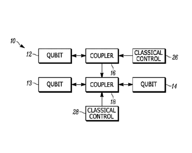
[0007] FIG. 1 illustrates one example of a system comprising three
coupled
superconducting qubits;
[0008] FIG. 2 illustrates one example of quantum circuit employing a ZZZ
coupler
assembly to couple a first qubit, a second qubit, and a third qubit in
accordance with an
aspect of the present invention;
[0009] FIG. 3 is a chart illustrating, for the circuit of FIG. 2, a
strength of a ZZ
coupling between the second and third qubits provided by the second tunable
coupler,
represented in gigahertz, as a function of the flux applied to the tuning
circuit,
represented in thousandths of the flux quantum (m00);
[0010] FIG. 4 is a chart illustrating, for the circuit of FIG. 2, a
strength of a ZZZ
coupling among the first, second, and third qubits provided by the coupler
assembly,
represented in gigahertz, as a function of the first applied flux and the
second applied
flux, represented in thousandths of the flux quantum (m00);
3
Date Recue/Date Received 2021-11-23
[0011] FIG. 5 illustrates one example of quantum circuit comprising three
qubits
coupled via a galvanic coupler assembly that allows for arbitrary ZZZ and
pairwise ZZ
couplings; and
[0012] FIG. 6 illustrates one method for providing a ZZZ coupling among
three
qubits.
DETAILED DESCRIPTION
[0013] The ZZZ coupler described herein is intended for use in a quantum
computing environment, in which information is stored and manipulated in
superconducting qubits. A physical implementation of a qubit can be a
Josephson
junction, a quantum dot, a SQUID (superconducting quantum interference
device), a
Cooper pair box, or an ion trap. Further, unless specified, the coupling of
two elements
may be accomplished according to the invention using any of various means of
physical
coupling, for example, a mechanical coupling by means of an electrical
conductor,
capacitive coupling, inductive coupling, magnetic coupling, nuclear coupling,
and optical
coupling, or any combination of the foregoing. As used herein, a "classical
control"
indicates a device that behaves generally according to the laws of classical
physics that
provides a control signal to a quantum element, such as a qubit or coupler.
[0014] The systems and methods herein provide arbitrary coupling among
three
superconducting qubits, as well as any pair of the three qubits, along a Z-
basis. A ZZ
coupling between two qubits makes it energetically favorable for the states of
the first
and second qubits to assume a specific relationship with respect to the Z-axis
of the
Bloch sphere, both pointing either in the +Z direction or both in the ¨Z
direction.
Similarly, a ZZZ coupling among three qubits makes it energetically favorable
for the
states of all three qubits to align in the same direction along the Z-axis,
all pointing
either in the +Z direction or all pointing in the ¨Z direction. Each axis
corresponds to a
specific quantum state defined on the Bloch sphere of the qubit. It will be
appreciated
that the coupling can be positive or negative, with a negative ZZ coupling
making it
energetically favorable for the states of the first and second qubits to align
in the same
4
Date Recue/Date Received 2021-11-23
direction along the Z-axis, both pointing either in the +Z direction or both
in the ¨Z
direction. A positive ZZ coupling, denoted as +ZZ, making it energetically
favorable for
the states of the first and second qubits to align in different directions
along the Z-axis.
[0015] Most particle interactions found in nature are two body in
character. When
three body terms exist, they tend to be weak in comparison to two body
interactions.
This disclosure describes a device that solves both of these challenges
generating a
strong, tunable, three body ZZZ interactions between flux qubits, as well as
independently tunable two body ZZ interactions, including the case where two
body
interactions are zero. Specifically, the inventors have designed a circuit
utilizing a novel
coupling method that generates a three qubit interaction by modulating the
strength of a
qubit-qubit interaction based on the state of a third qubit. In one
implementation,
compatible with high coherence flux qubits, the circuit utilizes an inventive
galvanic
Josephson coupling between qubits where Josephson junctions provide the mutual
inductance.
[0016] FIG. 1 illustrates one example of a system 10 comprising three
coupled
superconducting qubits 12-14. The system includes a first coupler 16 that
couples a
first qubit 12 to a second coupler 18, such that a flux produced by the first
qubit is
directed into a tuning loop of the second coupler. The first coupler 16 can be
selected
to be tunable, such a coupling strength and sign (e.g., positive or negative)
can be
tuned via a control signal provided by a first classical control 26. It will
be appreciated
that the control signal can be selected such that the coupling strength of the
first
coupler 16 is zero, and thus no flux from the first qubit is directed to the
second
coupler 18. In one implementation, the first coupler 16 is a split junction
tunable
coupler, and the interaction strength between qubits is controlled by an
amount of
tuning flux, provided by the first classical control 26, that threads the
tunable junction.
[0017] The second coupler 18 couples the second qubit 13 to the third
qubit 14.
Like the first coupler 16, the second coupler 18 can be selected to be
tunable, such that
a coupling strength and sign can be tuned via a control signal provided by a
second
classical control 28. Accordingly, when the first coupler 16 is tuned to
provide a
Date Recue/Date Received 2021-11-23
non-zero coupling, a coupling strength of the second coupler 18 is a function
of the
control signal provided by the second classical control 28 and the state of
the first
qubit 12. In one implementation, the second coupler 18 is a split junction
tunable
coupler, and the interaction strength between qubits is controlled by an
amount of
tuning flux, provided by the second classical control 28, that threads the
tunable
junction, as well as an amount of flux from the first qubit 12 directed into
the second
coupler by the first coupler 16.
[0018] In one implementation, the second qubit 13 and the third qubit 14
are
coupled through the second coupler 18, with each qubit coupled to the second
coupler
via a galvanic Josephson mutual inductance. Optimizing the strength of ZZZ
coupling is
important for successful device operation since the energy scale of the
coupling often
needs to be greater than other energies or frequencies in the problem such as
the
energy associated with the achievable base temperature of the experiment.
Further, it
is helpful for the coupler to be compatible with highly coherent flux qubits
which typically
utilize junctions with small critical current to minimize dephasing from flux
noise. The
high coherence facilitates quantum effects. The small critical current limit
places
important restrictions on inductive elements that are part of qubit-qubit
tunable couplers.
These constraints are derived from the relationship between junction critical
current,
and the effective Josephson inductance of a junction Lj = (1)0/27r/c, where
(1)0/27r-330 nA nH.
[0019] For instance, for an /c-50 nA junction, the Josephson inductance
is
¨6.6 nH. To generate a strong coupling via inductive coupling, the mutual
inductance
between coupled qubits should be a significant fraction of this value. Often
mutual
inductances, including all geometric mutuals, are generated with linear
inductances. To
understand the challenges involved with generating such a large inductance
with linear
inductors, consider that to generate an L1-6.6 nH inductance with a Z = 50 Ohm
metal
trace and propagation speed v--c/3, where c is the speed of light in a vacuum,
requires
a trace length Ljv/Z which is longer than one centimeter. This presents a
technical
challenge since geometric couplers would need to be quite large relative to
the rest of
6
Date Recue/Date Received 2021-11-23
the circuit, and stray capacitance could limit achievable inductance at
relevant
frequencies. The inventors have found that the use of galvanic coupling
overcomes
many of these challenges.
[0020] FIG. 2 illustrates one example of quantum circuit 50 employing a
ZZZ
coupler assembly 60 to couple a first qubit 72, a second qubit 74, and a third
qubit 76 in
accordance with an aspect of the present invention. The coupler assembly 60
includes
a first tunable coupler 62, including a first tuning loop 66, and a second
tunable
coupler 64, including a second tuning loop 68. In the illustrated
implementation, each of
the first and second tuning loops 66 and 68 are compound Josephson junctions,
formed
as superconducting loops interrupted by two Josephson junctions. The first
tunable
coupler 62 directs flux from the first qubit 72 into the second tunable
coupler 64. The
second tunable coupler 64 couples the second qubit 74 to the third qubit 76 in
the Z
basis, with each qubit 74 and 76 coupled to the second tunable coupler via a
galvanic
Josephson mutual inductance. Accordingly, when a coupling strength of the
second
tunable coupler is non-zero, it is energetically favorable for the states of
the first and
second qubits to assume a specific relationship with respect to the Z-axis. In
the
illustrated implementation, the flux from the first qubit 72 is provided
inductively through
at least one pair of inductive elements 69 bridging the first tunable coupler
62 and the
tuning loop 68 of the second tunable coupler 64.
[0021] In the illustrated implementation, each of the first qubit 72, the
second
qubit 74, and the third qubit 76 are implemented as four junction flux qubits,
with first
and second junctions of each qubit 72, 74, and 76 forming a compound junction
82, 84,
and 86 for biasing the flux qubits. A third and fourth junction 91-94 complete
the flux
qubit loops, with junctions 92 and 94 forming the galvanic Josephson mutual
inductance
shared by qubits 74 and 76, respectively, with the tunable coupler 68. A flux
qubit, in
general terms, is a superconducting loop interrupted by some number of
Josephson
junctions. While a biasing element is not illustrated in the simplified
example of FIG. 2,
in general operation, a flux qubit is biased by a flux, generally described in
units of the
superconducting flux quantum (1),3. When the applied bias flux in loops 82,
84, or 86 is
7
Date Recue/Date Received 2021-11-23
near one flux quantum and for suitable device parameters, the potential energy
of the
system exhibits two minima, one corresponding to clockwise and the other to
counterclockwise current flow in the superconducting loop. The two possible
directions
of current flow represent the lowest energy quantum states of the system.
While it is
also possible to have a single potential well even at a flux quantum of bias
flux, the
double-well regime described here highlights the unique capability of the
inventive
coupler to function even with energetically degenerate states. It will be
appreciated that
the coupling assembly 60 can also be used for generating three body inductive
coupling
between Transmon qubits. In this case the strength of three body interaction
term is
reduced due to the lower RMS current compared to the static currents in the
flux
regime.
[0022] The inductive potential of the full circuit can be modelled, with
suitable
generalization for mutual inductances, using ¨(1)0/c/2ff cos 0 for each
junction and
(1/2L)((1)0/270202 for each inductor, where 0 is the gauge invariant phase
across the
circuit element. When the flux qubits are tuned to the harmonic oscillator, or
single well,
regime, the potential shows a single minimum. When the flux qubits are tuned
to the
flux, or double well, regime, and all the couplings are off, the potential
shows eight
degenerate minimums corresponding to the eight qubit states. The energy of
each
minimum can be given a label 'Jab, where, a represents a state of the first
qubit 72, b
represents a state of the second qubit 74, and c represents a state of the
third qubit 76,
such that U010 is the minimum energy of the well corresponding to the qubit
state 010.
Tuning either coupler 62 or 64, to a non-zero coupling strength adjusts the
energy of
each minimum. For a Hamiltonian of the form H/h= ¨g123ZZZ the value of 9123,
determines the ZZZ coupling energy. Here, h is Plank's constant, which relates
coupling
energies and coupling frequencies. When the qubits are in the flux regime the
value of
9123 can be calculated as 7abc - z(a)z(b)z(c)Uabc/8 where z(0) = 1 and z(1) =
¨1. The
A_J
ZZ energy between the second qubit 74 and the third qubit 76 can be calculated
as
Eabc z(b)z(c)Uabc18. This method accurately determines the energy scales of
the
lowest eigenstates of the corresponding quantum Hamiltonian as long the
control fluxes
8
Date Recue/Date Received 2021-11-23
stay within an MRT (macroscopic resonant tunneling) spacing, that is, as long
as the
difference in energy between potential wells stays below the local harmonic
energy of
each well. This depends on the qubit's shunt capacitance in addition to the
inductive
potential.
[0023] By utilizing compound Josephson junction coupling techniques, the
coupler assembly 60 does not bias individual qubits, that is, no single qubit
Z terms are
generated in the Hamiltonian of the system by the assembly. This invention can
be
configured to utilize multiple operating points by altering a first applied
flux, (1)1, provided
to the first tuning loop 66, and a second applied flux, (1)2, provided to the
second tuning
loop 68. These fluxes can be adjusted to separately control the ZZ coupling
provided
by the second tunable coupler 64 as well as the ZZZ coupling provided by the
assembly 60 through the first tunable coupler 62. For example, the fluxes can
be
provided such that both the ZZ and ZZZ couplings are inactive. In this
instance,
example values for the two applied fluxes could include ()1, (1)2) =
(0.5,0.5)(I)o. To
activate the ZZ coupling, with an arbitrary sign, without the ZZZ coupling,
values of
((I)1, (1)2) = (0.5,0.5 + 0.5)(1)0 could be used. It will be appreciated that
the value of the
second applied flux will vary across the range given depending on a desired
strength
and sign of the coupling. When the flux is provided to avoid the ZZZ coupling,
a
Hamiltonian of the system would not include a ZZZ term. To activate the ZZZ
coupling,
with an arbitrary sign, without the ZZ coupling, the applied flux values could
include
()1, (1)2) = (0, +0.5)(I)o. In this case, a Hamiltonian of the system would
not contain a
term representing the ZZ coupling between the second qubit 74 and the third
qubit 76,
although it would contain a term representing the ZZZ coupling. Finally, to
provide ZZ
coupling and ZZZ coupling, values including (4)1,02) = (0, +0.5 + 0.2)(1)0 can
be used.
[0024] FIG. 3 is a chart 100 illustrating, for the circuit of FIG. 2, a
strength of a ZZ
coupling between the second and third qubits 74 and 76 provided by the second
tunable
coupler 64, represented in gigahertz, as a function of the flux applied to the
tuning
circuit 68, represented in thousandths of the flux quantum (ffic1)0). In this
example, it is
assumed that the Josephson junctions in the compound junctions 82, 84, and 86
of the
9
Date Recue/Date Received 2021-11-23
flux qubits 72, 74, and 76 have critical currents of thirty-five nanoamps, the
other
Josephson junctions in the qubits have critical currents of seventy nanoamps,
and the
junctions in the two couplers 62 and 64 have critical currents of twenty-five
nanoamps.
The inductive elements 62 each have an inductance of one hundred and fifty
picohenry,
with the efficiency of the mutual inductance being 0.5. The coupling strength
is
represented on the vertical axis 102, while the applied flux is represented on
the
horizontal axis 104. As can be seen from the chart 100, the coupling strength
is at a
minimum when the applied flux is near (1000*n+500)mc1)0, where n is an
integer. A
maximum positive coupling is achieved when the applied flux is near 2000n m00,
and a
maximum negative coupling is achieved when the applied flux is near
(2000n+1000)
m00. Values between these extremes can be selected to tune the coupling
strength to
a desired magnitude and sign. One of ordinary skill in the art will recognize
that
fabrication variation of the critical currents will slightly alter the flux
values where zero
couplings occur.
[0025] FIG. 4 is a chart 150 illustrating, for the circuit of FIG. 2, a
strength of a
ZZZ coupling among the first, second, and third qubits 72, 74, and 76 provided
by the
coupler assembly 60, represented in gigahertz, as a function of the first
applied flux and
the second applied flux, represented in thousandths of the flux quantum
(rn00). In this
chart, the parameters for the circuit, such as the bias to the qubits 72, 74,
and 76 and
the critical currents of the various Josephson junctions, are selected such
that the ZZ
coupling energy is independent of the first applied flux. As with FIG. 3, it
is assumed in
this example that the Josephson junctions in the compound junctions 82, 84,
and 86 of
the flux qubits 72, 74, and 76 have critical currents of thirty-five nanoamps,
the other
Josephson junctions in the qubits have critical currents of seventy nanoamps,
and the
junctions in the two couplers 62 and 64 have critical currents of twenty-five
nanoamps.
The inductive elements 62 each have an inductance of one hundred and fifty
picohenry,
with the efficiency of the mutual inductance being 0.5. The coupling strength
is
Date Recue/Date Received 2021-11-23
represented on the vertical axis 152, while the second applied flux is
represented on the
horizontal axis 154.
[0026] The value of the first applied flux is represented by the
individual
plots 161-171, with each plot representing the ZZZ coupling strength for a
different
value of the first applied flux. A first plot 161 represents the ZZZ coupling
strength when
the first applied flux is zero. A second plot 162 represents the ZZZ coupling
strength
when the first applied flux is equal to one-tenth of the flux quantum. A third
plot 163
represents the ZZZ coupling strength when the first applied flux is equal to
one-fifth of
the flux quantum. A fourth plot 164 represents the ZZZ coupling strength when
the first
applied flux is equal to three-tenths of the flux quantum. A fifth plot 165
represents the
ZZZ coupling strength when the first applied flux is equal to two-fifths of
the flux
quantum. A sixth plot 166 represents the ZZZ coupling strength when the first
applied
flux is equal to one-half of the flux quantum. As can be seen from the chart
150, when
the first applied flux is equal to one-half of the flux quantum, no ZZZ
coupling is present,
regardless of the value of the second applied flux. Further, it will be
appreciated that
the magnitude and sign of the ZZZ coupling can be selected by tuning the
values for the
first and second applied flux.
[0027] A seventh plot 167 represents the ZZZ coupling strength when the
first
applied flux is equal to three-fifths of the flux quantum. An eighth plot 168
represents
the ZZZ coupling strength when the first applied flux is equal to seven-tenths
of the flux
quantum. A ninth plot 169 represents the ZZZ coupling strength when the first
applied
flux is equal to four-fifths of the flux quantum. A tenth plot 170 represents
the ZZZ
coupling strength when the first applied flux is equal to nine-tenths of the
flux quantum.
An eleventh plot 171 represents the ZZZ coupling strength when the first
applied flux is
equal to the flux quantum. It will be appreciated that this provides a maximum
value for
the ZZZ coupling strength.
[0028] FIG. 5 illustrates one example of quantum circuit 200 comprising
three
qubits 202, 204, and 206 coupled via a galvanic coupler assembly 210 that
allows for
arbitrary pairwise couplings. Compared to the circuit of FIG. 2, the
illustrated circuit 200
11
Date Recue/Date Received 2021-11-23
increases the ZZZ coupling energy by a factor of three and symmetrizes the
design for
robustness. In the circuit, the first qubit 202 and the second qubit 204 are
coupled via a
galvanic Josephson mutual inductance through a first tunable coupler 212, the
second
qubit and the third qubit 206 are coupled via a galvanic Josephson mutual
inductance
through a second tunable coupler 214, and the first qubit and the third qubit
are coupled
via a galvanic Josephson mutual inductance through a third tunable coupler
216. For
the purpose of this example, each of the first tunable coupler 212, the second
tunable
coupler 214, and the third tunable coupler 216 can be assumed to be
substantially
equivalent in structure and function to the second tunable coupler 64 of FIG.
2.
[0029] Each of the first, second, and third qubits 202, 204, and 206 are
also
coupled, respectively, to the second tunable coupler 212, the third tunable
coupler 216,
and the first tunable coupler 212 such that flux from the qubits is directed
into a tuning
loop of their respective coupler to facilitate the ZZZ interactions among the
qubits.
Specifically, the first qubit 202 is coupled to the second tunable coupler 214
through a
fourth tunable coupler 222, the second qubit 204 is coupled to the third
tunable
coupler 216 through a fifth tunable coupler 224, and the third qubit 206 is
coupled to the
first tunable coupler 212 through the sixth tunable coupler 226. For the
purpose of this
example, each of the fourth tunable coupler 222, the fifth tunable coupler
224, and the
sixth tunable coupler 226 can be assumed to be substantially equivalent in
structure
and function to the first tunable coupler 62 of FIG. 2.
[0030] The illustrated galvanic coupler 210 allows high coherence, low
critical
current flux qubits to be coupled with a ZZZ coupling strength that can be ten
times
larger than the energy scale set by the base temperature of commercial
dilution
refrigerators, which is currently ¨10 kB mK, where kB is Boltzmann's constant,
even with
ZZ coupling strength tuned to zero. ZZZ couplings are helpful for natively
generating
exculsive or Boolean satisfiability (XOR-3SAT) problem Ham iltonians for
quantum
annealers, for generating coupling Ham iltonians for primitive controlled-
controlled-phase
gates, implementing Hamiltonian operators needed for building encoded qubits
from
physical qubits, and implementing logical operations on distance three encoded
qubits.
12
Date Recue/Date Received 2021-11-23
These couplings need to be large compared to the device temperature in
annealing and
encoding applications, and larger than -h/GateTime for gate or logical
applications
where the operations need to occur in GateTime or faster, where h is Plank's
constant.
To take advantage of quantum effects the coupling scheme needs to be
compatible with
high coherence, low critical current flux qubits.
[0031] The coupler of the present invention can generate arbitrary two
and three
body terms, allowing the circuit to encode the more general three
satisfiability problem
(3SAT) problems. 3SAT is the canonical NP-complete constraint satisfaction
problem.
To see that the circuit 200 is sufficient to natively encode local 3SAT
instances,
consider first a single three bit clause function f (a, b, c) that takes the
value 1 when the
clause is true and 0 when the clause is false. If one now considers a set of
clause
functions {fi} that comprise a MAX3SAT instance, then finding the variables
that
maximizes the number of satisfied clauses is equivalent to minimizing the cost
function
- Ei fi. Now consider the three qubit operator F
A_Jabc f (a, b, c)labc)(abc I derived from
the clause function f. Since the operator is diagonal in the Z-basis it can be
decomposed as F = g0111 + g1Z11 + g21Z1 + g311Z + g12ZZ1 + g13Z1Z + g231ZZ +
g123ZZZ, where Z is the Pauli Z operator and / the identity. After including
necessary
controls for single qubit bias fields, the circuit 200 can simultaneously
generate all
required couplings to implement the cost function operator -L Fi and thus can
natively
encode the local 3SAT instance. Finding the global minimum of the cost
function not
only solves the associated satifiability problem, but the more general problem
of finding
the maximum number of satisfiable clauses (MA)(-SAT). The locality constraint
reduces
the number 3SAT instances that can be natively solved using the present
invention,
however, MAX-XOR-3SAT remains NP-hard even when restricted to local
(bounded-degree) planer hypergraphs. Given sufficient precision of the bias
fields, the
circuit can natively encode more general weighted MAX-3SAT constraint
satisfaction
problems.
[0032] In view of the foregoing structural and functional features
described above
in FIGS. 1-5, an example method will be better appreciated with reference to
FIG. 6.
13
Date Recue/Date Received 2021-11-23
While, for purposes of simplicity of explanation, the method of FIG. 6 is
shown and
described as executing serially, it is to be understood and appreciated that
the present
invention is not limited by the illustrated order, as some actions could in
other examples
occur in different orders and/or concurrently from that shown and described
herein.
[0033] FIG. 6 illustrates one method 250 for providing a ZZZ coupling
among
three qubits. At 252, a first qubit of the three qubits is coupled to a second
qubit of the
three qubits via a first tunable coupler utilizing galvanic Josephson mutual
inductance.
It will be appreciated that the first tunable coupler can share one or more
Josephson
junctions with the first and second qubits to facilitate the galvanic
coupling. At 254, the
second qubit is coupled to a third qubit of the three qubits via a second
tunable coupler
utilizing galvanic Josephson mutual inductance. At 256, the third qubit is
coupled to the
first qubit via a third tunable coupler utilizing galvanic Josephson mutual
inductance.
[0034] At 258, the first qubit is coupled to the second tunable coupler
via a fourth
tunable coupler such that a flux from the first qubit is directed into a
tuning loop of the
second tunable coupler. Accordingly, a state of the first qubit can influence
the coupling
strength of the second tunable coupler. At 260, the second qubit is coupled to
the third
tunable coupler via a fifth tunable coupler such that a flux from the second
qubit is
directed into a tuning loop of the third tunable coupler. At 262, the third
qubit is coupled
to the first tunable coupler via a sixth tunable coupler such that a flux from
the third qubit
is directed into a tuning loop of the first tunable coupler. The resulting
circuit allows for
ZZZ coupling among the circuits having a sign and coupling strength tunable
via control
signals provided to the tunable couplers, as well as arbitrary ZZ couplings
among the
three qubits.
[0035] What have been described above are examples of the present
invention.
It is, of course, not possible to describe every conceivable combination of
components
or methodologies for purposes of describing the present invention, but one of
ordinary
skill in the art will recognize that many further combinations and
permutations of the
present invention are possible. Accordingly, the present invention is intended
to
14
Date Recue/Date Received 2021-11-23
embrace all such alterations, modifications, and variations that fall within
the scope of
the appended claims.
Date Recue/Date Received 2021-11-23