Note: Descriptions are shown in the official language in which they were submitted.
ARTICLES COMPRISING ADDITIVELY-MANUFACTURED COMPONENTS AND
METHODS OF ADDITIVE MANUFACTURING
CROSS-REFERENCE TO RELATED APPLICATIONS
This application claims the benefit of United States Provisional Patent
Application No.
62/851,080 filed May 21, 2019, United States Provisional Patent Application
No.
62/850,831 filed May 21, 2019, United States Provisional Patent Application
No.
62/881,687 filed August 1,2019, United States Provisional Patent Application
No.
62/910,002 filed October 3,2019 and United States Provisional Patent
Application No.
62/969,307 filed February 3, 2020.
FIELD
This disclosure generally relates to articles, such as of athletic gear (e.g.,
helmets,
shoulder pads or other protective equipment, hockey sticks or other sporting
implements, etc.) and other equipment, and, more particularly, to articles
including
components made by additive manufacturing.
BACKGROUND
Articles, such as devices or other functional items, are manufactured for
various
purposes.
For example, articles of athletic gear are made for users engaging in sports
or other
athletic activities. Helmets, for example, are worn in sports and other
activities (e.g.,
motorcycling, industrial work, military activities, etc.) to protect their
wearers against
head injuries. To that end, helmets typically comprise a rigid outer shell and
inner
padding to absorb energy when impacted.
1
Date Recue/Date Received 2023-05-01
CA 03140505 2021-11-15
WO 2020/232555
PCT/CA2020/050689
Helmets are often desired to be lightweight and have various properties, such
as
strength, impact resistance, linear and rotational impact protection,
breathability,
compactness, comfort, etc., which can sometimes be conflicting, require
tradeoffs, or
not be readily feasible, for cost, material limitations, manufacturability,
and/or other
reasons.
Manufacturing of various devices often involves molding parts of these
devices, such as
by injection molding, compression molding, thermoforming, etc. For example,
athletic
gear such as helmets, shoulder pads, sporting implements (e.g., hockey
sticks), etc.,
typically comprise molded parts.
More recently, additive manufacturing techniques have been used to manufacture
various devices. Additive manufacturing usually entails building up layers of
feedstock
materials layer-by-layer to substantially final dimensions of the parts. In
some cases,
this may present certain drawbacks. For example, the final dimensions of the
parts may
is generally constrained by the maximum dimensions over which the additive
material
can be distributed in the layer-building process. As another example,
additively
manufacturing larger parts may take longer to manufacture because the additive
material must be distributed over a larger area/volume. As yet another
example,
characteristics of additively-manufactured parts are often dictated or
affected by their
additive-manufacturing process.
For these and other reasons, there is a need to improve manufacturability,
performance
and use of devices and articles comprising additively-manufactured parts.
SUMMARY
According to various aspects, this disclosure relates to a component for an
article, the
component comprising a 3D-printed portion, the component including expandable
material expanded to define the component.
2
CA 03140505 2021-11-15
WO 2020/232555
PCT/CA2020/050689
According to another aspect, this disclosure relates to an article comprising
a
component according to the above aspect.
According to another aspect, this disclosure relates to a component for an
article, the
component comprising a 3D-printed portion, the component including expandable
material expanded from an initial shape to an expanded shape that is a scaled-
up
version of the initial shape.
According to another aspect, this disclosure relates to a method of making a
component
of an article, the method comprising: providing expandable material; 3D
printing a 3D-
printed portion of the component; and expanding the expandable material to
define the
component.
According to another aspect, this disclosure relates to an article comprising
a
component made by the method according to the above aspect.
According to another aspect, this disclosure relates to a component for an
article, the
component comprising 3D-printed expandable material expanded after being 3D
printed.
According to another aspect, this disclosure relates to an article comprising
a
component according to the above aspect.
According to another aspect, this disclosure relates to a method of making a
component
of an article, the method comprising: providing expandable material; 3D
printing the
expandable material to create 3D-printed expandable material; and expanding
the 3D-
printed expandable material to define the component.
According to another aspect, this disclosure relates to an article comprising
a
component made by the method according to the above aspect.
3
CA 03140505 2021-11-15
WO 2020/232555
PCT/CA2020/050689
According to another aspect, this disclosure relates to an impact absorbing
article
comprising an additively-manufactured component; a first portion of the
additively-
manufactured component is configured to protect more against higher-energy
impacts
than lower-energy impacts; and a second part of the additively-manufactured
component is configured to protect more against lower-energy impacts than
higher-
energy impacts.
According to another aspect, this disclosure relates to an article comprising
a plurality of
additively-manufactured components with different functions additively-
manufactured
integrally with one another.
According to another aspect, this disclosure relates to an article comprising
an
additively-manufactured component and a non-additively-manufactured component
received by the additively-manufactured component.
According to another aspect, this disclosure relates to an article comprising
an
additively-manufactured component and a sensor associated with the additively-
manufactured component.
According to another aspect, this disclosure relates to a method of making an
impact
absorbing article, the method comprising: providing feedstock; and additively
manufacturing a component of the impact absorbing article using the feedstock,
wherein: a first part of the additively-manufactured component is configured
to protect
more against higher-energy impacts than lower-energy impacts; and a second
part of
the additively-manufactured component is configured to protect more against
lower-
energy impacts than higher-energy impacts.
According to another aspect, this disclosure relates to a method of making an
impact
absorbing article, the method comprising: providing feedstock; and additively
manufacturing a plurality of components of the impact absorbing article that
have
different functions integrally with one another, using the feedstock.
4
CA 03140505 2021-11-15
WO 2020/232555
PCT/CA2020/050689
BRIEF DESCRIPTION OF DRAWINGS
A detailed description of embodiments is provided below, by way of example
only, with
reference to drawings accompanying this description, in which:
Figure 1 shows an embodiment of an article comprising additively-manufactured
components, in which the article is an article of athletic gear, and more
particularly a
helmet for protecting a user's head;
Figure 2 shows a front view of the helmet;
Figures 3 and 4 show rear perspective views of the helmet;
Figures 5 and 6 show examples of a faceguard that may be provided on the
helmet;
Figures 7 and 8 show the head of a user;
Figure 9 shows internal dimensions of a head-receiving cavity of the helmet;
Figures 10 to 13 show operation of an example of an adjustment mechanism of
the
helmet;
Figures 14 and 15 show an example of shell members of an outer shell of the
helmet;
Figures 16 to 20 show an example of a plurality of additively-manufactured
components
constituting a plurality of pads of an inner liner of the helmet;
Figures 21A to 21C show examples of linear acceleration at a center of gravity
of a
headform caused by a linear impact on a helmet at three energy levels
according to
hockey STAR methodology;
5
CA 03140505 2021-11-15
WO 2020/232555
PCT/CA2020/050689
Figures 22A and 22B show examples of stress-strain curves for additively
manufactured
components comprising a pad of an inner liner of a helmet;
Figure 23 shows an example of an additively-manufactured lattice structure
that may be
used in an additively-manufactured component;
Figure 24A shows an example of a unit cell occupying a voxel that may be used
to form
an additively-manufactured component;
Figure 24B shows another example of a mesh or shell style unit cell that may
be used to
form an additively-manufactured component;
Figures 24C, 24D, 24E and 24F shows further examples of unit cells that may be
used
to form an additively-manufactured component;
Figures 25A, 25B, 25C, 25D, 25E, 25F and 25G show examples how a volume
occupied by an additively-manufactured component may be populated with
different
combinations of unit cells;
Figure 26 shows examples of lattice and non-lattice "skins" that may be formed
on a
lattice structure in order to provide an outer surface for the lattice
structure;
Figure 27 shows a side view of an example of an additively-manufactured
component
constituting a front pad member of the inner lining of the helmet;
Figures 28A and 28B show an example of an additively-manufactured component
comprising a two-dimensional (2D) lattice structure;
Figure 29 shows an example of an additively-manufactured component comprising
a
.. three-dimensional (3D) lattice structure;
6
CA 03140505 2021-11-15
WO 2020/232555
PCT/CA2020/050689
Figures 30A, 30B and 30C show another example of an additively-manufactured
component comprising a 3D lattice structure;
Figure 31 shows yet another example of an additively-manufactured component
comprising a 3D lattice structure;
Figure 32 shows still another example of an additively-manufactured component
comprising a 3D lattice structure;
Figure 33 shows an example of an additively-manufactured component
constituting a
shoulder cap member of shoulder padding for a hockey or lacrosse player;
Figures 34A, 34B and 34C show an example of an additively-manufactured
component
constituting an occipital pad member of the inner lining of a hockey helmet;
Figures 35A, 35B, 35C and 35D show examples of additively-manufactured
components comprising a plurality of distinct zones structurally different
from one
another;
Figure 36 shows examples of additively-manufactured components comprising
lattice
structures utilizing the same unit cell but different voxel sizes;
Figures 37A and 37B show another example of an additively-manufactured
component
constituting an occipital pad member of the inner lining of a hockey helmet;
Figure 38 shows examples of additively-manufactured components comprising
lattice
structures utilizing the same unit cell but different elongated member sizes;
Figures 39A and 39B show an example of pads of a helmet in an open position
and a
closed position, respectively;
7
CA 03140505 2021-11-15
WO 2020/232555
PCT/CA2020/050689
Figure 40 shows an example of a precursor of a post-molded expandable
component
being expanded to form the post-molded expandable component;
Figure 41 is a block diagram representing an example of an expandable material
of the
post-molded expandable component;
Figure 42 shows an example of an expansion agent of the expandable material of
the
post-molded expandable component;
Figure 43 shows a cross-sectional view of a sport helmet with inner padding
that
includes additively-manufactured components integrated into post-molded
expandable
components;
Figure 44 shows an example of a precursor of a post-additively manufactured
expandable component being expanded to form the post-additively manufactured
expandable component;
Figure 45 shows a schematic of an example of a binder jetting system for
forming a
precursor of a post-additively-manufactured expandable component;
Figure 46 shows an exploded view of an example of inner padding for a sport
helmet in
which the comfort pads include additively manufactured components;
Figure 47 shows a cross-sectional view of a portion of the inner padding of
Figure 46;
Figures 48A and 48B show examples of a liquid crystal elastomer material in
compressed and uncompressed states;
Figure 49 shows an example of inner padding for a sport helmet that includes
liquid
crystal elastomer components;
8
CA 03140505 2021-11-15
WO 2020/232555
PCT/CA2020/050689
Figure 50 shows an example of an additively manufactured component with a
lattice
structure in which liquid crystal elastomer components have been incorporated;
Figure 51 shows a cross-sectional view of a sport helmet with inner padding
that
includes air channels integrally formed within additively manufactured
components of
the inner padding;
Figure 52 shows an example of additively-manufactured components constituting
a chin
cup and a face mask of a helmet;
Figures 53A, 538 and 53C show an example of an additively-manufactured
component
constituting a face mask of a helmet for a hockey goalie;
Figure 54 shows an embodiment of a lacrosse helmet comprising additively-
manufactured components;
Figure 55 shows an embodiment of a sporting implement that is a hockey stick;
Figure 56 is a top view of a bottom portion of a shaft of the hockey stick and
a blade of
the hockey stick;
Figure 57 is a rear view of the bottom portion of the shaft of the hockey
stick and the
blade of the hockey stick;
Figure 58 is an embodiment of a lattice comprised in the hockey stick;
Figure 59 is a variant of the hockey stick;
Figure 60 is a portion of the shaft of the hockey stick;
Figures 61 to 65 show examples of framework of the lattice;
9
CA 03140505 2021-11-15
WO 2020/232555
PCT/CA2020/050689
Figures 66 and 67 show elongate members of the lattice forming a node in
accordance
with an embodiment;
Figures 68 and 69 show the elongate members of the lattice forming the node in
accordance with another embodiment;
Figures 70 to 75 show cross-sectional shapes of the elongate members of the
lattice in
accordance with various embodiments;
Figures 76 to 81 show cross-sectional structures of the elongate members of
the lattice
in accordance with various embodiments;
Figure 82 shows a cross-section of a truss the lattice at the shaft of the
hockey stick;
Figures 83 to 87 show variants of the cross-section of a truss the lattice at
the shaft of
the hockey stick;
Figures 88 to 91 show a cross-section of the shaft of the hockey stick in
accordance
with various embodiments;
Figures 92 and 93 show cross-sections of the blade of the hockey stick;
Figure 94 shows an intersection between two zones of the lattice having
different voxel
sizes;
Figure 95 shows an intersection between two zones of the lattice having
elongate
members and/or nodes of different thicknesses (or different "struts size");
Figures 96A to 96H shows a manufacturing of the lattice in accordance with an
embodiment;
CA 03140505 2021-11-15
WO 2020/232555
PCT/CA2020/050689
Figure 97 shows a variant of the lattice;
Figure 98 to 109 show variants of the hockey stick;
Figure 110 shows another embodiment wherein the sporting implement is a goalie
stick;
Figure 111 shows another embodiment wherein the sporting implement is a
lacrosse
stick;
Figure 112 shows another embodiment wherein the sporting implement is a ball
bat;
Figure 113 shows an example of a test for determining the strength of the
sporting
implement;
Figure 114 shows an embodiment of footwear in which the footwear is a skate
for a user
comprising a skate boot and a blade holder and comprising additively-
manufactured
components;
Figure 115 shows an exploded view of the skate;
Figures 116 and 117 are side and front views of a right foot of the skater
with an
integument of the foot shown in dotted lines and bones shown in solid lines;
Figures 118 to 126 show cross-sectional views of a shell of the skate boot in
accordance with various embodiments;
Figure 127 shows a tendon guard of the skate boot;
Figure 128 to 134 show perspective views, a lateral side view, a top view, a
bottom
view, a front view and a rear view of the blade holder;
11
CA 03140505 2021-11-15
WO 2020/232555
PCT/CA2020/050689
Figures 135A and 1358 show a lateral side view and a cross-sectional view of a
blade
in accordance with an embodiment;
Figures 136A and 1368 show a variant of the blade;
Figures 137 to 139 show an assembly of the blade and the blade holder
comprising a
blade detachment mechanism;
Figures 140 to 141 show variants of the assembly of the blade and the blade
holder and
of the blade detachment mechanism;
Figures 144 to 148 show variants of the skate;
Figures 149 to 159 show a variant of the blade detachment mechanism;
Figures 160 to 163 show another variant of the blade detachment mechanism;
Figure 164 shows a variant of the blade wherein the blade comprises a
silkscreen;
Figures 165 to 167 show a variant of the skate wherein the additively-
manufactured
components comprise sensors and actuators;
Figures 168 to 170 show variants of the skate;
Figure 171 shows a variant of the skate wherein the skate comprises a
covering;
Figure 172 to 176 show examples of variants in which the footwear is a ski
boot, a work
boot, a snowboard boot, a sport cleat or a hunting boot;
12
CA 03140505 2021-11-15
WO 2020/232555
PCT/CA2020/050689
Figure 177 is another example of footwear wearable by the user and comprising
an
additively manufactured component in accordance with another embodiment, in
which
the footwear is a running shoe; and
Figure 178 show an example of a footbed comprising an additively manufactured
component in accordance with another embodiment
Figure 179 show an embodiment in which an additively manufactured component is
comprised by an arm guard;
Figure 180 shows an embodiment in which an additively manufactured component
is
comprised by shoulder pads;
Figure 181 shows an embodiment in which an additively manufactured component
is
comprised by a leg guard;
Figure 182 shows an embodiment in which an additively manufactured component
is
comprised by a chest protector;
Figure 183 shows an embodiment in which an additively manufactured component
is
comprised by a blocker glove;
Figure 184 shows an embodiment in which an additively manufactured component
is
comprised by a hockey goalkeeper leg pad;
Figure 185 shows an embodiment in which an additively manufactured component
is
comprised by a piece of personal protective equipment;
Figure 186 shows an embodiment in which an additively manufactured component
is
comprised by an automobile seat;
13
CA 03140505 2021-11-15
WO 2020/232555
PCT/CA2020/050689
Figure 187 shows an embodiment in which an additively manufactured component
is
comprised by a child's car seat;
Figure 188 shows an embodiment in which an additively manufactured component
is
comprised by a bumper assembly for an automobile; and
Figure 189 shows a method of manufacturing additively-manufactured components.
It is to be expressly understood that the description and drawings are only
for purposes
of illustrating certain embodiments and are an aid for understanding. They are
not
intended to be and should not be limiting.
DETAILED DESCRIPTION OF EMBODIMENTS
Figures 1 to 4 show an embodiment of an article 10 (e.g., a device or other
functional
article) comprising additively-manufactured components 121-12A. in accordance
with an
embodiment of the present disclosure.
Each of the additively-manufactured components 121-12A of the article 10 is a
part of
the article 10 that is additively manufactured, i.e., made by additive
manufacturing, also
known as 3D printing, in which material 50 thereof initially provided as
feedstock (e.g.,
powder, liquid, filaments, fibers, and/or other suitable feedstock), which can
be referred
to as 3D-printed material 50, is added by a machine (i.e., a 3D printer) that
is computer-
controlled (e.g., using a digital 3D model such as a computer-aided design
(CAD) model
that may have been generated by a 3D scan of the intended wearer's head) to
create it
in its three-dimensional form (e.g., layer by layer, or by continuous liquid
interface
production from a pool of liquid, or by applying continuous fibers, or in any
other way,
normally moldlessly, i.e., without any mold). This is in contrast to
subtractive
manufacturing (e.g., machining) where material is removed and molding where
material
is introduced into a mold's cavity.
14
CA 03140505 2021-11-15
WO 2020/232555
PCT/CA2020/050689
Any 3D-printing technology may be used to make the additively-manufactured
components 121-12A of the article 10. For instance, in some embodiments, one
or more
of the following additive manufacturing technologies may be used individually
or in
combination: material extrusion technologies, such as fused deposition
modeling
(FDM); vat photopolymerization technologies, such as stereolithography (SLA),
digital
light processing (DLP), continuous digital light processing (CDLP) or
continuous liquid
interface production (CLIP) with digital light synthesis (DLS); powder bed
fusion
technologies, such as multi-jet fusion (MJF), selective laser sintering (SLS),
direct metal
laser sintering/selective laser melting (DMLS/SLM), or electron beam melting
(EBM);
.. material jetting technologies, such as material jetting (MJ), nanoparticle
jetting (NPJ) or
drop on demand (DOD); binder jetting (BJ) technologies; sheet lamination
technologies,
such as laminated object manufacturing (LOM); material extrusion technologies,
such
as continuous-fiber 3D printing or fused deposition modeling (FDM), and/or any
other
suitable 3D-printing technology. Non-limiting examples of suitable 3D-printing
technologies may include those available from Carbon (www.carbon3d.com), EOS
(https://www.eos. info/en), HP (https://www8.hp.com/ca/en/printers/3d-
printers. html),
Arevo (https://arevo.com), and Continuous
Composites
(https://wwvv.continuouscomposites.com/).
As further discussed later, in this embodiment, the additively-manufactured
components
121-12A of the article 10, which may be referred to as "AM" components, are
designed
to enhance performance and use of the article 10, such as: impact protection,
including
for managing different types of impacts; fit and comfort; adjustability;
and/or other
aspects of the article 10.
In this embodiment, the article 10 is an article of equipment usable by a
user. More
particularly, in this embodiment, the article 10 is an article of athletic
gear for the user
who is engaging in a sport or other athletic activity. Specifically, in this
embodiment, the
article of athletic gear 10 is an article of protective athletic gear wearable
by the user to
protect him/her. More specifically, in this example, the article of protective
athletic gear
10 is a helmet for protecting a head of the user against impacts. In this
case, the helmet
CA 03140505 2021-11-15
WO 2020/232555
PCT/CA2020/050689
is a hockey helmet for protecting the head of the user, who is a hockey
player,
against impacts (e.g., from a puck or ball, a hockey stick, a board, ice or
another playing
surface, etc., with another player, etc.).
5 .. More particularly, in this embodiment, the helmet 10 comprises an outer
shell 11 and a
liner 15 to protect the player's head. In this example, the helmet 10 also
comprises a
chinstrap 16 for securing the helmet 10 to the player's head. The helmet 10
may also
comprise a faceguard 14 (as shown in Figures 5 and 6) to protect at least part
of the
player's face (e.g., a grid (sometimes referred to as a "cage") and a chin cup
112 as
10 shown in Figure 5 or a visor (sometimes referred to as a "shield") as
shown in Figure 6).
The helmet 10 defines a cavity 13 for receiving the player's head. In response
to an
impact, the helmet 10 absorbs energy from the impact to protect the player's
head. The
helmet 10 protects various regions of the player's head. As shown in Figures 7
and 8,
the player's head comprises a front region FR, a top region TR, left and right
side
regions LS, RS, a back region BR, and an occipital region OR. The front region
FR
includes a forehead and a front top part of the player's head and generally
corresponds
to a frontal bone region of the player's head. The left and right side regions
LS, RS are
approximately located above the player's ears. The back region BR is opposite
the front
region FR and includes a rear upper part of the player's head. The occipital
region OR
substantially corresponds to a region around and under the head's occipital
protuberance.
The helmet 10 comprises an external surface 18 and an internal surface 20 that
contacts the player's head when the helmet 10 is worn. The helmet 10 has a
front-back
axis FBA, a left-right axis LRA, and a vertical axis VA which are respectively
generally
parallel to a dorsoventral axis, a dextrosinistral axis, and a cephalocaudal
axis of the
player when the helmet 10 is worn and which respectively define a front-back
direction,
a lateral direction, and a vertical direction of the helmet 10. Since they are
generally
.. oriented longitudinally and transversally of the helmet 10, the front-back
axis FBA and
the left-right axis LRA can also be referred to as a longitudinal axis and a
transversal
16
CA 03140505 2021-11-15
WO 2020/232555
PCT/CA2020/050689
axis, respectively, while the front-back direction and the lateral direction
can also be
referred to a longitudinal direction and a transversal direction,
respectfully.
The outer shell 11 provides strength and rigidity to the helmet 10. To that
end, the outer
shell 11 typically comprises a rigid material 27. For example, in various
embodiments,
the rigid material 27 of the outer shell 11 may be a thermoplastic material
such as
polyethylene (PE), polyamide (nylon), or polycarbonate, a thermosetting resin,
or any
other suitable material. The outer shell 11 includes an inner surface 17
facing the inner
liner 15 and an outer surface 19 opposite the inner surface 17. The outer
surface 19 of
the outer shell 11 constitutes at least part of the external surface 18 of the
helmet 10. In
some embodiments, the outer shell 11 or at least portions thereof may be
manufactured
via additive manufacturing and portions thereof may have differing properties.
For
example, portions of the outer shell 11 may be additively manufactured such
that they
differ in terms of rigidity (e.g., to save on weight in areas of the helmet in
which rigidity is
less crucial and/or to intentionally provide flexibility in certain areas of
the shell in order
to provide impact cushioning via the shell).
In this embodiment, the outer shell 11 comprises shell members 22, 24 that are
connected to one another. In this example, the shell member 22 comprises a top
portion
21 for facing at least part of the top region TR of the player's head, a front
portion 23 for
facing at least part of the front region FR of the player's head, and left and
right lateral
side portions 25L, 25R extending rearwardly from the front portion 23 for
facing at least
part of the left and right side regions LS, RS of the player's head,
respectively. The shell
member 24 comprises a top portion 29 for facing at least part of the top
region TR of the
player's head, a back portion 31 for facing at least part of the back region
BR of the
player's head, an occipital portion 33 for facing at least part of the
occipital region OR of
the player's head, and left and right lateral side portions 35L, 35R extending
forwardly
from the back portion 31 for facing at least part of the left and right side
regions LS, RS
of the player's head, respectively.
17
CA 03140505 2021-11-15
WO 2020/232555
PCT/CA2020/050689
In this embodiment, the helmet 10 is adjustable to adjust how it fits on the
player's head.
To that end, the helmet 10 comprises an adjustment mechanism 40 for adjusting
a fit of
the helmet 10 on the player's head. The adjustment mechanism 40 may allow the
fit of
the helmet 10 to be adjusted by adjusting one or more internal dimensions of
the cavity
13 of the helmet 10, such as a front-back internal dimension FBD of the cavity
13 in the
front-back direction of the helmet 10 and/or a left-right internal dimension
LRD of the
cavity 13 in the left-right direction of the helmet 10, as shown in Figure 9.
More particularly, in this embodiment, the adjustment mechanism 40 is
configured such
that the outer shell 11 and the inner liner 15 are adjustable to adjust the
fit of the helmet
10 on the player's head. To that end, in this embodiment, the shell members
22, 24 are
movable relative to one another to adjust the fit of the helmet 10 on the
player's head. In
this example, relative movement of the shell members 22, 24 for adjustment
purposes is
in the front-back direction of the helmet 10 such that the front-back internal
dimension
FBD of the cavity 13 of the helmet 10 is adjusted. This is shown in Figures 10
to 13 in
which the shell member 24 is moved relative to the shell member 22 from a
first
position, which is shown in Figure 10 and which corresponds to a minimum size
of the
helmet 10, to a second position, which is shown in Figure 11 and which
corresponds to
an intermediate size of the helmet 10, and to a third position, which is shown
in Figures
12 and 13 and which corresponds to a maximum size of the helmet 10.
In this example of implementation, the adjustment mechanism 40 comprises an
actuator
41 that can be moved (in this case pivoted) by the player between a locked
position, in
which the actuator 41 engages a locking part 45 (as best shown in Figures 14
and 15)
of the shell member 22 and thereby locks the shell members 22, 24 relative to
one
another, and a release position, in which the actuator 41 is disengaged from
the locking
part 45 of the shell member 22 and thereby permits the shell members 22, 24 to
move
relative to one another so as to adjust the size of the helmet 10. The
adjustment
mechanism 40 may be implemented in any other suitably way in other
embodiments.
18
For instance, in some cases, the shock-absorbing material may include a
polymeric
foam (e.g., expanded polypropylene (EPP) foam, expanded polyethylene (EPE)
foam,
expanded polymeric microspheres (e.g., ExpancelTM microspheres commercialized
by
Akzo Nobel), or any other suitable polymeric foam material) and/or a polymeric
structure
comprising one or more polymeric materials. Any other material with suitable
impact
energy absorption may be used in other embodiments. For example, in some
embodiments, the shock-absorbing material may include liquid crystal elastomer
(LCE)
components, as discussed in further detail later on with reference to Figures
46 to 48.
Additionally or alternatively, in some embodiments, the inner liner 15 may
comprise an
array of shock absorbers that are configured to deform when the helmet 10 is
impacted.
For instance, in some cases, the array of shock absorbers may include an array
of
compressible cells that can compress when the helmet 10 is impacted. Examples
of this
are described in U.S. Patent 7,677,538 and U.S. Patent Application Publication
2010/0258988.
The liner 15 may be connected to the outer shell 11 in any suitable way. For
example, in
some embodiments, the inner liner 15 may be fastened to the outer shell 11 by
one or
more fasteners such as mechanical fasteners (e.g., tacks, staples, rivets,
screws,
stitches, etc.), an adhesive, or any other suitable fastener. In some
embodiments, the
liner 15 and/or the outer shell 11 may be manufactured via additive
manufacturing such
that they incorporate corresponding mating elements that are configured to
securely
engage one another, potentially without the need for other fastening means to
fasten
the liner 15 to the outer shell 11. In other embodiments, at least a portion
of the liner 15
and at least a portion of the outer shell 11 may be additively manufactured as
a unitary
structure. For example, a rear portion of the liner 15 may be additively-
manufactured
together with the rear shell member 24 and/or a front portion of the liner 15
may be
additively-manufactured together with the front portion 23 of the front shell
member 22.
In this embodiment, the liner 15 comprises a plurality of pads 361-36A, 371-
37c disposed
between the outer shell 11 and the player's head when the helmet 10 is worn.
In this
example, respective ones of the pads 361-36A, 371-37c are movable relative to
one
19
Date Recue/Date Received 2023-05-01
CA 03140505 2021-11-15
WO 2020/232555
PCT/CA2020/050689
another and with the shell members 22, 24 to allow adjustment of the fit of
the helmet
using the adjustment mechanism 40.
In this example, the pads 361-36A are responsible for absorbing at least a
bulk of the
5 impact energy transmitted to the inner liner 15 when the helmet 10 is
impacted and can
therefore be referred to as "absorption" pads. In this embodiment, the pad 361
is for
facing at least part of the front region FR and left side region LS of the
player's head,
the pad 362 is for facing at least part of the front region FR and right side
region RS of
the player's head, the pad 363 is for facing at least part of the back region
BR and left
10 side region LS of the player's head, the pad 364 is for facing at least
part of the back
region BR and right side region RS of the player's head. Another pad, (not
shown in
Figures 16 to 20) is for facing at least part of the top region TR and back
region BR of
the player's head. The shell member 22 overlays the pads 361, 362 while the
shell
member 24 overlays the pads 363, 364.
In this embodiment, the pads 371-37c are responsible to provide comfort to the
player's
head and can therefore be referred to as "comfort" pads. The comfort pads 371-
37c may
comprise any suitable soft material providing comfort to the player. For
example, in
some embodiments, the comfort pads 371-37c may comprise polymeric foam such as
polyvinyl chloride (PVC) foam, polyurethane foam (e.g., PORON XRD foam
commercialized by Rogers Corporation), vinyl nitrile foam or any other
suitable
polymeric foam material and/or a polymeric structure comprising one or more
polymeric
materials. In some embodiments, given ones of the comfort pads 371-37c may be
secured (e.g., adhered, fastened, etc.) to respective ones of the absorption
pads 361.-
36A. In other embodiments, given ones of the comfort pads 371-37c may be
mounted
such that they are movable relative to the absorption pads 361-36A. For
example, in
some embodiments, one or more of the comfort pads 371-37c may be part of a
floating
liner as described in U.S. Patent Application Publication 2013/0025032, which,
for
instance, may be implemented as the SUSPEND-TECHTm liner member found in the
BAUERTM RE-AKTIm and RE-AKT 100TM helmets made available by Bauer Hockey, Inc.
CA 03140505 2021-11-15
WO 2020/232555
PCT/CA2020/050689
The comfort pads 371-37c may assist in absorption of energy from impacts, in
particular,
low-energy impacts.
In this embodiment, the liner 15 comprises respective ones of the AM
components 121-
.. 12p, of the helmet 10. More particularly, in this embodiment, respective
ones of the pads
361-36A comprise respective ones of the AM components 121-12A of the helmet
10. In
some embodiments, one or more other components of the helmet 10, such as the
outer
shell 11, comfort pads 371-37c, face guard 14 and/or chin cup 112 may also or
instead
be AM components.
A pad 36x comprising an AM component 12x of the helmet 10 may be configured to
enhance performance and use of the helmet 10, such as: impact protection,
including
for managing different types of impacts; fit and comfort; adjustability;
and/or other
aspects of the helmet 10.
For example, in some embodiments, the AM component 12x comprised by the pad
36x
may be configured to provide multi-impact protection for repeated and
different types of
impacts, including linear and rotational impacts, which may be at different
energy levels,
such as high-energy, mid-energy, and low-energy impacts, as experienced during
hockey.
The AM component 12x comprised by the pad 36x may provide such multi-impact
protection while remaining relatively thin, i.e., a thickness Tc of the AM
component 12x
comprised by the pad 36x is relatively small, so that a thickness Th of the
helmet 10 at
the AM component 12x, which can be referred to as an "offset" of the helmet 10
at that
location, is relatively small.
As an example, in some embodiments, at least part of the AM component 12x
comprised by the pad 36x may be disposed in a given one of the lateral side
portions
25L, 25R of the helmet 10 and the thickness Tc of the AM component 12x
comprised by
the pad 36x at that given one of the lateral side portions 25L, 25R of the
helmet 10 may
21
CA 03140505 2021-11-15
WO 2020/232555
PCT/CA2020/050689
be no more than 22 mm, in some cases no more than 20 mm, in some cases no more
than 18 mm, and in some cases no more than 16 mm (e.g., 15 mm or less). This
may
allow the offset of the helmet 10 at the lateral side portions 25L, 25R of the
helmet 10 to
be small, which may be highly desirable.
In other examples, in some embodiments, at least part of the AM component 12x
comprised by the pad 36x may be disposed in a given one of the front portion
23 and
the back portion 31 of the helmet 10 and the thickness Tc of the AM component
12x
comprised by the pad 36x at that given one of the front portion 23 and the
back portion
31 of the helmet 10 may be no more than 22 mm, in some cases no more than 20
mm,
in some cases no more than 18 mm, and in some cases no more than 16 mm (e.g.,
15
mm or less). In some cases, the thickness Te of the AM component 12x comprised
by
the pad 36x at that given one of the front portion 23 and the back portion 31
of the
helmet 10 may be thicker than the thickness Tc of the AM component 12x or
another
one of the AM components 121-12A at a given one of the lateral side portions
44L, 44R
of the helmet 10.
For instance, in some embodiments, the AM component 12x comprised by the pad
36x
may be configured such that, when the helmet 10 is impacted where the AM
component
12x is located in accordance with hockey STAR methodology, linear acceleration
at a
center of gravity of a headform on which the helmet 10 is worn is no more than
a value
indicated by curves L1-L3 shown in Figures 21A-21C for impacts at three energy
levels
(10 Joules, 40 Joules and 60 Joules, respectively) according to hockey STAR
methodology for the thickness Tc of the AM component 12x where impacted.
In some embodiments, the AM component 12x comprised by the pad 36x may be
configured such that, when the helmet 10 is impacted where the AM component
12x is
located in accordance with hockey STAR methodology, the linear acceleration at
the
center of gravity of the headform on which the helmet 10 is worn may be no
more than
120%, in some cases no more than 110%, and in some cases no more than 105% of
the value indicated by the curves L1-L3 for impacts at three energy levels
according to
22
hockey STAR methodology for the thickness Tc of the AM component 12x where
impacted. For example, the values indicated by the upper bound curves L1 upper-
Dupper
shown in Figures 21A-21C are 20% higher than those of the curves L1-L3.
In some embodiments, the AM component 12x comprised by the pad 36x may be
configured such that, when the helmet 10 is impacted where the AM component
12x is
located in accordance with hockey STAR methodology, the linear acceleration at
the
center of gravity of the headform on which the helmet 10 is worn may be no
more than
90%, in some cases no more than 80%, and in some cases no more than 70% of the
value indicated by the curves L1-L3 for impacts at three energy levels
according to
hockey STAR methodology for the thickness Tc of the AM component 12x where
impacted. For example, the values indicated by the lower bound curves L1 lower-
L1 ¨lower
shown in Figures 21A-21C are 30% lower than those of the curves L1-L3.
The hockey STAR methodology is a testing protocol described in a paper
entitled
"Hockey STAR: A Methodology for Assessing the Biomechanical Performance of
Hockey Helmets", by B. Rowson et al., Department of Biomedical Engineering and
Mechanics, Virginia Tech, 313 Kelly Hall, 325 Stanger Street, Blacksburg, VA
24061,
USA, published online on March 30, 2015.
The AM component 12x comprised by the pad 36x may be designed to have
properties
of interest in this regard.
For example, in some embodiments, the AM component 12x comprised by the pad
36x
may be configured in order to provide a desired stiffness. The stiffness of
the AM
component 12x may be measured by applying a compressive load to the AM
component
12x, measuring a deflection of the AM component 12x where the compressive load
is
applied, and dividing the compressive load by the deflection.
23
Date Recue/Date Received 2023-05-01
CA 03140505 2021-11-15
WO 2020/232555
PCT/CA2020/050689
As another example, in some embodiments, the AM component 12x comprised by the
pad 36x may be configured in order to provide a desired resilience according
to ASTM
D2632-01 which measures resilience by vertical rebound.
As another example, in some embodiments, the AM component 12x comprised by the
pad 36x may be configured such that, when the AM component 12x is loaded and
unloaded, e.g., as a result of a stress temporarily applied to the pad 36x
from an impact
on the helmet 10, the strain of the AM component 12x is no more than a value
indicated
by the unloading curve shown in Figure 22A for the unloading of the applied
stress. In
addition, or instead, in some embodiments, the AM component 12x comprised by
the
pad 36x may be configured such that when the AM component 12x is loaded and
unloaded the stress required to realize a given strain on the loading curve
may be
higher or lower than that of the loading curve shown in Figure 22A, but the
difference in
stress between the loading and unloading curves at a given level of strain is
at least as
large as the difference between the loading and unloading curves shown in
Figure 22A
at the given level of strain. In general, the greater the area between the
loading and
unloading curves for an impact absorbing component, the greater the impact
energy
that is absorbed by that component. For example, an impact absorbing component
having the same loading curve as shown in Figure 22B, but a lower unloading
curve, as
.. illustrated by a second dashed unloading curve in Figure 22B, would
dissipate a greater
amount of impact energy.
In this embodiment, the AM component 12x comprised by the pad 36x includes a
lattice
140, an example of which is shown in Figure 23, which is additively-
manufactured such
.. that AM component 12x has an open structure. The lattice 140 can be
designed and 3D-
printed to impart properties and functions of the AM component 12x, such as
those
discussed above, while helping to minimize its weight.
The lattice 140 comprises a framework of structural members 1411-141E (best
shown in
Figure 24A) that intersect one another. In some embodiments, the structural
members
1411-141E may be arranged in a regular arrangement repeating over the lattice
140. In
24
CA 03140505 2021-11-15
WO 2020/232555
PCT/CA2020/050689
some cases, the lattice 140 may be viewed as made up of unit cells 1321-132c
each
including a subset of the structural members 1411-141E that forms the regular
arrangement repeating over the lattice 140. Each of these unit cells 1321-132c
can be
viewed as having a voxel (shown in dashed lines in Figures 23 and 24A), which
refers
to a notional three-dimensional space that it occupies. In other embodiments,
the
structural members 1411-141E may be arranged in different arrangements over
the
lattice 140 (e.g., which do not necessarily repeat over the lattice 140, do
not necessarily
define unit cells, etc.).
The lattice 140, including its structural members 1411-141E, may be configured
in any
suitable way.
In this embodiment, the structural members 1411-141E are elongate members that
intersect one another at nodes 1421-142N. The elongate members 1411-141E may
sometimes be referred to as "beams" or "struts". Each of the elongate members
1411-
141E may be straight, curved, or partly straight and partly curved.
The 3D-printed material 50 constitutes the lattice 140. Specifically, the
elongate
members 141i-141E and the nodes 1421-142N of the lattice 140 include
respective parts
of the 3D-printed material created by the 3D-printer.
In this example of implementation, the 3D-printed material 50 includes
polymeric
material. For instance, in this embodiment, the 3D-printed material 50 may
include
polyamide (PA) 11, thermoplastic polyurethane (TPU) 30A to 95A (fused),
polyurethane
(PU) 30A to 95A (light cured, chemical cured), polyether ether ketone (PEEK),
polyetherketoneketone (PEKK), polypropylene (PP), silicone, rubber, gel and/or
any
other polymer.
In some embodiments, the AM components 121-12A may comprise a plurality of
materials different from one another. For example, a first one of the
materials is a first
polymeric material and a second one of the materials is a second polymeric
material. In
CA 03140505 2021-11-15
WO 2020/232555
PCT/CA2020/050689
other embodiments, a first one of the materials may be a polymeric material
and a
second one of the materials may be a non-polymeric material.
In some embodiments, the structural members 1411-141E of the lattice 140 may
be
implemented in various other ways. For example, in some embodiments, the
structural
members 1411-141E may be planar members that intersect one another at
vertices. For
example, such an embodiment of the lattice 140 may be realized using a
different
"mesh" or "shell" style unit cell, such as the unit cell 1321 shown in Figure
24B, which
includes planar members 1411-141E that intersect at vertices 1421-142v. The
surfaces of
the planar members 1411-141E may sometimes be referred to as "faces". Each of
the
planar members 1411-141E may be straight, curved, or partly straight and
partly curved.
In some embodiments, the structural members 1411-141E of the lattice 140 may
have a
hybrid construction that includes both elongate members and planar members.
For
example, such embodiments may include a mix of elongate member style unit
cells,
such as the unit cell 1321 shown in Figure 24A, and mesh or shell style unit
cells, such
as the unit cell 1321 shown in Figure 24B. In some embodiments, the structural
elements of a unit cell may include a combination of elongate member and
surface/planar members. Figures 24C, 24D and 24E show further non-limiting
examples of elongate member style unit cells and mesh or shell style unit
cells that may
be used individually and/or in combination to form additively-manufactured
components
as disclosed herein. The example unit cells shown in Figure 24E are examples
of cubic
unit cells that are based on triply periodic minimal surfaces. A minimal
surface is the
surface of minimal area between any given boundaries. Minimal surfaces have a
constant mean curvature of zero, which means that the sum of the principal
curvatures
at each point is zero. Triply periodic minimal surfaces have a crystalline
structure, in that
they repeat themselves in three dimensions, and thus are said to be triply
periodic.
A volume of material can be constructed by "voxelizing" the volume (dividing
the volume
into voxels of the same or different sizes), and populating the voxels with
unit cell
structures, such as those shown in Figures 24A-24E. For example, Figure 24F
shows
three examples of volumes containing triply periodic surfaces implemented by
2x2x2
26
CA 03140505 2021-11-15
WO 2020/232555
PCT/CA2020/050689
lattices of equal sized voxels populated with different unit cells from the
examples
shown in Figure 24D. The behavior or performance of an AM component that
includes
a voxelized volume of unit cells can be adapted by changing the structure,
size or
combination of unit cells that make up the AM component. Unit cells having
different
structures (e.g., the body centered (BC) unit cell shown in Figure 24A vs. the
Schwarz P
unit cell shown in Figure 24E) may have different behaviors. Similarly, unit
cells having
the same structure but different sizes may behave differently.
Furthermore,
implementing unit cells using the same structure but using different materials
may result
in different behaviors. Likewise, implementing an AM component using multiple
different types of unit cells that differ in terms of structure, size and/or
materials may
result in different behavior/performance. As such, it may be possible to
achieve a
desired performance of an AM component by adapting the structure, size,
material
and/or mix of the unit cells that are used within a given volume of the AM
component.
This concept is discussed in further detail below with reference to Figures
25A-25G.
Figure 25A shows four different cubic unit cells 300, 302, 304 and 306. Unit
cells 300,
304 and 306 are of the same size, but exhibit different behaviors which are
identified
generically as Behavior A, Behavior B and Behavior C, respectively. For
example, unit
cells 300, 302 and 306 may differ in terms of structure and/or materials, and
thereby
provide different impact absorbency properties, such as resiliency, stiffness,
modulus of
elasticity, etc.
Unit cells 300 and 302 are characterized by the same behavior, Behavior A, but
unit cell
302 is smaller than the other three unit cells 300, 304 and 306. In
particular, in this
example unit cell 302 is one eighth the volume of the other three unit cells
300, 304 and
306, such that a 2x2x2 lattice of unit cells 302 would have the same volume of
each of
the other three unit cells 300, 304 and 306. This is shown by way of example
in Figure
25B, which shows that an AM component occupying a volume 310 may be
implemented
by either a 3x3x2 lattice of unit cells 300 or a 6x6x4 lattice of unit cells
302.
27
CA 03140505 2021-11-15
WO 2020/232555
PCT/CA2020/050689
As noted above, the behavior of an AM component constituting a voxelized
volume of
unit cells may be changed by incorporating different unit cells within the
volume. This is
shown by way of example in Figures 25C-25G. Figure 25C shows that a smaller
volume 310 within a larger volume 320 of an AM component may be implemented
with
a 3x3x2 lattice of unit cells 300 characterized by Behavior A, while the
remainder of
volume 320 is implemented with unit cells 304 characterized by Behavior B.
Such a
combination of unit cells 300 and 304 may result in an overall behavior for
the AM
component that is different than either Behavior A or Behavior B alone. Figure
25D
shows an alternative example in which the smaller volume 310 is implemented
with a
6x6x4 lattice of unit cells 302. Figure 25E shows another example of this
concept, in
which the voxelized volume 320 of unit cells shown in Figure 25C, which
includes a mix
of unit cells 300 and 304, is located within an even larger voxelized volume
330 of an
AM component. In this example, the remainder of the volume 330 of the AM
component is implemented with unit cells 306 characterized by Behavior C.
Figure 25F
shows a profile of the cross-section of the AM component of Figure 25E along
the line
A-A. Figure 25G shows a profile of the cross-section of an alternative example
in which
the smaller volume 310 within the volume 320 is implemented with a 6x6x4
lattice of
unit cells 302 rather than a 3x3x2 lattice of unit cells 300.
Referring again to Figures 16 to 20, in some embodiments, an AM component 12x
may
include a non-lattice member connected to the lattice 140. For example, the
non-lattice
member may be configured to be positioned between the lattice 140 and a user's
head
when the helmet is worn. In other embodiments, the non-lattice member may be
positioned between the lattice 140 and the shell 11. In some embodiments, such
a non-
lattice member may be thinner than the lattice 140. In other embodiments, the
non-
lattice member may be bulkier than the lattice 140.
In the example of implementation shown in Figure 23, the lattice 140 of the AM
component 12x comprised by the pad 36x may include outer surfaces or "skins"
that
provide interfaces to other components of the helmet and/or the user's head.
The outer
28
CA 03140505 2021-11-15
WO 2020/232555
PCT/CA2020/050689
surfaces of the lattice 140 may be implemented with an open lattice skin 150
and/or
solid non-lattice skin 152.
Figure 26 shows examples of a lattice skin 150 and a solid non-lattice skin
152 that may
.. be formed on the lattice 140 of Figure 23 in order to provide outer
surfaces for the lattice
140. For example, the solid skin 152 may be used to provide an outer surface
of the
AM component 12x comprised by the pad 36x to interface the pad 36x to the
inner
surface 17 of the outer shell 11 of the helmet 10.
Figure 27 shows a side view of an example of the AM component 121 constituting
the
front pad 361 of the inner lining 15 of the helmet 10. The AM component 121
includes
the lattice 140 and the solid skin 152 which forms the outer surface 38 of the
front pad
361.
It is noted that the lattice 140 shown in Figures 23 and 26, which has a 3D
structure, is
merely one example of an additively-manufactured lattice that may be used in
some
embodiments. Other 2D and 3D lattice structures, which may be based on unit
cells
such as those shown by way of non-limiting example in Figures 24A-24E, may be
used
in other embodiments.
Figures 28 to 34 show non-limiting examples of AM components incorporating
lattices
that may be used in embodiments. Figures 28A and 28B show an example of an AM
component comprising a 2D lattice structure. In this example of
implementation, the
lattice has a generally honeycomb pattern and the component includes fastening
means
for fastening the AM component to another component.
Figure 29 shows an example of an AM component comprising a 3D lattice
structure
similar to that of the lattice 140 shown in Figures 21 and 25.
Figures 30A, 30B and 30C show another example of an AM component comprising a
3D lattice structure. In this example of implementation, the lattice has a
solid non-lattice
29
CA 03140505 2021-11-15
WO 2020/232555
PCT/CA2020/050689
outer surface on two of its opposite sides and the AM component is configured
so that it
is easily compressible by forces applied through its opposing solid sides.
Figures 31A and 31B show another example of an AM component comprising a 3D
lattice structure. Figure 31B shows a profile of the cross-section of the AM
component
along the line B-B shown in Figure 31A. In this example of implementation, the
3D
lattice is formed by the vertices and edges of a quarter cubic honeycomb. In
this
example implementation, the 3D lattice contains four sets of parallel planes
of points
and lines, each plane being a two dimensional kagome or trihexagonal lattice,
and
therefore this lattice structure may be referred to as a hyper-kagome lattice.
Figure 32 shows yet another example of an AM component comprising a 3D lattice
structure. In this example of implementation, the 3D lattice forms a periodic
minimal
surface based on the Schwarz P (Primitive) unit cell example shown in Figure
24E,
which results in a structure with a high surface-to-volume ratio and high
porosity.
Figure 33 shows an example of an AM component constituting a shoulder cap
member
of shoulder pads for a hockey or lacrosse player. In this example of
implementation, the
AM component constituting the shoulder cap member comprises a 3D lattice
structure
that forms a triply periodic minimal surface based on a gyroid structure.
Gyroid
structures generally have exceptional strength properties at low densities,
which means
that structures such as shoulder caps, that have conventionally been made by
molding,
can potentially be made lighter while retaining a suitable level of structural
integrity and
resilience by utilizing additively-manufactured gyroid surface structures. In
the example
shoulder pad shown in Figure 33, an exterior facing portion of the shoulder
pad has
been formed as a closed surface to act as a bonding surface between the
shoulder pad
and a shell member (not shown). In some cases, a portion of an AM component
that
faces a wearer (e.g., an interior facing portion of the shoulder pad shown in
Figure 33)
may also or instead include such a closed surface for the purpose of providing
better
comfort to the wearer, such as in the case of the interior facing surface of
the occipital
pad discussed below with reference to Figures 34A-34C.
CA 03140505 2021-11-15
WO 2020/232555
PCT/CA2020/050689
Figures 34A, 34B and 34C show an example of an AM component constituting an
occipital pad member of the inner lining of a hockey helmet. In this example
of
implementation, the AM component constituting the occipital pad member is
configured
with generally opposing solid outer surfaces. For example, if such an
occipital pad
member were used in the helmet 10, one of the solid opposing outer surfaces of
the pad
member would faces a user's head and the opposite solid outer surface would
faces the
inner surface 17 of the outer shell 11 of the helmet 10. As shown in this
example of
implementation, the outer surface of the pad that would face the user's head
when the
helmet is worn may be formed with one or more decorative structures or
indicia. In this
case, the numeral "150" has been formed in the outer surface of the occipital
pad and
would be visible to the wearer each time a helmet incorporating the occipital
pad is
donned. Such decorative indicia may also or instead be incorporated in any of
the other
AM components 12x of the helmet 10 and may be customized for a particular
model
and/or user.
In some embodiments, the lattice 140 may include distinct zones 801-80z that
are
structurally different from one another and may be useful to manage different
types of
impacts, enhance comfort and/or fit, etc. Figures 35A, 35B, 35C and 35D show
non-
limiting examples of AM components that each includes a lattice 140 comprising
a
plurality of distinct zones 801-80z that are structurally different from one
another.
As an example, the lattice 140 of the AM component 12x comprised by the pad
36x may
include distinct zones that differ in stiffness.
As another example, in some embodiments, the distinct zones 801-80z of the
lattice 140
may also or instead differ in resilience.
In a further example, in some embodiments, the distinct zones 801-80z of the
lattice 140
may also or instead be configured to protect against different types of
impacts. For
example, a first one of the distinct zones 801 of the lattice 140 is
configured to protect
31
CA 03140505 2021-11-15
WO 2020/232555
PCT/CA2020/050689
more against rotational impact components than linear impact components; and a
second one of the distinct zones 802 of the lattice 140 is configured to
protect more
against linear impact components than rotational impact components.
In some embodiments, a first one of the distinct zones 801 of the lattice 140
is
configured to protect more against lower-energy impacts than higher-energy
impacts;
and a second one of the distinct zones 802 of the lattice 140 is configured to
protect
more against higher-energy impacts than lower-energy impacts.
In a further example, in some embodiments, a first one of the distinct zones
801 of the
lattice 140 is less stiff in shear than a second one of the distinct zones 802
of the lattice
140. In such embodiments, the second one of the distinct zones 802 of the
lattice 140
may be less stiff in compression than the first one of the distinct zones 801
of the lattice
140. In some embodiments, a stress-strain curve for an AM component having two
or
more distinct zones that differ in stiffness and/or compression has multiple
"flex" zones
in the loading portion of the stess-strain curve. An example of such a stress-
strain
curve is shown in Figure 22B. As shown in Figure 22B, the flex zones are
regions of
the loading curve where a value of slope of the loading curve reaches zero and
may
temporarily turn negative before once again resuming a positive value.
In some embodiments, such as the one shown in Figure 35B, a density of the
lattice
140 in a first one of the distinct zones 801 of the lattice 140 is greater
than the density of
the lattice in a second one of the distinct zones 802 of the lattice 140.
Different densities
of a lattice can be achieved in a number of ways. For example, Figure 36 shows
examples of lattices with different densities by virtue of using the same unit
cell but
different voxel sizes.
Figures 37A and 37B show front and back views, respectively, of another
example of an
AM component constituting an occipital pad member of the inner lining of a
hockey
helmet. In this example of implementation, the AM component constituting the
occipital
pad member is configured with a lattice structure that has a varying density
by virtue of
32
CA 03140505 2021-11-15
WO 2020/232555
PCT/CA2020/050689
using varying voxel sizes in different regions of the lattice structure. As in
the previous
example implementation of an occipital pad shown in Figures 34A-C, in the
example
implementation shown in Figure 37A the inner facing portion of the pad that
would face
the user's head when the helmet is worn is formed with a decorative indicia
(i.e., the
number "150").
In some embodiments, a spacing of elongate members 141 1-141E of the lattice
140 in a
first one of the distinct zones 801 of the lattice 140 is less than the
spacing of elongate
members 1411-141E of the lattice 140 in a second one of the distinct zones 802
of the
lattice 140.
In some embodiments, elongate members 1411-141E of the lattice 140 in a first
one of
the distinct zones 801 of the lattice 140 are cross-sectionally larger than
elongate
members 1411-141 E of the lattice 140 in a second one of the distinct zones of
the lattice.
For example, Figure 38 shows examples of additively-manufactured components
comprising lattice structures utilizing the same unit cell but different
elongated member
sizes.
In some embodiments, an orientation of elongate members 1411-141E of the
lattice 140
in a first one of the distinct zones 801 of the lattice 140 is different from
the orientation of
elongate members 141i-141E of the lattice 140 in a second one of the distinct
zones 802
of the lattice 140.
In some embodiments, a material composition of the lattice 140 in a first one
of the
distinct zones 801 of the lattice 140 is different from the material
composition of the
lattice 140 in a second one of the distinct zones 802 of the lattice 140.
In some embodiment, such as those shown in Figures 35C and 35D, the distinct
zones
801-80z of the lattice 140 include at least three distinct zones 801, 802,
803.
33
CA 03140505 2021-11-15
WO 2020/232555
PCT/CA2020/050689
In some embodiment, such as the one shown in Figure 35C, the distinct zones
801-80z
of the lattice 140 are layers of the lattice 140 that are layered on one
another.
In some embodiments, the distinct zones 801-80z of the lattice 140 may
facilitate
adjustment of the fit of the helmet. For example, in some embodiments, the AM
component 12x comprised by the pad 36x may facilitate adjustment of the helmet
10
when operating the adjustment mechanism 40. For example, in some embodiments,
the
AM component 12x comprised by the pad 36x may span adjacent ones of the shell
members 22, 24 of the outer shell 11 and comprise an adjustment area 60x
between a
portion 61x of the AM component 12x fastened to the shell member 22 and a
portion
62x of the AM component 12x fastened to the shell member 24, such that these
portions
61x, 62x of the AM component 12x are movable relative to one another when the
shell
members 22, 24 are moved relative to one another. The adjustment area 60x of
the AM
component 12x may be less stiff than the portions 61x, 62x of the AM component
12x so
that the adjustment area 60 flexes more than the portions 61, 62 to facilitate
their
relative movement during adjustment.
An example of such an embodiment is shown in Figures 39A and 39B, which show
an
example of the AM components 121 and 125 comprised by the pad 361 and 365 of
the
inner lining 15 of a helmet 10 in an open position and a closed position,
respectively.
For example, the AM component 121 comprised by the pad 361 spans the shell
members 22, 24 of the outer shell 11 and comprises an adjustment area 601
between a
portion 611 of the AM component 121 fastened to the front shell member 22 and
a
portion 621 of the AM component 121 fastened to the rear shell member 24, such
that
the portions 611, 621 of the AM component 121 are movable relative to one
another
when the shell members 22, 24 are moved relative to one another. The
adjustment area
601 of the AM component 121 is configured so that it is less stiff than the
portions 611,
621 of the AM component 121 so that the adjustment area 601 flexes more than
the
portions 611, 621 to facilitate their relative movement during adjustment of
the shell
members 22, 24. The adjustment areas of the AM components may have different
structural components than the other areas of the AM components in order to
provide
34
CA 03140505 2021-11-15
WO 2020/232555
PCT/CA2020/050689
the desired stiffness/flexibility, such as different material(s), a lesser
density, lesser
cross sectional size of elongate members, different unit cell(s) and/or
different voxel
size(s), as described above.
In some embodiments, a sensor may be associated with one or more of the AM
components 121-12A of the helmet 10. For example, the sensor may be sensitive
to
compression of the inner lining 15 and/or outer shell 11 of the helmet 10. In
some
embodiments, the AM component comprises the sensor, e.g., the sensor may be
additively manufactured together with the AM component.
In some embodiments, the helmet comprises an actuator, and the sensor is
responsive
to an event to cause the actuator to alter the AM component. For example, the
AM
component may comprise material that is deformable by applying an electric
current/voltage, and the actuator may be an electronic actuator configured to
apply such
an electric current/voltage to the AM component responsive to control
signaling from the
sensor. In some embodiments, the additively-manufactured component comprises
piezoelectric material implementing the sensor.
In some embodiments, one or more of the AM components 121-12A of the helmet 10
may be configured to receive a non-additively-manufactured component. For
example,
one or more of the AM components 121-12A may be formed with a void that is
accessible from an outer surface of the AM component and is configured to
receive a
non-AM component. For example, the AM component may comprise a lattice, such
as
the lattice 140 described above, and the non-AM component may be received
within the
lattice. In some embodiments, the non-AM component may be configured as an
insert
that is removably mountable to the lattice. In some embodiments, the non-AM
component may comprise foam, for example. In other embodiments, the non-AM
component may comprise fiber-reinforced polymeric material. In some
embodiments,
the non-AM component, when received in the AM component, serves to alter the
shape
and/or a functional property of the AM component, such as stiffness, rigidity,
compressibility, etc.
CA 03140505 2021-11-15
WO 2020/232555
PCT/CA2020/050689
In some embodiments, the non-AM component may comprise expandable material.
For
example, the AM component may be sacrificed when the non-AM component is
expanded. In such embodiments, the AM component may function as a frame to
contain and/or shape the expandable component, and is sacrificed when the non-
AM
component is expanded. In other embodiments, the AM component may be
integrated
with the expandable material of the expandable non-AM component so as to
provide
structural support to the non-AM component once it is expanded. For example,
referring again to Figures 18 to 20, the inner padding 15 of the helmet may
include post-
molded expandable components 212 constituting the pads 361 to 36x. Integrating
an
AM component into a post-molded expandable component has many potential
benefits,
such as potentially improving resistance to breakage, and may also allow a
wider range
of grades of expandable material to be used. For example, the integration of
an AM
component may allow lighter and/or more expandable materials to be used.
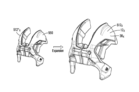
Figure 40 shows an example of a precursor 212x* of a post-molded expandable
component 212x being expanded to form the post-molded expandable component
212x
constituting a pad 36x. In this example, the pad 36x corresponds to the right
pad 364
that was shown previously in Figures 18 to 20. In this example of
implementation, the
post-molded expandable component 212x of the helmet 10 constituting the pad
36x
comprises an expandable material 250 that is molded into a precursor 212x *
which can
then be expanded by a stimulus (e.g., heat or another stimulus) to an expanded
shape
that is a scaled-up version of an initial shape of the precursor 212x*. Thus,
in this
example, a three-dimensional configuration of the initial shape of the
precursor 212x* is
such that, once the expandable material 250 is expanded, a three-dimensional
configuration of the expanded shape of the post-molded expandable component
212x
imparts a three-dimensional configuration of the pad 36x (e.g., including
curved and/or
angular parts of the pad 36x).
The post-molded expandable component 212x of the helmet 10 constituting the
pad 36x
is "expandable" in that it is capable of expanding and/or has been expanded by
a
36
CA 03140505 2021-11-15
WO 2020/232555
PCT/CA2020/050689
substantial degree in response to a stimulus after being molded. That is, an
expansion
ratio of the post-molded expandable component 212x of the helmet 10
constituting the
pad 36x, which refers to a ratio of a volume of the post-molded expandable
component
212x of the helmet 10 after the expandable material 250 has been expanded
subsequently to having been molded into the precursor 212x* over a volume of
the
precursor 212x* into which the expandable material 250 is initially molded,
may be
significantly high. For example, in some embodiments, the expansion ratio of
the post-
molded expandable component 212x of the helmet 10 constituting the pad 36x may
be
at least 2, in some cases at least 3, in some cases at least 5, in some cases
at least 10,
in some cases at least 20, in some cases at least 30, in some cases at least
40 and in
some cases even more (e.g., 45).
In such embodiments, the expandable material 250 can be any material capable
of
expanding after being molded. For example, the expandable material 250 may
include a
mixture of a polymeric substance 252 and an expansion agent 254 that allows
the
expandable material 250 to expand. Figure 41 is a block diagram representing
an
example of an expandable material of the post-molded expandable component.
Once
expanded into its final shape, the pad 36x may have desirable properties, such
as being
more shock-absorbent than it if had been made entirely of the expansion agent
254
and/or being lighter than if it had been made entirely of the polymeric
substance 252.
The polymeric substance 252 constitutes a substantial part of the expandable
material
250 and substantially contributes to structural integrity of the pad 36x. For
instance, in
some embodiments, the polymeric substance 252 may constitute at least 40%, in
some
cases at least 50%, in some cases at least 60%, in some cases at least 70%, in
some
cases at least 80%, and in some cases at least 90% of the expandable material
250 by
weight. In this example of implementation, the polymeric substance 252 may
constitute
between 50% and 90% of the expandable material 250 by weight.
37
CA 03140505 2021-11-15
WO 2020/232555
PCT/CA2020/050689
In this embodiment, the polymeric substance 252 may be an elastomeric
substance. For
instance, the polymeric substance 252 may be a thermoplastic elastomer (TPE)
or a
thermoset elastomer (TSE).
More particularly, in this embodiment, the polymeric substance 252 comprises
polyurethane. The polyurethane 252 may be composed of any suitable
constituents
such as isocyanates and polyols and possibly additives. For instance, in some
embodiments, the polyurethane 252 may have a hardness in a scale of Shore 00,
Shore
A, Shore C or Shore D, or equivalent. For example, in some embodiments, the
hardness of the polyurethane 252 may be between Shore 5A and 95A or between
Shore D 40D to 93D. Any other suitable polyurethane may be used in other
embodiments.
The polymeric substance 252 may comprise any other suitable polymer in other
embodiments. For example, in some embodiments, the polymeric substance 252 may
comprise silicon, rubber, ethylene-vinyl acetate (EVA), etc.
The expansion agent 254 is combined with the polyurethane 252 to enable
expansion of
the expandable material 250 to its final shape after it has been molded. A
quantity of the
expansion agent 254 allows the expandable material 250 to expand by a
substantial
degree after being molded. For instance, in some embodiments, the expansion
agent
254 may constitute at least 10%, in some cases at least 20%, in some cases at
least
30%, in some cases at least 40%, in some cases at least 50%, and in some cases
at
least 60%, of the expandable material 250 by weight and in some cases even
more. In
this example of implementation, the expansion agent 254 may constitute between
15%
and 50% of the expandable material 250 by weight. Controlling the quantity of
the
expansion agent 254 may allow control of the expansion ratio of the post-
molded
expandable component 212x.
In this embodiment, as shown in Figure 42, the expansion agent 254 comprises
an
amount of expandable microspheres 2601-260m. Each expandable microsphere 260i
38
CA 03140505 2021-11-15
WO 2020/232555
PCT/CA2020/050689
comprises a polymeric shell 262 expandable by a fluid encapsulated in an
interior of the
polymeric shell 262. In this example of implementation, the polymeric shell
262 of the
expandable microsphere 260i is a thermoplastic shell. The fluid encapsulated
in the
polymeric shell 262 is a liquid or gas (in this case a gas) able to expand the
expandable
microsphere 260i when heated during manufacturing of the pad 36x. In some
embodiments, the expandable microspheres 2601-260m may be ExpancelTM
microspheres commercialized by Akzo Nobel. In other embodiments, the
expandable
microspheres 2601-260m may be Dualite microspheres commercialized by Henkel;
Advancel I microspheres commercialized by Sekisui; Matsumoto Microsphere
microspheres commercialized by Matsumoto Yushi Seiyaku Co; or KUREHA
Microsphere microspheres commercialized by Kureha. Various other types of
expandable microspheres may be used in other embodiments.
In this example of implementation, the expandable microspheres 2601-260m
include dry
unexpanded (DU) microspheres when combined with the polymeric substance 252 to
create the expandable material 250 before the expandable material 250 is
molded and
subsequently expanded. For instance, the dry unexpanded (DU) microspheres may
be
provided as a powder mixed with one or more liquid constituents of the
polymeric
substance 252.
The expandable microspheres 2601-260m may be provided in various other forms
in
other embodiments. For example, in some embodiments, the expandable
microspheres
2601-260m may include dry expanded, wet and/or partially-expanded
microspheres. For
instance, wet unexpanded microspheres may be used to get better bonding with
the
polymeric substance 252. Partially-expanded microspheres may be used to employ
less
of the polymeric substance 252, mix with the polymeric substance 252 in semi-
solid
form, or reduce energy to be subsequently provided for expansion.
In some embodiments, the expandable microspheres 2601-260m may constitute at
least
10%, in some cases at least 20%, in some cases at least 30%, in some cases at
least
40%, in some cases at least 50%, and in some cases at least 60%of the
expandable
39
CA 03140505 2021-11-15
WO 2020/232555
PCT/CA2020/050689
material 250 by weight and in some cases even more. In this example of
implementation, the expandable microspheres 2601-260m may constitute between
15%
and 50% of the expandable material 250 by weight.
The post-molded expandable component 212x of the helmet 10 constituting the
pad 36x
may have various desirable qualities.
For instance, in some embodiments, the pad 36x may be less dense and thus
lighter
than if it was entirely made of the polyurethane 252, yet be more shock-
absorbent
and/or have other better mechanical properties than if it was entirely made of
the
expandable microspheres 2601-260m.
For example, in some embodiments, a density of the expandable material 250 of
the
pad 36x may be less than a density of the polyurethane 252 (alone). For
instance, the
density of the expandable material 250 of the pad 36x may be no more than 70%,
in
some cases no more than 60%, in some cases no more than 50%, in some cases no
more than 40%, in some cases no more than 30%, in some cases no more than 20%,
in
some cases no more than 10%, and in some cases no more than 5% of the density
of
the polyurethane 252 and in some cases even less. For example, in some
embodiments, the density of the expandable material 250 of the pad 36x may be
between 2 to 75 times less than the density of the polyurethane 252 ,i.e., the
density of
the expandable material 250 of the pad 36x may be about 1% to 50% of the
density of
the polyurethane 252).
The density of the expandable material 250 of the pad 36x may have any
suitable value.
For instance, in some embodiments, the density of the expandable material 250
of the
pad 36x may be no more than 0.7 g/cm3, in some cases no more than 0.4 g/cm3,
in
some cases no more than 0.1 g/cm3, in some cases no more than 0.080 g/cm3, in
some
cases no more than 0.050 g/cm3, in some cases no more than 0.030 g/cm3, and/or
may
be at least 0.010 g/cm3. In some examples of implementation, the density of
the
expandable material 250 may be between 0.015 g/cm3 and 0.080 g/cm3, in some
cases
CA 03140505 2021-11-15
WO 2020/232555
PCT/CA2020/050689
between 0.030 g/cm3 and 0.070 g/cm3, and in some cases between 0.040 gicm3 and
0.060 gicm3.
As another example, in some embodiments, a stiffness of the expandable
material 250
of the pad 36x may be different from (i.e., greater or less than) a stiffness
of the
expandable microspheres 2601-260m (alone). For instance, a modulus of
elasticity (i.e.,
Young's modulus) of the expandable material 250 of the pad 36x may be greater
or less
than a modulus of elasticity of the expandable microspheres 2601-260m (alone).
For
instance, a difference between the modulus of elasticity of the expandable
material 250
of the pad 36x and the modulus of elasticity of the expandable microspheres
2601-260m
may be at least 20%, in some cases at least 30%, in some cases at least 50%,
and in
some cases even more, measured based on a smaller one of the modulus of
elasticity
of the expandable material 250 of the pad 36x and the modulus of elasticity of
the
expandable microspheres 2601-260m. In some cases, the modulus of elasticity
may be
evaluated according to ASTM D-638 or ASTM D-412.
As another example, in some embodiments, a resilience of the expandable
material 250
of the pad 36x may be less than a resilience of the expandable microspheres
2601-260m
(alone). For instance, in some embodiments, the resilience of the expandable
material
250 of the pad 36x may be no more than 70%, in some cases no more than 60%, in
some cases no more than 50%, in some cases no more than 40%, in some cases no
more than 30%, in some cases no more than 20%, and in some cases no more than
10% of the resilience of the expandable microspheres 2601-260m according to
ASTM
D2632-01 which measures resilience by vertical rebound. In some examples of
implementation, the resilience of the expandable material 250 of the pad 36x
may be
between 20% and 60% of the resilience of the expandable microspheres 2601-
260m.
Alternatively, in other embodiments, the resilience of the expandable material
250 of the
pad 36x may be greater than the resilience of the expandable microspheres 2601-
260m.
The resilience of the expandable material 250 of the pad 36x may have any
suitable
value. For instance, in some embodiments, the resilience of the expandable
material
41
CA 03140505 2021-11-15
WO 2020/232555
PCT/CA2020/050689
250 of the pad 36x may be no more than 40%, in some cases no more than 30%, in
some cases no more than 20%, in some cases no more than 10% and in some cases
even less (e.g., 5%), according to ASTM D2632-01, thereby making the pad 36x
more
shock-absorbent. In other embodiments, the resilience of the expandable
material 50 of
the pad 36x may be at least 60%, in some cases at least 70%, in some cases at
least
80% and in some cases even more, according to ASTM D2632-01, thereby making
the
expandable material 250 provide more rebound.
As another example, in some embodiments, a tensile strength of the expandable
material 250 of the pad 36x may be greater than a tensile strength of the
expandable
microspheres 2601-260m (alone). For instance, in some embodiments, the tensile
strength of the expandable material 250 of the pad 36x may be at least 120%,
in some
cases at least 150%, in some cases at least 200%, in some cases at least 300%,
in
some cases at least 400%, and in some cases at least 500% of the tensile
strength of
the expandable microspheres 2601-260m according to ASTM D-638 or ASTM D-412,
and in some cases even more.
The tensile strength of the expandable material 250 of the pad 36x may have
any
suitable value. For instance, in some embodiments, the tensile strength of the
expandable material 250 of the pad 36x may be at least 0.9 MPa, in some cases
at least
1 MPa, in some cases at least 1.2 MPa, in some cases at least 1.5 MPa and in
some
cases even more (e.g. 2 MPa or more).
As another example, in some embodiments, an elongation at break of the
expandable
material 250 of the pad 36x may be greater than an elongation at break of the
expandable microspheres 2601-260m (alone). For instance, in some embodiments,
the
elongation at break of the expandable material 250 of the pad 36x may be at
least
120%, in some cases at least 150%, in some cases at least 200%, in some cases
at
least 300%, in some cases at least 400%, and in some cases at least 500% of
the
elongation at break of the expandable microspheres 2601-260m according to ASTM
D-
638 or ASTM D-412, and in some cases even more.
42
CA 03140505 2021-11-15
WO 2020/232555
PCT/CA2020/050689
The elongation at break of the expandable material 250 of the pad 36x may have
any
suitable value. For instance, in some embodiments, the elongation at break of
the
expandable material 250 of the pad 36x may be at least 20%, in some cases at
least
30%, in some cases at least 50%, in some cases at least 75%, in some cases at
least
100%, and in some cases even more (e.g. 150% or more).
With additional reference to Figure 40, in this example of implementation the
post-
molded expandable component 212x constituting the pad 36x includes an
additively
manufactured component 12x. For example, the precursor 212x* of the post-
molded
expandable component 212x may be molded around the additively manufactured
component 12x. In some embodiments, the additively manufactured component 12x
may include a lattice with an open structure. In such embodiments, the
expandable
material 250 may extend at least partially into/through the additively
manufactured
component 12x.
Figure 43 shows a cross-sectional view of a sport helmet 10 with inner padding
15 that
includes additively manufactured components 121-124 integrated into post-
molded
expandable components 2121-2124 constituting pads 361-364. In this example of
implementation, the additively manufactured component 121-124 are made from
additively manufactured material 50 and act as a reinforcing structure or
armature for
the post-molded expandable components 2121-2124.
In some embodiments, an AM component may comprise expandable material. For
example, rather than being molded and then expanded through a post-molded
expansion process like the one discussed above with reference to Figures 40 to
43, an
expandable component may instead be additively manufactured by additively-
manufacturing a precursor and then expanding the precursor into a post-
additively-
manufactured (post-AM) expandable component through a post-AM expansion
process.
43
CA 03140505 2021-11-15
WO 2020/232555
PCT/CA2020/050689
For example, referring again to Figures 18 to 20, the inner padding 15 of the
helmet 10
may include post-AM expandable components 512 constituting the pads 361 to
36x.
Utilizing post-AM expandable components has many potential benefits, such as
potentially reducing the time required for the additive-manufacturing, because
the
physical size of the precursor is potentially many times smaller than that of
the fully
expanded component. For example, the additional time required to expand a post-
AM
precursor into a post-AM expandable component may be more than offset by a
reduction in time required to additively-manufacture the physically smaller
precursor.
Furthermore, and the use of post-AM expandable components may also allow
components to be made lighter/less dense for a given volume while still
satisfying other
desirable performance characteristics, such as impact absorption, resiliency,
structural
integrity, etc.
Figure 44 shows an example of a precursor 512x* of a post-AM expandable
component
512x being expanded to form the post-AM expandable component 512x constituting
a
pad 36x. In this example, the pad 36x corresponds to the left and right pads
363 and
364 that were shown previously in Figures 18 to 20. In this example of
implementation,
the post-AM expandable component 512x of the helmet 10 constituting the pad
36x
comprises an expandable material 550 that is additively-manufactured into a
precursor
512x* which can then be expanded by a stimulus (e.g., heat or another
stimulus) to an
expanded shape that is a scaled-up version of an initial shape of the
precursor 512x*.
Thus, in this example, a three-dimensional configuration of the initial shape
of the
precursor 512x* is such that, once the expandable material 550 is expanded, a
three-
dimensional configuration of the expanded shape of the post-AM expandable
component 512x imparts a three-dimensional configuration of the pad 36x (e.g.,
including curved and/or angular parts of the pad 36x).
The post-AM expandable component 512x of the helmet 10 constituting the pad
36x is
"expandable" in that it is capable of expanding and/or has been expanded by a
substantial degree in response to a stimulus after being additively-
manufactured. That
is, an expansion ratio of the post-AM expandable component 512x of the helmet
10
44
CA 03140505 2021-11-15
WO 2020/232555
PCT/CA2020/050689
constituting the pad 36x, which refers to a ratio of a volume of the post-AM
expandable
component 512x of the helmet 10 after the expandable material 550 has been
expanded
subsequently to having been additively-manufactured into the precursor 512x*
over a
volume of the precursor 512x * into which the expandable material 550 is
initially
.. additively-manufactured, may be significantly high. For example, in some
embodiments,
the expansion ratio of the post-AM expandable component 512x of the helmet 10
constituting the pad 36x may be at least 2, in some cases at least 3, in some
cases at
least 5, in some cases at least 10, in some cases at least 20, in some cases
at least 30,
in some cases at least 40 and in some cases even more (e.g., 45).
In such embodiments, the expandable material 550 can be any material capable
of
expanding after being additively-manufactured. For example, the expandable
material
550 may include a mixture of a polymeric substance and an expansion agent that
allows
the expandable material 550 to expand after an additive manufacturing step has
been
done to form the expandable material 550 into a precursor component. Once
expanded
into its final shape, the pad 36x may have desirable properties, such as being
more
shock-absorbent than it if had been made entirely of the expansion agent
and/or being
lighter than if it had been made entirely of the polymeric substance.
In some embodiments, a polymeric substance may constitute a substantial part
of the
expandable material 550 and may substantially contribute to structural
integrity of the
pad 36x. For instance, in some embodiments, a polymeric substance may
constitute at
least 40%, in some cases at least 50%, in some cases at least 60%, in some
cases at
least 70%, in some cases at least 80%, and in some cases at least 90% of the
expandable material 550 by weight.
In some embodiments, the expandable material 550 may comprise a polymeric
substance that is elastomeric. For instance, the expandable material 550 may
comprise
a polymeric substance such as a thermoplastic elastomer (TPE) or a thermoset
elastomer (TSE). In some embodiments, the polymeric substance may comprise
polyurethane. The polyurethane may be composed of any suitable constituents
such as
CA 03140505 2021-11-15
WO 2020/232555
PCT/CA2020/050689
isocyanates and polyols and possibly additives. For instance, in some
embodiments,
the polyurethane may have a hardness in a scale of Shore 00, Shore A, Shore C
or
Shore D, or equivalent. For example, in some embodiments, the hardness of the
polyurethane may be between Shore 5A and 95A or between Shore D 40D to 93D.
Any
other suitable polyurethane may be used in other embodiments.
In other embodiments, the expandable material 550 may comprises any other
suitable
polymer in other embodiments. For example, in some embodiments, the expandable
material 550 may include a polymeric substance such as silicon, rubber, etc.
In some embodiments an expansion agent may be combined with a polymeric
substance, such as polyurethane, to enable expansion of the expandable
material 550
to its final shape after the precursor 512x* has been additively-manufactured.
A quantity of the expansion agent allows the expandable material 550 to expand
by a
substantial degree after being additively-manufactured to form the precursor
512x*. For
instance, in some embodiments, the expansion agent may constitute at least
10%, in
some cases at least 20%, in some cases at least 30%, in some cases at least
40%, in
some cases at least 50%, and in some cases at least 60%, of the expandable
material
550 by weight and in some cases even more. Controlling the quantity of the
expansion
agent may allow control of the expansion ratio of the post-AM expandable
component 5
12x.
The post-AM expandable component 512x of the helmet 10 constituting the pad
36x
may have various desirable qualities similar to the post-molded expandable
component
212x described earlier.
In some embodiments, the combining of the polymeric substance and the
expansion
agent occurs during the additive-manufacturing process, and there is an
intermediary
polymerizing step to polymerize the polymeric substance and the expansion
agent
before the further step of expansion of the precursor 512x* into the post-AM
expandable
46
CA 03140505 2021-11-15
WO 2020/232555
PCT/CA2020/050689
component 512x. For example, the intermediate polymerizing step might involve
applying heat, light or some other form of energy to the preliminary formed
combination
of the polymeric substance and the expansion agent in order to promote
polymerization
without causing expansion.
The additive manufacturing technology utilized in such embodiments could
include any
one or more of the additive manufacturing technologies discussed earlier. For
instance,
in one example of implementation, a vat photopolymerization AM technology,
such as
SLA, DLP or CDLP may be used to light-cure a mixture of a polymeric substance
and
an expansion agent. For example, in such embodiments, a planetary mixer or any
other
suitable mixer may be used to first mix the polymeric substance (e.g.,
polyurethane or
acrylic) with the expansion agent (e.g., expandable microspheres, such as
unexpanded
Expancel, Dualite microspheres, Advancell microspheres, etc.), and then a SLA,
DLP or
CDLP type 3D printer may be used to light-cure the polymeric substance /
expansion
agent mixture to consolidate the material into a preliminary form. In such
embodiments,
final polymerization of the polymeric substance / expansion agent mixture may
be done
using a heat and/or light source that does not reach the expansion temperature
of the
expansion agent so that the temperature of the expandable material during the
additive-
manufacturing is lower than the expansion temperature of the expansion agent.
For
instance, in some embodiments where the expansion temperature of the expansion
agent may be 70 C or more, the additive-manufacturing process may be carried
out
such that the temperature of the expandable material 550 being additively-
manufactured into the precursor 512x* is less than 70 C (e.g., 40 C). Once
the
polymerization step has been completed, the expansion phase may be activated
by
using a heat source to raise the temperature of the expandable material 550
above the
expansion temperature of the expansion agent.
Other AM technologies may be used to additively-manufacture expandable
components
in other embodiments. For example, Figure 45 shows an example of a binder
jetting 3D
printer system 500 being used to additively manufacture a precursor 512x* of a
post-AM
expandable component 512x in accordance with another embodiment of the present
47
CA 03140505 2021-11-15
WO 2020/232555
PCT/CA2020/050689
disclosure. In binder jetting, a binder is selectively deposited onto a bed of
powder to
selectively bond areas together to form solid parts layer-by-layer. The binder
jetting 3D
printer system 500 includes a build platform 502, a recoating blade 506 and a
binder
nozzle carriage 508. In operation, the recoating blade 506 first spreads a bed
or layer
of powder expansion agent 504 (e.g., unexpanded Expancel, Dualite
microspheres,
Advancell microspheres, etc.) over the build platform 502. Then, the binder
jetting
nozzle carriage 508, which includes jetting nozzles similar to the nozzles
used in
desktop inkjet 2D printers, is moved over the powder bed 504 and the nozzles
are
controlled to selectively deposit droplets of a binding agent (e.g., a
polymeric substance
such as polyurethane) that bonds the powder particles of the expansion agent
together.
When a layer is complete, the build platform 502 moves downwards and the
recoating
blade 506 spreads a new layer of powder expansion agent 504 to re-coat the
powder
bed. This process then repeats until the preliminary form of the precursor
512x* is
complete. After printing, the preliminary form of the precursor 512x* may be
removed
from the powder bed and unbound, excess powder expansion agent may be removed
via pressurized air. Similar to the previous vat photopolymerization example,
the final
polymerization or curing of the preliminary form of the precursor 512x* may be
done
using a heat source that does not reach the expansion temperature of the
expansion
agent. For instance, in some embodiments where the expansion temperature of
the
expansion agent may be 70 C or more, the preliminary form of the precursor
512x* may
be cured in an oven at 50-60 C after being removed from the powder bed. Once
the
polymerization step has been completed and the precursor 512x* has been cured,
the
expansion phase may be activated by raising the temperature of the expandable
material 550 above the expansion temperature of the expansion agent.
Referring again to the example embodiment of a sport helmet 10 shown in Figure
43, it
is noted that, in addition to the inner padding 15, in this embodiment the
helmet 10 also
includes comfort pads 371-374. In some embodiments, the comfort pads 371-374
may
also or instead include additively manufactured components. For example, in
some
embodiments, the additively manufactured components 12x of the helmet 10 may
instead constitute the comfort pads 37x.
48
CA 03140505 2021-11-15
WO 2020/232555
PCT/CA2020/050689
Figure 46 shows an exploded view of an example of inner padding 15 for a sport
helmet
in which the comfort pads 37x include additively manufactured components 12x.
In
particular, in this example of implementation, the inner padding 15 includes
absorption
pads 361-36A, and additively manufactured components 121-12K constituting
comfort
pads 371-37K. In this example of implementation, the comfort pads 371-37K are
made
from an additively manufactured material 50, which, in some embodiments, could
be an
expandable material 550 as described above. In contrast, the absorption pads
361-36A
may be made from a more conventional non-additively manufactured material 350,
such
as EPP or Expancel.
In some embodiments, the comfort pads 371-37K are configured for low energy
levels
that reach a targeted 35 shore 00 durometer or less. Since additively
manufactured
material 50 can be a solid material rather than a material with an open cell
structure,
such as many conventional memory foams, implementing the comfort pads 371-37K
with
additively manufactured components 121-12K may address the water absorption
problem that often occurs when materials with open cell structures are used
for comfort
padding parts in order to provide a desired level of comfort. For example, in
some
embodiments a relatively low hardness and feel to provide a desired level of
comfort
could be achieved by using a relatively small mesh lattice structure with
relatively thin
elongate members.
Figure 47 shows a cross-sectional view of a portion of the inner padding of
Figure 46
showing that the additively manufactured component 122 constituting the
comfort pad
372 lies between the wearer's head and the absorption pad 361 when the helmet
10 is
worn. In some embodiments the comfort pads 371-37K may be affixed to the
absorption
pads 361-36A. In other embodiments the comfort pads may be otherwise affixed
to the
helmet, but may be moveable relative to the absorption pads. In some
embodiments,
the comfort pads may also or instead be moveable relative to one another,
e.g., during
adjustment of the fit of the helmet and/or as a result of deflection of the
helmet due to an
impact.
49
CA 03140505 2021-11-15
WO 2020/232555
PCT/CA2020/050689
As noted above with reference to the example hockey helmet 10 shown in Figures
10-
20, in some embodiments the shock-absorbing materials used in the liner 15 may
include liquid crystal elastomer (LCE) components in order to enhance their
impact
absorbing performance, e.g., to provide better impact energy dissipation. A
mesogen is
a compound that displays liquid crystal properties. Mesogens can be described
as
disordered solids or ordered liquids because they arise from a unique state of
matter
that exhibits both solid-like and liquid-like properties called the liquid
crystalline state.
This liquid crystalline state is called the mesophase and occurs between the
crystalline
.. solid state and the isotropic liquid state at distinct temperature ranges.
LCEs are
materials that are made up of slightly crosslinked liquid crystalline polymer
networks.
LCE materials combine the entropy elasticity of an elastomer with the
self-
organization of a liquid crystalline phase. In LCEs, the mesogens can either
be part of
the polymer chain (main-chain liquid crystalline elastomers) or they are
attached via
.. an alkyl spacer (side-chain liquid crystalline elastomers).
Figure 48A shows an example of a main-chain LCE material 400 in which the
mesogens 404 are part of polymer chains 402 that are slightly crosslinked at
crosslinks
406. As shown in Figure 48A, when the LCE material 400 is uncompressed the
mesogenic groups 404 are generally aligned. When a compressive force is
applied to
the LCE material 400, as shown in Figure 48B, the mesogenic groups 404 are
displaced
out of alignment. The displacement of the mesogenic groups 404 serves to
elastically
dissipate the energy of the applied force and afterward return to
substantially the same
state as shown in Figure 48A. In this way, many LCE materials provide better
impact
absorbing performance relative to conventional shock-absorbing materials such
as
polymeric foam
In some embodiments, one or more of the pads 36x of the liner 15 for a helmet
10 may
have a hybrid structure that includes a combination of shock-absorbing
materials, such
as non-AM LCE materials/components, AM LCE materials/components (e.g., 3D
printed
LCE components) and/or more conventional shock-absorbing materials/components
CA 03140505 2021-11-15
WO 2020/232555
PCT/CA2020/050689
(e.g., EPP foram, EPS foam, PORON XRD foam, etc.) that may be fabricated using
non-AM and/or AM technologies. For example, Figure 49 shows an example of a
pad
36x in which multiple column- or cylinder-shaped LCE components 400 are
embedded
in a polymeric foam structure constituting the remainder of the pad 36x. The
column-
shaped LCE components 400 are arranged such that the elongated dimension of
each
column extends in a direction that is generally radial to a wearer's head.
Although the
LCE components are cylindrical or column-shaped in this example, more
generally LCE
components or other shock-absorbing materials that are utilized in a hybrid
structure
may be any suitable shape, e.g., in some embodiments one or more of the shock-
absorbing materials in a hybrid structure may be designed to provide optimized
attenuation under impact (specific buckling, twisting, collapsing).
In this example shown in Figure 49, the pad 36x forms part of the side padding
for a
helmet and the LCE components 400 are located in a portion of the pad 36x that
would
face the wearer's temple region when the helmet is worn in order to enhance
lateral
impact absorption. In other embodiments, LCE components may also or instead be
incorporated into padding that faces other portions of the wearer's head, such
as the
front region, top region, back region and/or occipital region. In some
embodiments, the
LCE components used in different regions of the helmet may be configured with
different shapes, sizes and/or materials in order to provide different impact-
absorbing
properties in different regions.
In some embodiments, the additively manufactured components 12x constituting
the
pads 36x and/or the comfort pads 37x of the helmet 10 may have LCE components
integrated into the pads. For example, Figure 50 shows an example of an AM
component 12x that has a lattice structure into which a cluster of four column-
shaped
LCE components 400 have been embedded. The four LCE components 400 have been
thinly outlined in Figure 50 in order to allow them to be more easily
identified in the
image. In some embodiments, the lattice structure of the AM component 12x may
be
formed from a shock-absorbing material that includes a polymeric foam and/or a
polymeric structure comprising one or more polymeric materials, while the LCE
51
CA 03140505 2021-11-15
WO 2020/232555
PCT/CA2020/050689
components 400 may include any suitable LCE material. The column shape of the
LCE
components in this example is merely illustrative of one example shape that
may be
used in some embodiments. Differently shaped and/or sized LCE components may
be
used in other embodiments. In some embodiments, the spaces in the AM component
12x for receiving and retaining the LCE components 400 may be formed in the AM
component 12x during the additive manufacturing process. In other embodiments,
the
spaces may be created after the additive manufacturing process, e.g., by
drilling or
cutting into the AM component 12x to create the spaces.
One of the common problems that is encountered when designing helmet
liner/padding
parts is air channel integration. It is often desirable to provide a high
level of ventilation,
but conventional molding techniques that have traditionally been used to
manufactured
helmet liner/padding parts limit the types of structures that can practically
be realized.
The use of additively manufactured components with lattice structures to
implement
liner/padding parts may solve some of these problems, because a lattice can be
implemented as an open structure that permits air flow. However, in
some
embodiments, a desired level of ventilation may be achieved by also or instead
using
non-lattice additively manufactured components that have air channels formed
in and/or
on them that could not be practically mouldable by traditional molding. For
example, in
some embodiments the additively manufactured components 12x constituting the
pads
36x and/or the comfort pads 37x of the helmet 10 may have air channels
integrated in
the core of the pads.
Figure 51 shows a cross-sectional view of a sport helmet 10 with inner padding
that
includes air channels 39 integrally formed within additively manufactured
components
121, 123, 124 constituting the absorption pads 361, 363, 364 of the inner
padding. The
outer shell 11 of the helmet 10 may include apertures (not shown in Figure 51)
that
allow air in the air channels 39 to exit the helmet 10. Similarly, the
absorption pads 361,
363, 364 may include apertures (not shown in Figure 51) that permit heated air
from the
interior of the helmet to pass into the air channels 39 in order eventually
exit the helmet
10. For example, portions of the absorption pads 361, 363, 364 nearest the
wearer's
52
CA 03140505 2021-11-15
WO 2020/232555
PCT/CA2020/050689
head when the helmet is worn may have an open lattice structure to permit this
air flow
from the interior of the helmet into the air channels 39. In such embodiments,
portions
of the absorption pads 361, 363, 364 furthest from the wearer's head when the
helmet 10
is worn, i.e., the portions of the absorption pads 361, 363, 364 proximal the
outer shell 11
may be manufactured with a solid non-lattice structure. In other embodiments,
the
absorption pads 361, 363, 364 may be wholly formed with a solid non-lattice
structure. In
other embodiments, the absorption pads 361, 363, 364 may be wholly formed with
a
lattice structure. In such embodiments, the cross-sectional area of the air
channels 39
may be greater than the cross-sectional area of spaces between elongate
members of
the lattice structure itself.
While in many of the embodiments described above the inner liner 15 of the
helmet 10
comprises the AM components 121-12A, in other embodiments, another part of the
helmet 10 may comprise one or more AM components such as the AM components
121-12A. For instance, in some embodiments, as shown in Figure 52, when the
helmet
10 comprises a faceguard 14, the faceguard 14 and/or a chin cup 112 mounted to
the
chin strap 16 of the helmet 10 to engage a chin of the user may comprise an AM
component constructed using principles described here in respect of the AM
components 121-12A. A cage or visor faceguard 14 comprising an AM component
may
have several advantages relative to a conventional faceguard. For example, a
conventional cage faceguard is typically manufactured by welding together a
plurality of
elongate metal members to form a cage. In the conventional cage faceguard, the
elongate metal members are welded together where they overlap. These welds are
a
potential point of failure. In contrast, as shown in Figure 52, in an
additively-
manufactured cage faceguard 14, the vertically oriented elongate members 113
may
directly intersect the horizontally oriented elongate members 117 at points of
intersection 115. In addition, the use of additive-manufacturing makes it
feasible to
customize the positioning and/or profile of the elongate members 113, 115 of
the
faceguard 14. For example, the positioning of the elongate members 113,115 may
be
customized based on the eye positions of an intended user (e.g., pupillary
distance,
location of eyes relative to the top and/or sides of the head, etc.).
Furthermore, the
53
CA 03140505 2021-11-15
WO 2020/232555
PCT/CA2020/050689
profiles of the elongate members 113,115 of the faceguard may be tapered
and/or
shaped to minimize their impact on the user's field of vision. For example,
portions of
the elongate members 113,115 that may fall within the user's field of vision
may have
an ovoid cross-section, with a major axis of the ovoid oriented substantially
parallel with
the user's line of sight.
Figures 53A, 53B and 53C show another example of an additively-manufactured
cage
faceguard 14. In this example, the additively-manufactured cage faceguard 14
has
been formed by 3D printing metal and is configured as a faceguard for a goalie
mask.
Similar to the faceguard 14 shown in Figure 52, the example implementation of
a
faceguard 14 shown in Figures 53A-C includes elongate members 113 and 117 that
merge into one another at points of intersection 115.
In some embodiments, at least part of the outer shell 11 may comprise an AM
component that is similar to the AM components 121-12A. For instance, a given
one of
the front shell member 22 and the rear shell member 24 of the outer shell 11
may
comprise an AM component.
Although in embodiments considered above the helmet 10 is a hockey helmet, in
other
embodiments, the helmet 10 may be any other helmet usable by a player playing
another type of contact sport (e.g., a "full-contact" sport) in which there
are significant
impact forces on the player due to player-to-player and/or player-to-object
contact or
any other type of sports, including athletic activities other than contact
sports.
For example, in other embodiments, as shown in Figure 54, the helmet 10 may be
a
lacrosse helmet. The lacrosse helmet 10 comprises a chin piece 72 extending
from the
left lateral side portion 25L to the right lateral side portion 25R of the
helmet 10 and
configured to extend in front of a chin area of the user. The lacrosse helmet
10 also
comprises the faceguard 14 which is connected to the shell 11 and the chin
piece 72.
54
CA 03140505 2021-11-15
WO 2020/232555
PCT/CA2020/050689
The lacrosse helmet 10 may be constructed according to principles discussed
herein.
For example, in some embodiments, the lacrosse helmet 10 may the additively-
manufactured components 121-12A, as discussed above. For instance, in some
embodiments, the additively-manufactured components 121-12A may constitute at
least
part of the shell 11, at least part of the liner 15, at least part of the chin
piece 72, and/or
at least part of the faceguard 14, according to principles discussed herein.
In other embodiments, the helmet 10 may be a baseball/softball helmet or any
other
type of helmet.
While in many of the embodiments described above it is the inner liner 15 of a
helmet
10 that comprises an AM component, in other embodiments, another part of the
helmet
10 may comprise one or more AM components. For instance, referring again to
Figure
5, in some embodiments when the helmet 10 comprises a faceguard 14, a chin cup
112
mounted to the chin strap 16 of the helmet 10 to engage a chin of the user may
comprise a post-AM expandable component constructed using principles described
here in respect of the post-AM expandable component 512x described herein. In
some
embodiments, at least part of the outer shell 11 may comprise a post-AM
expandable
component that is similar to the post-AM expandable component 512x. For
instance, a
given one of the front shell member 22 and the rear shell member 24 of the
outer shell
11 may comprise a post-AM expandable component.
Moreover, although in many of the embodiments described above the article of
protective athletic gear comprising an AM component is a helmet, in other
embodiments, the article of protective athletic gear may be any other article
of
protective athletic gear comprising one or more AM components. For example,
with
reference again to Figure 33, in some embodiments the example implementation
of an
additively manufactured shoulder pad shown in Figure 33 may be constructed as
a
post-AM expandable component using principles described herein in respect of
the
post-AM expandable component 512x.
CA 03140505 2021-11-15
WO 2020/232555
PCT/CA2020/050689
In other embodiments, the article of manufacture that includes AM components
may be
some other form of athletic gear. For example, in some embodiments the article
comprising additively-manufactured components may be a sporting implement for
use
by a user engaging in a sport.
Figure 55 shows an embodiment of a sporting implement 10 for use by a user
engaging
in a sport. The sporting implement 10 comprises an elongate holdable member 12
configured to be held by the user and an object-contacting member 14
configured to
contact an object (e.g., a puck or ball) intended to be moved in the sport. In
this
embodiment, the sport is hockey and the sporting implement 10 is a hockey
stick for
use by the user, who is a hockey player, to pass, shoot or otherwise move a
puck or
ball. The elongate holdable member 12 of the hockey stick 10 is a shaft, which
comprises a handle 20 of the hockey stick 10, and the object-contacting member
14 of
the hockey stick 10 is a blade.
In this embodiment, as further discussed later, the hockey stick 10 is
designed to
enhance its use, performance and/or manufacturing, including, for example, by
being
lightweight, having improved strength, flex, stiffness, impact resistance
and/or other
properties, reducing scrap or waste during its construction, and/or enhancing
other
aspects of the hockey stick 10. For instance, in some embodiments, the hockey
stick 10
may include a structure that is open, such as by being latticed (e.g.,
trussed), and/or
made by additive manufacturing, selective material positioning, etc.
The shaft 12 is configured to be held by the player to use the hockey stick
10. A
periphery 30 of the shaft 12 includes a front surface 16 and a rear surface 18
opposite
one another, as well as a top surface 22 and a bottom surface 24 opposite one
another.
Proximal and distal end portions 26, 28 of the shaft 12 are spaced apart in a
longitudinal
direction of the shaft 12, respectively adjacent to the handle 20 and the
blade 14, and
define a length of the shaft 12. A length of the hockey stick 10 is measured
from a
proximal end 34 of the shaft 12 along the top surface 22 of the shaft 12
through the
blade 14.
56
CA 03140505 2021-11-15
WO 2020/232555
PCT/CA2020/050689
A cross-section of the shaft 12 may have any suitable configuration. For
instance, in this
embodiment, the cross-section of the shaft 12 has a major axis 36 which
defines a
major dimension D of the shaft's cross-section and a minor axis 38 which
defines a
minor dimension W of the shaft's cross-section. In this example, the cross-
section of the
shaft 12 is generally polygonal. More particularly, in this example, the cross-
section of
the shaft 12 is generally rectangular, with the front surface 16, the rear
surface 18, the
top surface 22, and the bottom surface 24 being generally flat. Corners
between these
surfaces of the shaft 12 may be rounded or beveled.
The shaft 12 may have any other suitable shape and/or be constructed in any
other
suitable way in other embodiments. For example, in some embodiments, the cross-
section of the shaft 12 may have any other suitable shape (e.g., the front
surface 16, the
rear surface 18, the top surface 22, and/or the bottom surface 24 may be
curved and/or
angular and/or have any other suitable shape, possibly including two or more
sides or
segments oriented differently, such that the cross-section of the shaft 12 may
be
pentagonal, hexagonal, heptagonal, octagonal, partly or fully curved, etc.).
As another
example, the cross-section of the shaft 12 may vary along the length of the
shaft 12.
The blade 14 is configured to allow the player to pass, shoot or otherwise
move the
puck or ball. A periphery 50 of the blade 14 comprises a front surface 52 and
a rear
surface 54 opposite one another, as well as a top edge 56, a toe edge 58, a
heel edge
59, and a bottom edge 60. The blade 14 comprises a toe region 61, a heel
region 62,
and an intermediate region 63 between the toe region 61 and the heel region
62. The
blade 14 has a longitudinal direction that defines a length of the blade 14, a
thicknesswise direction that is normal to the longitudinal direction and
defines a
thickness of the blade 14, and a heightwise direction that is normal to the
longitudinal
direction and defines a height of the blade 14.
A cross-section of the blade 14 may have any suitable configuration. For
instance, in
this embodiment, the cross-section of the blade 14 varies along the
longitudinal
57
CA 03140505 2021-11-15
WO 2020/232555
PCT/CA2020/050689
direction of the blade 14 (e.g., tapers towards the toe region 61 of the blade
14), with
the front surface 52 and the rear surface 54 curving so that the front surface
52 is
concave and the rear surface 54 is convex. Corners between the front surface
52, the
rear surface 54, the top edge 56, the toe edge 58, the heel edge 59, and the
bottom
edge 60 may be rounded or beveled.
The blade 14 may have any other suitable shape and/or be constructed in any
other
suitable way in other embodiments. For example, in some embodiments, the cross-
section of the blade 14 may have any other suitable shape (e.g., the front
surface 52,
the rear surface 54, the top edge 56, the toe edge 58, the heel edge 59, and
the bottom
edge 60 may be curved differently and/or angular and/or have any other
suitable shape,
etc.).
The shaft 12 and the blade 14 may be interconnected in any suitable way. For
instance,
in this embodiment, the shaft 12 and the blade 14 are integrally formed with
one another
(i.e., at least part of the shaft 12 and at least of the blade 14 are
integrally formed
together) such that they constitute a one-piece stick. In other embodiments,
the blade
14 may be secured to and removable from the shaft 12 (e.g., by inserting a
shank of the
blade 14, which may include a tenon, into a cavity of the shaft 12).
In this embodiment, the hockey stick 10 includes an open structure 68 and a
covering
69 that covers at least part of the open structure 68. This may reduce a
weight of the
hockey stick 10, enhance properties such as the strength, the stiffness, the
flex, the
impact resistance, and/or other characteristics of the hockey stick 10, etc.
More particularly, in this embodiment, at least part of the hockey stick 10 is
latticed, i.e.,
comprises a lattice 70. Thus, in this example, the lattice 70 constitutes at
least part of
the shaft 12 and/or at least part of the blade 14. Specifically, in this
example, the shaft
12 includes a portion 71 of the lattice 70, while the blade 14 includes
another portion 73
of the lattice 70. In this embodiment, the lattice 70 occupies at least a
majority (i.e., a
58
CA 03140505 2021-11-15
WO 2020/232555
PCT/CA2020/050689
majority or an entirety) of the length of the shaft 12 and at least a majority
(i.e., a
majority or an entirety) of the length of the blade 14.
In some embodiments, the lattice 70 comprises a framework of structural
members 411-
41 E that intersect one another. In some embodiments, the structural members
411-41E
may be arranged in a regular arrangement repeating over the lattice 70. In
some cases,
the lattice 70 may be viewed as made up of unit cells 371-37c each including a
subset of
the structural members 411-41E that forms the regular arrangement repeating
over the
lattice 70. Each of these unit cells 371-37c can be viewed as having a voxel,
which
refers to a notional three-dimensional space that it occupies. In other
embodiments, the
structural members 411-41E may be arranged in different arrangements over the
lattice
70 (e.g., which do not necessarily repeat over the lattice 70, do not
necessarily define
unit cells, etc.).
.. The lattice 70, including its structural members 411-41E, may be configured
in any
suitable way.
In this embodiment, the structural members 411-41E are elongate members that
intersect one another at nodes 421-42N. The elongate members 411-41E may
sometimes
be referred to as "beams" or "struts". Each of the elongate members 411-41E
may be
straight, curved, or partly straight and partly curved. While in some
embodiments at
least some of the nodes 421-42N (i.e. some of the nodes 421-42N or every one
of the
nodes 421-42N) may be formed by having the structural members 411-41E forming
the
nodes affixed to one another (e.g., chemically fastened, via an adhesive,
etc.), as
shown in Figures 66 and 67, in some embodiments at least some of the nodes 421-
42N
(i.e. some of the nodes 421-42N or every one of the nodes 421-42N) may be
formed by
having the structural members 411-41E being unitary (e.g., integrally made
with one
another, fused to one another, etc.), as shown in Figures 68 and 69. Also, in
this
embodiment, the nodes 421-42N may be thicker than respective ones of the
elongate
members 411-41E that intersect one another thereat, as shown in Figure 67 and
69,
59
CA 03140505 2021-11-15
WO 2020/232555
PCT/CA2020/050689
while in other embodiments the nodes 421-42N may have a same thickness as
respective ones of the elongate members 411-41 E that intersect one another
thereat.
In this embodiment, the structural members 411-41E may have any suitable
shape, as
shown in Figures 70 to 75. That is, a cross-section of a structural member 411
across a
longitudinal axis of the structural member 41i may have any suitable shape,
for instance:
a circular shape, an oblong shape, an elliptical shape, a square shape, a
rectangular
shape, a polygonal shape (e.g. triangle, hexagon, and so on), etc.
Moreover, in this embodiment, the structural member 41i may comprise any
suitable
structure and any suitable composition, as shown in Figures 76 to 81. As an
example,
the structural member 411 may be solid (i.e. without any void) and composed of
a
material 50, as shown in Figure 76. In another embodiment, the structural
member 41i
may comprise the material 50 and another material 511 inner to the material
50, as
shown in Figure 77. In another embodiment, the structural member 41i may
comprise
the material 50, the other material 511 inner to the material 50 and another
material 512
outer to the material 50, as shown in Figure 78. In another embodiment, the
structural
member 41i may be composed of the material 50 and may comprise a void 44 that
is
not filled by any specific solid material, as shown in Figure 79. In another
embodiment,
the structural member 41i may comprise the material 50, another material outer
to the
material 50 and the void 44 that is not filled by any specific solid material,
as shown in
Figure 80. In another embodiment, the structural member 41i may comprise the
material 50 and a plurality of reinforcements 53 (e.g. continuous or chopped
fibers), as
shown in Figure 81.
More particularly, in this embodiment, the lattice 70 includes a truss 73, as
shown in
Figure 82. In this example, the truss 73 constitutes the portion 71 of the
lattice 70 of the
shaft 12. The truss 73 comprises peripheral portions 741-744 that are part of
walls 751.-
754 of the shaft 12 that define the periphery 30 of the shaft 12, including
its front surface
16, rear surface 18, top surface 22 and bottom surface 24. Each of the
peripheral
portions 741-744 of the truss 73 includes respective ones of the elongate
members 411-
CA 03140505 2021-11-15
WO 2020/232555
PCT/CA2020/050689
41E and the nodes 421-42N of the lattice 70. A front one of the peripheral
portions 741-
744 of the truss 73 is part of a front one of the walls 751-754 of the shaft
12 that includes
its front surface 16, a rear one of the peripheral portions 741-744 of the
truss 73 is part of
a rear one of the walls 751-754 of the shaft 12 that includes its rear surface
18, a top one
of the peripheral portions 741-744 of the truss 73 is part of a top one of the
walls 751-754
of the shaft 12 that includes its top surface 22, and a bottom one of the
peripheral
portions 741-744 of the truss 73 is part of a bottom one of the walls 751-754
of the shaft
12 that includes its bottom surface 24.
In this example, between its peripheral portions 741-744, the truss 73
includes a void 76,
as shown in Figure 88. In this embodiment, the shaft 12 comprises a core 77
disposed
in the void 76 of the truss 73, as shown in Figures 89 and 90. The core 77 may
be
entirely disposed inside the lattice 70 such that it does not engage a surface
of the
covering 69, as shown in Figure 89, although alternatively the core 77 may
engage the
lattice 70 and the inner surface of the covering 69, in the embodiment shown
in Figure
90. For instance, the core 77 may include one or more internal members of
foam,
elastomeric material, etc. Alternatively, in other embodiments, the void 76 of
the truss
73 may be hollow (i.e., not contain any core), or may be filled by the core 77
having a
shape defining an inner void 112.
Also, in this embodiment, the lattice 70 includes another truss 78, as shown
in Figures
92 and 93. In this example, the truss 78 constitutes the portion 73 of the
lattice 70 of the
blade 14. The truss 78 comprises peripheral portions 791-796 that are part of
walls 801.-
806 of the blade 14 that define the periphery 50 of the blade 14, including
its front
surface 52, rear surface 54, top edge 56, toe edge 58, heel edge 59, and
bottom edge
60. Each of the peripheral portions 791-796 of the truss 78 includes
respective ones of
the elongate members 411-41E and the nodes 421-42N of the lattice 70. A front
one of
the peripheral portions 791-796 of the truss 78 is part of a front one of the
walls 801-806
of the blade 14 that includes its front surface 52, a rear one of the
peripheral portions
791-796 of the truss 78 is part of a rear one of the walls 801-806 of the
blade 14 that
includes its rear surface 54, a top one of the peripheral portions 791-796 of
the truss 78
61
CA 03140505 2021-11-15
WO 2020/232555
PCT/CA2020/050689
is part of a top one of the walls 801-806 of the blade 14 that includes its
top edge 56, a
toe one of the peripheral portions 791-796 of the truss 78 is part of a toe
one of the walls
801-806 of the blade 14 that includes its toe edge 48, a heel one of the
peripheral
portions 791-796 of the truss 78 is part of a heel one of the walls 801-806 of
the blade 14
that includes its heel edge 59, and a bottom one of the peripheral portions
791-796 of the
truss 78 is part of a bottom one of the walls 801-806 of the blade 14 that
includes its
bottom edge 60.
In this example, between its peripheral portions 791-796, the truss 78
includes a void 81.
In this embodiment, the blade 14 comprises a core 82 disposed in the void 81
of the
truss 78. For instance, the core 82 may include one or more internal members
of foam,
elastomeric material, etc. Alternatively, in other embodiments, the void 81 of
the truss
78 may be hollow (i.e., not contain any core).
Material 50 of the lattice 70 can be of any suitable kind. In this embodiment,
the material
50 is composite material. More particularly, in this embodiment, the composite
material 50
is fiber-reinforced composite material comprising fibers disposed in a matrix.
For instance,
in some embodiments, the material 50 may be fiber-reinforced plastic (FRP ¨
a.k.a., fiber-
reinforced polymer), comprising a polymeric matrix may include any suitable
polymeric
resin, such as a thermoplastic or thermosetting resin, like epoxy,
polyethylene,
polypropylene, acrylic, thermoplastic polyurethane (TPU), polyether ether
ketone (PEEK)
or other polyaryletherketone (PAEK), polyethylene terephthalate (PET),
polyvinyl chloride
(PVC), poly(methyl methacrylate) (PMMA), polycarbonate, acrylonitrile
butadiene styrene
(ABS), nylon, polyimide, polysulfone, polyamide-imide, self-reinforcing
polyphenylene,
polyester, vinyl ester, vinyl ether, polyurethane, cyanate ester, phenolic
resin, etc., a hybrid
thermosetting-thermoplastic resin, or any other suitable resin, and fibers
such as carbon
fibers, glass fibers, polymeric fibers such as aramid fibers (e.g., Kevlar
fibers), boron
fibers, silicon carbide fibers, metallic fibers, ceramic fibers, etc. In some
embodiments, the
fibers of the fiber-reinforced composite material 50 may be provided as layers
of
.. continuous fibers, such as pre-preg (i.e., pre-impregnated) tapes of fibers
(e.g., including
an amount of resin) or as continuous fibers deposited (e.g., printed) along
with rapidly-
62
CA 03140505 2021-11-15
WO 2020/232555
PCT/CA2020/050689
curing resin forming the polymeric matrix. In other embodiments, the fibers of
the fiber-
reinforced composite material 50 may be provided as fragmented (e.g., chopped)
fibers
dispersed in the polymeric matrix.
In some embodiments, the material 50 of the lattice 70 may be identical
throughout the
lattice 70. In other embodiments, the material 50 of the lattice 70 may be
different in
different parts of the lattice 70. For example, in some embodiments, the
material 50 of the
portion 71 of the lattice 70 that is part of the shaft 12 may be different
from the material 50
of the portion 73 of the lattice 70 that is part of the blade 14.
Alternatively or additionally, in
.. some embodiments, the material 50 of one region of the portion 71 of the
lattice 70 that is
part of the shaft 12 may be different from the material 50 of another region
of the portion
71 of the lattice 70 that is part of the shaft 12, and/or the material 50 of
one region of the
portion 73 of the lattice 70 that is part of the blade 14 may be different
from the material 50
of another region of the portion 73 of the lattice 70 that is part of the
blade 14.
The material 50 of the lattice 70 may be polymeric material (e.g., not fiber-
reinforced),
metallic material, or ceramic material in other embodiments.
The lattice 70 of the hockey stick 10 may be designed to have properties of
interest in
.. various embodiments.
For example, in some embodiments, strength of the lattice 70 may be at least
800N, in
some cases at least 1000N, some cases at least 1100N, some cases at least
1200N,
and in some cases at least 1300N, and/or in some cases no more than 2000N, in
some
cases no more than 1500N, in some cases no more than 1400N, in some cases no
more than 1300N, in some cases no more than 1200N, in some cases no more than
1100N, in some cases no more than 1000N, in some cases even less.
The strength of the lattice 70 may be measured by a 3-points-bending test to
failure, as
shown in Figure 113. In this example, the supports used for the 3-points-
bending test to
63
CA 03140505 2021-11-15
WO 2020/232555
PCT/CA2020/050689
failure may be spaced from one another by a distance of approximately 1050 mm,
while
the strength corresponds to the force applied at the midpoint between the
supports.
In some embodiments, the lattice 70 may include distinct zones 921-92z that
are
structurally different from one another. For instance, this may be useful to
modulate
properties, such as the strength, flex, stiffness, etc., of the zones 921-92z
of the lattice
70.
For example, the zones 921-92z of the lattice 70 may include a zone 921 at the
proximal
end portion 26 of the shaft 12, a zone 922 at the distal end portion 28 of the
shaft 12, a
zone 923 at the toe region 61 of the blade 14, a zone 924 at the heel region
62 of the
blade 14, and a zone 925 at the intermediate region 63 of the blade 14.
In this embodiment, delimitations of the zones 921-92z of the lattice 70 are
configured to
match different parts of the hockey stick 10 which may be subject to different
stresses
and may require different mechanical properties. Accordingly, the zones 921-
92z of the
lattice 70 may have different mechanical properties to facilitate puck
handling, to
increase power transmission and/or energy transmission from the hockey stick
10 to the
puck during wrist shots and/or slap shots, to lighten the hockey stick, to
increase impact
resistance of the hockey stick 10, to increase elongation at break of the
hockey stick 10,
to position a kickpoint, to reduce manufacturing costs, and so on.
Mechanical properties of the zones 921-92z of the lattice 70 may be achieved
by any
suitable means.
For example, in some embodiments, a shape of the unit cells 371-37c of each
zone 92i
may be pre-determined to increase or diminished the aforementioned mechanical
properties.
64
CA 03140505 2021-11-15
WO 2020/232555
PCT/CA2020/050689
As another example, in some embodiments, the voxel (or size) of the unit cells
371-37c
of each zone 92i may be pre-determined to increase or diminished the
aforementioned
mechanical properties.
As another example, in some embodiments, a thickness of elongate members 411-
41E
of each zone 92i may be pre-determined to increase or diminished the
aforementioned
mechanical properties..
As another example, in some embodiments, the material 50 of each zone 92i may
be
pre-determined to increase or diminished the aforementioned mechanical
properties.
As such, in some embodiments, the shape of the unit cells 371-37c (and thus
the shape
of the elongate members 411-41E and/or nodes 421-42N), the voxel (or size) of
the unit
cells 371-37c, a thickness of elongate members 411-41E of each zone 92i and/or
the
material 50 of each zone 92i may vary between the zones 921-92z. For instance,
in
some embodiments, adjacent ones of the nodes 421-42N in one region 921 of the
lattice
70 may be located closer to one another than adjacent ones of the nodes 421-
42N in
another region of the lattice 70, as shown in Figure 3694, and/or the
thickness of the
elongate members 411-41E and nodes 421-42N in one region 92i of the lattice 70
may be
greater than the thickness of the elongate members 411-41E and nodes 421-42N
in
another region 92j of the lattice 70, as shown in Figures 38 and 95.
In this embodiment, the distinct zones 921-92z of the lattice 70 differ in
stiffness and/or
stiffness. For example, in some embodiments, a ratio of the stiffness of a
given one of
the zones 921-92z of the lattice 70 over the stiffness of another one of the
zones 921-92z
of the lattice 70 may be at least 10%, in some embodiments at least 20%, in
some
embodiments at least 30%, in some embodiments at least 40%, in some
embodiments
even more. Similarly, in some embodiments, a ratio of the strength of a given
one of
the zones 921-92z of the lattice 70 over the strength of another one of the
zones 921-92z
of the lattice 70 may be at least 10%, in some embodiments at least 20%, in
some
CA 03140505 2021-11-15
WO 2020/232555
PCT/CA2020/050689
embodiments at least 30%, in some embodiments at least 40%, in some
embodiments
even more.
In this embodiment, the distinct zones 921-92z of the lattice 70 differ in
resilience. For
example, in some embodiments, a ratio of the resilience of a given one of the
zones
921-92z of the lattice 70 over the resilience of another one of the zones 921-
92z of the
lattice 70 may be at least 5%, in some embodiments at least 10%, in some
embodiments at least 20%, in some embodiments at least 30%, in some
embodiments
even more.
In this embodiment, the covering 69 may covers at least part of the open
structure 68 of
the hockey stick 10. In that sense, the covering 69 may be viewed as a "skin".
In this
embodiment, the covering 69 covers at least a majority (i.e., a majority or an
entirety) of
the lattice 70. More particularly, in this embodiment, the covering 69 covers
the entirety
of the lattice 70, as notably shown in Figure 60. The hockey stick 10 may thus
externally
appear like a conventional hockey stick, as its open structure 68 is
concealed.
In other embodiments, the covering 69 may not cover the entirety of the
lattice open
structure 68 and may therefore comprise apertures, as shown in Figure 59.
In this embodiment, the shaft 12 includes a portion 86 of the covering 69,
while the
blade 14 includes another portion 87 of the covering 69. The portion 86 of the
covering
69 thus covers the truss 73 of the shaft 12, whereas the portion 87 of the
covering 69
covers the truss 78 of the blade 14.
Material 90 of the covering 69 can be of any suitable kind. In this
embodiment, the material
90 is composite material. More particularly, in this embodiment, the composite
material 90
is fiber-reinforced composite material comprising fibers disposed in a matrix.
For instance,
in some embodiments, the material 90 may be fiber-reinforced plastic (FRP ¨
a.k.a., fiber-
.. reinforced polymer), comprising a polymeric matrix may include any suitable
polymeric
resin, such as a thermoplastic or thermosetting resin, like epoxy,
polyethylene,
66
CA 03140505 2021-11-15
WO 2020/232555
PCT/CA2020/050689
polypropylene, acrylic, thermoplastic polyurethane (TPU), polyether ether
ketone (PEEK)
or other polyaryletherketone (PAEK), polyethylene terephthalate (PET),
polyvinyl chloride
(PVC), poly(methyl methacrylate) (PMMA), polycarbonate, acrylonitrile
butadiene styrene
(ABS), nylon, polyimide, polysulfone, polyamide-imide, self-reinforcing
polyphenylene,
.. polyester, vinyl ester, vinyl ether, polyurethane, cyanate ester, phenolic
resin, etc., a hybrid
thermosetting-thermoplastic resin, or any other suitable resin, and fibers
such as carbon
fibers, glass fibers, polymeric fibers such as aramid fibers (e.g., Kevlar
fibers), boron
fibers, silicon carbide fibers, metallic fibers, ceramic fibers, etc. In some
embodiments, the
fibers of the fiber-reinforced composite material 50 may be provided as layers
of
continuous fibers, such as pre-preg (i.e., pre-impregnated) tapes of fibers
(e.g., including
an amount of resin) or as continuous fibers deposited (e.g., printed) along
with rapidly-
curing resin forming the polymeric matrix. In other embodiments, the fibers of
the fiber-
reinforced composite material 90 may be provided as fragmented (e.g., chopped)
fibers
dispersed in the polymeric matrix.
In some embodiments, the material 90 of the covering 69 may be identical
throughout the
covering 69. In other embodiments, the material 90 of the covering 69 may be
different in
different parts of the covering 69. For example, in some embodiments, the
material 90 of
the portion 86 of the covering 69 that is part of the shaft 12 may be
different from the
material 90 of the portion 87 of the covering 69 that is part of the blade 14.
Alternatively or
additionally, in some embodiments, the material 90 of one region of the
portion 86 of the
covering 69 that is part of the shaft 12 may be different from the material 90
of another
region of the portion 86 of the covering 69 that is part of the shaft 12,
and/or the material
90 of one region of the portion 87 of the covering 69 that is part of the
blade 14 may be
different from the material 90 of another region of the portion 87 of the
covering 69 that is
part of the blade 14.
In other embodiments, the material 90 of the covering 69 may be (non-fiber-
reinforced)
polymeric material, metallic material, or ceramic material.
The hockey stick 10, including the lattice 70 and the covering 69, may be
manufactured in
67
CA 03140505 2021-11-15
WO 2020/232555
PCT/CA2020/050689
any suitable way.
For example, in some embodiments, the lattice 70 may be an additively-
manufactured
lattice that is additively manufactured, i.e., made by additive manufacturing,
also known as
3D printing, in which the material 50 thereof initially provided as feedstock
(e.g., as
powder, liquid, filaments, fibers, and/or other suitable feedstock), which can
be referred to
as 3D-printed material, is added by a machine (i.e., a 3D printer) that is
computer-
controlled (e.g., using a digital 3D model such as a computer-aided design
(CAD) file) to
create it in its three-dimensional form (e.g., layer by layer, from a pool of
liquid, applying
continuous fibers, or in any other way, normally moldlessly, i.e., without any
mold). This is
in contrast to subtractive manufacturing (e.g., machining) where material is
removed and
molding where material is introduced into a mold's cavity.
Any 3D-printing technology may be used to make the lattice 70, such as the
example
AM techniques that were discussed earlier.
In this embodiment, as it includes the fiber-reinforced composite material 50,
the lattice
70 may be 3D-printed using continuous-fiber 3D printing technology. For
instance, in
some embodiments, this may allow each of one or more of the fibers of the
fiber-
reinforced composite material 50 to extend along at least a significant part,
such as at
least a majority (i.e., a majority or an entirety), of a length of the lattice
70 (e.g.,
monofilament winding). This may enhance the strength, the impact resistance,
and/or
other properties of the hockey stick 10.
The lattice 70 can be designed and 3D-printed to impart its properties and
functions,
such as those discussed above, while helping to minimize its weight. The 3D-
printed
material 50 constitutes the lattice 70. Specifically, the elongate members 411-
41E and
the nodes 421-42N of the lattice 70 include respective parts of the 3D-printed
material 50
that are created by the 3D-printer. Fibers may be printed by the 3D printer
along with
rapidly-curing resin to form the fiber-reinforced composite material 50.
68
CA 03140505 2021-11-15
WO 2020/232555
PCT/CA2020/050689
The lattice 70 may be manufactured in any other suitable way in other
embodiments,
including by technology other than 3D printing.
For instance, in some embodiments, the lattice 70 may be provided by
positioning pre-
preg tapes of fibers (e.g., including an amount of resin) to form the elongate
members
411-41 E and the nodes 421-42N of the lattice 70 and heating it (e.g., in a
mold) to form its
fiber-reinforced composite material 50 once cured.
For instance, pre-preg tapes of fibers may be enrolled around a support 108
(e.g. a
mandrel, foam, procured part, and so on) with a pre-determined pitch and a pre-
determined angle to form a "green" lattice. The pre-determined pitch and pre-
determined angle used to form the green lattice may contribute to determine
the
geometry of the unit cells 371-37c and thus mechanical properties (e.g.
stiffness) of the
lattice 70.
For example, in some embodiments, as shown in Figures 96A to 96H, the lattice
70
may comprise segments 1061-1068 each formed using one continuous string of pre-
preg
tape and the structural members 411-41E may have a thickness of 1 mm. In order
to
form the lattice 70, the pre-preg tape may have a thickness of 1 mm and be
enrolled
successively around the support 108, at a pre-determined angle. For example,
segments 1068-1068 forming edges (i.e. corners) of the lattice 70 may be
enrolled at an
angle of 0 relative to a longitudinal axis of the support, while segments
1061, 1063 may
be enrolled at an angle of about 45 relative to a longitudinal axis of the
support and
segments 1062, 1064 may be enrolled at an angle of about -45 relative to a
longitudinal
axis of the support. Each time segments 1061-1068 cross one another, a node
42i may
be created ¨ each node 42i having a thickness that is superior to the
thickness of the
segments 1061-1068 in this embodiment.
As another example, in some embodiments, to obtain a similar lattice 70 using
pre-preg
tape having a thickness of 0.25 mm, four successive passes of the
aforementioned
69
CA 03140505 2021-11-15
WO 2020/232555
PCT/CA2020/050689
steps may be repeated, which in comparison with the preceding embodiment may
provide a lattice 70 having superior strength and interlaminar shear.
It is noted that, in other embodiments, width, thickness and material of the
pre-preg tape
used for manufacturing the lattice 70 may vary for each segment 106i and/or
for each
pass, and that any stage layers of material (e.g. the covering 69) may be
added under
or over the.
The obtained "green" 70 may be subsequently cured or molded, for example using
an
autoclave, vacuum molding, RTM, compression molding (e.g. with a bladder or a
mandrel to control an external dimension of the lattice during and after
molding), or so
on.
The covering 69 may be provided about the lattice 70 in any suitable way in
various
embodiments.
For example, in some embodiments, the covering 69 may be an additively-
manufactured covering that is additively manufactured, i.e., 3D-printed. Any
3D-printing
technology may be used to make the covering 69, such as those discussed above.
For
instance, in some embodiments, the covering 69 may be 3D-printed using
continuous-
fiber 3D printing technology. This may allow each of one or more of the fibers
of the
fiber-reinforced composite material 90 to extend along at least a significant
part, such as
at least a majority (i.e., a majority or an entirety), of a length of the
covering 69 (e.g.,
monofilament winding).
As another example, in some embodiments, the covering 69 may be provided by
wrapping pre-preg tapes of fibers (e.g., including an amount of resin) about
the lattice
70 and heating it (e.g., in a mold) to form its fiber-reinforced composite
material 90 once
cured.
The hockey stick 10, including the shaft 12 and the blade 14, may be
implemented in
CA 03140505 2021-11-15
WO 2020/232555
PCT/CA2020/050689
various other ways in other embodiments.
For example, in some embodiments, the lattice 70 may have any suitable cross-
section
shape such as a pentagonal shape, a hexagonal shape, a round shape, an
elliptical
shape, and so on, as shown in Figures 83 to 88. Additionally, the shape of the
cross-
section of the lattice 70 may vary from a zone 92i to another 92.
In this embodiment, the portion 73 of the lattice 70 that is part of the blade
14 may be
structurally different from the portion 71 of the lattice 70 that is part of
the shaft 12. For
to example, an average voxel of the unit cells 371-37c of the portion 73 of
the lattice 70
may be significantly smaller than an average voxel of the unit cells 3'71-37c
of the
portion 71 of the lattice 70 and in some embodiments a ratio of the average
voxel of the
portion 73 over the average voxel of the portion 71 may be less than 0.95, in
some
embodiments less than 0.75, in some embodiments less than 0.50, in some
embodiments less than 0.25, in some embodiments even less. As another example,
the shape of the unit cells 371-37c of the portion 73 of the lattice 70 may be
different
from the shape of the unit cells 371-37c of the portion 71 of the lattice 70
such that the
portion 73 is significantly stiffer than the portion 71. As another example,
in some
embodiments, the portion 73 of the lattice 70 that is part of the blade 14
comprises a
framework defining a non-hollow lattice, while the portion 71 of the lattice
70 that is part
of the shaft 12 comprises a framework defining a hollow lattice.
As another example, in some embodiments, the structural members 411-41E of the
lattice 70 may be implemented in various other ways. For example, in some
embodiments, as shown in Figure 97, the structural members 411-41E may be
planar
members that intersect one another at vertices 1421-142v. The planar members
411-41E
may sometimes be referred to as "faces". Each of the planar members 411-41E
may be
straight, curved, or partly straight and partly curved.
71
CA 03140505 2021-11-15
WO 2020/232555
PCT/CA2020/050689
The lattice 70 may be implemented in any other suitable way and have any other
suitable configuration. Examples of other possible configurations for the
lattice 70 in
other embodiments are shown in Figures 61 to 65.
In some embodiments, the hockey stick may be an "intelligent" hockey stick.
That is,
the hockey stick 10 may comprise sensors 2801-280s to sense a force acting on
the
hockey stick, a position, a speed, an acceleration and/or a deformation of the
hockey
stick 10 during play or during a testing (e.g. of hockey sticks, of players,
etc.). More
particularly, in this embodiment, the lattice 70 comprises the sensors 2801-
280s. More
specifically, in this embodiment, the sensors 2801-280s are associated with an
additively-manufactured component of the lattice 70.
Further, in this embodiment, the hockey stick 10 may comprise actuators 2861-
286A.
Specifically, the actuators 2861-286A may be associated with at least some of
sensors
2801-280s and may be configured to respond to a signal of the sensors 2801-
280s. In
particular, the sensors 2801-280s may be responsive to an event (e.g. an
increase in
acceleration of the hockey stick 10, an increase of a force acting on the
hockey stick 10,
an increase of the deformation of the hockey stick 10, etc.) to cause the
actuators 2861-
286A to alter the additively-manufactured component to alter the lattice 70
(e.g. to
increase resilience, to increase stiffness, etc.).
Practically, in this embodiment, this may be achieved using piezoelectric
material 290
implementing the sensors 2801-280s, the piezoelectric material 290 being
comprised in
the additively-manufactured component of the lattice 70.
In other embodiments, more or less of the hockey stick 10 may be latticed as
discussed
above.
For example, in some embodiments, as shown in Figure 98, the lattice 70 may
constitute at least part (e.g., occupy at least a majority, i.e., a majority
or an entirety, of
72
CA 03140505 2021-11-15
WO 2020/232555
PCT/CA2020/050689
the length) of the shaft 12, but not constitute any part of the blade 14. That
is, the shaft
12 may include all of the lattice 70, while the blade 14 may not include any
lattice.
As another example, in some embodiments, as shown in Figure 99, the lattice 70
may
constitute at least part (e.g., occupy at least a majority, i.e., a majority
or an entirety, of
the length) of the blade 14, but not constitute any part of the shaft 12. That
is, the blade
14 may include all of the lattice 70, while the shaft 12 may not include any
lattice.
As yet another example, as shown in Figures 100, the shaft 12 and/or the blade
14 may
include two or more lattices like the lattice 70 that are separate (e.g.,
spaced apart) from
one another.
For instance, in some embodiments, as shown in Figures 100 and 101, the blade
14
may comprises lattices 1701-170L. similar to the lattice 70 that are separate
from one
another. In this example, adjacent ones of the lattices 1701-170L are spaced
from one
another by a rib 92 extending from a front one of the walls 801-806 of the
blade 14 to a
back one of the walls 801-806 of the blade 14. The lattices 1701-170L may be
or include
distinct zones structurally different from one another, as discussed above.
For example,
in some embodiments, a lower one of the lattices 1701-170L may be less stiff
or more
.. resilient than a higher one of the lattices 1701-170L (e.g., to better
absorb impacts).
In some embodiments, as shown in Figure 102, the lattices 1701-170L may not be
spaced from one another by a rib 92 and may engage one another. For example,
in
some embodiments, the blade 14 may comprise different lattices 1701-170L each
covering a given one of the toe portion 61, the heel portion 62 and the
intermediate
portion 63, as shown in Figure 103. As another example, in some embodiments,
the
blade 14 may comprise different lattices 1701, 1702 the lattice 1701 defining
an upper
portion of the blade 14 and the lattice 1702 defining a lower portion of the
blade 14, the
lattice 1702 being lighter but less stiff than the lattice 1701 in order to
facilitate handling
(e.g. by increasing vibration damping and diminishing weight of the blade 14)
and still
73
CA 03140505 2021-11-15
WO 2020/232555
PCT/CA2020/050689
increase energy transfer to a hockey puck (e.g. by having a relatively stiff
blade 14), as
shown in Figure 104.
In some embodimentsõ as shown in Figure 105, the shaft 12 may comprises
lattices
2701-270L similar to the lattice 70 that are separate from one another. In
this example,
adjacent ones of the lattices 2701-270L are spaced from one another by a non-
latticed
portion 94. The lattices 2701-270L may be or include distinct zones
structurally different
from one another, as discussed above. For example, in some embodiments, a
lower
one of the lattice 2701-270L may be less stiff or more resilient than a higher
one of the
lattices 2701-270L (e.g., to adjust the flex of the hockey stick 10).
In some embodiments, as shown in Figures 106 to 108, the lattice 70 may
comprise
recesses 1201-120R and/or ribs 1221-122R in order to provide a stick 10 which
facilitates
puck handling, facilitates grip, increases power transmission and/or energy
transmission
from the hockey stick 10 to the puck during wrist shots and/or slap shots, is
light,
increases impact resistance of the hockey stick 10, increases elongation at
break of the
hockey stick 10, is relatively cheap to manufacture, and so on. In some
embodiments,
a depth of the recesses 1201-120R and/or ribs 1221-122R may be insignificant
and may
improve an appearance and a touch (i.e. a feel) of the stick 10. For example,
in some
embodiments, the depth of the recesses 1201-120R and/or ribs 1221-122R may be
no
more than 1.5 mm, in some embodiments no more than 1 mm, in some embodiments
no more than 0.5 mm and in some embodiments even less. However, in some
embodiments, the depth of the recesses 1201-120R and/or ribs 1221-122R may be
significant and may increase stiffness of the stick 10 and/or reduce weight of
the stick
10. For example, in some embodiments, the depth of the recesses 1201-120R
and/or
ribs 1221-122R may be at least 1.5 mm, in some embodiments at least 2 mm, in
some
embodiments at least 3 mm, in some embodiments at least 4 mm, in some
embodiments at least 5 mm, and in some embodiments even more.
Further, in some embodiments, as shown in Figure 108, the lattice 70 may be
anisotropic. For instance, a torsional stiffness of the lattice 70 may be
greater in one
74
CA 03140505 2021-11-15
WO 2020/232555
PCT/CA2020/050689
direction than in another opposite direction. This may allow the stick to be
light, yet to
resist repetitive impacts when the impacts are expected to be mostly in the
same
direction. In this embodiment, this is achieved by having the lattice 70
defining rib 1221,
1222 which are configured for supporting the lattice 70 when the lattice 70 is
subject to
torsional stress in one direction but not for supporting the lattice 70 when
the lattice 70
is subject to torsional stress in the other opposite direction.
Alternatively, in some embodiments, instead of being formed by the lattice 70,
the 1201-
120R and/or ribs 1221-122R may be formed by the covering 69 around the lattice
70.
In some embodiments, the hockey stick 10 may comprise one or more additively-
manufactured components, instead of or in addition to the lattice 70. That is,
the lattice
70 is one example of an additively-manufactured component in embodiments where
it is
3D-printed. Such one or more additively-manufactured components of the hockey
stick
10 may be 3D-printed as discussed above, using any suitable 3D-printing
technology,
similar to what was discussed above in relation to the lattice 70 in
embodiments where
the lattice 70 is 3D-printed. The hockey stick 10 may comprise the lattice 70,
which may
or may not be additively-manufactured, or may not have any lattice in
embodiments
where the hockey stick 10 comprises such one or more additively-manufactured
components.
For example, in some embodiments, as shown in Figure 109, the blade 14 may
comprises an additively-manufactured core 182. In this embodiment, the
additively-
manufactured core 182 comprises a 3D-printed lattice 282 that can be
constructed and
configured similarly to what is discussed above in relation of the lattice 70,
in
embodiments where the lattice 70 is 3D-printed.
The 3D-printed lattice 282 of the core 182 of the blade 14 may be manufactured
in any
suitable way, using any suitable materials and may have any suitable
mechanical
properties, such as those described with regards to the lattice 70. In this
embodiment,
the 3D-printed lattice 282 is manufactured prior to the lattice 70, while in
other
CA 03140505 2021-11-15
WO 2020/232555
PCT/CA2020/050689
embodiments, the 3D-printed lattice 282 and the lattice 70 are manufactured
simultaneously.
In some embodiments, the method of manufacture, the materials and the
structure of
the lattices 70, 282 forming the blade 14 may differ. For instance, the
lattice 282 may
be lighter (i.e. less dense) but less stiff than the lattice 70 which is over
the lattice 282
and thus may provide stiffness to the blade 14 more efficiently.
While in this embodiment the hockey stick 10 is a player stick for the user
that is a
r) forward, i.e., right wing, left wing, or center, or a defenseman, in
other embodiments, as
shown in Figure 110, the hockey stick 10 may be a goalie stick where the user
is a
goalie. The goalie stick 10 may be constructed according to principles
discussed herein.
For example, in some embodiments, the goalie stick 10 may comprise the lattice
70
(e.g., which may be additively-manufactured or otherwise made) and/or one or
more
other additively-manufactured components, as discussed above.
The goalie stick 10 comprises a paddle 497 that may be constructed according
to
principles discussed herein. For instance, in some embodiments, the paddle 497
may
be disposed between the shaft 12 and the blade 14. The paddle 497 is
configured to
block hockey pucks from flying into the net. A periphery 430 of the paddle 497
includes
a front surface 416 and a rear surface 418 opposite one another, as well as a
top edge
422 and a bottom edge 424 opposite one another. Proximal and distal end
portions 426,
428 of the paddle 497 are spaced apart in a longitudinal direction of the
paddle 497,
respectively adjacent to the shaft 12 and the blade 14, and define a length of
the paddle
497. More particularly, in this embodiment, at least part of the goalie stick
10 is latticed,
i.e., comprises the lattice 70. Thus, in this example, the lattice 70 (e.g.,
which may be
additively-manufactured or otherwise made) and/or one or more other additively-
manufactured components constitutes at least part of the shaft 12 and/or at
least part of
the blade 14 and/or at least part of the paddle 497 in a similar fashion as
described
above with regards to the hockey player stick 10.
76
CA 03140505 2021-11-15
WO 2020/232555
PCT/CA2020/050689
Although in this embodiment the sporting implement 10 is a hockey stick, in
other
embodiments, the sporting implement 10 may be any other implement used for
striking,
propelling or otherwise moving an object in a sport.
For example, in other embodiments, as shown in Figure 111, the sporting
implement 10
may be a lacrosse stick for a lacrosse player, in which the object-contacting
member 14
of the lacrosse stick 10 comprises a lacrosse head for carrying, shooting and
passing a
lacrosse ball.
The lacrosse head 14 comprises a frame 623 and a pocket 631 connected to the
frame
623 and configured to hold the lacrosse ball. The frame 623 includes a base
641
connected to the shaft 12 and a sidewall 643 extending from the base 641. In
this
embodiment, the sidewall 643 is shaped to form a narrower area 650 including a
ball
stop 651 adjacent to the base 641 and an enlarged area 655 including a scoop
656
opposite to the base 641. Also, in this embodiment, the pocket 31 includes a
mesh 660.
The lacrosse stick 10 may be constructed according to principles discussed
herein. For
example, in some embodiments, the lacrosse stick 10 may comprise the lattice
70 (e.g.,
which may be additively-manufactured or otherwise made) and/or one or more
other
additively-manufactured components, as discussed above. For instance, in some
embodiments, the lattice 70 (e.g., which may be additively-manufactured or
otherwise
made) and/or one or more other additively-manufactured components may
constitute at
least part of the shaft 12 and/or at least part of the lacrosse head 14, such
as at least
part of the frame 623 and/or at least part of the pocket 631, according to
principles
discussed herein.
In other embodiments, as shown in Figure 112, the sporting implement 10 may be
a ball
bat (e.g., a baseball or softball bat) for a ball player, in which the object-
contacting
member 14 of the ball bat 10 comprises a barrel for hitting a ball.
77
CA 03140505 2021-11-15
WO 2020/232555
PCT/CA2020/050689
The ball bat 10 may be constructed according to principles discussed herein.
For
example, in some embodiments, the ball bat 10 may comprise the lattice 70
(e.g., which
may be additively-manufactured or otherwise made) and/or one or more other
additively-manufactured components, as discussed above. For instance, in some
embodiments, the lattice 70 (e.g., which may be additively-manufactured or
otherwise
made) and/or one or more other additively-manufactured components may
constitute at
least part of a handle 866 of the elongate holdable member 12 and/or at least
part of
the barrel 14, according to principles discussed herein.
In still other embodiments, the article of manufacture that includes AM
components may
be some other form of wearable gear, such as footwear. For example, in some
embodiments the article comprising additively-manufactured components may be a
footwear for use by a user engaging in a sport.
Figure 114 shows an example of an embodiment of footwear 10 for a user and
comprising
additively-manufactured components 121-12A. In this embodiment, the footwear
10 is a
skate for the user to skate on a skating surface 13. More particularly, in
this embodiment,
the skate 10 is a hockey skate for the user who is a hockey player playing
hockey. In this
example, the skate 10 is an ice skate, a type of hockey played is ice hockey,
and the
skating surface 13 is ice.
The skate 10 comprises a skate boot 22 for receiving a foot 11 of the player
and a skating
device 28 disposed beneath the skate boot 22 to engage the skating surface 13.
In this
embodiment, the skating device 28 comprises a blade 26 for contacting the ice
13 and a
blade holder 24 between the skate boot 22 and the blade 26. The skate 10 has a
longitudinal direction, a widthwise direction, and a heightwise direction.
In this embodiment, the additively-manufactured components 121-12A constitute
one or
more parts of the skate boot 22 and/or one or more parts of the skating device
28.
78
CA 03140505 2021-11-15
WO 2020/232555
PCT/CA2020/050689
Each of the additively-manufactured components 121-12A of the skate 10 is a
part of the
skate 10 that is additively manufactured, i.e., made by additive
manufacturing, (e.g. 3D
printing), in which material 50 thereof initially provided as feedstock (e.g.,
powder, liquid,
filaments, fibers, and/or other suitable feedstock), which can be referred to
as 3D-
printed material, is added by a machine (i.e., a 3D printer) that is computer-
controlled
(e.g., using a digital 3D model such as a computer-aided design (CAD) file) to
create it
in its three-dimensional form (e.g., layer by layer, from a pool of liquid,
applying
continuous fibers, or in any other way, normally moldlessly, i.e., without any
mold). This
is in contrast to subtractive manufacturing (e.g., machining) where material
is removed
and molding where material is introduced into a mold's cavity.
Any 3D-printing technology may be used to make the additively-manufactured
components 121-12A of the skate 10, such as the example AM techniques that
were
discussed earlier with reference to the various helmet and stick embodiments.
As further discussed later, in this embodiment, the additively-manufactured
components
121-12A of the skate 10, which may be referred to as "AM" components, are
designed to
enhance performance and use of the skate 10, such as fit and comfort, power
transfer
to the skating surface 13 during skating strides, and/or other aspects of the
skate 10.
The skate boot 22 defines a cavity 54 for receiving the player's foot 11. With
additional
reference to Figures 116 and 117, the player's foot 11 comprises toes T, a
ball B, an arch
ARC, a plantar surface PS, a top surface TS including an instep IN, a medial
side MS, a
lateral side LS, and a heel HL. The top surface TS of the player's foot 11 is
continuous
with a lower portion of a shin S of the player. In addition, the player has an
Achilles tendon
AT and an ankle A having a medial malleolus MM and a lateral malleolus LM that
is at a
lower position than the medial malleolus MM. The Achilles tendon AT has an
upper part
UP and a lower part LP projecting outwardly with relation to the upper part UP
and
merging with the heel HL. A forefoot of the player includes the toes T and the
ball B, a
hindfoot of the player includes the heel HL, and a midfoot of the player is
between the
forefoot and the hindfoot.
79
CA 03140505 2021-11-15
WO 2020/232555
PCT/CA2020/050689
More particularly, the skate boot 22 comprises a heel portion 21 configured to
face the
heel HL of the player's foot, an ankle portion 23 configured to face the ankle
A of the
player, a medial side portion 25 configured to face the medial side MS of the
player's foot,
a lateral side portion 27 configured to face the lateral side LS of the
player's foot, an instep
portion 41 configured to face the instep IN of the player's foot, a sole
portion 29 configured
to face the plantar surface PS of the player's foot, a toe portion 19
configured to receive
the toes T of the user's foot, and a tendon guard portion 20 configured to
face the upper
part UP of the Achilles tendon AT of the player. The skate boot 22 has a
longitudinal
direction, a widthwise direction, and a heightwise direction.
In this embodiment, with additional reference to Figures 114 and 115, the
skate boot 22
comprises a body 30 and a plurality of parts connected to the body 30, which,
in this
example, includes facings 311, 312, a toe cap 14, a tongue 34, a liner 36, an
insole 18, a
footbed 38, a tendon guard 63 and an outsole 39. Lacing holes 451-45L extend
through
each of the facings 311, 312, the body 30, and the liner 36 to receive a lace
47 for securing
the skate 10 to the player's foot. In this example, the eyelets 461-46E are
provided in
respective ones of the lacing holes 451-45L to engage the lace 47.
The body 30 of the skate boot 22, which may sometimes be referred to as a
"shell",
imparts strength and structural integrity to the skate 10 to support the
player's foot. In this
embodiment, the body 30 comprises medial and lateral side portions 66, 68
respectively
configured to face the medial and lateral sides MS, LS of the player's foot,
an ankle portion
64 configured to face the ankle A of the player, and a heel portion 62
configured to face
the heel HL of the player. The medial and lateral side portions 66, 68, the
ankle portion 64,
and the heel portion 62 of the body 30 respectively constitute at least part
(i.e., part or an
entirety) of the medial and lateral side portions 25, 27, the ankle portion
23, and the heel
portion 21 of the skate boot 22. The heel portion 62 may be formed such that
it is
substantially cup-shaped for following a contour of the heel HL of the player.
The ankle
portion 64 comprises medial and lateral ankle sides 74, 76. The medial ankle
side 74 has
a medial depression 781 for receiving the medial malleolus MM of the player
and the
CA 03140505 2021-11-15
WO 2020/232555
PCT/CA2020/050689
lateral ankle side 76 has a lateral depression 80 for receiving the lateral
malleolus LM of
the player. The lateral depression 782 is located slightly lower than the
medial depression
78 for conforming to the morphology of the player's foot. In this example, the
body 30 also
comprises a sole portion 69 configured to face the plantar surface PS of the
player's foot.
.. The sole portion 69 of the body 30 respectively constitute at least part of
the sole portion
29.
In this embodiment, the body 30 of the skate boot 22 is manufactured to form
its medial
and lateral side portions 66, 68, its ankle portion 64, its heel portion 62,
and its sole portion
69. For example, in this embodiment, at least part of the body 30 may be
manufactured
such that two or more of its medial and lateral side portions 66, 68, its
ankle portion 64, its
heel portion 62, and its sole portion 69 are integral with one another (i.e.,
are
manufactured together as a single piece). For instance, in some embodiments,
the body
30 may be a monolithic body, i.e., a one-piece body, made by AM. As another
example, in
some embodiments, the body 30 may be additively manufacture (e.g., 3D printed)
to form
its medial and lateral side portions 66, 68, its ankle portion 64, its heel
portion 62, and its
sole portion 69, which are distinct from (i.e. not integral with) one another.
The body 30 of the skate boot 22 may include one or more materials making it
up. For
example, in some embodiments, the body 30 may include one or more polymeric
materials. More specifically, in this embodiment, the shell 30 comprises a
plurality of
materials Mi-MN which may be different from one another, such as by having
different
chemistries and/or exhibiting substantially different values of one or more
material
properties (e.g., density, modulus of elasticity, hardness, etc.) and which
are arranged
.. such that the shell 30 comprises a plurality of layers 851-85L which are
made of respective
ones of the materials Mi-MN. In that sense, in this case, the shell 30 may be
referred to as
a "multilayer" shell and the layers 851-85L of the shell 30 may be referred to
as "subshells".
This may allow the skate 10 to have useful performance characteristics (e.g.,
reduced
weight, proper fit and comfort, etc.) while being more cost-effectively
manufactured.
The materials Mi-MN may be implemented in any suitable way. In this
embodiment, each
81
CA 03140505 2021-11-15
WO 2020/232555
PCT/CA2020/050689
of the materials Mi-MN may be a polymeric material, such as polyethylene,
polypropylene,
polyurethane (PU), ethylene-vinyl acetate (EVA), nylon, polyester, vinyl,
polyvinyl chloride,
polycarbonate, an ionomer resin (e.g., Surlyne), styrene-butadiene copolymer
(e.g., K-
Resin()) etc.), and/or any other thermoplastic or thermosetting polymer.
Alternatively or
additionally, in some embodiments, the materials Mi-MN may include one or more
composite materials, such as a fiber-matrix composite material comprising
fibers disposed
in a matrix. For instance, in some embodiments, the materials Mi-MN may
include a fiber-
reinforced plastic (FRP ¨ a.k.a., fiber-reinforced polymer), comprising a
polymeric matrix
may include any suitable polymeric resin, such as a thermoplastic or
thermosetting resin,
like epoxy, polyethylene, polypropylene, acrylic, thermoplastic polyurethane
(TPU),
polyether ether ketone (PEEK) or other polyaryletherketone (PAEK),
polyethylene
terephthalate (PET), polyvinyl chloride (PVC), poly(methyl methacrylate)
(PMMA),
polycarbonate, acrylonitrile butadiene styrene (ABS), nylon, polyimide,
polysulfone,
polyamide-imide, self-reinforcing polyphenylene, polyester, vinyl ester, vinyl
ether,
polyurethane, cyanate ester, phenolic resin, etc., a hybrid thermosetting-
thermoplastic
resin, or any other suitable resin, and fibers such as carbon fibers, glass
fibers, polymeric
fibers such as aramid fibers (e.g., Kevlar fibers), boron fibers, silicon
carbide fibers,
metallic fibers, ceramic fibers, etc., which may be provided as layers of
continuous fibers
(e.g. pre-preg (i.e., pre-impregnated) layers of fibers held together by an
amount of
matrix). Another example of a composite material may be a self-reinforced
polymeric (e.g.,
polypropylene) composite (e.g., a Curve composite).
In this embodiment, the materials Mi -MN of the subshells 851-85L of the shell
30 constitute
at least part of the heel portion 62, the ankle portion 64, the medial and
lateral side
portions 66, 68, and the sole portion 69 of the shell 30. More particularly,
in this
embodiment, the materials Mi-MN constitute at least a majority (i.e., a
majority or an
entirety) of the heel portion 62, the ankle portion 64, the medial and lateral
side portions
66, 68, and the sole portion 69 of the shell 30. In this example, the
materials Mi-MN
constitute the entirety of the heel portion 62, the ankle portion 64, the
medial and lateral
side portions 66, 68, and the sole portion 69 of the shell 30.
82
CA 03140505 2021-11-15
WO 2020/232555
PCT/CA2020/050689
The subshells 851-85r. constituted by the polymeric materials Mi-MN may have
different
properties for different purposes.
For instance, in some cases, a polymeric material Mx may be stiffer than a
polymeric
material My such that a subshell comprising the polymeric material Mx is
stiffer than a
subshell comprising the polymeric material M. For example, a ratio of a
stiffness of the
subshell comprising the polymeric material Mx over a stiffness of the subshell
comprising
the polymeric material My may be at least 1.5, in some cases at least 2, in
some cases at
least 2.5, in some cases 3, in some cases 4 and in some cases even more.
In some cases, a given one of the subshells 851-85L may be configured to be
harder than
another one of the subshells 851-85L. For instance, to provide a given
subshell with more
hardness than another subshell, the hardness of the polymeric materials Mi-MN
may vary.
For example, a hardness of the polymeric material Mx may be greater than a
hardness of
the polymeric material My. For example, in some cases, a ratio of the hardness
of the
polymeric material Mx over the hardness of the polymeric material My may be at
least 1.5,
in some cases at least 2, in some cases at least 2.5, in some cases at least
3, in some
cases at least 4, in some cases at least 5 and in some cases even more.
To observe the stiffness of a subshell 85x, as shown in Figure 113, a part of
the subshell
85x can be isolated from the remainder of the subshell 85x (e.g., by cutting,
or otherwise
removing the part from the subshell 85, or by producing the part without the
remainder of
the subshell 85x) and a three-point bending test can be performed on the part
to subject it
to loading tending to bend the part in specified ways (along a defined
direction of the part if
the part is anisotropic) to observe the rigidity and/or flexibility of the
part and measure
parameters indicative of the rigidity and/or flexibility of the part. For
instance, in some
embodiments, the three-point bending test may be based on conditions defined
in a
standard test (e.g., ISO 178(2010)).
For example, to observe the rigidity of the subshell 85x, the three-point
bending test may
be performed to subject the subshell 85x to loading tending to bend the
subshell 85x until a
83
CA 03140505 2021-11-15
WO 2020/232555
PCT/CA2020/050689
predetermined deflection of the subshell 85x is reached and measure a bending
load at
that predetermined deflection of the subshell 85. The predetermined deflection
of the
subshell 85x may be selected such as to correspond to a predetermined strain
of the
subshell 85x at a specified point of the subshell 85x (e.g., a point of an
inner surface of the
subshell 85x). For instance, in some embodiments, the predetermined strain of
the
subshell 85x may be between 3% and 5%. The bending load at the predetermined
deflection of the subshell 85x may be used to calculate a bending stress at
the specified
point of the subshell 85. The bending stress at the specified point of the
subshell 85x may
be calculated as a=My/l, where M is the moment about a neutral axis of the
subshell 85x
caused by the bending load, y is the perpendicular distance from the specified
point of the
subshell 85x to the neutral axis of the subshell 85x, and I is the second
moment of area
about the neutral axis of the subshell 85. The rigidity of the subshell 85x
can be taken as
the bending stress at the predetermined strain (i.e., at the predetermined
deflection) of the
subshell 85x. Alternatively, the rigidity of the subshell 85x may be taken as
the bending
load at the predetermined deflection of the subshell 85. The three-point
bending test may
be similarly used to determined the flexibility of the subshell 85x.
A stiffness of the subshells 851-85L may be related to a modulus of elasticity
(i.e., Young's
modulus) of the polymeric materials Mi-MN associated therewith. For example,
to provide
a given subshell with more stiffness than another subshell, the modulus of
elasticity of the
polymeric materials Mi-MN may vary. For instance, in some embodiments, the
modulus of
elasticity of the polymeric material Mx may be greater than the modulus of
elasticity of the
polymeric material M. For example, in some cases, a ratio of the modulus of
elasticity of
the polymeric material Mx over the modulus of elasticity of the polymeric
material My may
be at least 1.5, in some cases at least 2, in some cases at least 2.5, in some
cases at least
3, in some cases at least 4, in some cases at least 5 and in some cases even
more. This
ratio may have any other suitable value in other embodiments.
In some cases, a given one of the subshells 851-85L may be configured to be
denser than
another one of the subshells 851-85L. For instance, to provide a given
subshell with more
density than another subshell, the density of the polymeric materials Mi-MN
may vary. For
84
CA 03140505 2021-11-15
WO 2020/232555
PCT/CA2020/050689
instance, in some embodiments, the polymeric material Mx may have a density
that is
greater than a density of the polymeric material M. For example, in some
cases, a ratio of
the density of the material Mx over the density of the material My may be at
least 1.1, in
some cases at least 1.5, in some cases at least 2, in some cases at least 2.5,
in some
cases at least 3 and in some cases even more.
In this embodiment, the subshells 851-85L. comprise an internal subshell 851,
an
intermediate subshell 852 and an external subshell 853. The internal subshell
851 is
"internal" in that it is an innermost one of the subshells 851-85L. That is,
the internal
subshell 851 is closest to the player's foot 11 when the player dons the skate
10. In a
similar manner, the external subshell 853 is "external" in that is an
outermost one of the
subshells 851-85L. That is, the external subshell 853 is furthest from the
player's foot 11
when the player dons the skate 10. The intermediate subshell 852 is disposed
between the
internal and external subshells 851, 853.
The internal, intermediate and external subshells 851, 852, 853 comprise
respective
polymeric materials Mi, M2, M3. In this embodiment, the polymeric materials M1
, M2, M3
have different material properties that impart different characteristics to
the internal,
intermediate and external subshells 851, 852, 853. As a result, in certain
cases, a given one
of the subshells 851, 852, 853 may be more resistant to impact than another
one of the
subshells 851, 852, 853, a given one of the subshells 851, 852, 853 may be
more resistant to
wear than another one of the subshells 851, 852, 853, and/or a given one of
the subshells
851, 852, 853 may be denser than another one of the subshells 851, 852, 853.
For instance, a density of each of the internal, intermediate and external
subshells 851,
852, 853 may vary. For example, in this embodiment, the densities of the
internal,
intermediate and external subshells 851, 852, 853 increase inwardly such that
the density of
the internal subshell 851 is greater than the density of the intermediate
subshell 852 which
in turn is greater than the density of the external subshell 853. For example,
the density of
the internal subshell 851 may be approximately 30 kg/m3, while the density of
the
intermediate subshell 852 may be approximately 20 kg/m3, and the density of
the external
CA 03140505 2021-11-15
WO 2020/232555
PCT/CA2020/050689
subshell 853 may be approximately 10 kg/m3. The densities of the internal,
intermediate
and external subshells 851, 852, 853 may have any other suitable values in
other
embodiments. In other embodiments, the densities of the internal, intermediate
and
external subshells 851, 852, 853 may increase outwardly such that the external
subshell
853 is the densest of the subshells 851-85L. In yet other embodiments, the
densities of the
internal, intermediate and external subshells 851, 852, 853 may not be
arranged in order of
ascending or descending density.
Moreover, in this embodiment, a stiffness of the internal, intermediate and
external
.. subshells 851, 852, 853 may vary. For example, in this embodiment, the
stiffness of the
internal subshell 851 is greater than the respective stiffness of each of the
intermediate
subshell 852 and the external subshell 853.
In addition, in this embodiment, a thickness of the internal, intermediate and
external
subshells 851, 852, 853 may vary. For example, in this embodiment, the
intermediate
subshell 852 has a thickness that is greater than a respective thickness of
each of the
internal and external subshells 851, 853. For example, in some cases, the
thickness of
each of the internal, intermediate and external subshells 851, 852, 853 may be
between 0.1
mm to 25 mm, and in some cases between 0.5 mm to 10 mm. For instance, the
thickness
of each of the internal, intermediate and external subshells 851, 852, 853 may
be no more
than 30 mm, in some cases no more than 25 mm, in some cases no more than 15
mm, in
some cases no more than 10 mm, in some cases no more than 5 mm, in some cases
no
more than 1 mm, in some cases no more than 0.5 mm, in some cases no more than
0.1
mm and in some cases even less.
In order to provide the internal, intermediate and external subshells 851,
852, 853 with their
different characteristics, the polymeric materials Mi, M2, M3 of the internal,
intermediate
and external subshells 851, 852, 853 may comprise different types of polymeric
materials.
For instance, in this example, the polymeric material Mi comprises a generally
soft and
.. dense foam, the polymeric material M2 comprises a structural foam that is
more rigid than
the foam of the polymeric material Mi and less dense than the polymeric
material Mi, and
86
CA 03140505 2021-11-15
WO 2020/232555
PCT/CA2020/050689
the polymeric material M3 is a material other than foam. For example, the
polymeric
material M3 of the external subshell 853 may consist of a clear polymeric
coating.
The subshells 851-85L may be configured in various other ways in other
embodiments.
For instance, in other embodiments, the shell 30 may comprise a different
number of
subshells or no subshells. For example, in some embodiments, as shown in
Figure 118,
the shell 30 may be a single shell and therefore does not comprise any
subshells. In
other embodiments, as shown in Figure 119, the shell 30 may comprise two
subshells
851-85L.
Moreover, as shown in Figures 120 to 122, when the shell 30 comprises two
subshells,
notably interior and exterior subshells 851NT, 85ExT, if the exterior subshell
85ExT has a
density that is greater than a density of the interior subshell 851NT, a given
one of the
subshells 851NT, 85ExT may have an opening, which can be referred to as a gap,
along at
least part of the sole portion 69 of the shell 30 (e.g., along a majority of
the sole portion
69 of the shell 30). For example, as shown in Figure 120, in some embodiments,
the
exterior subshell 85ExT may comprise a gap G at the sole portion 69 of the
shell 30 such
that the interior and exterior subshells 851NT, 85ExT do not overlie one
another at the sole
portion 69 of the shell 30 (i.e., the interior subshell 851NT may be the only
subshell
present at the sole portion 69 of the shell 30). As shown in Figure 121, in an
embodiment in which the exterior subshell 85Ex1 has a gap at the sole portion
69 of the
shell 30, the interior subshell 851N1 may project outwardly toward the
exterior subshell
85ExT at the sole portion 69 of the shell 30 and fill in the gap of the
exterior subshell
85ExT such that a thickness of the interior subshell 851NT is greater at the
sole portion 69
of the shell 30. As another example, as shown in Figure 122, in an embodiment
in which
the interior subshell 851NT has a gap at the sole portion 69 of the shell 30,
the exterior
subshell 85ExT may project inwardly toward the interior subshell 851NT at the
sole portion
69 of the shell 30 and fill in the gap of the interior subshell 851NT such
that a thickness of
the exterior subshell 85ExT is greater at the sole portion 69 of the shell 30.
As shown in
Figure 123, the footbed 38 may be formed integrally with the shell 30 such as
to cover
at least partially an inner surface of the innermost subshell (in this case,
the interior
87
CA 03140505 2021-11-15
WO 2020/232555
PCT/CA2020/050689
subshell 851N1) and overlie the sole portion 69 of the shell 30. In other
cases, the footbed
38 may be inserted separately after the manufacture of the shell 30 has been
corn pleted.
In some embodiments, as shown in Figures 124 to 126, when the shell 30
comprises
three subshells, notably the internal, intermediate and external subshells
851, 852, 853,
and the external subshell 853 has a density that is greater than a density of
the
intermediate subshell 852, the external subshell 853 may comprise a gap 61 at
the sole
portion 69 of the shell 30 and the intermediate subshell 852 may project into
the external
subshell 853 at the sole portion 69 of the shell 30 such as to fill in the gap
61 of the
external subshell 853. In such embodiments, the intermediate subshell 852 may
have a
greater thickness at the sole portion 69 of the shell 30.
The toe cap 14 is configured to receive the toes T of the player's foot. It
comprises a
medial part 61 configured to receive a big toe of the player's toes T, a
lateral part 63
configured to receive a little toe of the player's toes T, and an intermediate
part 65 that is
between its medial part 61 and its lateral part 63 and configured to receive
index, middle
and ring toes of the player's toes T. The toe cap 14 comprises a distal part
52 adjacent to
distal ends of the toes T of the player's foot and a proximal part 44 adjacent
to proximal
ends of the toes T of the player's foot.
The toe cap 14 includes rigid material. For example, in some embodiments, the
toe cap 14
may be made of nylon, polycarbonate, polyurethane, polyethylene (e.g., high
density
polyethylene), or any other suitable thermoplastic or thermosetting polymer.
Alternatively
or additionally, in some embodiments, the toe cap 14 may include composite
material,
such as a fiber-matrix composite material comprising fibers disposed in a
matrix. For
instance, in some embodiments, the toe cap 14 may include a fiber-reinforced
plastic
(FRP ¨ a.k.a., fiber-reinforced polymer), comprising a polymeric matrix may
include any
suitable polymeric resin, such as a thermoplastic or thermosetting resin, like
epoxy,
polyethylene, polypropylene, acrylic, thermoplastic polyurethane (TPU),
polyether ether
ketone (PEEK) or other polyaryletherketone (PAEK), polyethylene terephthalate
(PET),
88
CA 03140505 2021-11-15
WO 2020/232555
PCT/CA2020/050689
polyvinyl chloride (PVC), poly(methyl methacrylate) (PMMA), polycarbonate,
acrylonitrile
butadiene styrene (ABS), nylon, polyimide, polysulfone, polyamide-imide, self-
reinforcing
polyphenylene, polyester, vinyl ester, vinyl ether, polyurethane, cyanate
ester, phenolic
resin, etc., a hybrid thermosetting-thermoplastic resin, or any other suitable
resin, and
fibers such as carbon fibers, glass fibers, polymeric fibers such as aramid
fibers (e.g.,
Kevlar fibers), boron fibers, silicon carbide fibers, metallic fibers, ceramic
fibers, etc., which
may be provided as layers of continuous fibers (e.g. pre-preg (i.e., pre-
impregnated) layers
of fibers held together by an amount of matrix).
In this embodiment, the toe cap 14 is manufactured to impart a shape to the
toe cap 14.
The facings 311, 312 are provided on the medial and lateral side portions 66,
68 of the
body 30 of the skate boot 22, including on an external surface 67 of the body
30. In this
embodiment, the facings 311, 312 extend respectively along medial and lateral
edges 321,
322 of the body 30 from the ankle portion 64 to the medial and lateral side
portions 66, 68
towards the toe cap 14.
Each of the facings 311, 312 may comprise lacing openings 481-48L that are
part of
respective ones of the lacing holes 451-45L to receive the lace 47. In that
sense, the
facings 311, 312 may be viewed as lacing members. In this example, each of the
facings
311, 312 includes a void 49 to receive a given one of the medial and lateral
edges 321, 322
of the body 30 that it straddles and that includes lacing openings 501-50L
which are part of
respective ones of the lacing holes 451-45L to receive the lace 47.
In this embodiment, each of the facings 311, 312 is manufactured to impart a
shape to the
facing. For example, each of the facings 311, 312 may be made from nylon or
any other
suitable polymeric material, such as thermoplastic polyurethane (TPU),
polyvinyl chloride
(PVC), or any other thermoplastic or thermosetting polymer.
In other embodiments, the facings 311, 312 may include any other suitable
material (e.g.,
leather, any synthetic material that resembles leather, and/or any other
suitable material).
89
CA 03140505 2021-11-15
WO 2020/232555
PCT/CA2020/050689
The facings 311, 312 may be connected to the body 30 of the skate boot 22 in
any suitable
way. For instance, in some embodiments, each of the facings 311, 312 may be
fastened to
the body 30 (e.g., via stitching, staples, etc.), glued or otherwise
adhesively bonded to the
body 30 via an adhesive, or ultrasonically bonded to the body 30.
In this embodiment, each of the facings 311, 312 overlaps and is secured to
the toe cap 14
(e.g., by one or more fasteners such as a mechanical fastener, like a rivet, a
tack, a screw,
a nail, stitching, or any other mechanical fastening device, or an adhesive).
This may
enhance solidity, integrity and durability of the skate boot 22 proximate to
the toe cap 14
and/or may facilitate manufacturing of the skate boot 22. More particularly,
in this
embodiment, the facing 311 overlaps and is secured to the medial side portion
61 of the
toe cap 14 while the facing 312 overlaps and is secured to the lateral side
portion 63 of the
toe cap 14.
The liner 36 of the skate boot 22 is affixed to an inner surface 37 of the
body 30 and
comprises an inner surface 96 for facing the heel HL and medial and lateral
sides MS,
LS of the player's foot 11 and ankle A. The liner 36 may be affixed to the
body 30 by
stitching or stapling the liner 36 to the body 30, gluing with an adhesive
and/or any other
suitable technique. The liner 36 may be made of a soft material (e.g., a
fabric made of
NYLON fibers, polyester fibers or any other suitable fabric). The skate boot
22 may
also comprise pads disposed between the shell 30 and the liner 36, including
and ankle
pad for facing the ankle A. The footbed 38 may include a foam layer, which may
be
made of a polymeric material. For example, the footed 38, in some embodiments,
may
include a foam-backed fabric. The footbed 38 is mounted inside the body 30 and
comprises an upper surface 106 for receiving the plantar surface PS of the
player's foot
11. In this embodiment, the footbed 38 affixed to the sole portion 69 of the
body 30 by
an adhesive and/or any other suitable technique. In other embodiments, the
footbed 38
may be removable. In some embodiments, the footbed 38 may also comprise a wall
projecting upwardly from the upper surface 106 to partially cup the heel HL
and extend
up to a medial line of the player's foot 11.
CA 03140505 2021-11-15
WO 2020/232555
PCT/CA2020/050689
The tongue 34 extends upwardly and rearwardly from the toe portion 19 of the
skate boot
22 for overlapping the top surface TS of the player's foot 11. In this
embodiment, the
tongue 34 is affixed to the body 30. In particular, in this embodiment, the
tongue 34 is
fastened to the toe cap 14. With additional reference to Figure 127, in some
embodiments,
the tongue 34 comprises a core 140 defining a section of the tongue 34 with
increased
rigidity, a padding member (not shown) for absorbing impacts to the tongue 34,
a
peripheral member 94 for at least partially defining a periphery 95 of the
tongue 34, and a
cover member 143 configured to at least partially define a front surface of
the tongue 34.
The tongue 34 defines a lateral portion 147 overlying a lateral portion of the
player's foot
11 and a medial portion 149 overlying a medial portion of the player's foot
11. The tongue
34 also defines a distal end portion 151 for affixing to the toe cap 14 (e.g.,
via stitching,
riveting, welding (e.g. high-frequency welding), bonding or detachable
affixing means) and
a proximal end portion 153 that is nearest to the player's shin S.
With additional reference to Figure 135A and 135B, the blade 26 comprises an
ice-
contacting material 220 including an ice-contacting surface 222 for sliding on
the skating
surface 13 while the player skates. In this embodiment, the ice-contacting
material 220
is a metallic material (e.g., stainless steel). The ice-contacting material
220 may be any
other suitable material in other embodiments.
The blade holder 24 may comprise a lower portion 162 comprising a blade-
retaining
base 164 that retains the blade 26 and an upper portion 166 comprising a
support 168
that extends upwardly from the blade-retaining base 164 towards the skate boot
22 to
interconnect the blade holder 24 and the skate boot 22, as shown in Figures
128 to 134.
A front portion 170 of the blade holder 24 and a rear portion 172 of the blade
holder 24
define a longitudinal axis 174 of the blade holder 24. The front portion 170
of the blade
holder 24 includes a frontmost point 176 of the blade holder 24 and extends
beneath
and along the player's forefoot in use, while the rear portion 172 of the
blade holder 24
includes a rearmost point 178 of the blade holder 24 and extends beneath and
along
the player's hindfoot in use. An intermediate portion 180 of the blade holder
24 is
91
between the front and rear portions 170, 172 of the blade holder 24 and
extends
beneath and along the player's midfoot in use. The blade holder 24 comprises a
medial
side 182 and a lateral side 184 that are opposite one another.
The blade-retaining base 164 is elongated in the longitudinal direction of the
blade
holder 24 and is configured to retain the blade 26 such that the blade 26
extends along
a bottom portion 186 of the blade-retaining base 164 to contact the skating
surface 13.
To that end, the blade-retaining base 164 comprises a blade-retention portion
188 to
face and retain the blade 26. In this embodiment, the blade-retention portion
188
comprises a recess 190 in which an upper portion of the blade 26 is disposed.
The blade holder 24 can retain the blade 26 in any suitable way. In this
embodiment,
with additional reference to Figures 137 to 139, the blade holder 24 comprises
a blade-
detachment mechanism 55 such that the blade 26 is selectively detachable and
removable from, and attachable to, the blade holder 24 (e.g., when the blade
26 is worn
out or otherwise needs to be replaced or removed from the blade holder 24) as
implemented in U.S. Patent No. 8,454,030, U.S. Patent No. 8,534,680 and U.S.
Patent
Application No. 15/388,679.
In other embodiments, the blade 26 may be permanently affixed to the blade
holder 24
(i.e., not intended to be detached and removed from the blade holder 24). For
example,
as shown in Figure 143, the blade 26 and the blade-retaining base 164 of the
blade
holder 24 may be mechanically interlocked via an interlocking portion 234 of
one of the
blade-retaining base 164 and the blade 26 that extends into an interlocking
void 236 of
the other one of the blade-retaining base 164 and the blade 26. In some
embodiments,
as shown in Figures 140 to 143, the blade holder 24 may retain the blade 26
using an
adhesive 226 and/or one or more fasteners 228. For instance, in some
embodiments,
as shown in Figure 140, the recess 190 of the blade holder 24 may receive the
upper
portion of the blade 26 that is retained by the adhesive 226. The adhesive 226
may be
an epoxy-based adhesive, a polyurethane-based adhesive, or any suitable
adhesive. In
some embodiments, instead of or in addition to using an adhesive, as shown in
Figure
92
Date Recue/Date Received 2023-05-01
CA 03140505 2021-11-15
WO 2020/232555
PCT/CA2020/050689
141, the recess 190 of the blade holder 24 may receive the upper part of the
blade 26
that is retained by the one or more fasteners 228. Each fastener 228 may be a
rivet, a
screw, a bolt, or any other suitable mechanical fastener. Alternatively or
additionally, in
some embodiments, as shown in Figure 142, the blade-retention portion 188 of
the
blade holder 24 may extend into a recess 230 of the upper part of the blade 26
to retain
the blade 26 using the adhesive 226 and/or the one or more fasteners 228. For
instance, in some cases, the blade-retention portion 188 of the blade-
retaining base 164
of the blade holder 24 may comprise a projection 232 extending into the recess
230 of
the blade 26.
In this embodiment, the blade-retaining base 164 comprises a plurality of
apertures
2081-2084 distributed in the longitudinal direction of the blade holder 24 and
extending
from a medial side 182 to a lateral side 184 of the blade holder 24. In this
example,
respective ones of the apertures 2081-2084 differ in size. The apertures 2081-
2084 may
have any other suitable configuration, or may be omitted, in other
embodiments.
The blade-retaining base 164 may be configured in any other suitable way in
other
embodiments.
The support 168 is configured for supporting the skate boot 22 above the blade-
retaining base 164 and transmit forces to and from the blade-retaining base
164 during
skating. In this embodiment, the support 168 comprises a front pillar 210 and
a rear
pillar 212 which extend upwardly from the blade-retaining base 164 towards the
skate
boot 22. The front pillar 210 extends towards a front portion 56 of the skate
boot 22 and
the rear pillar 212 extends towards a rear portion 58 of the skate boot 22.
The blade-
retaining base 164 extends from the front pillar 210 to the rear pillar 212.
More
particularly, in this embodiment, the blade-retaining base 164 comprises a
bridge 214
interconnecting the front and rear pillars 210, 212.
In this embodiment, the additively-manufactured components 121-12A of the
skate 10
constitute one or more parts of the skate boot 22 and/or one or more parts of
the
93
CA 03140505 2021-11-15
WO 2020/232555
PCT/CA2020/050689
skating device 28. More specifically, the additively-manufactured components
121-12A
of the skate 10 constitute one or more parts of each one of the subshells 851-
85L of the
shell 30, the toe cap 14, the facings 311, 312, the liner 36, the tongue 34,
the blade 26,
the lower portion 162 of the blade holder 24 and the support 168 of the blade
holder 24.
Inversely, each one of the skate boot 22 and the skating device 28 may
comprise at
least part of (i.e. part of or an entirety of) each one of the additively-
manufactured
components 121-12A of the skate 10. More specifically, in this embodiment,
each one of
the subshells 851-85L of the shell 30, the tendon guard 20, the toe cap 14,
the facings
311, 312, the liner 36, the tongue 34, the insole 18, the footbed 38, the
blade 26, the
lower portion 162 of the blade holder 24 and the support 168 of the blade
holder 24 is
made of a distinct one of the additively-manufactured components 121-12A.
Each AM component 12x of the skate 10 may be configured to enhance performance
and use of the skate 10, such as fit and comfort, power transfer to the
skating surface
13, durability, customability, foot protection, cost efficiency and/or other
aspects of the
skate 10.
The AM component 12x of the skate 10 may be implemented in any suitable way in
various embodiments.
For example, in this embodiment, the AM component 12x may include a lattice 40
which
is additively-manufactured such that AM component 12x has an open structure.
The
lattice 40 can be designed and 3D-printed to impart properties and functions
of the AM
component 12x, such as those discussed above, while helping to minimize its
weight.
The lattice 40 comprises a framework of structural members 411-41E that
intersect one
another. In some embodiments, the structural members 411-41E may be arranged
in a
regular arrangement repeating over the lattice 40. In some cases, the lattice
40 may be
viewed as made up of unit cells 321-32c each including a subset of the
structural
members 411-41E that forms the regular arrangement repeating over the lattice
40.
Each of these unit cells 321-32c can be viewed as having a voxel, which refers
to a
94
CA 03140505 2021-11-15
WO 2020/232555
PCT/CA2020/050689
notional three-dimensional space that it occupies. In other embodiments, the
structural
members 411-41E may be arranged in different arrangements over the lattice 40
(e.g.,
which do not necessarily repeat over the lattice 40, do not necessarily define
unit cells,
etc.).
Examples of framework for the lattice 40 could include frameworks similar to
those
shown in Figures 61 to 65 that were discussed previously. In some embodiments,
the
framework of the lattice 40 may define a hollow lattice having a lattice
pattern that is
observable in exploded view, as shown in the examples of Figures 123 to 127.
In other
embodiments, the framework of the lattice 40 may not be hollow or observable
in
exploded view, as shown in other exemplary lattices at Figures 36, 38 and 95.
It is
further noted that some lattices are not hollow or observable in exploded view
while they
have a lattice pattern that is similar to a lattice pattern of hollow lattices
¨ in other words,
in some embodiments, the lattice pattern of hollow lattices may be used to
form a non-
hollow lattice.
The lattice 40, including its structural members 411-41E, may be configured in
any
suitable manner.
In this embodiment, the structural members 411-41E are elongate members that
intersect one another at nodes 421-42N. The elongate members 411-41E may
sometimes
be referred to as "beams" or "struts". Each of the elongate members 411-41E
may be
straight, curved, or partly straight and partly curved. While in some
embodiments at
least some of the nodes 421-42N (i.e. some of the nodes 421-42N or every one
of the
nodes 421-42N) may be formed by having the structural members 411-41E forming
the
nodes affixed to one another (e.g., chemically fastened, via an adhesive,
etc.), as
shown in Figures 66 and 67, in some embodiments at least some of the nodes 421-
42N
(i.e. some of the nodes 421-42N or every one of the nodes 421-42N) may be
formed by
having the structural members 411-41E being unitary (e.g., integrally made
with one
another, fused to one another, etc.), as shown in Figures 68 and 69. Also, in
this
embodiment, the nodes 421-42N may be thicker than respective ones of the
elongate
CA 03140505 2021-11-15
WO 2020/232555
PCT/CA2020/050689
members 411-41E that intersect one another thereat, as shown in Figure 67 and
69,
while in other embodiments the nodes 421-42N may have a same thickness as
respective ones of the elongate members 411-41 E that intersect one another
thereat.
In this embodiment, the structural members 411-41E may have any suitable
shape, as
shown in Figures 70 to 75. That is, a cross-section of a structural member 41i
across a
longitudinal axis of the structural member 41i may have any suitable shape,
for instance:
a circular shape, an oblong shape, an elliptical shape, a square shape, a
rectangular
shape, a polygonal shape (e.g. triangle, hexagon, and so on), etc.
Moreover, in this embodiment, the structural member 41i may comprise any
suitable
structure and any suitable composition, as shown in Figures 76 to 81. As an
example,
the structural member 41i may be solid (i.e. without any void) and composed of
a
material 50, as shown in Figure 76. In another embodiment, the structural
member 41i
may comprise the material 50 and another material 511 inner to the material
50, as
shown in Figure 77. In another embodiment, the structural member 411 may
comprise
the material 50, the other material 511 inner to the material 50 and another
material 512
outer to the material 50, as shown in Figure 78. In another embodiment, the
structural
member 41i may be composed of the material 50 and may comprise a void 44 that
is
.. not filled by any specific solid material, as shown in Figure 79. In
another embodiment,
the structural member 41i may comprise the material 50, another material outer
to the
material 50 and the void 44 that is not filled by any specific solid material,
as shown in
Figure 80. In another embodiment, the structural member 411 may comprise the
material 50 and a plurality of reinforcements 53 (e.g. continuous or chopped
fibers), as
shown in Figure 81.
In other embodiments, the structural members 411-41E of the lattice 40 may be
implemented in various other ways. For example, in some embodiments, as shown
in
Figure 97, the structural members 411-41E may be planar members that intersect
one
another at vertices 1421-142v. The planar members 411-41E may sometimes be
referred
to as "faces". Each of the planar members 411-41E may be straight, curved, or
partly
96
CA 03140505 2021-11-15
WO 2020/232555
PCT/CA2020/050689
straight and partly curved. Although in the example shown in Figure 97 the
planar
structural members 411-41E are all parallel to a common axis, in some
embodiments,
the planar structural members 411-41E may not be parallel to a common axis.
The 3D-printed material 50 constitutes the lattice 40. Specifically, the
elongate members
411-41E and the nodes 421-42N of the lattice 40 include respective parts of
the 3D-
printed material 50 that are created by the 3D-printer.
Practically, a method for making the AM component 12x may include the steps of
providing feedstock (corresponding to the material 50) and additively
manufacturing the
AM component 12, as shown in Figure 189.
In some example of implementations, the 3D-printed material 50 includes
polymeric
material. For instance, in this embodiment, the 3D-printed material 50 may
include
polyethylene, polypropylene, polyurethane (PU), ethylene-vinyl acetate (EVA),
nylon,
polyester, vinyl, polyvinyl chloride, polycarbonate, an ionomer resin (e.g.,
Surlyne),
styrene-butadiene copolymer (e.g., K-Resin ) etc.), and/or any other
thermoplastic or
thermosetting polymer.
In some cases, the 3D-printed material 50 may be a composite material. More
particularly,
in some embodiments, the 3D-printed material 50 is fiber-reinforced composite
material
comprising fibers disposed in a matrix. For instance, in some embodiments, the
3D-printed
material 50 may be fiber-reinforced plastic (FRP ¨ a.k.a., fiber-reinforced
polymer),
comprising a polymeric matrix may include any suitable polymeric resin, such
as a
thermoplastic or thermosetting resin, like epoxy, polyethylene, polypropylene,
acrylic,
thermoplastic polyurethane (TPU), polyether ether ketone (PEEK) or other
polyaryletherketone (PAEK), polyethylene terephthalate (PET), polyvinyl
chloride (PVC),
poly(methyl methacrylate) (PMMA), polycarbonate, acrylonitrile butadiene
styrene (ABS),
nylon, polyimide, polysulfone, polyamide-imide, self-reinforcing
polyphenylene, polyester,
vinyl ester, vinyl ether, polyurethane, cyanate ester, phenolic resin, etc., a
hybrid
thermosetting-thermoplastic resin, or any other suitable resin, and fibers
such as carbon
97
CA 03140505 2021-11-15
WO 2020/232555
PCT/CA2020/050689
fibers, glass fibers, polymeric fibers such as aramid fibers (e.g., Kevlar
fibers), boron
fibers, silicon carbide fibers, metallic fibers, ceramic fibers, etc. In some
embodiments, the
fibers of the fiber-reinforced composite material 50 may be provided as layers
of
continuous fibers deposited along with rapidly-curing resin forming the
polymeric matrix.
In other embodiments, the fibers of the fiber-reinforced composite material 50
may be
provided as fragmented (e.g., chopped) fibers dispersed in the polymeric
matrix.
In such cases, as it includes the fiber-reinforced composite material 50, the
lattice 40
may be 3D-printed using continuous-fiber 3D printing technology. For instance,
in some
embodiments, this may allow each of one or more of the fibers of the fiber-
reinforced
composite material 50 to extend along at least a significant part, such as at
least a
majority (i.e., a majority or an entirety), of a length of the lattice 40
(e.g., monofilament
winding). This may enhance the strength, the impact resistance, and/or other
properties
of the AM component 12.
In other examples of implementation, the 3D-printed material 50 may include
metallic
material (e.g., steel such as stainless steel, aluminum, titanium).
In yet other examples of implementation, the 3D-printed material 50 may
include ceramic
material.
In some embodiments, the material 50 of the lattice 40 may be identical
throughout the
lattice 40. In other embodiments, the material 50 of the lattice 40 may be
different in
different parts of the lattice 40. For example, in some embodiments, the
material 50 of
the lattice 40 at the heel portion 62 of the shell 30 may be different from
the material 50
of the portion 803 of the lattice 40 at the medial side portion 66 of the
shell 30. In this
embodiments, the different materials 50 of the different portions of the
lattice 40 are
both polymeric materials. In other embodiments, the different materials 50 of
the
different portions of the lattice 40 may comprise a polymeric material and a
metallic
material, or a ceramic material and a metallic material, or a polymeric
material, a
ceramic material and a metallic material.
98
CA 03140505 2021-11-15
WO 2020/232555
PCT/CA2020/050689
The AM component 12x of the skate 10 may be designed to have properties of
interest
in various embodiments, depending on the function of the AM component 12x.
For example, in some embodiments, a stiffness of the AM component 12x may be
no
more than 800 N/mm, in some cases no more than 600 N/mm , in some cases no
more
than 400 N/mm, in some cases no more than 200 N/mm, in some cases even less
(e.g.,
no more than 150 N/mm) and/or at least 150N/mm, in some cases at least
350N/mm, in
some cases at least 550N/mm, in some cases at least 750N/mm, and in some cases
even more (e.g., at least 800N/mm), when the AM component 12x is either the
blade 26,
a given one of the subshells 851-85L of the shell 30, or the toe cap 14. The
stiffness of
the AM component 12x may be measured by a method which depends on the nature
of
the AM component 12. For example, when the AM component 12x is the blade 26,
the
stiffness may be determined by a three-point bending test where a bending load
is
applied to the AM component 12, a deflection of the AM component 12x is
measured
where the bending load is applied, and the bending load is divided by the
deflection. In
another example, when the AM component 12x is a given one of the subshells 851-
85L
of the shell 30, the stiffness may be determined by a Sharmin test. In another
example,
when the AM component 12x is the toe cap 14, the stiffness may be determined
by a toe
compression test. The stiffness of the AM component 12x may be no more than
150
KPa/mm, in some cases no more than 70 KPa/mm , in some cases no more than 7
KPa/mm, in some cases even less (e.g., no more than 4 KPa/mm) and/or at least
4
KPa/mm, in some cases at least 35 KPa/mm, in some cases at least 70 KPa/mm,
and
in some cases even more (e.g., at least 150 KPa/mm) when the AM component 12x
is
either the liner 36, the tongue 34, the insole 18 or the footbed 38. In this
example, the
stiffness of the AM component 12x may be measured by compression test.
As another example, in some embodiments, a resilience of the AM component 12x
at
least 100J, in some cases at least 140J, in some cases at least 150J, in some
cases at
least 175J, in some cases at least 200J, and in some cases even more (e.g., at
least
225), when the AM component 12x is either the blade 26, a given one of the
subshells
99
CA 03140505 2021-11-15
WO 2020/232555
PCT/CA2020/050689
851-85L of the shell 30, or the toe cap 14, in order to resist to impacts with
the hockey
rink and/or the hockey puck.
As another example, in some embodiments, the AM component 12x may have
anisotropic properties even if the material of the AM component 12x is
isotropic. That is,
mechanical properties of the AM component 12x may vary depending on the
direction of
the stress. For example, in some embodiments, a stiffness of the AM component
12x
may be greater in a longitudinal direction of the skate 10 than in a
thicknesswise
direction of the skate 10, and in some embodiments, a flexibility of the AM
component
12x may be lower in the longitudinal direction of the skate 10 than in the
thicknesswise
direction of the skate 10. This may be achieved by having a greater number of
elongated members 411-41E extending in the longitudinal direction of the skate
10 than
elongated members 411-41E extending in the thicknesswise direction of the
skate 10.
For example, in some embodiments, a ratio of the number of elongated members
411.-
41E of the AM component 12x extending within 30 of the longitudinal direction
of the
skate 10 over the number of elongated members 411-41E AM component 12x
extending
within 30 of the thicknesswise direction of the skate 10 may be at least 1.1,
in some
embodiments 1.5, in some embodiments 2, in some embodiments 4, in some
embodiments even more.
In particular, in this embodiment, the AM component 12x may have a maximal
stiffness
in a first pre-determined direction of the AM component 12x and a minimal
stiffness in a
second pre-determined direction of the AM component 12x. The first and second
pre-
determined directions of the AM component 12x may have any suitable relative
position.
For instance, in some embodiments, the first and second pre-determined
directions of
the AM component 12x may form an angle between 15 and 30 , in some
embodiments
between 30 and 450, in some embodiments between 450 and 60 , in some
embodiments in some embodiments between 60 and 750, in some embodiments
between 75 and 90 , in some embodiments about 90 . In some embodiments, a
ratio
of the maximal stiffness in the first pre-determined direction of the AM
component 12x
over the minimal stiffness in the second pre-determined direction of the AM
component
100
CA 03140505 2021-11-15
WO 2020/232555
PCT/CA2020/050689
12x may be at least 2, in some embodiments at least 4, in some embodiments at
least 6,
in some embodiments at least 10, and in some embodiments even more.
In this embodiment, the AM component 12x may have a maximal flexibility in a
third pre-
determined direction of the AM component 12x and a minimal flexibility in a
fourth pre-
determined direction of the AM component 12x. The third and fourth pre-
determined
directions of the AM component 12x may have any suitable relative position.
For
instance, in some embodiments, the third and fourth pre-determined directions
of the
AM component 12x may form an angle between 15 and 30 , in some embodiments
between 30 and 450, in some embodiments between 450 and 60 , in some
embodiments in some embodiments between 60 and 750, in some embodiments
between 75 and 90 , in some embodiments about 90 . More particularly, in this
embodiment, the third pre-determined direction of the AM component 12x may
correspond to the second pre-determined direction of the AM component 12x and
the
fourth pre-determined direction of the AM component 12x may correspond to the
first
pre-determined direction of the AM component 12x. In some embodiments, a ratio
of the
maximal flexibility in the third pre-determined direction of the AM component
12x over
the minimal flexibility in the fourth pre-determined direction of the AM
component 12x
may be at least 2, in some embodiments at least 4, in some embodiments at
least 6, in
.. some embodiments at least 10, and in some embodiments even more.
In some embodiments, the lattice 40 may include distinct zones 80i-802 that
are
structurally different from one another. For instance, this may be useful to
modulate
properties, such as the strength, flex, stiffness, etc., of the zones 801-802
of the lattice
40.
In this embodiment. the distinct zones 801-802 of the lattice 40 of the
additively-
manufactured component 12x include at least three distinct zones 801, 802,
803. For
example, the zones 801-802 of the lattice 40 of the subshell 85x may include a
zone 801
at the heel portion 62 of the shell 30, a zone 802 at the ankle portion 64 of
the shell 30,
and zones 803,804 at the medial and lateral side portions 66, 68 of the shell
30.
101
CA 03140505 2021-11-15
WO 2020/232555
PCT/CA2020/050689
In this embodiment, delimitations of the zones 801-80z of the lattice 40 are
configured to
match different parts of the skate 10 which may be subject to different
stresses and may
require different mechanical properties. Accordingly, the zones 801-80z of the
lattice 40
may have different mechanical properties to facilitate skating, to increase
power
transmission and/or energy transmission from the wearer's foot 11 to the
skating
surface 13 to the puck during skating, to lighten the skate 10, to increase
impact
resistance and/or impact protection of the skate 10, to reduce manufacturing
costs, and
so on.
Mechanical properties of the zones 801-80z of the lattice 40 may be achieved
by any
suitable means.
For example, in some embodiments, a shape of the unit cells 321-32c of each
zone 80i
may be pre-determined to increase or diminished the aforementioned mechanical
properties.
As another example, in some embodiments, the voxel (or size) of the unit cells
321-32c
of each zone 80i may be pre-determined to increase or diminished the
aforementioned
mechanical properties.
As another example, in some embodiments, a thickness of elongate members 411-
41E
of each zone 80i may be pre-determined to increase or diminished the
aforementioned
mechanical properties.
As another example, in some embodiments, the material 50 of each zone 80i may
be
pre-determined to increase or diminished the aforementioned mechanical
properties.
As such, in some embodiments, the shape of the unit cells 321-32c (and thus
the shape
of the elongate members 411-41E and/or nodes 421-42N), the voxel (or size) of
the unit
cells 321-32c, a thickness of elongate members 411-41E of each zone 80, a
density of
102
CA 03140505 2021-11-15
WO 2020/232555
PCT/CA2020/050689
the lattice 40 and/or the material 50 of each zone 80i may vary between the
zones 801-
80z.
For instance, in some embodiments, adjacent ones of the nodes 421-42N in one
zone
80i of the lattice 40 may be closer to one another than adjacent ones of the
nodes 421-
42N in another zone of the lattice 40, as shown in Figures 36 and 94, and/or
the
thickness of the elongate members 411-41E and nodes 421-42N in one zone 80i of
the
lattice 40 may be greater than the thickness of the elongate members 411-41E
and
nodes 421-42N in another zone 80j of the lattice 40, as shown in Figures 38
and 95. In
other words, in some embodiments, the density of the lattice 40 in a first one
of the
distinct zones 801-80z is greater than the density of the lattice 40 in a
second one of the
distinct zones 801-80z. This may be achieved by having a spacing of elongate
members 411-41E of the lattice 40 in the first one of the distinct zones 801-
80z that is
less than the spacing of elongate members 411-41E of the lattice 40 in the
second one
of the distinct zones 801-80z of the lattice 40 and/or by having cross-
sectionally larger
elongate members 411-41E in the first one of the distinct zones 801-80z than
in the
second one of the distinct zones 801-80z. For example, in some embodiments, a
ratio
of the density of a given one of the zones 801-80z of the lattice 40 over the
density of
another one of the zones 801-80z of the lattice 40 may be at least 5%, in some
embodiments at least 15%, in some embodiments even more.
In some embodiments, also, an orientation of elongate members 411-41E of the
lattice
40 in the first one of the distinct zones 801-80z may be different from the
orientation of
elongate members 411-41E of the lattice 40 in the second one of the distinct
zones 801.-
80z.
In this embodiment, the distinct zones 801-80z of the lattice 40 differ in
stiffness. For
example, in some embodiments, a ratio of the stiffness of a given one of the
zones 801-
80z of the lattice 40 over the stiffness of another one of the zones 801-80z
of the lattice
40 may be at least 5%, in some embodiments at least 15%, in some embodiments
even
more.
103
CA 03140505 2021-11-15
WO 2020/232555
PCT/CA2020/050689
The first stiffer one of the distinct zones 801-80z of the lattice 40 may be
configured to
be located where more force is applied during a skating stride and/or where
more power
transfer is desired, and the second less stiff one of the distinct zones 801-
80z of the
lattice 40 may be configured to be located where less force is applied during
the skating
stride and/or where more comfort is desired.
In this embodiment, the distinct zones 801-80z of the lattice 40 differ in
resilience. For
example, in some embodiments, a ratio of the resilience of a given one of the
zones
801-80z of the lattice 40 over the resilience of another one of the zones 801-
80z of the
lattice 40 may be at least 5%, in some embodiments at least 15%, in some
embodiments even more.
In this embodiment, a material composition of the lattice 40 in the first one
of the distinct
zones 801-80z is different from the material composition of the lattice 40 in
the second
one of the distinct zones 801-80z.
Examples of the additively-manufactured components 121-12A constituting one or
more
parts of the skate boot 22 and/or one or more parts of the skating device 28
in various
embodiments are discussed below.
In this embodiment, the shell 30 of the skate boot 22 comprises at least part
of a given
one of the AM components 121-12A. The AM components 121-12A may allow the
shell
to be customizable and to have desired comfort and stiffness properties over
25 different zones of the wearer's foot 11.
In this embodiment, the liner 36 of the skate boot 22 comprises at least part
of the
additively-manufactured components 121-12A. The pads, including the ankle pad,
of the
skate boot 22, disposed between the shell 30 and the liner 36, may also
comprise at
30 least part of the AM components 121-12A. The AM components 121-12A may
allow the
104
CA 03140505 2021-11-15
WO 2020/232555
PCT/CA2020/050689
liner 36 and the pads to fit to the wearer's foot 11 and to provide desired
comfort and
stiffness over different zones of the wearer's foot 11.
In this embodiment, the tongue 34 of the skate boot 22 comprises at least part
of the
additively-manufactured components 121-12A. The AM components 121-12A may
allow
the tongue 34 to be relatively lightweight, yet to provide high protection
against flying
puck. For example, the tongue 34 may have an increased protection by having an
increased thickness while having a diminished weight relative to a traditional
tongue (i.e.
without AM components). For example, in some embodiments, a ratio of the
thickness
of the tongue 34 over a thickness of a traditional tongue may be at least
1.05, in some
embodiments at least 1.1, in some embodiments at least 1.2, in some
embodiments at
least 1.5, in some embodiments at least 2, in some embodiments even more.
In this embodiment, the facings 311, 312 of the skate boot 22 comprises at
least part of
the additively-manufactured components 121-12A. The AM components 121-12A may
allow the facings 311, 312 to be lightweight, durable, at relatively stiff.
Additionally, the
AM components 121-12A may allow the facings 311, 312 to be customizable and to
have
desired comfort and stiffness properties over different portions of the
wearer's foot 11.
The positioning, number and shape of the eyelets 461-46E, and shape of the
facings
311, 312, may also be customizable for the wearer specific needs.
In this embodiment, the tendon guard 63 of the skate boot 22 comprises at
least part of
the additively-manufactured components 121-12A. The AM components 121-12A may
allow the tendon guard 63 to be lightweight, to have an enhanced comfort while
effectively protecting the Achilles' tendon of the wearer's foot. For example,
the tendon
guard 63 may have an inner surface for facing the wearer's Achilles' tendon
that is less
stiff and less hard than an outer surface of the tendon guard 63 facing away
from the
inner surface. As another example, the tendon guard 63 of the skate boot 22
may be
integrally made with the shell 30 and the tendon guard 63 may thus be free of
an
attachment portion with the shell 30, resulting in enhanced comfort. As
another
example, the tendon guard 63 may have any desired stiffness and may provide
suitable
105
CA 03140505 2021-11-15
WO 2020/232555
PCT/CA2020/050689
protection to the wearer's foot 11 while being substantially less stiff than
the shell 30.
For example, in some embodiments, a ratio of the stiffness of the tendon guard
63 over
the stiffness of the shell 30 may be no more than 0.95, in some embodiments no
more
than 0.9, in some embodiments no more than 0.8, in some embodiments no more
than
0.7, in some embodiments no more than 0.6, in some embodiments no more than
0.5,
and in some embodiments even less.
In this embodiment, the toe cap 14 of the skate boot 22 comprises at least
part of the
additively-manufactured components 121-12A. The AM components 121-12A may
allow
the toe cap 14 to be lightweight while still offering a suitable protection.
For example,
the toe cap 14 may comprise a lattice 40 having elongated members 411-41E
arranged
to increase stiffness and hardness of the toe cap 14 in a direction normal to
its surface
while diminishing the weight of the toe cap 14. This may be achieved by having
a
greater number of elongated members 411-41 E extending in the direction normal
to the
outer surface of the toe cap 14 than elongated members 411-41E extending in
other
directions. For example, a ratio of the weight of the toe cap 14 over a weight
of a
traditional toe cap (i.e. without AM components) may be no more than 0.95, in
some
embodiments no more than 0.9, in some embodiments no more than 0.8, in some
embodiments no more than 0.7, in some embodiments no more than 0.6, in some
embodiments no more than 0.5, and in some embodiments even less. Additionally,
the
AM components 121-12A may allow the toe cap 14 to be customizable and to have
desired comfort and stiffness properties over different zones of the wearer's
foot 11.
For example, inner dimensions of the toe cap 11 may be customizable to improve
fit,
performance and comfort of the toe cap 11.
In this embodiment, each one of the insole 18 and the footbed 38 of the skate
10
comprises at least part of the additively-manufactured components 121-12A. The
AM
components 121-12A may allow the insole 18 and the footbed 38 to fit to the
wearer's
foot 11 and to provide desired comfort and stiffness over different zones of
the wearer's
foot 11.
106
CA 03140505 2021-11-15
WO 2020/232555
PCT/CA2020/050689
In some embodiments, the skate 10 comprises an outsole 39 disposed between the
shell 30 and the blade holder 24 to enhance stiffness, power transmission
between the
wearer's foot 11 and the blade holder 24, and to increase durability. The
outsole 39
may comprise at least part of the additively-manufactured components 121-12A.
The
AM components 121-12A may allow the outsole 39 to be lighter and stiffer, or
lighter and
softer, to further enhance power transmission between the wearer's foot 11 and
the
blade holder 24 and/or to enhance comfort and customability.
In this embodiment, the blade holder 24 comprises at least part of the
additively-
manufactured components 121-12A. More specifically, the base 164 and the
support
168 of the blade holder 24 each comprises at least part of distinct ones of
the additively-
manufactured components 121-12A. The AM components 121-12A may allow the base
164 and the support 168 of the blade holder 24 to have an increased stiffness
and a
diminished weight. Notably, the blade holder 24 may enhance power transmission
between the wearer's foot 11 and the blade 26. Additionally, the AM components
121-
12A may allow designs (e.g. shapes, dimensions) of the base 164 and the
support 168
which either: require complex manufacturing tools and/or manufacturing
operations to
manufacture traditionally; or are impossible to manufacture traditionally. For
example,
the AM components 121-12A may comprise internal voids, undercuts restrictions,
etc.,
which would be complex or impossible to manufacture traditionally. In this
embodiment,
also, the AM components 121-12A may allow the base 164 and the support 168 to
integrate mechanisms (e.g. the blade-detachment mechanism 55) without making
separate components.
In this embodiment, the blade 26 comprises at least part of the additively-
manufactured
components 121-12A. In this example, the blade 26 is removable (i.e.
detachable) from
the blade holder 24 and, as such, the additively-manufactured components 121-
12A of
the skate 10 may be movable relative to one another. More specifically, AM
components 121-12A may comprise 3D-printed metallic material 501 constituting
at least
an ice-contacting surface of the blade 26. The 3D-printed metallic material
501 may
constitute at least a majority of the blade 26. In this embodiment, the -
printed metallic
107
CA 03140505 2021-11-15
WO 2020/232555
PCT/CA2020/050689
material 501 constitutes an entirety of the blade, as shown in Figures 135A
and 135B.
In other embodiments, the AM components 121-12A may further comprise a 3D-
printed
polymeric material 502 (e.g. comprising 3D-printed fiber-reinforced composite
material)
constituting at least part of the blade 26 and connected to the 3D-printed
metallic
material 501, as shown in Figures 136A and 136B. With additional reference to
Figures
135A and 135B, the AM components 121-12A may allow the blade 26 to be
lightweight
while preserving its hardness, stiffness and durability. For instance, the
blade 26 may
comprise internal cells 1251-125c that do not comprise any 3D-printed material
and that
may be filled with air in areas where local stresses are typically lower in
order to
diminish weight of the blade 26. In this example, the internal cells 1251-125c
may be
viewed as internal "voids" which would be complex or impossible to manufacture
traditionally.
The skate 10 may be implemented in any other suitable manner in other
embodiments.
For example, in some embodiments, each one of the heel portion 62, the ankle
portion
64, the medial and lateral side portions 66, 68, and the sole portion 69 of
the shell 30
may comprise a distinct one of the additively-manufactured components 121-12A
such
that the heel portion 62, the ankle portion 64, the medial and lateral side
portions 66, 68,
and the sole portion 69 are connected to one another to form the shell 30. In
this
embodiment, the subshells 851-85s are the heel portion 62, the ankle portion
64, the
medial and lateral side portions 66, 68, and the sole portion 69 of the shell
30 rather
than layers forming the shell 30. Each one of the subshells 851-85s may
comprise
distinct zones 801-80z that are structurally different from one another to
modulate
properties, such as the strength, flex, stiffness, etc., of the zones 801-80z
of the lattice
40. For example, in this embodiment, the distinct zones 801-80z of the
additively-
manufactured components 121-12A are layers of the additively-manufactured
component that layered on one another. In this embodiment, a distal (i.e.
outer) zone
85d of the additively-manufactured component 12x may be stiffer than a
proximal (i.e.
inner) zone 85p of the additively-manufactured component 12x.
108
CA 03140505 2021-11-15
WO 2020/232555
PCT/CA2020/050689
As another example, in some embodiments, the AM component 12x may be at least
part
(i.e. may be part but not constitute an entirety or may constitute an
entirety) of two or
more of: the subshells 851-85L of the shell 30, the tendon guard 63, the toe
cap 14, the
facings 311, 312, the liner 36, the tongue 34, the insole 18, the footbed 38,
the blade 26,
the lower portion 162 of the blade holder 24 and the support 168 of the blade
holder 24.
For instance, in some cases, as shown in Figures 144 and 145, the subshells
851-85L of
the shell 30 and the toe cap 14 may be formed of the same AM component 12.
That is,
the shell 30 and the toe cap may be a one-piece AM component 12x. In this
example,
the shell 30 still comprises the distinct zones 801-80z that are structurally
different from
one another to modulate properties.
In some cases, the lower portion 162 of the blade holder 24 and the support
168 of the
blade holder 24 may be formed of the same AM component 12. That is, the blade
holder 24 may be a one-piece AM component 12x connected to the skate boot
comprising or being connected to a blade attachment mechanism of the blade
holder
24. In this example, the blade holder 24 still comprises the distinct zones
801-80z that
are structurally different from one another to modulate properties.
In some cases, as shown in Figures 146 to 148, the subshells 851-85L of the
shell 30,
the tendon guard 63, the toe cap 14, the facings 311, 312, the liner 36, the
insole 18, the
footbed 38, the lower portion 162 of the blade holder 24 and the support 168
of the
blade holder 24 are made of a single AM component 12. That is, the shell 30,
the
tendon guard 63, the toe cap 14, the facings 311, 312, the liner 36, the
insole 18, the
footbed 38, the lower portion 162 of the blade holder 24 and the support 168
of the
blade holder 24 may be a one-piece AM component 12x. In this example, the one-
piece
AM component 12x still comprises the distinct zones 801-80z that are
structurally
different from one another to modulate properties.
As another example, in some embodiments, with additional reference to Figures
148 to
159, the blade holder 24 comprises a connection system 320 configured to
attach the
109
CA 03140505 2021-11-15
WO 2020/232555
PCT/CA2020/050689
blade 26 to and detach the blade 26 from the blade holder 24. The connection
system
320 facilitates installation and removal of the blade 26, such as for
replacement of the
blade 26, assemblage of the skate 10, and/or other purposes.
More particularly, in this embodiment, the connection system 320 of the blade
holder 24
is a quick-connect system configured to attach the blade 26 to and detach the
blade 26
from the blade holder 24 quickly and easily.
Notably, in this embodiment, the quick-connect system 320 of the blade holder
24 is
configured to attach the blade 26 to and detach the blade 26 from the blade
holder 24
without using a screwdriver when the blade 26 is positioned in the blade
holder 24. In
this example, the quick-connect system 320 is configured to attach the blade
26 to and
detach the blade 26 from the blade holder 24 screwlessly (i.e., without using
any
screws) when the blade 26 is positioned in the blade holder 24. It is noted
that although
the quick-connect system 320 is configured to attach the blade 26 to and
detach the
blade 26 from the blade holder 24 screwlessly, the quick-connect system 320
may
comprise screws that are not used (i.e. manipulated) for attachment or
detachment of
the blade 26. Thus, in this embodiment, the quick-connect system 320 is
configured to
attach the blade 26 to and detach the blade 26 from the blade holder 24
without using a
screwdriver and screwlessly when the blade 26 is positioned in the
longitudinal recess
190 of the blade holder 24.
In this example, the quick-connect system 320 of the blade holder 24 is
configured to
attach the blade 26 to and detach the blade 26 from the blade holder 24
toollessly (i.e.,
manually without using any tool) when the blade 26 is positioned in the blade
holder 24.
That is, the blade 24 is attachable to and detachable from the blade holder 24
manually
without using any tool (i.e., a screwdriver or any other tool). Thus, in this
example, the
quick-connect system 320 is configured to attach the blade 26 to and detach
the blade
26 from the blade holder 24 toollessly when the blade 26 is positioned in the
longitudinal
recess 190 of the blade holder 24.
110
CA 03140505 2021-11-15
WO 2020/232555
PCT/CA2020/050689
In this embodiment, the quick-connect system 320 of the blade holder 24
comprises a
plurality of connectors 330, 3321-332p to attach the blade 26 to and detach
the blade 26
from the blade holder 24. The blade 26 comprises a plurality of connectors
350, 3521-
352p configured to engage respective ones of the connectors 330, 3321-332p of
the
quick-connect system 320 of the blade holder 24 to be attached to and detached
from
the blade holder 24. The connectors 330, 3321-332p of the quick-connect system
320 of
the blade holder 24 are spaced apart in the longitudinal direction of the
skate 10, and so
are the connectors 350, 3521-352p of the blade 26.
In this embodiment, the connectors 330, 350 of the quick-connect system 320 of
the
blade holder 24 and the blade 26 are configured to preclude the blade 26 from
moving
in a distal direction, i.e., away from the blade holder 24, when the blade 26
is attached
to the blade holder 24, and the connector 330 of the quick-connect system 320
of the
blade holder 24 is disposed between the pillars 210, 212 of the blade holder
24. In
.. order to be connectable with the connector 330 of the quick-connect system
320 of the
blade holder 24, in some embodiments, the connector 350 of the blade 26 may be
disposed within 30% of a length LBL of the blade 26 from a longitudinal center
CBL of the
blade 26, in some embodiments within 20% of the length LBL of the longitudinal
center
CBL, in some embodiments within 10% of the length LBL of the longitudinal
center CBL, in
some embodiments within 5% of the length LBL of the longitudinal center CBL,
in some
embodiments at the longitudinal center CBL.
In this example, the connector 330 of the quick-connect system 320 of the
blade holder
24 is movable relative to the body 132 of the blade holder 24 to attach the
blade 26 to
and detach the blade 26 from the blade holder 24. That is, at least part of
the connector
330 is configured to move relative to the body 132 of the blade holder 24
(e.g., be
displaced in relation to or disconnected from the body 132 of the blade holder
24) while
attaching the blade 26 to and detaching the blade 26 from the blade holder 24
to allow
attachment and detachment of the blade 26.
1 1 1
CA 03140505 2021-11-15
WO 2020/232555
PCT/CA2020/050689
In particular, in this embodiment, the connector 330 of the quick-connect
system 320
remains connected to the body 132 of the blade holder 24 while at least partly
moving
relative to the body 132 of the blade holder 24 to attach the blade 26 to and
detach the
blade 26 from the blade holder 24. In this embodiment, the connector 330 of
the quick-
connect system 320 is threadless (i.e., without any thread required to attach
the blade
to the blade holder).
The connector 330 of the quick-connect system 320 may comprise a base 333 for
affixing the connector 330 to the body 132 of the blade holder 24 and for
connecting
parts of the connector 330.
The connector 330 of the quick-connect system 320 may comprise a resilient
portion
334 configured to resiliently deform (i.e., resiliently change in
configuration from a first
configuration to a second configuration in response to a load and to revert to
the first
configuration in response to the load ceasing to be applied) to allow the
connector 330
to move relative to the body 132 of the blade holder 24 to attach the blade 26
to and
detach the blade 26 from the blade holder 24. More specifically, in this
example, the
resilient portion 334 of the connector 330 of the quick-connect system 320 is
configured
to bias the connector 330 in a position to attach the blade 26 to the blade
holder 24.
The resilient portion 334 of the connector 330 of the quick-connect system 320
is also
configured to exert a spring force during attachment of the blade 26 to and
detachment
of the blade 26 from the blade holder 24 and to resiliently deform when the
blade 26 is
placed in the blade holder 24 to attach the blade 26 to the blade holder 24
and when the
blade 26 is removed from the blade holder 24 to detach the blade 26 from the
blade
holder 24. As such, at least part of the resilient portion 334 may be
considered to form
a clip configured to attach the blade 26 to the blade holder 24 by gripping,
clasping,
hooking or otherwise clipping a portion of the blade 26.
In this embodiment, the connector 330 of the quick-connect system 320
comprises a
hand-engaging actuator 336 configured to be manually operated to move part of
the
connector 330 of the quick-connect system 320 relative to the body 132 of the
blade
112
CA 03140505 2021-11-15
WO 2020/232555
PCT/CA2020/050689
holder 24. The hand-engaging actuator 336 of the connector 330 may be
configured to
be manually operated by manually pushing thereon. More specifically, the hand-
engaging actuator 336 of the connector 330 may comprise a button 370. The base
333
may thus be viewed as a "button cage" as it receives and keeps the button 370
captive.
In this embodiment, the button 370 may have a width WB and a length LB
allowing the
quick-connect system 320 to be ensure that an impact between the blade holder
24 and
a flying hockey puck would not eject any component (e.g., the button 370) from
the
blade holder 24. For instance, in some embodiments, the width WB of the button
370
may be between 0.25 inch and 1 inch, in some embodiments about 0.5 inch, while
in
some embodiments the length LB of the button 370 may be between 0.25 inch and
2
inches, in some embodiments between 0.75 inch and 1.5 inch, and in some
embodiments about 1 inch. Thus, the hand-engaging actuator 336 may have a hand-
engaging actuating surface 337 that is greater, therefore allowing the user to
actuate
the hand-engaging actuator 336 using a smaller pressure, thereby facilitating
the use of
the hand-engaging actuator. For example, in this embodiment, the hand-engaging
surface 33 occupies at least a majority of a width of a cross-section of the
blade holder
24 normal to the longitudinal direction of the blade holder 24 where the hand-
engaging
surface 337 is located. For instance, the hand-engaging surface 337 may occupy
at
least 60%, in some cases at least 70%, and in some cases at least 80% of the
width of
the cross-section of the blade holder 24 normal to the longitudinal direction
of the blade
holder 24 where the hand-engaging surface 337 is located. For example, in some
embodiments, the hand-engaging actuating surface 337 may be of at least 0.0625
in2,
in some embodiments of at least 0.125 in2, in some embodiments of at least 0.5
in2, in
some embodiments of at least 1 in2, in some embodiments of at least 2 in2, in
some
embodiments even more.
In this embodiment, the quick-connect system 320 comprises a frame 324 affixed
to or
integrally made with the body 132 of the blade holder 24 and supporting the
connector
330 of the quick-connect system 320. For instance, in some cases, at least
part of the
frame 324 is fastened to the body 132 of the blade holder 24 by at least one
fastener,
113
CA 03140505 2021-11-15
WO 2020/232555
PCT/CA2020/050689
such as a screw, a bolt, or any other threaded fastener, an adhesive, or any
other
fastener. In some cases, at least part of the body 132 of the blade holder 24
is
manufactured over the frame 324. In some base, the frame 324 and the body 132
of the
blade holder 24 are additively manufactured and form a one-piece additively
manufactured component. The frame 324 may be concealed by material of the body
132 of the blade holder 24. In some cases, the frame 324 may comprise two
apertures
385 and the base 333 may comprise two posts 338 extending through the
apertures
385 of the frame 324 and secured to the frame 324 by any suitable means, for
instance
using screws or bolts, thereby affixing the base 333 to the frame 324.
In this embodiment, the connector 350 of the blade 26 comprises a connecting
projection 390 projecting from an upper surface 356 of the blade 26. The
connecting
projection 390 of the blade 26 comprises two hooks 392. Each hook 392 is
configured
to engage the connector 330 of the blade holder 24 to hold the blade 26 and
comprises
an upper end 394 configured to enlarge the resilient portion 330 of the
connector 330
while the blade 26 is being attached to the blade holder 24. For instance, in
this
embodiment, the upper end 394 of the projection 390 defines a width of the
projection
390 progressively diminishing as the projection 390 projects from the upper
surface 356
of the blade 26.
In this embodiment, the connectors 3321-332p of the blade holder 24 are voids
of pre-
determined shapes and the connectors 3521-352p of the blade 26 are projections
projecting from the upper surface 356 of the blade 26 to engage the voids 3321-
332p
and stabilize the blade 26 in longitudinal and widthwise directions of the
skate 10.
In this embodiment, the quick-connect system 320 is configured such that the
blade 26
is attachable to and detachable from the blade holder 24 by a single
translation of the
blade 26 relative to the blade holder 24 in a heightwise direction of the
skate. In other
words, the quick-connect system 320 may be configured such that the blade 26
is
attachable to and detachable from the blade holder 24 without rotating the
blade 26
relative to the blade holder 24. Although this may be achieved by having
connectors
114
CA 03140505 2021-11-15
WO 2020/232555
PCT/CA2020/050689
3521-352c of the blade 26 having edges that may be oblique relative to a
longitudinal
direction of the blade 26, as shown in Figure 150, in some embodiments, the
connectors 3521-352c of the blade 26 may project from the blade 26 in a
straight
manner and perpendicularly relative to the longitudinal direction of the blade
26, as
shown in Figure 159.
In other embodiments, the connectors 3321-332p of the blade holder 24 are
structurally
substantially similar to the connector 330 of the blade holder 24 and the
connectors
3521-352p of the blade 26 are structurally substantially similar to the
connector 350 of
the blade 26.
In particular, in this embodiment, the connector 330, the hand-engaging
actuator 336
and the frame 324 of the quick-connect system 320 and the body 132 of the
blade
holder 24 comprise AM components 121-12A. More specifically, at least one of
the
connector 330, the hand-engaging actuator 336 and the frame 324 of the quick-
connect
system 320, and the body 132 of the blade holder 24 may be made by additive
manufacturing. For example, in some cases, the frame 324 of the quick-connect
system 320 may be integrally made, i.e. made of the same AM component 12, with
the
body 132 of the blade holder 24. In this embodiment, each one of the connector
330,
the hand-engaging actuator 336 and the frame 324 of the quick-connect system
320
and the body 132 of the blade holder 24 comprises at least part of AM
components 121-
12A.
In other embodiments, as shown in Figures 160 to 163, the connectors 3521-352p
of the
blade 26 comprises two hooks to engage the connectors 3321-332p of the blade
holder
24, each comprising a clip 345. Each clip 345 may be made of the same AM
component
12x than that of the body 132 of the blade holder 24 such that the clip 345 is
configured
to retain a given one of the connectors 3521-352c of the blade 26 from being
attached to
or detached from the clip 345, but when an attaching or detaching force
exceeds a pre-
determined threshold, the clip 345 resiliently deforms to allow the given one
of the
115
CA 03140505 2021-11-15
WO 2020/232555
PCT/CA2020/050689
connectors 3521-352c of the blade 26 to be attached to or detached from the
clip 345
and returns to its original shape after the attachment or detachment.
With additional reference to Figure 164, in some embodiments, the upper
portion of the
blade 26 may comprise a silkscreen 329 that may serve as a visual indicator of
the
adjustment and alignment of the blade 26 relative to the blade holder 24 to
ease
attachment of the blade 26 to the blade holder 24.
In some embodiments, a lower portion of the blade 26 may also comprise the
silkscreen
329, for example as a visual indicator of the use and condition of the blade
26. For
instance, when the blade 26 is used for play, it needs to be sharpened and
sharpening
of the blade 26 reduces height of the blade 26 and the ice-contacting surface
222 of the
blade 26 gets closer to the upper portion of the blade 26. In this example,
the
silkscreen 329 may comprise a mark indicating that the blade 26 needs to be
changed
for a new blade when the ice-contacting surface 222 meets the mark.
In some embodiments, the silkscreen 329 may be three-dimensional. As such, the
silkscreen 329 may help reducing lateral movements of the blade 26 relative to
the
blade holder 24 and reduce loss of energy caused by these movements. For
instance,
the silkscreen 329 may comprise a material of the blade 26. In other cases,
the
silkscreen 329 may comprise a material that is softer and/or less rigid than
the material
of the blade 26, for instance aluminum or polymeric material. In some cases,
the
polymeric material may comprise an adhesive material.
More specifically, in this embodiment, the silkscreen 329 is additively
manufactured and
may be part of the AM component 12x.
As another example, in some embodiments, the skate 10 may be an "intelligent"
skate
10. That is, the skate 10 may comprise sensors 2801-280s to sense a force
acting on
the skate, a position, a speed, an acceleration and/or a deformation of the
skate 10
during play or during a testing (e.g. of hockey sticks, of players, etc.).
More particularly,
116
CA 03140505 2021-11-15
WO 2020/232555
PCT/CA2020/050689
in this embodiment, the lattice 40 comprises the sensors 2801-280s. More
specifically,
in this embodiment, the sensors 2801-280s are associated with an additively-
manufactured component of the lattice 40.
Further, in some embodiments, as shown in Figures 165 and 166, the skate 10
may
comprise actuators 2861-286A. Specifically, the actuators 2861-286A may be
associated
with at least some of sensors 2801-280s and may be configured to respond to a
signal of
the sensors 2801-280s. In particular, the sensors 2801-280s (which may be
disposed in
the lattice 40, as shown in Figure 165, or out of the AM component 12x, as
shown in
Figure 166) may be responsive to an event (e.g. an increase in acceleration of
the skate
10, an increase of a force acting on the skate 10, an increase of the
deformation of the
skate 10, etc.) to cause the actuators 2861-286A to alter the additively-
manufactured
component to alter the lattice 40 (e.g. to increase resilience, to increase
stiffness, etc.).
Practically, in this embodiment, this may be achieved using piezoelectric
material 290
implementing the sensors 2801-280s, the piezoelectric material 290 being
comprised in
the additively-manufactured component of the lattice 40, as shown in Figure
167.
As another example, in some embodiments, more or less of the skate 10 may be
latticed as discussed above.
In some embodiments, as shown in Figure 168, the lattice 40 may constitute at
least
part (e.g., occupy at least a majority, i.e., a majority or an entirety) of
the skate boot 22,
but not constitute any part of the blade holder 24 and/or the blade 26. That
is, the skate
boot 22 may include AM components 121-12A, while the blade holder 24 and/or
the
blade 26 may not include any AM components 121-12A.
In another example, in some embodiments, as shown in Figure 169, the lattice
40 may
constitute at least part (e.g., occupy at least a majority, i.e., a majority
or an entirety) of
the blade holder 24, but not constitute any part of the skate boot 22 and/or
the blade 26.
117
CA 03140505 2021-11-15
WO 2020/232555
PCT/CA2020/050689
That is, the blade holder 24 may include AM components 121-12A, while the
skate boot
22 and/or the blade 26 may not include any AM components 121-12A.
In another example, in some embodiments, as shown in Figure 170, the lattice
40 may
constitute at least part (e.g., occupy at least a majority, i.e., a majority
or an entirety) of
the blade 26, but not constitute any part of the skate boot 22 and/or blade
holder 24.
That is, the blade 26 may include AM components 121-12A, while the skate boot
22
and/or blade holder 24 may not include any AM components 121-12A.
In some embodiments, the skate 10 may comprise one or more AM components 121.-
12A, instead of or in addition to the latticed AM components. That is, the
lattice 40 is one
example of an additively-manufactured component in embodiments where it is 3D-
printed. Such one or more additively-manufactured components of the skate 10
may be
3D-printed as discussed above, using any suitable 3D-printing technology,
similar to
what was discussed above in relation to the lattice 40 in embodiments where
the lattice
40 is 3D-printed. The skate 10 may comprise the lattice 40, which may or may
not be
additively-manufactured, or may not have any lattice in embodiments where the
skate
10 comprises such one or more additively-manufactured components. For example,
in
some embodiments, as shown in Figure 171, the AM components 121-12A may
comprise a non-lattice member 89 connected to the lattice 40. The non-lattice
member
89 may configured to be positioned between the lattice and the user when the
skate is
worn. In this case, the non-lattice member is a thin member thinner than the
lattice. In
other case, the non-lattice member may be bulkier than the lattice. More
specifically, in
this embodiment, the non-lattice member 89 is a covering that covers at least
part of the
lattice and constitutes at least part of a surface of the additively-
manufactured
component. The covering 89 may be clear (i.e. translucent), while in
other
embodiments the covering 89 may be opaque.
In other embodiments, the covering 89 may be apart from the AM components 121-
12A,
i.e., may not be part of any AM components 12x. For instance, the covering 89
may
cover part of the skate boot 22 and/or the blade holder 24 by being applied
over the
118
CA 03140505 2021-11-15
WO 2020/232555
PCT/CA2020/050689
skate boot 22 and/or the blade holder 24 in any suitable way. In some cases,
the
covering 89 may be provided as a polymeric sheet that is folded or wrapped
over the
skate boot 22 and/or the blade holder 24, while in other cases the covering 89
may be
sprayed or injection molded around the skate boot 22 and/or the blade holder
24 to
.. protect skate boot 22 and/or the blade holder 24 from premature wear and/or
to protect
graphical elements displayed by the skate boot 22 and/or the blade holder 24.
In some embodiments, also, the method of manufacture, the materials and the
structure
of each additively-manufactured component of the skate 10 may differ.
Although in embodiments considered above the skate 10 is designed for playing
ice
hockey on the skating surface 13 which is ice, in other embodiments, the skate
10 may
be constructed using principles described herein for playing roller hockey or
another
type of hockey (e.g., field or street hockey) on the skating surface 13 which
is a dry
surface (e.g., a polymeric, concrete, wooden, or turf playing surface or any
other dry
surface on which roller hockey or field or street hockey is played). Thus, in
other
embodiments, instead of comprising the blade 26, the skating device 28 may
comprise
a set of wheels to roll on the dry skating surface 13 (i.e., the skate 10 may
be an inline
skate or other roller skate).
Furthermore, although in embodiments considered above the footwear 10 is a
skate for
skating on the skating surface 13, in other embodiments, the footwear 10 may
be any
other suitable type of footwear. For example, as shown in Figure 172, the
footwear 10
may be a ski boot comprising a shell 830 which may be constructed in the
manner
described above with respect to the shell of the skate. In particular, the ski
boot 10 is
configured to be attachable and detachable from a ski 802 which is configured
to travel
on a ground surface 8 (e.g., snow). To that end, the ski boot 10 is configured
to interact
with an attachment mechanism of a ski. In some embodiments, an AM component
may
constitute at least part of a liner disposed between the shell 830 and the
user's foot for
comfort and/or shock absorption. In some embodiments, the AM component of the
ski
119
CA 03140505 2021-11-15
WO 2020/232555
PCT/CA2020/050689
boot 10 may be a post-AM expandable component constructed using principles
described herein in respect of the post-AM expandable component 512x.
In another example, as shown in Figure 173, the footwear 10 may be a boot
(e.g., a
work boot or any other type of boot) comprising a shell 930 which can be
constructed in
the manner described above with respect to the shell of the skate. In some
embodiments, an AM component may constitute at least part of a liner disposed
between the shell 930 and the user's foot for comfort and/or shock absorption.
In some
embodiments, the AM component of the boot 10 may be a post-AM expandable
component constructed using principles described herein in respect of the post-
AM
expandable component 512x.
In another example, as shown in Figure 174, the footwear 10 may be a snowboard
boot
comprising a shell 1030 which can be constructed in the manner described above
with
respect to the shell of the skate. In some embodiments, an AM component may
constitute at least part of a liner disposed between the shell 1030 and the
user's foot for
comfort and/or shock absorption. In some embodiments, the AM component of the
snowboard boot 10 may be a post-AM expandable component constructed using
principles described herein in respect of the post-AM expandable component
512x.
In another example, as shown in Figure 175, the footwear 10 may be a sport
cleat
comprising a shell 1130 which can be constructed in the manner described above
with
respect to the shell of the skate. In some embodiments, an AM component may
constitute at least part of a liner disposed between the shell 1130 and the
user's foot for
comfort and/or shock absorption. In some embodiments, the AM component of the
sport cleat 10 may be a post-AM expandable component constructed using
principles
described herein in respect of the post-AM expandable component 512x.
In another example, as shown in Figure 176, the footwear 10 may be a hunting
boot
comprising a shell 1230 which can be constructed in the manner described above
with
respect to the shell of the skate. In some embodiments, an AM component may
120
CA 03140505 2021-11-15
WO 2020/232555
PCT/CA2020/050689
constitute at least part of a liner disposed between the shell 1230 and the
user's foot for
comfort and/or shock absorption. In some embodiments, the AM component of the
hunting boot 10 may be a post-AM expandable component constructed using
principles
described herein in respect of the post-AM expandable component 512x.
In another example, as shown in Figure 177, the footwear may be a shoe 1710
comprising an upper portion 1714 and a lower potion 1716. The upper portion
1714 of
the shoe 1710 comprises an outer portion 1737 comprising an outer surface 1728
of the
shoe 1710 and an inner portion 1739 comprising an inner surface 1729 of the
shoe
1710. The outer portion 1737 comprises an outer cover 1713 and the inner
portion 1739
comprises an AM component 17121 constituting at least part of a liner 1715.
The liner
1715 may be disposed between the outer cover 1713 and the user's foot for
comfort
and/or shock absorption. The lower portion 1716 of the shoe 1710 comprises an
outer
sole 1740. In some embodiments, in addition to or instead of the AM component
17121
constituting at least part of the liner 1715, the shoe 1710 may also or
instead comprise
an AM component 17122 constituting at least part of the outsole 1740 of the
shoe 1710.
In some embodiments, either or both of the AM components 17121 and 17122 of
the
shoe 1710 may be a post-AM expandable component constructed using principles
described herein in respect of the post-AM expandable component 512x.
As another example, in some embodiments, as shown in Figure 178, a footbed
1810
wearable on a user's foot while the user's foot is in a cavity of footwear
(e.g., a skate, a
ski boot, a shoe, etc.) may comprise an AM component 1812 that may be
constructed
according to principles discussed herein in respect of the post-AM expandable
component 512x. The footbed 1810 comprises an inner surface 1839 for facing
the
user's foot and an outer surface 1828 opposite to the inner surface 1839. In
this
embodiment, the footbed 1810 is elongated such that it has a longitudinal axis
1845
defining a longitudinal direction of the footbed 1810 and comprises a forefoot
portion
1871, a hindfoot portion 1872, and a midfoot portion 1873 to respectively
engage the
user's forefoot, hindfoot and midfoot. The inner surface 1839 of the footbed
1810
comprises a plantar surface 1838 for engaging the plantar surface of the
user's foot
121
CA 03140505 2021-11-15
WO 2020/232555
PCT/CA2020/050689
when the user's foot is received on the footbed 1810. In this embodiment, the
footbed
1810 comprises a wall 1849 projecting upwardly from the plantar surface 1838.
In this
example, the wall 1849 is configured to turn about the user's heel and face
part of the
medial side and part of the lateral side of the user's foot. The wall 1849
includes an
arched portion 1874 that projects upwardly from the plantar surface 1838 for
engaging
the arch of the user's foot.
As another example, in some embodiments, as shown in Figure 179, the article
comprising an AM component may be an article of protective athletic gear other
than a
helmet, such as an arm guard (e.g., an elbow pad) for protecting an arm (e.g.,
an
elbow) of a user. More particularly, in this embodiment the arm guard 610
comprises a
post-AM expandable component 612 that may be constructed using principles
described herein in respect of the post-AM expandable component 512x and
constituting a pad 636 of the arm guard 610.
As another example, in some embodiments, as shown in Figure 180, the article
of
protective athletic gear may be shoulder pads 710 for protecting an upper
torso (e.g.,
shoulders and a chest) of a user, in which the shoulder pads 710 comprise a
post-AM
expandable component 712 that may be constructed using principles described
herein
in respect of the post-AM expandable component 512x and constituting a pad 736
of the
shoulder pads 710.
As another example, in some embodiments, as shown in Figure 181, the article
of
protective athletic gear may be a leg guard 810 for protecting a leg of a
user, in which
the leg guard 810 comprises a post-AM expandable component 812 that may be
constructed using principles described herein in respect of the post-AM
expandable
component 512x and constituting a pad 836 of the leg guard 810.
In some cases, with additional reference to Figures 182 to 184, the article of
protective
athletic gear may be for a hockey goalie. For example, as shown in Figure 182,
the
article of protective athletic gear may be a chest protector 910 for a goalie
for protecting
122
CA 03140505 2021-11-15
WO 2020/232555
PCT/CA2020/050689
the goalie's torso and arms. For example, the chest protector 910 may comprise
a post-
AM expandable component 912 that may be constructed using principles described
herein in respect of the post-AM expandable component 512x. The post-AM
expandable
component 912 may constitute any portion of the chest protector 910 (e.g., a
chest
portion, an upper arm portion, a lower arm portion, an abdominal portion,
etc.).
As another example, as shown in Figure 183, the article of protective athletic
gear may
be a blocker glove 1010 for a goalie for protecting the goalie's hand and
deflecting a
puck or ball. In this example, the blocker glove 1010 comprises a post-AM
expandable
component 1012 that may be constructed using principles described herein in
respect of
the post-AM expandable component 512x. For example, the post-AM expandable
component 1012 may constitute a board portion of the blocker glove 1010 which
the
goalie uses to deflect pucks or balls.
As yet another example, as shown in Figure 184, the article of protective
athletic gear
may be a leg pad 1110 for a goalie for protecting a leg and knee of the
goalie. In this
example, the leg pad 1110 comprises a post-AM expandable component 1112 that
may
be constructed using principles described herein in respect of the post-AM
expandable
component 512x. For example, the post-AM expandable component 1112 may
constitute a padding portion of the leg pad 1110 that is disposed underneath
an outer
cover of the leg pad 1110. In other examples, the post-AM expandable component
1112
may be an outermost layer of the leg pad 1110 such that an object (e.g., a
puck or ball)
impacting the leg pad 1110 impacts the post-AM expandable component 1112
directly.
Although in embodiments considered above the article of athletic gear is
hockey
lacrosse, or baseball/softball gear, in other embodiments, the article of
athletic gear may
be any other article of athletic gear usable by a player playing another type
of contact
sport (e.g., a "full-contact" sport) in which there are significant impact
forces on the
player due to player-to-player and/or player-to-object contact or any other
type of sports,
including athletic activities other than contact sports. For example, in other
123
CA 03140505 2021-11-15
WO 2020/232555
PCT/CA2020/050689
embodiments, the article of athletic gear may be an article of football gear
for a football
player, an article of soccer gear for a soccer player, etc.
In other embodiments, a device comprising one or more post-AM expandable
components constructed using principles described herein in respect of the
post-AM
expandable component 512x may be anything other than an article of athletic
gear and
may thus be designed for any suitable purpose. For example, this may include
blunt
trauma personal protective equipment (PPE), social distancing PPE such as face
masks
or shields, insulating components, surf boards, swimming boards, automotive
bumpers,
motocross gear, cushioning devices, etc.
For example, in some embodiments, as shown in Figure 185, the article
comprising an
AM component may be an article of personal protective equipment, such as a
face
mask 2810 for protecting a user. More particularly, in this embodiment the
face mask
2810 comprises a post-AM expandable component 2812 that may be constructed
using
principles described herein in respect of the post-AM expandable component
512x. For
example, an article of PPE may include an AM component that constitutes a
padding
element, a filter element, an adjustability element, etc. The customizability
provided by
additive manufacturing techniques may provide for better fit solutions that
provide better
protection. For example, a customized mask could be additively manufactured
based
on a facial scan of a user's face to provide a customized fit that is more
comfortable and
provides a better seal to the user's face than a generic face mask.
As another example, in some embodiments, as shown in Figure 186, the article
comprising an AM component is not necessarily a wearable item, and may instead
be
another functional item, such as a seat assembly 2910 for a vehicle. More
particularly,
in this embodiment the seat assembly 2910 is for an automotive vehicle, in
which the
seat assembly comprises a post-AM expandable component 2912 that may be
constructed using principles described herein in respect of the post-AM
expandable
component 512x. For example, the post-AM expandable component 2912 may
constitute a pad of the seat assembly 2910.
124
CA 03140505 2021-11-15
WO 2020/232555
PCT/CA2020/050689
As another example, in some embodiments, as shown in Figure 187, the article
comprising an AM component may be a child's car seat assembly 3010, in which
the
seat assembly 3010 comprises a post-AM expandable component 3012 that may be
constructed using principles described herein in respect of the post-AM
expandable
component 512x. For example, the post-AM expandable component 3012 may
constitute a pad of the seat assembly 3010.
As another example, in some embodiments, as shown in Figure 188, the article
comprising an AM component may be a bumper assembly 3110 for a vehicle. More
particularly, in this embodiment the bumper assembly 3110 comprises an outer
shell
3120 and an inner energy absorbing component 3122. In the illustrated
embodiment,
the inner energy absorbing component 3122 comprises an AM component 31121. In
some embodiments, in addition to or instead of the AM component 31121
constituting at
least part of the inner energy absorbing component 3122, the bumper assembly
3110
may also or instead comprise an AM component 31122 constituting at least part
of the
outer shell 3120. In some embodiments, either or both of the AM components
31121
and 31122 of the bumper assembly 3110 may be a post-AM expandable component
constructed using principles described herein in respect of the post-AM
expandable
component 512x.
Certain additional elements that may be needed for operation of some
embodiments
have not been described or illustrated as they are assumed to be within the
purview of
those of ordinary skill in the art. Moreover, certain embodiments may be free
of, may
lack and/or may function without any element that is not specifically
disclosed herein.
Any feature of any embodiment discussed herein may be combined with any
feature of
any other embodiment discussed herein in some examples of implementation.
125
In case of any discrepancy, inconsistency, or other difference between terms
used
herein and terms used in any document, meanings of the terms used herein are
to
prevail and be used.
Although various embodiments and examples have been presented, this was for
purposes of describing, but should not be limiting. Various modifications and
enhancements will become apparent to those of ordinary skill and are within a
scope of
this disclosure.
126
Date Recue/Date Received 2023-05-01