Note: Descriptions are shown in the official language in which they were submitted.
PORTABLE CONTAINER AND LID STRUCTURE THEREOF
BACKGROUND
Technology Field
[0001] The present disclosure relates to a portable container
and a lid structure
thereof In particular, this disclosure relates to a portable container for
preparing
beverage and a lid structure thereof including an edible part.
Description of Related Art
[0002] Most of the conventional eco-friendly containers (portable containers)
on
the market only have the function of containing water or beverage for
drinking.
When using the eco-friendly containers to drink tea or coffee, most people use
portable tea bags or coffee bags to brew so as to prepare the beverage. In
this way,
the consumers must purchase the portable containers and the tea bags or coffee
bags
at the same time. When preparing the beverage, the consumer needs to tear off
the
package of the tea bag or coffee bag, put the tea bag or pour the coffee
powder from
the package into the eco-friendly container, and then pour ice water or boiled
water
into the eco-friendly container for the purpose of brewing tea or coffee. This
preparing procedures arc numerous and inconvenient, and it is not easy to
carry and
store the tea bags or coffee bags. In addition, this method can only allow the
drinker
to drink the beverage contained or brewed in the container, and the drinker
cannot
simultaneously enjoy beverages of different flavors in the same eco-friendly
container.
If the drinker wants to enjoy a snack, he/she needs to bring the snack
additionally to
accompany with the prepared beverage.
[0003] In addition, freshly brewed or filled beverages are often
too cold or too hot
CA 03141280 2021-12-9
for the drinker. However, the drinker may not recognize the exact temperature
of the
beverage by touching the container when the beverage is placed in the
container, so
the drinker may be easily scalded inadvertently. Moreover, even if the drinker
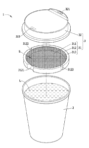
has
noticed that the beverage is too cold or too hot, he/she still has to sip the
beverage or
wait a long time until the temperature of the beverage rises or drops to a
temperature
suitable for drinking. If the waiting time is too long, the temperature of the
beverage
will change too much, so the drinker may not enjoy the beverage of the desired
temperature. This is very inconvenient.
[0004] Furthermore, when using the eco-friendly container, if
the user carries it
carelessly or the container receives a collision, the liquid in the container
may be
spilled, which will not only cause waste, but also cause inconvenience to the
drinker.
[0005] Therefore, it is an important subject to provide a
portable container and a lid
structure thereof that can adjust the temperature and flavor of the beverage
in the
container based on the design of the lid structure, so that the drinker can
enjoy the
beverage of different flavors with a proper temperature, thereby enhancing the
convenience in drinking. In addition, the lid structure can provide a snack so
as to
increase the fun of drinking. Moreover, based on the design of the lid
structure, the
structure of the portable container can be strengthened so as to prevent
liquid from
leaking out and make it easy to carry.
SUMMARY
100061 An objective of this disclosure is to provide a portable
container and a lid
structure thereof Compared to the conventional art, due to the design of the
lid
structure of this disclosure, a part of the beverage can be retained in the
lid structure
according to personal preference, and the flavor and temperature of the
beverage in
the container can be adjusted by the period of retention time. Thus, the
drinker can
2
CA 03141280 2021-12-9
drink different flavor beverages with the appropriate temperature by sips or
batches,
and this can increase the convenience and fun of drinking. In addition, a part
of the
lid structure is edible, and the drinker can directly take it as a snack after
drinking,
which can add the fun to drinking. Moreover, the lid structure can be used to
strengthen the structure of the portable container, prevent liquid from
spilling out, and
make it easier to carry.
[0007]
To achieve the above objective, this disclosure provides a lid structure of a
portable container, which comprises an edible first part. The first part
comprises a
bottom portion and an annular wall. The annular wall extends from a periphery
of
the bottom portion in a direction having an included angle with the bottom
portion.
The bottom portion and the annular wall form an accommodating space. An outer
periphery of the annular wall is configured with at least one first opening.
[0008] In one embodiment, the first part further comprises at least one edible
and
soluble flavor portion, and the at least one flavor portion is provided on at
least a part
of an inner surface of the bottom portion and/or the annular wall facing the
accommodating space.
[0009] In one embodiment, the first part further comprises at least one recess
portion, the at least one recess portion is formed on the inner surface of the
bottom
portion and/or the annular wall facing the accommodating space, and the at
least one
flavor portion is disposed in the recess portion.
100101 In one embodiment, the first part further comprises a groove configured
on
at least a part of the outer periphery of the annular wall away from the
accommodating space and the bottom portion.
[0011] In one embodiment, the first part further comprises a partition
portion, the
3
CA 03141280 2021-12-9
partition portion is configured on the inner surface of the bottom portion
facing the
accommodating space, and two ends of the partition portion connect to the
annular
wall for separating the accommodating space into a first accommodating space
and a
second accommodating space.
[0012] In one embodiment, the first part comprises at least two flavor
portions, and
the at least two flavor portions are arranged in the first accommodating space
and the
second accommodating space, respectively.
[0013] In one embodiment, the outer periphery of the annular wall is
configured
with a first opening, and the first opening is arranged corresponding to the
partition
portion; or the outer periphery of the annular wall is configured with two
first
openings, and the first openings are arranged corresponding to the first
accommodating space and the second accommodating space, respectively.
100141 In one embodiment, the outer periphery of the annular wall comprises at
least one second opening.
[0015] In one embodiment, the lid structure further comprises a second part.
The
second part has a third opening, and the second part covers the first part.
The
accommodating space opens toward the second part. The at least one first
opening
and the third opening are located at opposite sides of the bottom portion,
respectively.
[0016] To achieve the above objective, the present disclosure
also provides a
portable container, which comprises a containing portion and the above-
mentioned lid
structure. The first part covers an inner periphery of the containing portion
close to a
rim of the containing portion, and the second part covers an outer periphery
of the
rim.
[0017] To achieve the above objective, the present disclosure
also provides a
4
CA 03141280 2021-12-9
portable container, which comprises a containing portion and the above-
mentioned lid
structure. The first part is connected to an inner surface of the second part,
and the
second part covers the outer periphery of the rim of the containing portion.
[0018]
As mentioned above, due to the design of the lid structure of this disclosure,
a part of the beverage can be retained in the lid structure according to
personal
preference, and the flavor and temperature of the beverage in the container
can be
adjusted by the period of retention time. Thus, the drinker can drink
different flavor
beverages with the appropriate temperature by sips or batches, and this can
increase
the convenience and fun of drinking. In addition, a part of the lid structure
is edible,
and the drinker can directly take it as a snack after drinking, which can add
the fun to
drinking. Moreover, the lid structure can be used to strengthen the structure
of the
portable container, prevent liquid from spilling out, and make it easier to
carry.
BRIEF DESCRIPTION OF THE DRAWINGS
[0019] FIG. IA is a schematic diagram showing a portable container according
to a
first embodiment of this disclosure, wherein the lid structure is applied to
the
containing portion.
[0020] FIG. 1B is an exploded view of the lid structure and the containing
portion
of the portable container of FIG. IA.
[0021] FIG. 1C is a sectional view of the assembled portable container of FIG.
IA.
[0022] FIG. 1D to FIG. lE are schematic diagram showing the continuous
operations in drinking status of the portable container of FIG. 1C.
[0023] FIG. IF to FIG. II are schematic diagrams showing other aspects of the
lid
structure of the portable container of FIG. 1B.
[0024] FIG. 2A is a schematic diagram showing a portable container according
to a
CA 03141280 2021-12-9
second embodiment of this disclosure, wherein the lid structure is applied to
the
containing portion.
[0025] FIG. 2B is an exploded view of the lid structure and the containing
portion
of the portable container of FIG. 2A.
[0026] FIG. 2C is a sectional view of the assembled portable container of FIG.
2A.
[0027] FIG. 3A is a schematic diagram showing a portable container according
to a
third embodiment of this disclosure, wherein the lid structure is applied to
the
containing portion.
[0028] FIG. 3B is a sectional view of the assembled portable container of FIG.
3A.
[0029] FIG. 4A is a schematic diagram showing a portable container according
to a
fourth embodiment of this disclosure, wherein the lid structure is applied to
the
containing portion.
[0030] FIG. 4B is a sectional view of the assembled portable container of FIG.
4A.
[0031] FIG. 4C is a sectional view showing another aspect of the portable
container
of FIG. 4A.
[0032] FIG. 5A is a schematic diagram showing a portable container according
to a
fifth embodiment of this disclosure, wherein the lid structure is applied to
the
containing portion.
[0033] FIG. 5B is a perspective schematic view of the assembled portable
container
of FIG. 5A.
[0034] FIG. 5C to FIG. 5D are schematic diagram showing the continuous
operations in drinking status of the portable container of FIG. 5B.
[0035] FIG. 5E is a schematic diagram showing another drinking status of the
6
CA 03141280 2021-12-9
portable container of FIG. 5B.
[0036] FIG. 6A is a schematic diagram showing a portable container according
to a
sixth embodiment of this disclosure, wherein the lid structure is applied to
the
containing portion.
[0037] FIG. 6B is a perspective schematic view of the assembled portable
container
of FIG. 6A.
[0038] FIG. 6C to FIG. 6D are schematic diagram showing different drinking
statuses of the portable container of FIG. 6B.
[0039] FIG. 7A is a schematic diagram showing a portable container according
to a
seventh embodiment of this disclosure, wherein the lid structure is applied to
the
containing portion.
[0040] FIG. 7B is a sectional view of the assembled portable container of FIG.
7A.
[0041] FIG. 8A is a schematic diagram showing a portable container according
to
an eighth embodiment of this disclosure, wherein the lid structure is applied
to the
containing portion.
[0042] FIG. 8B is a sectional view of the assembled portable container of FIG.
8A.
DETAILED DESCRIPTION OF THE DISCLOSURE
[0043] Hereinafter, the preferred embodiments of the portable container and
the lid
structure according to the present disclosure will be described with reference
to the
relevant drawings, wherein the same components will be described with the same
reference numbers.
[0044]
The portable container and the lid structure of this disclosure can, based on
the design of the lid structure, retain a part of the beverage in the lid
structure
7
CA 03141280 2021-12-9
according to personal preference, and the flavor and temperature of the
beverage in
the container can be adjusted by the period of retention time. Thus, the
drinker can
drink different flavor beverages with the appropriate temperature by sips or
batches,
and this can increase the convenience and fun of drinking. In addition, a part
of the
lid structure is edible, and the drinker can directly take it as a snack after
drinking,
which can add the fun to drinking. Moreover, the lid structure can be used to
strengthen the structure of the portable container, prevent liquid from
spilling out, and
make it easier to carry.
[0045] Please refer to FIGS. IA and 1B, wherein FIG. IA is a schematic diagram
showing a portable container according to a first embodiment of this
disclosure, where
the lid structure is applied to the containing portion, and FIG. 1B is an
exploded view
of the lid structure and the containing portion of the portable container of
FIG. 1A.
As shown in FIG. 1A, the portable container 1 of this disclosure comprises a
containing portion 2 and a lid structure 3. The lid structure 3 comprises an
edible
first part 31. The lid structure 3 further comprises a second part 32, which
covers the
first part 31.
[0046]
Please refer to FIG. IC, wherein FIG. IC is a sectional view of the
assembled portable container of FIG. 1A. The first part 31 can cover an inner
periphery of the containing portion 2 close to a rim of the containing portion
2, and
the second part 32 can cover an outer periphery of the rim. The portable
container
can be, for example but not limited to, an eco-friendly container (including
the
disposable container or the reusable container).
[0047] Please refer to FIGS. lA to IC and FIG. 11, wherein FIG. 11 is a
schematic
diagram showing another aspect of the lid structure of the portable container
of FIG.
1B. In this embodiment, the first part 31 comprises a bottom portion 311 and
an
CA 03141280 2021-12-9
annular wall 312. The annular wall 312 extends from a periphery of the bottom
portion 311 in a direction D2 having an included angle 0 with the bottom
portion 311.
The bottom portion 311 and the annular wall 312 form an accommodating space S.
An outer periphery of the annular wall 312 is configured with at least one
first
opening 3121. As shown in FIG. 1B, the outer periphery of the annular wall 312
is
formed with a first opening 3121, wherein the thickness of the part of the
annular wall
312 formed with the first opening 3121 is thinner than the thickness of the
part of the
annular wall 312 not formed with the first opening 3121. That is, the first
opening
3121 is formed by cutting off a part of the annular wall 312. Alternatively,
as shown
in FIG. II, the outer periphery of the annular wall 312' of the first part 31'
is
configured with a first opening 3121a, and the entire annular wall 312' has a
uniform
thickness. That is, the first opening 3121a is formed by curving a part of the
annular
wall 312' toward the accommodating space S. In addition, as shown in FIG. 1C,
the
bottom portion extends in a direction D1, and the annular wall 312 extends
from a
periphery of the bottom portion 311 in a direction D2 having an included angle
0 with
the direction Dl. The bottom portion 311 and the annular wall 312 form an
accommodating space S, and the accommodating space S opens toward the second
part 32. In particular, FIG. IC shows that the included angle 0 is 90 degrees.
However, the included angle 0 can be, for example but not limited to, 45
degrees, 60
degrees, 70 degrees, 80 degrees, or any value that allows the bottom portion
311 and
the annular wall 312 to form the accommodating space S, and this disclosure is
not
limited thereto. In addition, FIG. 1B shows that the outer periphery of the
annular
wall 312 is formed with one first opening 3121. However, the number and
arrangement of the first opening(s) 3121 can be changed based on the
requirement of
users. Any configuration that can prevent the situation that the first opening
3121
penetrates from the outer periphery of the annular wall 312 to the inner
surface
9
CA 03141280 2021-12-9
thereof, and thus ensure that the accommodating space S formed by the annular
wall
312 and the bottom portion 311 can have the function of holding the liquid L
is
acceptable, and this disclosure is not limited. Moreover, the figures show
that the
upper edge of the annular wall 312 is a circular wall. However, the upper edge
of
the annular wall 312 can also be a quadrilateral, triangular or polygonal
wall, or any
shape that allows the annular wall 312 and the bottom portion 311 to form the
accommodating space S and allows the first part 31 to cover the inner
periphery of the
containing portion 2 close to the rim of the containing portion 2. This
disclosure is
not limited.
[0048] Referring to FIGS. IA to IC and FIG. 11, in this embodiment, the outer
periphery of the annular wall 312 of the first part 31 comprises at least one
second
opening 3122, the second part 32 has a third opening 321, and the at least one
first
opening 3121 and the third opening 321 are located at opposite sides of the
bottom
portion 311, respectively. The functions of the first opening 3121, the second
opening 3122 and the third opening 321 will be described hereinafter, and the
details
thereof are not described here. For example, as shown in FIG. 1B, the outer
periphery of the annular wall 312 is formed with two second openings 3122,
wherein
the thicknesses of the parts of the annular wall 312 formed with the second
openings
3122 are thinner than the thickness of the part of the annular wall 312 not
formed with
the second opening 3122. That is, each second opening 3122 is formed by
cutting
off a part of the annular wall 312. Alternatively, as shown in FIG. II, the
outer
periphery of the annular wall 312' of the first part 31' is configured with
two second
openings 3122', and the entire annular wall 312' has a uniform thickness. That
is,
each second opening 3122' is formed by curving a part of the annular wall 312'
toward the accommodating space S. In addition, FIG. 1B shows that the outer
CA 03141280 2021-12-9
periphery of the annular wall 312 is formed with two second openings 3122.
However, the number and arrangement of the second openings 3122 can be changed
based on the requirement of users. Any configuration that can prevent the
situation
that the second opening 3 122 penetrates from the outer periphery of the
annular wall
312 to the inner surface thereof, and thus ensure that the accommodating space
S
formed by the annular wall 312 and the bottom portion 311 can have the
function of
holding the liquid L is acceptable, and this disclosure is not limited.
10049] Please refer to FIG. 1B and FIGS. 1F to 1H, wherein FIGS. 1F to 111 are
schematic diagrams showing other aspects of the lid structure of the portable
container of FIG. 1B. In this embodiment, the first part 31 further comprises
at least
one edible and soluble flavor portion 313, and the at least one flavor portion
313 is
provided on at least a part of an inner surface of the bottom portion 311
andlor the
annular wall 312 facing the accommodating space S. For the sake of ease of
description, the flavor portion 313 is represented by dots pattern. Although
FIG. 1B
shows that the flavor portion 313 of the first part 31 is provided on the
entire inner
surface of the bottom portion 311 and the annular wall 312 facing the
accommodating
space 5, the flavor portion 313a of the first part 31a as shown in FIG. 1F is
provided
only on the inner surface of the annular wall 312 facing the accommodating
space S;
or the flavor portion 313b of the first part 3 lb as shown in FIG. 1G is
provided only
on the inner surface of the bottom portion 311 facing the accommodating space
5: or
the flavor portion 313c of the first part 31c as shown in FIG. 1H is provided
only on a
part of the inner surface of the bottom portion 311 and the annular wall 312
facing the
accommodating space S. This disclosure is not limited thereto. The flavor
portion
313, 313a, 313b or 313c can be selected from easily soluble biscuits,
meringue,
fondant, flavored ice cubes, liquid flavor packets, solid flavor packets,
powder flavor
11
CA 03141280 2021-12-9
packets, or a combination thereof The flavor portions 313, 313a, 313b, and
313c
can be provided on at least a part of the inner surfaces of the bottom portion
311
and/or the annular wall 312 facing the accommodating space S by baking,
spraying,
coating, printing, screen printing, placing, embedding, or sticking. For
example, the
edible and soluble flavor portions 313, 313a, 313b and 313c can be used to
increase
the flavor of the liquid L (liquid L is shown by the horizontal dashed line in
the figure)
when the drinker drinks. In addition, although FIG. 1H shows that the flavor
portion
313c of the first part 31c is only provided on a part of the inner surface of
the bottom
portion 311 and the annular wall 312 facing the accommodating space S and has
a
stripe shape, the flavor portion 313c can also be provided in a special
pattern such as,
for example but not limited to, a text, latte art, flower, animal or cartoon
character,
which can be used in conjunction with a transparent second part 32 for
increasing the
visual interest while adjusting the flavor and temperature of the beverage.
100501
The operations of utilizing the flavor portion to increase the flavor of the
contained liquid in the portable container will be described hereinafter with
reference
to FIGS. 1C to 1E. FIG. ID to FIG. lE are schematic diagram showing the
continuous operations in drinking status of the portable container of FIG. 1C.
When
the user wants to add the flavor of the flavor portion 313 to the liquid L in
the
container, the portable container 1 should first be tilted toward the first
opening 3121
for a few seconds to allow the liquid L to flow into the accommodating space S
(as
shown in FIG. 1D). Then, the portable container can be returned to the stand-
up
position. At this time, the excess liquid L will flow from the second openings
3122
(referring to FIG. 1B, while the sectional views of FIGS. 1C to 1E do not show
the
second openings 3122) back to the inside of the containing portion 2. Since
the
flavor portion 313 is edible and soluble, after the liquid L flows into the
12
CA 03141280 2021-12-9
accommodating space S, it will contact the flavor portion 313, so that the
flavor
portion 313 can be dissolved in the liquid L. Accordingly, the liquid L will
be added
with the flavor of the flavor portion 313. After that, the portable container
1 is
directly tilted toward the third opening 321 (as shown in FIG. 1E), and the
user can
drink the liquid L added with the flavor of the flavor portion 313. For
example, as
shown in FIG. 1C, the liquid L is hot coffee, and the flavor portion 313 is
chocolate,
which can be arranged on the inner surface of the bottom portion 311 and the
annular
wall 312 facing the accommodating space S by spraying, coating or sticking.
The
user can proceed the continuous operations with the portable container in
drinking
status so as to make the hot coffee enter the accommodating space S of the
first part
31 from the first opening 3121, and then shake the container or adjust the
period of
remaining the hot coffee in the accommodating space S based on personal taste.
Accordingly, the chocolate is dissolved in the hot coffee, and then the hot
coffee with
a chocolate flavor (also called mocha coffee) can be provided from the third
opening
321 of the second part 32. Here, although the liquid L is hot coffee and the
flavor
portion 313 is chocolate as an example for illustration, the liquid L can be
cold or hot
drink such as, for example but not limited to, water, coffee, milk, black tea,
green tea,
milk tea or any of other drinks. The flavor portion 313 can be, for example
but not
limited to, cinnamon, cardamom, hazelnut, vanilla powder, vanilla block,
chocolate
powder, brandy, lemon peel, orange peel, coconut milk, coconut milk, coconut
oil,
cream, birch mushroom, ganoderma, cordyceps, banana, blue-green seaweed, agave
ginger syrup, turmeric powder, rosemary, honey, brown sugar, etc., or any of
other
materials with flavor function, or that material that can be added to beverage
made of
easily soluble biscuits, meringue, fondant, flavored ice cubes, liquid flavor
packets,
solid flavor packets, powder flavor packets or any of other easy-to-dissolve
flavor
combinations, and this disclosure is not limited thereto. The above-mentioned
easily
13
CA 03141280 2021-12-9
soluble biscuits, meringue, fondant, flavored ice cubes, liquid flavor
packets, solid
flavor packets, powder flavor packets, or a combination thereof can be
provided on at
least a part of the inner surfaces of the bottom portion 311 and/or the
annular wall 312
facing the accommodating space S by baking, spraying, coating, printing,
screen
printing, placing, embedding, or sticking, and this disclosure is not limited
thereto.
That is, the type of liquid, the flavor and material of the flavor portion,
the manner
and range of arranging the flavor portion on at least a part of the inner
surface of the
bottom portion 311 and/or the annular wall 312 facing the accommodating space
S
can be made according to the needs of the user, and this disclosure is not
limited
thereto.
100511
Referring to FIGS. 1C to 1E, in this embodiment, the first part 31 is an
artificial edible starch body, such as, for example but not limited to, baked
hard
biscuits or dentifrice. In details, the artificial edible starch body of the
first part 31 is
not easy soluble, and the flavor part 313 of the first part 31 is soluble
(easy soluble).
Therethre, when the liquid L enters the accommodating space S of the first
part 31
through the first opening 3121 of the first part 31, the flavor portion 313
can be
dissolved in the liquid L (while retaining the edible starch body), and the
user can
drink the flavored liquid L containing the flavor portion 313 from the third
opening
321 of the second part 32. After the user finishes the beverage, he/she can
take the
first part 31 (the edible starch body) to eat directly. This not only can
enjoy different
flavored beverages, but also can enjoy flavored biscuits soaked in a drink so
as to add
fun. Particularly, the first part 31 not only comprises the flavor portion 313
to add
flavor to the liquid L and can also be directly ate, but also has the function
of
maintaining and adjusting the temperature of the liquid L. When the liquid L
enters
the accommodating space S of the first part 31 from the opening 3121 of the
first part
14
CA 03141280 2021-12-9
31, a part of the liquid L can be allowed to stay in the accommodating space S
to
isolate it from the most part of liquid L in the containing portion 2, thereby
adjusting
the temperature of the liquid L in the accommodation space S and maintaining
the
temperature of the liquid L in the accommodation space S by isolating the most
part
of liquid L in the containing portion 2 from the outside. In addition, the
flavor of the
flavor portion 313 can be added to the liquid L in the accommodating space S,
and the
user can drink from the third opening 321 of the second part 32 to enjoy the
temperature-appropriate liquid L with the flavor of the flavor portion 313
(neither too
hot nor too cold).
[0052] Referring to FIGS. 1C to lE again, in this embodiment, the flavor
portion
313 can also be mixed with the edible starch of the first part 31 and then
made into an
artificial edible starch body. In other words, the flavor portion 313 can be
mixed
with the edible starch of the first part 31, and the flavor portion 313 and
the edible
starch of the first part 31 can together form an integrally formed single
component (an
edible starch body). When the liquid L enters the accommodating space S of the
first
part 31 from the first opening 3121 of the first part 31, the flavor portion
313 mixed in
the first part 31 can be dissolved in the liquid L (while retaining the edible
starch).
Then, the user can drink the liquid L with the flavor of the flavor portion
313 from the
third opening 321 of the second part 32. In particular, the edible starch
ingredients
such as, for example but not limited to, wheat flour (or flour), quinoa flour,
potato
starch, corn starch, sweet potato starch, glutinous rice flour, rice flour,
cassava flour,
lotus root flour or other edible starches well-known to skilled persons in the
art.
[0053] Please refer to FIGS. 2A to 2C, wherein FIG. 2A is a schematic diagram
showing a portable container according to a second embodiment of this
disclosure,
wherein the lid structure is applied to the containing portion. FIG. 2B is an
exploded
CA 03141280 2021-12-9
view of the lid structure and the containing portion of the portable container
of FIG.
2A, and FIG. 2C is a sectional view of the assembled portable container of
FIG. 2A.
The structure, components and functions of the portable container id of the
second
embodiment are mostly the same as those of the above-mentioned portable
container
1 of the first embodiment, so the detailed descriptions thereof will be
omitted. The
first embodiment and the second embodiment are different in the configuration
of the
first part of the lid structure. In the second embodiment, the first part 31d
of the lid
structure 3d further comprises at least one recess portion 314d. The at least
one
recess portion 314d is formed on the inner surface of the bottom portion 311d
and/or
the annular wall 312d facing the accommodating space S, and the al least one
flavor
portion 313d is disposed in the recess portion 314d. In particular, although
the
figures show that the first part 31d comprises one recess portion 314d and one
flavor
portion 313d, and the recess portion 314d is located at the center of the
bottom portion
311 d, however, the number of the recess portions 314d, the number of the
flavor
portions 313d and the positions thereof can be adjusted based on the
requirement of
user, and this disclosure is not limited thereto.
100541 Please refer to FIGS. 3A and 3B, wherein FIG. 3A is a schematic diagram
showing a portable container according to a third embodiment of this
disclosure,
wherein the lid structure is applied to the containing portion, and FIG. 3B is
a
sectional view of the assembled portable container of FIG. 3A. The structure,
components and functions of the portable container 1 e of the third embodiment
are
mostly the same as those of the above-mentioned portable container Id of the
second
embodiment, so the detailed descriptions thereof will be omitted. The third
embodiment and the second embodiment are different in the configuration of the
bottom portion of the first part of the lid structure. As shown in FIGS. 2A
and 2C,
16
CA 03141280 2021-12-9
the bottom portion 311d of the first part 31d of the lid structure 3d of the
second
embodiment has a uniform thickness. As shown in FIGS. 3A and 3B, the bottom
portion 311e of the first part 31e of the lid structure 3e of the third
embodiment has a
non-uniform thickness. The sectional view of the inner surface of the bottom
portion
311e has an arc-shape, and the thickness of the bottom portion 311e is
gradually
thinner as getting closer to the recess portion 314e. This design can collect
the liquid
L, which enters into the accommodating space S, at the center of the bottom
portion
311e (i.e., the recess portion 314e). In particular, although the figures show
that the
first part 31e comprises one recess portion 314c and one flavor portion 313e,
and the
recess portion 314e is located at the center of the bottom portion 311e,
however, the
number of the recess portions 314e, the number of the flavor portions 313e,
the
positions thereof, and the thickness of the bottom portion 311e can be
adjusted based
on the requirement of user, and this disclosure is not limited thereto.
[0055] Please refer to FIGS. 4A and 4B, wherein FIG. 4A is a schematic diagram
showing a portable container according to a fourth embodiment of this
disclosure,
wherein the lid structure is applied to the containing portion, and FIG. 4B is
a
sectional view of the assembled portable container of FIG. 4A. The structure,
components and functions of the portable container lf of the fourth embodiment
are
mostly the same as those of the above-mentioned portable container 1 of the
first
embodiment, so the detailed descriptions thereof will be omitted.
The first
embodiment and the fourth embodiment are different in the confiuuration of the
first
part of the lid structure. In this embodiment, the first part 31f of the lid
structure 3f
further comprises a groove 315f configured on at least a part of the outer
periphery of
the annular wall 312f away from the accommodating space S and the bottom
portion
311f. Specifically, as shown in FIG. 4B, based on this design of the groove
3151'
,
17
CA 03141280 2021-12-9
which is configured on at least a part of the outer periphery of the annular
wall 312f
away from the accommodating space S and the bottom portion 311f, when the
first
part 31f covers an inner periphery of the containing portion 2 close to a rim
of the
containing portion 2, it can be closer to the rim (the groove 315f of the
first part 31f is
higher than the rim). Accordingly, when the second part 32 covers an outer
periphery of the rim, it will not be interfered by the first part 31f, which
is disposed
higher than the rim, and may fail to cap the containing portion 2. Based on
this
design, the internal space of the containing portion 2 occupied by the first
part 31f can
be decreased, so that the capacity of the containing portion 2 for containing
the liquid
can be increased.
[0056] Please refer to FIG. 4C in view of FIG. 4B, wherein FIG. 4C is a
sectional
view showing another aspect of the portable container of FIG. 4A. The
structure,
components and functions of the portable container lf' are mostly the same as
those
of the above-mentioned portable container if, so the detailed descriptions
thereof will
be omitted. The portable container if' and the portable container if are
different in
the heights of the annular wall 312f' and the groove 315f' of the first part
of the lid
structure. In this embodiment, the first part 31f' of the lid structure 3f'
further
comprises a groove 315f' configured on at least a part of the outer periphery
of the
annular wall 312f' away from the accommodating space S and the bottom portion
311f. Specifically, as shown in FIG. 4C, based on this design of the groove
315P,
which is configured on at least a part of the outer periphery of the annular
wall 312f'
away from the accommodating space S and the bottom portion 3111" , when the
first
part 3 if covers an inner periphery of the containing portion 2 close to a rim
of the
containing portion 2, it can be closer to the rim (the groove 315f' of the
first part 31f'
is higher than the rim). Accordingly, when the second part 32 covers an outer
18
CA 03141280 2021-12-9
periphery of the rim, it will not be interfered by the first part 31f', which
is disposed
higher than the rim, and may fail to cap the containing portion 2. In
addition, the
higher annular wall 312f' can increase the capacity of the accommodating space
S for
accommodating the liquid L, so that it is possible to adjust the flavor and
temperature
of a larger amount of liquid L, thereby increasing the convenience of
drinking.
[0057] Please refer to FIGS. 5A to 5B, wherein FIG. 5A is a schematic diagram
showing a portable container according to a fifth embodiment of this
disclosure,
wherein the lid structure is applied to the containing portion, and FIG. 5B is
a
perspective schematic view of the assembled portable container of FIG. 5A. The
structure, components and functions of the portable container 1 a of the fifth
embodiment are mostly the same as those of the above-mentioned portable
container
1 of the first embodiment, so the detailed descriptions thereof will be
omitted. The
first embodiment and the fifth embodiment are different in the configuration
of the
first part of the lid structure. In this embodiment, the first part 31g of the
lid
structure 3g further comprises a partition portion 316g. The partition portion
316g is
configured on the inner surface of the bottom portion 311g facing the
accommodating
space 5, and two ends of the partition portion 316g connect to the annular
wall 3] 2g
for separating the accommodating space S into a first accommodating space Si
and a
second accommodating space 52. In this embodiment, the first part lg comprises
at
least two flavor portions 313g and 313a', and the at least two flavor portions
313g and
313g' are arranged in the first accommodating space Si and the second
accommodating space S2, respectively. In this embodiment, the outer periphery
of
the annular wall 312a is configured with a first opening 3121, and the first
opening
3121 is arranged corresponding to the partition portion 316g. As shown in the
figure,
the first opening 3121 is arranged corresponding to one end of the partition
portion
19
CA 03141280 2021-12-9
316g and also corresponding to both of the first accommodating space SI and
the
second accommodating space S2.
[0058]
The operations of utilizing the flavor portion to increase the flavor of the
contained liquid in the portable container will be described hereinafter with
reference
to FIGS. 5C to 5E. FIG. 5C to FIG. 5D are schematic diagram showing the
continuous operations in drinking status of the portable container of FIG. 5B,
and FIG.
5E is a schematic diagram showing another drinking status of the portable
container
of FIG. 5B. For example, when the user wants to add the flavor of the flavor
portion
313g to the liquid L in the container, the portable container Ig should first
be tilted
toward the first opening 3121 and the first accommodating space Si (see the
arrow
direction D3 of FIG. 5C) for a few seconds to allow the liquid L to flow into
the first
accommodating space Si (as shown in FIG. 5C). Then, the portable container can
be returned to the stand-up position. At this time, the excess liquid L will
flow from
the second openings 3122 back to the inside of the container portion 2. Since
the
flavor portion 313g is edible and soluble, after the liquid L flows into the
first
accommodating space Si (as shown in FIG. 5D), it will contact the flavor
portion
313g, so that the flavor portion 313g can be dissolved in the liquid L.
Accordingly,
the liquid L will be added with the flavor of the flavor portion 313g. After
that, the
portable container 1 g is directly tilted toward the third opening 321, and
the user can
drink the liquid L added with the flavor of the flavor portion 313g.
Similarly, when
the user wants to add the flavor of the flavor portion 313g' to the liquid L
in the
container, the portable container 1g should first be tilted toward the first
opening 3121
and the second accommodating space S2 (not shown) for a few seconds to allow
the
liquid L to flow into the second accommodating space S2. Then, the portable
container can be returned to the stand-up position. At this time, the excess
liquid L
CA 03141280 2021-12-9
will flow from the second openings 3122 back to the inside of the container
portion 2.
Since the flavor portion 313g is edible and soluble, after the liquid L flows
into the
second accommodating space S2, it will contact the flavor portion 313g, so
that the
flavor portion 313g' can be dissolved in the liquid L. Accordingly, the liquid
L will
be added with the flavor of the flavor portion 313g. After that, the portable
container lg is directly tilted toward the third opening 321, and the user can
drink the
liquid L added with the flavor of the flavor portion 313g'. In addition, when
the user
wants to add both of the flavors of the flavor portions 313g and 313g' to the
liquid L
in the container, the portable container 1g should first be tilted toward the
first
opening 3121 (not shown) for a few seconds to allow the liquid L to flow into
the first
accommodating space Si and the second accommodating space S2. Then, the
portable container can be returned to the stand-up position (As shown in FIG.
5E).
At this time, the excess liquid L will flow from the second openings 3122 back
to the
inside of the container portion 2. Since the flavor portions 313g and 313g'
are edible
and soluble, after the liquid L flows into the first accommodating space Si
and the
second accommodating space S2, it will contact the flavor portions 313g and
313g',
so that the flavor portions 313g and 313g' can be dissolved in the liquid L.
Accordingly, the liquid L will be added with both flavors of the flavor
portions 313g
and 313g'. After that, the portable container 1 g is directly tilted toward
the third
opening 321, and the user can drink the liquid L added with the flavors of the
flavor
portions 313g and 313g. For example, as shown in FIG. 5B, the liquid L is hot
coffee, the flavor portion 313g is chocolate, and the flavor portion 313g' is
milk,
wherein the chocolate and milk can be arranged on the inner surface of the
bottom
portion 311g and the annular wall 312g facing the first accommodating space Si
and
the second accommodating space S2 by spraying, coating, printing, screen
printing,
placing, embedding, or sticking. The user can proceed the continuous
operations
21
CA 03141280 2021-12-9
with the portable container in drinking status so as to make the hot coffee
enter the
first accommodating space Si and/or the second accommodating space S2 of the
first
part 31g from the first opening 3121 so as the dissolve the chocolate and/or
milk into
the hot coffee. Accordingly, the hot coffee with a chocolate and/or milk
flavor
(chocolate coffee, latte or chocolate latte, also known as mocha flavored
coffee) can
be provided from the third opening 321 of the second part 32.
[0059] Please refer to FIGS. 6A to 6B, wherein FIG. 6A is a schematic diagram
showing a portable container according to a sixth embodiment of this
disclosure,
wherein the lid structure is applied to the containing portion, and FIG. 6B is
a
perspective schematic view of the assembled portable container of FIG. 6A. The
structure, components and functions of the portable container lb of the sixth
embodiment are mostly the same as those of the above-mentioned portable
container
lg of the fifth embodiment, so the detailed descriptions thereof will be
omitted. The
sixth embodiment and the fifth embodiment are different in the configuration
of the
first opening of the first part of the lid structure. In this embodiment, the
outer
periphery of the annular wall 312h comprises two first openings 3121 and
3121',
which are arranged corresponding the first accommodating space Si and the
second
accommodating space S2, respectively. Each of the first openings 3121 and
3121' is
disposed close to one end of the partition portion 316h.
[0060] Please refer to FIGS. 6C to 6D, wherein FIG. 6C to FIG. 6D are
schematic
diagram showing different drinking statuses of the portable container of FIG.
6B.
For example, when the user wants to add the flavor of the flavor portion 313h
to the
liquid L in the container, the portable container lh should first be tilted
toward the
first opening 3121 and the first accommodating space Si for a few seconds to
allow
the liquid L to flow into the first accommodating space Si (as shown in FIG.
6C).
22
CA 03141280 2021-12-9
Then, the portable container can be returned to the stand-up position. At this
time,
the excess liquid L will flow from the second openings 3122 back to the inside
of the
container portion 2. Since the flavor portion 313h is edible and soluble,
after the
liquid L flows into the first accommodating space Si (as shown in FIG. 6C), it
will
contact the flavor portion 313h, so that the flavor portion 313h can be
dissolved in the
liquid L. Accordingly, the liquid L will be added with the flavor of the
flavor portion
313h. After that, the portable container lb is directly tilted toward the
third opening
321, and the user can drink the liquid L added with the flavor of the flavor
portion
313h. Similarly, when the user wants to add the flavor of the flavor portion
313h' to
the liquid L in the container, the portable container lh should first be
tilted toward the
first opening 3121' and the second accommodating space S2 (not shown) for a
few
seconds to allow the liquid L to flow into the second accommodating space S2.
Then, the portable container can be returned to the stand-up position. At this
time,
the excess liquid L will flow from the second openings 3122 back to the inside
of the
container portion 2. Since the flavor portion 313h is edible and soluble,
after the
liquid L flows into the second accommodating space S2, it will contact the
flavor
portion 313h', so that the flavor portion 313h' can be dissolved in the liquid
L.
Accordingly, the liquid L will be added with the flavor of the flavor portion
313h'.
After that, the portable container lb is directly tilted toward the third
opening 321,
and the user can drink the liquid L added with the flavor of the flavor
portion 313h'.
In addition, when the user wants to add both of the flavors of the flavor
portions 313h
and 313h' to the liquid L in the container, the portable container lb should
first be
tilted toward the first openings 3121 and 3121' (not shown) for a few seconds
to allow
the liquid L to flow into the first accommodating space SI and the second
accommodating space S2. Then, the portable container can be returned to the
stand-up position (As shown in FIG. 6D). At this time, the excess liquid L
will flow
23
CA 03141280 2021-12-9
from the second openings 3122 back to the inside of the container portion 2.
Since
the flavor portions 313h and 313h' are edible and soluble, after the liquid L
flows into
the first accommodating space S1 and the second accommodating space 52, it
will
contact the flavor portions 313h and 313h', so that the flavor portions 313h
and 313h'
can be dissolved in the liquid L. Accordingly, the liquid L will be added with
both
flavors of the flavor portions 313h and 313h'. After that, the portable
container lh is
directly tilted toward the third opening 321, and the user can drink the
liquid L added
with the flavors of the flavor portions 313h and 313h'. Compared to the fifth
embodiment, this embodiment has a design of two first openings 3121 and 3121',
so
that it is easier to control the liquid to flow into the first accommodating
space Si
only or into the second accommodating space S2 only.
[0061] Please refer to FIGS. 7A to 7B, wherein FIG. 7A is a schematic diagram
showing a portable container according to a seventh embodiment of this
disclosure,
wherein the lid structure is applied to the containing portion, and FIG. 7B is
a
sectional view of the assembled portable container of FIG. 7A. The structure,
components and functions of the portable container li of the seventh
embodiment are
mostly the same as those of the above-mentioned portable container lh of the
sixth
embodiment, so the detailed descriptions thereof will be omitted. The seventh
embodiment and the sixth embodiment are different in the positions of the
first
opening of the first part of the lid structure. In this embodiment, the outer
periphery
of the annular wall 312i comprises two first openings 3121 and 3121', which
are
arranged corresponding the first accommodating space S1 and the second
accommodating space S2, respectively. The first openings 3121 and 3121' are
arranged away from the partition portion 316i (as shown in FIG. 7A).
Particularly,
in this embodiment, the first openings 3121 and 3121' are configured to allow
the
24
CA 03141280 2021-12-9
liquid L to follow from the containing portion 2 to the first accommodating
space Si
and/or the second accommodating space 52. Moreover, if the first accommodating
space Si and/or the second accommodating space S2 contains excess liquid L,
the
excess part can flow back the inside of the containing portion 2 through the
first
openings 3121 and 3121'.
[0062]
Referring to FIG. 7B, in this embodiment, the first part 31i of the portable
container li can further comprise an edible gel layer 318i, wherein the edible
gel layer
318i is disposed on a surface of the first part 31i facing the containing
portion 2, or on
a part of the surface of the first part 31i other than the first accommodating
space Si
and the second accommodating space S2. The edible gel layer 318i is configured
to
prevent the first part 31i from being softened due to contact with the liquid
L for too
long. In particular, any of the first parts 31, 31', 31a, 31b, 31c, 31d, 31e,
31f, 31f,
31g and 31h in the above-mentioned embodiments may also include an edible gel
layer. The edible gum layer can be made of animal gum, vegetable gum or
microbial
gum, and the ingredient can be, for example but not limited to, seaweed gum,
acacia
gum, glutinous rice gum, apple gum, corn syrup gum, xanthan gum, Gellan gum,
gelatin, and shellac, or any of other edible gum ingredients known to those
skilled in
the art.
[0063] Please refer to FIGS. 8A to 8B, wherein FIG. 8A is a schematic diagram
showing a portable container according to an eighth embodiment of this
disclosure,
wherein the lid structure is applied to the containing portion, and FIG. 8B is
a
sectional view of the assembled portable container of FIG. 8A. The structure,
components and functions of the portable container lj of the eighth embodiment
are
mostly the same as those of the above-mentioned portable containers 1, id, le,
if', lg,
lh and li of the above-mentioned embodiments, so the detailed descriptions
thereof
CA 03141280 2021-12-9
will be omitted. The eighth embodiment and the previous embodiments are
different
in the configuration of the lid structure. In the previous embodiments, the
first part
31, 31', 31a, 31b, 31c, 31d, 31e, 31f, 31f', 31g, 31h or 31i covers on the
inner
periphery of the containing portion 2 close to the rim of the containing
portion 2, and
then the second part 32 covers on the outer periphery of the rim. In this
embodiment,
the portable container lj comprises a containing portion 2 and a lid structure
3j. The
first part 31j connects to the inner surface of the second part 32j, and then
the second
part 32j covers the outer periphery of the containing portion 2 close to the
rim of the
containing portion 2. For example, the first part 31j has an engaging
structure 317j,
and the second part 32j has a fastening structure 322j. The engaging structure
317j
and the fastening structure 322j can be engaged with each other so as to
connect the
first part 31 j to the inner surface of the second part 32j. Afterwards, the
second part
32j is capped on the outer periphery of the rim. In particular, although FIGS.
8A and
8B show that the first part 31j and the second part 32j are connected by the
engagement of the first part 31j and the second part 32j, the first part 31j
and the
second part 32j can be connected by any of other methods such as hooking,
screwing,
embedding, riveting, adhering or the like, and this disclosure is not limited.
In
addition, when the first part 31, 31', 31a, 31b, 31c, 31d, 31e, 31f, 31f',
31g, 31h or
31i is configured corresponding to the containing portion 2, the structural
strength of
the rim of the containing portion 2 can be enhanced. This configuration can
prevent
the deformation of the containing portion 2 when the portable container 1, ld,
le, lf,
1r, lg, lh, li or lj is pressed during transportation, wherein the liquid L
may leak
from the rim once the containing portion 2 is deformed. In addition, the rim
of the
portable container 1, Id, le, if, If', lg, lh, li or lj is provided with the
first part 31,
31', 31a, 31b, 31e, 31d, 31e, 31f, 31f', 31g, 31h or 31i, and the second part
32 or 32j.
This configuration can isolate the liquid L inside the containing portion 2
from the
26
CA 03141280 2021-12-9
external environment, thereby remaining the temperature of the liquid L.
[0064] Referring to FIGS. I A to gR, each of the second parts 32 and 32j of
the
above-mentioned embodiments has a puncture portion 323, which is disposed
corresponding to the first opening 3121 (see FIG. 1A). In this embodiment, the
puncture portion 323 and the third opening 321 are disposed at the opposite
sides of
the second part 32 or 32j, and it can be fabricated by forming a semi-cut line
on the
second part 32 or 32j. The position of the puncture portion 323 can correspond
to
the first opening 3121. Accordingly, the user can directly press the puncture
portion
323 to form a complete opening, and then the liquid L in the containing
portion 2 can
be poured out through the puncture portion 323. Herein, the poured liquid L is
not
added with the flavor of the flavor portion 313, 313a, 313b, 313c, 313d, 313e,
313f,
313f', 313g, 313g', 313h, 313h' or 313j, so that the user can enjoy the
original flavor
of the liquid L. Besides, after the puncture portion 323 is pressed to form a
complete
opening, it can provide a ventilation function for balancing the pressures
inside and
outside the containing portion 2. Accordingly, the liquid L inside the
containing
portion 2 can be easily poured out through the third opening 321.
[0065] As mentioned above, due to the design of the lid
structure of this disclosure,
the flavor and temperature of the beverage in the container can be adjusted.
Thus,
the drinker can drink different flavor beverages with the appropriate
temperature by
sips or batches, and this can increase the convenience of drinking. In
addition, a part
of the lid structure is edible, and the drinker can directly take it as a
snack after
drinking, which can add the fun to drinking. Moreover, the lid structure can
be used
to strengthen the structure of the portable container, prevent liquid from
spilling out,
and make it easier to carry.
[0066] The above description is only illustrative and not
restrictive. Any
27
CA 03141280 2021-12-9
equivalent modifications or changes made to the present invention without
departing
from the spirit and scope of the present invention shall be included in the
scope of
Claims.
28
CA 03141280 2021-12-9