Language selection

Search

Patent 3141353 Summary

Third-party information liability

Some of the information on this Web page has been provided by external sources. The Government of Canada is not responsible for the accuracy, reliability or currency of the information supplied by external sources. Users wishing to rely upon this information should consult directly with the source of the information. Content provided by external sources is not subject to official languages, privacy and accessibility requirements.

Claims and Abstract availability

Any discrepancies in the text and image of the Claims and Abstract are due to differing posting times. Text of the Claims and Abstract are posted:

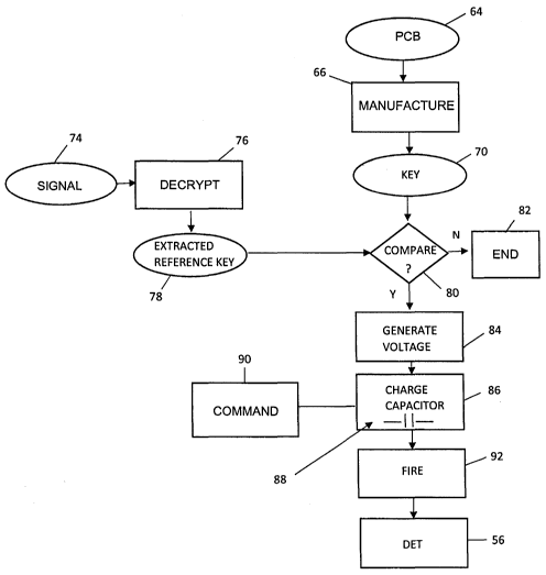
  • At the time the application is open to public inspection;
  • At the time of issue of the patent (grant).
(12) Patent Application: (11) CA 3141353
(54) English Title: WIRELESS DETONATOR ASSEMBLY
(54) French Title: ENSEMBLE DETONATEUR SANS FIL
Status: Pre-Grant
Bibliographic Data
(51) International Patent Classification (IPC):
  • F42D 1/05 (2006.01)
  • F42C 15/42 (2006.01)
(72) Inventors :
  • MEYER, TIELMAN CHRISTIAAN (South Africa)
  • MULLER, ELMAR LENNOX (South Africa)
  • LIEBENBERG, ABRAHAM JOHANNES (South Africa)
(73) Owners :
  • DETNET SOUTH AFRICA (PTY) LTD (South Africa)
(71) Applicants :
  • DETNET SOUTH AFRICA (PTY) LTD (South Africa)
(74) Agent: OYEN WIGGS GREEN & MUTALA LLP
(74) Associate agent:
(45) Issued:
(86) PCT Filing Date: 2021-02-02
(87) Open to Public Inspection: 2021-11-04
Examination requested: 2022-01-04
Availability of licence: N/A
(25) Language of filing: English

Patent Cooperation Treaty (PCT): Yes
(86) PCT Filing Number: PCT/ZA2021/050006
(87) International Publication Number: WO2021/222947
(85) National Entry: 2021-11-18

(30) Application Priority Data:
Application No. Country/Territory Date
NA/P/2020/0010 Namibia 2020-04-29

Abstracts

English Abstract

A wireless detonator assembly which includes a detonator, a receiver, a printed circuit board with a stored key which is hardwired onto the board during manufacture of the detonator assembly and control logic which allows the detonator to be fired only if the control logic extracts from a signal, received by the receiver, a reference key which is identical to the stored key.


French Abstract

L'invention concerne un ensemble détonateur sans fil qui comprend un détonateur, un récepteur, une carte de circuit imprimé avec une clé mémorisée qui est câblée sur la carte pendant la fabrication de l'ensemble détonateur et une logique de commande qui permet que le détonateur soit déclenché uniquement si la logique de commande extrait à partir d'un signal, reçu par le récepteur, une clé de référence qui est identique à la clé mémorisée.

Claims

Note: Claims are shown in the official language in which they were submitted.

CA 03141353 2021-11-18
WO 2021/222947
PCT/ZA2021/050006
6
CLAIMS
1. A wireless detonator assembly (16) which includes a receiver (38), a
memory unit (40),
a power source (44), control logic (42), a detonator (56) and explosive
material (52)
which is initiated, after receipt of an arm command, upon receipt by the
receiver (38) of
a fire command, wherein the memory unit (40) includes a printed circuit board
(64) with
a stored key (70) which is hardwired during manufacture of the receiver and
wherein
the control logic (42) allows initiation of the detonator (56) after receipt
of the fire
command if a received reference key (78), extracted from the arm command, is
the
same as the stored key (70).
2. A wireless detonator assembly (16) according to claim 1 wherein the
receiver (38) is
responsive to a signal sent from a control device (14) which includes one of
the following
in which the reference key is stored viz: a surface blast control unit (23);
an
underground blast control unit (24); and a near field communication card (26).
3. A wireless detonator assembly (10) according to claim 2 wherein the
control logic (42)
is operable to extract the reference key (78) from an encrypted signal (74)
which is
transmitted by the control device (14).
4. A wireless detonator assembly (10) which includes a detonator (56), a
receiver (38), a
printed circuit board (64) with a stored key (70) which is hardwired onto the
board during
manufacture of the detonator assembly and control logic (42) which allows the
detonator
(56) to be fired only if the control logic (42) extracts from a signal (74),
received by the
receiver (38), a reference key (78) which is identical to the stored key (70).

Description

Note: Descriptions are shown in the official language in which they were submitted.


CA 03141353 2021-11-18
WO 2021/222947
PCT/ZA2021/050006
1
WIRELESS DETONATOR ASSEMBLY
BACKGROUND OF THE INVENTION
[0001] This invention relates to a wireless detonator assembly.
[0002] A wireless detonator assembly installed in a borehole, once rendered
operative by
means of an arm command which is sent wirelessly, is initiated upon receipt of
a fire command,
also sent wirelessly. It is essential, as far as is possible, to eliminate the
possibility that initiation
can take place inadvertently e.g. due to receipt of a stray signal.
[0003] An object of the present invention is to address at least to some
extent the
aforementioned aspect.
SUMMARY OF THE INVENTION
[0004] The invention provides a wireless detonator assembly which includes a
receiver, a
memory unit, a power source, control logic, a detonator and explosive material
which is
initiated, after receipt of an arm command, upon receipt by the receiver of a
fire command,
wherein the memory unit includes a printed circuit board with a stored key
which is hardwired
during manufacture of the receiver and wherein the control logic allows
initiation of the
detonator after receipt of the fire command if a received reference key,
extracted from the arm
command, is the same as the stored key.
[0005] The arm command may be sent by a control device to the receiver.

CA 03141353 2021-11-18
WO 2021/222947
PCT/ZA2021/050006
2
[0006] If the received reference key equals the stored key then the control
logic, using energy
drawn from the power source, enables a fire voltage to be generated. As is
known in the art
the fire voltage may be used to charge a capacitor which, upon execution of
the fire command,
under the control of the control logic, is discharged to initiate the
detonator.
BRIEF DESCRIPTION OF THE DRAWINGS
[0007] The invention is further described by way of example with reference to
the
accompanying drawings wherein :
Figure 1 schematically illustrates aspects of a blasting system based on the
use of a wireless
detonator assembly according to the invention, and
Figure 2 illustrates a sequence of operations which is carried out when a
wireless detonator
assembly according to the invention is initiated.
DESCRIPTION OF PREFERRED EMBODIMENT
[0008] Figure 1 of the accompanying drawings illustrates a blast system 10
with a blast site
12, a control device 14, and a wireless detonator assembly 16 according to the
invention. The
.. detonator assembly 16 is one of a plurality of similar devices which are
deployed at the blast
site 12.
[0009] The blast site 12 includes a plurality of boreholes 20 which are formed
in a known
manner. Each borehole 20 is loaded with explosive 22 and at least one wireless
detonator
assembly 16.

CA 03141353 2021-11-18
WO 2021/222947
PCT/ZA2021/050006
3
[0010] The control device 14 includes at least one of the following, viz: a
surface blast control
unit 23, an underground blast control unit 24 and a near field communication
card 26. The
control device 14 further includes an encoder 28 and a transmitter 30.
[0011] The wireless detonator assembly 16 is typically used in an underground
location and,
in that event, the blast site 12 is a blast zone in an underground excavation.
Primary benefits
of using a wireless detonating arrangement are that there are no trailing
wires or conductors
leading to the detonators in the various boreholes, and generally the number
of personnel
required at the blast site is reduced. Thus there is enhanced reliability and
safety in operation.
[0012] The transmitter 30 can operate at a radio frequency or it can transmit
magnetic signals
through the ground. The transmitter 30 has an antenna 34 which is configured
accordingly.
These types of transmission techniques are known in the art and for this
reason are not further
described.
[0013] The wireless detonator assemblies 16 are substantially identical to one
another. Each
assembly 16 includes a first part 16A and a second part 16B. These parts are
interconnected
to one another at an assembly location, not shown, at the blast site 12¨ a
process which takes
place immediately before placement of the detonator assemblies into the
respective boreholes.
[0014] The first part 16A includes a housing 34 which contains or to which is
mounted an
antenna 36, a receiver 38, a memory unit 40, a logic module 42 and a power
supply 44.
[0015] The second part 16B includes a housing 50 into which is loaded an
explosive material
52.

CA 03141353 2021-11-18
WO 2021/222947
PCT/ZA2021/050006
4
[0016] When the first part 16A is connected to the second part 16B a detonator
56 is
connected to terminals on the logic module 42 and is exposed to the explosive
material 52. An
advantage of this technique is that the part 16A is separate from the
explosive 52, and the
detonator 56 is separated from the explosive 52. Thus the likelihood of
inadvertent initiation
taking place is negligible.
[0017] The receiver 38 includes a printed circuit board 64 (see Figure 2)
which, during
manufacture (66), is hardwired with a key 70. The key 70 may have any
appropriate length
and may be of any suitable format. In one example the key includes 32 bits. As
the key is set
during the manufacturing stage it cannot be altered after manufacture.
[0018] The key 70 which is hardwired into the printed circuit boards 64 of the
various receivers
38 is stored as a reference key in the control device 14 i.e. in the surface
blast control unit 23
or in the underground blast control unit 24 or otherwise is carried on a
proprietary near field
communication card 26. Any of these approaches can be used: the choice thereof
depends
on the system adopted at the blasting site.
[0019] When the detonator assemblies 16 at the blast site 12 are to be armed
the reference
key 70 which is available from one of the units 23 or 24 or from the NFC card
26 is encoded
by the encoder 28 and is then transmitted in a signal 74 via the transmitter
30 simultaneously
to the wireless detonator assemblies 16 in the various boreholes 20.
[0020] As is shown in Figure 2 the signal 74 transmitted by the transmitter 30
is received by
the antenna 36 and receiver 38 of each detonator assembly 16. The respective
logic module
42 decrypts the signal 74 and produces a decrypted signal 76. The logic module
then extracts

CA 03141353 2021-11-18
WO 2021/222947
PCT/ZA2021/050006
from the signal 76 the reference key which was encoded by the encoder 28. The
extracted
reference key, designated 78, is then compared (in a step 80) by the logic
module 42 to the
stored key 70 taken from the printed circuit board 64. If the keys are not
identical it is not
possible for the wireless detonator assembly 16 to be armed (step 82). If the
keys are identical
5 then the logic module 42, drawing energy from the power supply 44, causes
a voltage to be
generated (step 84), which voltage is sufficiently high to charge (step 86) a
capacitor 88 as is
known in the art. The capacitor 88, upon receipt by the receiver 38 of a fire
command 90 sent
by the control device 14, is caused to discharge and a fire signal 92 is sent
to the detonator
56.
[0021] The use of the hardwired key 70 on the printed circuit board 64 of each
detonator
assembly 16 means that firing of a detonator 56 can only take place if the
identical key (the
reference key) is available from the control device 14 i.e. from one of the
mechanisms 23, 24
or 26, according to requirement.

Representative Drawing
A single figure which represents the drawing illustrating the invention.
Administrative Status

For a clearer understanding of the status of the application/patent presented on this page, the site Disclaimer , as well as the definitions for Patent , Administrative Status , Maintenance Fee  and Payment History  should be consulted.

Administrative Status

Title Date
Forecasted Issue Date 2024-07-30
(86) PCT Filing Date 2021-02-02
(87) PCT Publication Date 2021-11-04
(85) National Entry 2021-11-18
Examination Requested 2022-01-04

Abandonment History

There is no abandonment history.

Maintenance Fee

Last Payment of $125.00 was received on 2024-01-09


 Upcoming maintenance fee amounts

Description Date Amount
Next Payment if small entity fee 2025-02-03 $50.00 if received in 2024
$58.68 if received in 2025
Next Payment if standard fee 2025-02-03 $125.00

Note : If the full payment has not been received on or before the date indicated, a further fee may be required which may be one of the following

  • the reinstatement fee;
  • the late payment fee; or
  • additional fee to reverse deemed expiry.

Patent fees are adjusted on the 1st of January every year. The amounts above are the current amounts if received by December 31 of the current year.
Please refer to the CIPO Patent Fees web page to see all current fee amounts.

Payment History

Fee Type Anniversary Year Due Date Amount Paid Paid Date
Application Fee 2021-11-18 $408.00 2021-11-18
Request for Examination 2025-02-03 $814.37 2022-01-04
Maintenance Fee - Application - New Act 2 2023-02-02 $100.00 2023-01-24
Maintenance Fee - Application - New Act 3 2024-02-02 $125.00 2024-01-09
Final Fee $416.00 2024-06-11
Owners on Record

Note: Records showing the ownership history in alphabetical order.

Current Owners on Record
DETNET SOUTH AFRICA (PTY) LTD
Past Owners on Record
None
Past Owners that do not appear in the "Owners on Record" listing will appear in other documentation within the application.
Documents

To view selected files, please enter reCAPTCHA code :


To view images, click a link in the Document Description column. To download the documents, select one or more checkboxes in the first column and then click the "Download Selected in PDF format (Zip Archive)" or the "Download Selected as Single PDF" button.

List of published and non-published patent-specific documents on the CPD .

If you have any difficulty accessing content, you can call the Client Service Centre at 1-866-997-1936 or send them an e-mail at CIPO Client Service Centre.


Document
Description 
Date
(yyyy-mm-dd) 
Number of pages   Size of Image (KB) 
Abstract 2021-11-18 1 57
Claims 2021-11-18 1 38
Drawings 2021-11-18 2 24
Description 2021-11-18 5 167
Representative Drawing 2021-11-18 1 10
Patent Cooperation Treaty (PCT) 2021-11-18 1 40
International Search Report 2021-11-18 3 87
National Entry Request 2021-11-18 5 188
Cover Page 2022-01-13 1 35
Request for Examination 2022-01-04 4 106
International Preliminary Examination Report 2021-11-19 19 836
Description 2021-11-19 6 276
Claims 2021-11-19 1 47
Examiner Requisition 2023-02-21 5 207
Final Fee 2024-06-11 4 99
Amendment 2023-06-20 16 490
Description 2023-06-20 5 274
Claims 2023-06-20 1 46
Drawings 2023-06-20 2 43