Note: Descriptions are shown in the official language in which they were submitted.
CA 03142152 2021-11-26
WO 2020/243707
PCT/US2020/035561
SMART BATTERY BACKUP SYSTEM
RELATED DISCLOSURES
10001] This disclosure claims priority to U.S. Patent Application No.
16/885,863,
filed May 28, 2020 and U.S. Provisional Pat. App. No. 62/854,626 filed May 30,
2019, which
are hereby incorporated by reference herein in their entirety.
BACKGROUND
[0002] In vehicles such as automobiles, various existing battery backup
systems (also
referred to herein as "backup systems," for short) can be used to provide
backup power to the
vehicle in the event that the vehicle's main battery is depleted or otherwise
unable to provide
power as desired. For example, some existing backup systems includes a battery
jumper pack
and the main battery disposed within a single housing. As another example,
some existing
backup systems include a portable, rechargeable lithium-ion battery pack
(sometimes referred
to as a "jump pack-) capable of jump starting the vehicle's main battery. Jump
packs
typically include a pair of electrical connector cables or other equipment for
creating a
temporary electrical connection between the jump pack's battery and the
vehicle's main
battery, such as a metal clips having jaws (e.g., alligator clips) that
temporarily connect to the
main battery's terminals. Upon completion of providing the desired charge to
the main
battery using the jump pack, the jump pack is then disconnected from the main
battery.
[0003] However, there can be certain disadvantages of utilizing existing
backup
systems such as these. For example, at least some existing backup systems
might be
expensive, complex, or more susceptible to malfunction. As another example, at
least some
existing backup systems might risk voiding manufacturers' warranties. As yet
another
example, at least some existing backup systems are designed with limited
battery sizes and
thus can be used only in certain vehicles. And as yet another example, at
least some existing
backup systems need to be manually maintained by a user (e.g., charged
regularly, as well as
manually connected/disconnected on a repeated basis).
[0004] Accordingly, a more efficient, less costly, and versatile backup
system is
desired.
- 1 -
CA 03142152 2021-11-26
WO 2020/243707
PCT/US2020/035561
SUMMARY
100051 In one aspect, a system is disclosed. The system includes a
housing. The
system further includes a lithium-ion battery disposed at least partially
within the housing,
where the housing defines a plurality of first charging ports configured to
receive a plurality
of first cables that connect the lithium-ion battery to a main battery of a
vehicle. The system
further includes a controller disposed at least partially within the housing
and including a set
of momentary switches and a charging switch. The set of momentary switches are
configured such that, when the set of momentary switches are activated, the
set of momentary
switches connect the lithium-ion battery in parallel with the main battery.
The charging
switch is configured such that, when the charging switch is activated, the
charging switch
connects the lithium-ion battery to the main battery. The controller is
configured to perform
a set of jump-starting operations. The set of jump-starting operations include
receiving a
signal indicative of activation of the set of momentary switches, and in
response to receiving
the signal, and within a predetermined startup window from receiving the
signal, jump
starting the main battery using the lithium-ion battery. The controller is
also configured to
perform a set of self-maintaining operations. The set of self-maintaining
operations include
determining that a charge state of the lithium-ion battery is below a first
predetermined
system threshold, determining that a charge state of the main battery exceeds
a first
predetermined vehicle threshold, and in response to determining that the
charge state of the
lithium-ion battery is below the first predeteimined system threshold and
determining that the
charge state of the main battery exceeds the first predetermined vehicle
threshold,
automatically activating the charging switch to connect the lithium-ion
battery to the main
battery and charging the lithium-ion battery using the main battery.
100061 in another aspect, a system is disclosed. The system includes a
housing. The
system further includes a lithium-ion battery disposed at least partially
within the housing,
where the housing defines a plurality of first charging ports configured to
receive a plurality
of first cables that connect the lithium-ion battery to a main battery of a
vehicle, and where
the housing further defines a second charging port configured to receive a
second cable that
connects the lithium-ion battery to an external power source and electrically
couples the main
battery to the external power source via the system. The system further
includes a controller
disposed at least partially within the housing and including a set of
momentary switches. The
set of momentary switches are configured such that, when the set of momentary
switches are
- 2 -
CA 03142152 2021-11-26
WO 2020/243707
PCT/US2020/035561
activated, the set of momentary switches connect the lithium-ion battery in
parallel with the
main battery. The controller is configured to perform a set of jump-starting
operations. The
set of jump-starting operations include receiving a signal indicative of
activation of the set of
momentary switches, and in response to receiving the signal, and within a
predetermined
startup window from receiving the signal, jump starting the main battery using
the lithium-
ion battery. The controller is further configured to trickle charge the main
battery using the
external power source.
[0007] In another aspect, a system is disclosed. The system includes a
housing. The
system further includes a lithium-ion battery disposed at least partially
within the housing,
where the housing defines a plurality of first charging ports configured to
receive a plurality
of first cables that connect the lithium-ion battery to a main battery of a
vehicle, and where
the housing further defines a second charging port configured to receive a
second cable that
connects the lithium-ion battery to an external power source and electrically
couples the main
battery to the external power source via the system. The system further
includes a controller
disposed at least partially within the housing and including a charging
switch. The charging
switch is configured such that, when the charging switch is activated, the
charging switch
connects the lithium-ion battery to the main battery. The controller is
configured to perform
a set of self-maintaining operations. The set of self-maintaining operations
include
determining that a charge state of the lithium-ion battery is below a first
predetermined
system threshold, determining that a charge state of the main battery exceeds
a first
predetermined vehicle threshold, and in response to determining that the
charge state of the
lithium-ion battery is below the first predetermined system threshold and
determining that the
charge state of the main battery exceeds the first predetermined vehicle
threshold,
automatically activating the charging switch to connect the lithium-ion
battery to the main
battery and charging the lithium-ion battery using the main battery. The
controller is further
configured to trickle charge the main battery using the external power source.
[0008] The features, functions, and advantages can be achieved
independently in
various embodiments of the present disclosure or may be combined in yet other
embodiments
in which further details can be seen with reference to the following
description and drawings.
BRIEF DESCRIPTION OF THE DRAWINGS
[0009] The novel features believed characteristic of the illustrative
embodiments are
set forth in the appended claims. The illustrative embodiments, however, as
well as a
-.3-
CA 03142152 2021-11-26
WO 2020/243707
PCT/US2020/035561
preferred mode of use, further objectives and descriptions thereof, will best
be understood by
reference to the following detailed description of an illustrative embodiment
of the present
disclosure when read in conjunction with the accompanying drawings, wherein:
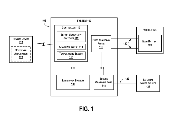
[0010] Figure 1 is a block diagram representing a smart battery backup
system
configured to connect to a main battery of a vehicle, in accordance with an
example
embodiment.
[0011] Figure 2 is a flow chart depicting example operations, in
accordance with an
example embodiment.
[0012] Figure 3 is another flow chart depicting example operations, in
accordance
with an example embodiment.
[0013] Figure 4 depicts an example of the system of Figure 1, in
accordance with an
example embodiment.
[0014] Figure 5 depicts another example of the system of Figure 1, in
accordance
with an example embodiment.
DETAILED DESCRIPTION
[0015] Disclosed embodiments will now be described more fully hereinafter
with
reference to the accompanying drawings, in which some, but not all of the
disclosed
embodiments are shown. Indeed, several different embodiments may be provided
and should
not be construed as limited to the embodiments set forth herein. Rather, these
embodiments
are provided so that this disclosure will be thorough and complete and will
fully convey the
scope of the disclosure to those skilled in the art.
[0016] Figure I is a block diagram representing a smart battery backup
system 100
(hereinafter referred to as "system 100") configured to connect to a main
battery 102 of a
vehicle 104, in accordance with an example embodiment. As shown, the system
100 can
include a housing 106. The system 100 can also include a lithium-ion battery
108 and a
controller 110, each of which can be at least partially disposed within the
housing 106 or at
least partially attached on an exterior the housing 106. The controller 110
can include a set of
momentary switches 112, a charging switch 114, and a temperature sensor 115.
[0017] The housing 106 can define a plurality of first charging ports 116.
The
housing 106 can also define a second charging port 118. The plurality of first
charging ports
116 can be configured to receive a plurality of first cables 120 that connect
the lithium-ion
battery 108, and thereby, the system 100, to the main battery 102 of the
vehicle 104. The
- 4 -
CA 03142152 2021-11-26
WO 2020/243707
PCT/US2020/035561
second charging port 118 can be configured to receive a second cable 122 that
connects the
lithium-ion battery 108, and thereby, the system 100, to an external power
source 124. As
further shown, the controller 110, and thus, the system 100, can be in
communication with a
remote device 126.
[0018] The main battery 102 can be a rechargeable battery configured to
supply
current to the vehicle 104. The main battery 102 can take various forms,
depending on the
type of the vehicle 104.
[0019] The vehicle 104 can be one of a variety of different types of
vehicles, such as
a car, truck, lawnmower, golf cart or other sports-related vehicle, or marine-
based vehicle
(e.g., a boat), among many other possibilities. As such, the main battery 102
of the vehicle
104 can be a standard battery commonly found in the vehicle 104, or can
instead be a
separate battery that was installed to replace the battery that is typically
included with the
vehicle 104.
[0020] The housing 106 can be comprised of plastic and/or other materials.
In some
embodiments, the housing 106 can include, in addition to the components
discussed above,
one or more physical structures that enable the system 100 to be mounted or
otherwise
affixed to one or more surfaces within the vehicle 104 when the system 100 is
installed in or
on the vehicle 104. Additionally or alternatively, the system 100 can be
affixed to the vehicle
104 via push pins, clamps, adhesives, or other mounting techniques/mechanisms.
The
location at which the system 100 is mounted in or on the vehicle 104 can vary
depending on
the location of the main battery 102 and/or depending on the layout and
configuration of the
vehicle 104 itself (e.g., how much space is available for mounting, how far
the mounting
space is from the main battery 102, etc.). For instance, the system 100 can be
mounted under
the dashboard (e.g., under the glove compartment on the passenger side), in
the glove
compartment, in the trunk of the vehicle 104, or under the hood of the vehicle
104, among
other possible locations.
[0021] The lithium-ion battery 108 can be a rechargeable battery to and
from which
current can flow during charging of the lithium-ion battery 108 and
discharging of the
lithium-ion battery 108. Although embodiments herein are described as
including a lithium-
ion battery, it should be understood that, in other embodiments, the system
100 could include
other types of batteries additionally or alternatively to a lithium-ion
battery. The size of the
lithium-ion battery 108, and perhaps additionally the size of the housing 106
and/or the
- 5 -
CA 03142152 2021-11-26
WO 2020/243707
PCT/US2020/035561
controller 110, can vary depending on the type of vehicle 104. For instance,
the lithium-ion
battery 108 and/or the controller 110 might be physically larger and/or more
powerful for
implementations of the system 100 that are used for larger vehicles such as
semi-trucks than
for those used for smaller vehicles such as sports cars.
[0022] The controller 110 can be or include one or more processors and/or
other
electronic components that facilitate control of operations performed by the
system 100,
including but not limited to the operations described herein. The controller
110 can take
various forms, such as that of a printed circuit board assembly. In
implementations where the
controller 110 includes a processor, such a processor can be a general-purpose
processor or
special purpose processor (e.g., a digital signal processor, application
specific integrated
circuit, etc.).
[0023] In some implementations, the controller 110 can include memory as
well,
which can take the form of one or more computer-readable storage media, such
as non-
transitory computer-readable media, that can be read or accessed by the
processor. The
computer-readable storage media can include volatile andlor non-volatile
storage
components, such as optical, magnetic, organic or other memory or disc
storage, which can
be integrated in whole or in part with the processor. The memory can store
instructions (e.g.,
computer-readable program instructions including computer executable code) and
the
processor can be configured to execute those instructions to cause the
controller 110 to
perform various operations described herein.
[0024] The memory can store other data as well in addition to executable
instructions,
such as temperature data acquired by the temperature sensor 115, a current or
previous charge
state of the lithium-ion battery 108, a current or previous charge state of
the main battery 102,
and/or usage counter data such as (i) how many times the system 100 has been
powered on,
(ii) a total time during which the system 100 has been powered on, (iii) how
many times one
or more of the jump starting operations have been performed, and/or (iv) how
many times
one or more of the self-maintaining operations have been performed.
[0025] In some examples, the memory can be implemented using a single
physical
device (e.g., one optical, magnetic, organic or other memory or disc storage
unit), while in
other examples, the memory can be implemented using two or more physical
devices.
[0026] In other implementations, the set of momentary switches 112, the
charging
switch 114, and/or other parts of the controller 110 can include additional or
alternative
- 6 -
CA 03142152 2021-11-26
WO 2020/243707
PCT/US2020/035561
components as well, such as a relay that enables or disables current flow
between the lithium-
ion battery 108 and the main battery 102.
10027] The set of momentary switches 112 can be or include one or more
momentary
switches and associated circuitry, each of which can take the form of a
physical mechanical
switch or a solid state switch that is configured such that, when activated,
the momentary
switch electrically connects the lithium-ion battery 108 of the system 100 in
parallel with the
main battery 102 of the vehicle 104. In some implementations, when such a
switch is
activated, activation of the switch can trigger a time-delayed relay, which
connects the
lithium-ion battery 108 in parallel with the main battery 102 for a
predetermined duration of
time (e.g., thirty seconds), during which the lithium-ion battery 108 can jump
start the main
battery 102. If the controller 110 detects that the lithium-ion battery 108 is
insufficiently
charged (e.g., has charge state that is below a predetermined threshold) or
otherwise becomes
insufficiently charged before the predetermined duration of time expires, the
controller 110
might shut the system 100 off or perform another action. Further, in some
implementations,
the set of momentary switches 112 can include multiple switches for redundancy
purposes in
the event that one or more of them becomes inoperable.
100281 In some examples, one or more momentary switches of the set of
momentary
switches 112 can be or include a switch configured to be remotely and
wirelessly activated,
such as by way of radio frequency signals (e.g., radio waves used for radio-
frequency
identification (RFID), Bluetootht communication, or other wireless technology
standards).
Additionally or alternatively, in some examples, one or more momentary
switches of the set
of momentary switches 112 can be or include a switch configured to be manually
activated.
For example, one such switch can be or include a push button switch disposed
at least
partially within the housing 106 or located remotely from the housing 106 but
physically
connected to the rest of the controller 110 (e.g., via a wire or group of
wires). Other
examples are possible as well. A manually-activated switch can be advantageous
in various
situations, such as when a remote control for the remotely-activated
switch(es) is
nonfunctional or misplaced. In some implementations, one or more momentary
switches of
the set of momentary switches 112 can be integrated into a printed circuit
board of the
controller 110, or otherwise integrated with the controller 110. It should be
understood that
the system 100 can be additionally or alternatively configured such that any
one or more of
the set of momentary switches 112, when activated, can initiate the
performance of other
- 7 -
CA 03142152 2021-11-26
WO 2020/243707
PCT/US2020/035561
operations described herein, such as trickle charging, maintaining the main
battery 102,
and/or the lithium-ion battery 108 maintaining itself
[0029] In some
arrangements, the controller 110 can include at least one switch that,
when activated, does not connect the lithium-ion battery 108 to the main
battery 102, and at
least one other switch that, when activated after the system 100 is turned on,
connects the
lithium-ion battery 108 to the main battery 102.To facilitate operation of
certain types of
momentary switches, the system 100 can include additional components. For
example, if a
Bluetootht switch is present, the system 100 ¨ or, more particularly, the
controller 110 ¨ can
include a wireless communication module configured to receive a Bluetootht
signal and
responsively activate or deactivate the Bluetootht switch. Other examples are
possible as
well.
[0030] The
charging switch 114 can be or include one or more switches and
associated circuitry that is/are integrated into a printed circuit board of
the controller 110, or
otherwise integrated with the controller 110, and that facilitate electrically
connecting the
lithium-ion battery 108 to the main battery 102 or the external power source
124 so the
controller 110 can charge the lithium-ion battery using the main battery 102
or the external
power source 124. As an example, the charging switch 114 can be or include a
12.5 volt (V)
charging switch and associated circuitry. Further, the charging switch 114 can
be configured
such that, when activated (e.g., automatically by the controller 110 in
response to the
controller 110 determining that the lithium-ion battery 108 has a charge state
that is below a
predetermined threshold), the charging switch 114 connects the lithium-ion
battery 108 to the
main battery 102, thus facilitating charging of the lithium-ion battery 108
off the main battery
102. When the charging switch 114 is deactivated (e.g., by the controller 110
in response to
the controller 110 determining that a charge state of the lithium-ion battery
108 reaches a
predetermined threshold, or in response to the charge state of the main
battery 102 reaching
or falling below a predetermined deactivation threshold), the charging switch
114 can
disconnect the lithium-ion battery 108 from the main battery 102. In some
implementations,
the charging switch 114, when activated, can connect the external power source
124 to the
main battery 102 to facilitate trickle charging the main battery 102. In
other
implementations, another switch or switches and associated circuitry, separate
from the
charging switch 114, can be integrated with the controller 110 and dedicated
for use in
connecting the external power source 124 to the main battery 102.
- 8 -
CA 03142152 2021-11-26
WO 2020/243707
PCT/US2020/035561
[0031] It should be noted that, in some embodiments, the set of momentary
switches
112 can be associated with a different type of charging than the charging
switch 114. In
particular, activation of one or more momentary switches of the set of
momentary switches
112 can trigger the operations of the controller 110 related to jump starting
the main battery
102 using the lithium-ion battery 108. By contrast, activation of the charging
switch 114 can
trigger operations of the controller 110 in which the lithium-ion battery 108
is charged off of
the main battery 102 via the plurality of first cables 120, but in which the
lithium-ion battery
108 is not supplying current to charge the main battery 102 and is not
connected in parallel
with the main battery 102. Thus, the connection between the lithium-ion
battery 108 and the
main battery 102 triggered by the activation of the charging switch 114 can be
different from
the connection between the lithium-ion battery 108 and the main battery 102
triggered by the
activation of one or more momentary switches of the set of momentary switches
112.
[0032] The temperature sensor 115 can be or include a thermocouple,
thermopile,
thermistor, and/or associated circuitry configured for sending signals to the
controller 110
that indicate one or more temperature levels within the system 100, such as a
temperature of
the lithium-ion battery 108. In an exemplary example, if the controller 110
receives a signal
that indicates that a temperature of the lithium-ion battery 108 is outside of
a predetermined
range (e.g., below -20 degrees Celsius or above 60 degrees Celsius), the
controller 110 can
responsively not allow the system 100 to be turned on so that the lithium-ion
battery 108
cannot connect to the main battery 102 and/or the external power source 124.
Alternatively,
if the lithium-ion battery 108 is currently connected to the main battery 102
and/or the
external power source 124, disconnect the lithium-ion battery 108 from the
main battery 102
and/or the external power source 124. Thus, the system 100 can help keep
itself at a safe
operating temperature. Other examples are possible as well.
[0033] In addition to the set of momentary switches 112, the charging
switch 114, and
the temperature sensor 115, the controller 110 can include a unidirectional
charging circuit
that can connect the lithium-ion battery 108 in parallel with the main battery
102 to allow for
jump starting (or otherwise providing charge to) the main battery 102. The
controller 110
(i.e., the circuits thereof) can be designed such that current can flow to and
from the lithium-
ion battery 108, but also such that, in some situations, drain of current from
the lithium-ion
battery 108 can be prevented. These and other operations performed by the
controller 110 are
described in more detail below.
- 9 -
CA 03142152 2021-11-26
WO 2020/243707
PCT/US2020/035561
[0034] The plurality of first charging ports 116 can be or include
mechanical and
electrical connectors configured to receive the plurality of first cables 120
and serve as a
bridge between the main battery 102 and the system 100. For example, the
plurality of first
charging ports 116 can be a female connectors configured to receive ends of
the plurality of
first cables 120. Other examples are possible as well.
[0035] The second charging port 118 can be or include a mechanical and
electrical
connector configured to receive the second cable 122 and serve as a bridge
between the
external power source 124 and the system 100 such that the main battery 102 is
electrically
coupled to the external power source 124 via the system 100. For example, the
second
charging port 118 can be a female connector configured to receive one end of
the second
cable 122. Other examples are possible as well. The second charging port 118
can be
configured to convert power from alternating current (AC) to direct current
(DC) while also
reducing the voltage to proper amperage for trickle charging.
[0036] The plurality of first cables 120 can be or include any wire or
grouping of
wires that hardwire, and thus electrically connect, the system 100 to the main
battery 102 of
the vehicle 104. Each of the plurality of first cables 120 can include a
respective terminal
(e.g., positive and negative) configured to connect to a respective
corresponding terminal of
the main battery 102. A variety of different accessories could be used to
connect the plurality
of first cables 120 to the terminals of the main battery 102, such as
nuts/screws or ring
terminals.
[0037] One advantage of the system 100 is that, rather than being a backup
system
such as a jump pack that is primarily intended for portable use, the system
100 can be affixed
to the vehicle 104 in a more permanent manner. In particular, a user can
connect the plurality
of first cables 120 to the main battery 102 in such a way so that the user
would not desire to
disconnect the plurality of first cables 120 for a long period of time (e.g.,
weeks, months, or
years). To that point, the mechanisms used to connect the system 100 to the
main battery 102
can be more permanent (e.g., ring terminals, screws, etc.) than alligator
clips or other types of
mechanisms that are used for more temporary connections. In other words, the
system 100
can be connected via ring terminals, screws, etc., and not by using alligator
clips or other
such mechanisms used for more temporary connections.
[0038] The second cable 122 can be or include any wire or grouping of
wires that
hardwire, and thus electrically connect, the system 100 to the external power
source 124. For
- 10 -
CA 03142152 2021-11-26
WO 2020/243707
PCT/US2020/035561
example, the second cable 122 can take the form of a 110 Volt (V) AC power
cable. Other
examples are possible as well.
[0039] The external power source 124 can be a device configured to supply
electrical
power, such as AC voltage, to the system 100. For example, the external power
source 124
can take the form of a 110 V power outlet, such as an outlet found in a house
or garage of a
user of the system 100. Other examples are possible as well.
[0040] The remote device 126 can be an electronic computing device,
possibly having
a processor and memory (either of which can take the forms described above by
way of
example with respect to the controller 110). The remote device 126 can be used
to remotely
interact with the system 100 and components thereof. For example, the remote
device 126
can be a wireless radio frequency controller configured with a button or other
input device
that, when triggered, causes radio frequency signals to be transmitted to the
controller 110
(e.g., to activate a radio frequency-based switch of the controller 110) to
cause the controller
110 to perform certain operations, such as initiating jump starting of the
main battery 102 off
of the lithium-ion battery 108. As another example, and as shown in Figure 1,
the remote
device 126 can be a client device (e.g., a personal computer, smartphone,
tablet computer,
wearable computing device, or other computing device) having installed a
software
application 128 associated with the system 100. Using the software application
128, a user
can make a selection that causes the remote device 126 to wirelessly (e.g.,
via Bluetoothe)
activate the controller 110 (e.g., activate a Bluetootht switch of the
controller 110) to cause
the controller 110 to perform certain operations, such as initiating jump
starting of the main
battery 102 off of the lithium-ion battery 108. The remote device 126 can take
other forms as
well, additionally or alternative to the forms described above.
[0041] Although not shown, the system 100 can include other components as
well,
additionally or alternatively to those described above. For example, the
system 100 can
include one or more light-emitting diodes (LEDs) configured to indicate a
charge state of the
lithium-ion battery 108. Other examples are possible as well.
[0042] The controller 110 can be configured to cause the system 100 to
perform
various operations, such as those related to jump starting the main battery of
the vehicle 104,
self-maintaining the lithium-ion battery 108, and trickle charging the main
battery 102, thus
integrating jump starting, self-maintaining, and trickle charging
functionality within the same
housing. Examples of these operations will now be described.
-11-
CA 03142152 2021-11-26
WO 2020/243707
PCT/US2020/035561
[0043] The controller 110 can be configured to perform jump starting
operations in
which the lithium-ion battery 108 is used to provide a voltage boost to the
main battery 102
of the vehicle 104 for a predetermined duration of time (e.g., somewhere
between 30 seconds
to 60 seconds) to start the vehicle 104.
[0044] In an example of this jump starting process, one or more switches
of the set of
momentary switches 112 can be activated, such as in one or more of the manners
described
above. Activation of the momentary switch(es) (e.g., receipt by the controller
110 of one or
more signals indicative of the activation, such as a Bluetootht signal) can
trigger a time-
delayed relay where, for a predetermined startup window of time (e.g., thirty
seconds, or long
enough for a user to start the vehicle), the controller 110 can connect the
lithium-ion battery
108 in parallel with the main battery 102 via the plurality of first cables
120 and jump start
the main battery 102 using the lithium-ion battery 108. The act of jump
starting the main
battery 102 can involve one or more attempts to jump start the main battery
102 within the
predetermined startup window. The controller 110 can stop trying to jump start
the main
battery 102 in response to the controller 110 detecting that the vehicle 104
has started, such
as by determining that the main battery 102 has exhibited a rise in voltage
exceeding a
particular threshold (e.g., 13 V to 14 V upon startup of the vehicle 104), or
in response to the
controller 110 detecting that the predetermined startup window has expired.
[0045] If, during the predetermined startup window, the controller 110
does not detect
that the vehicle 104 is running, the predetermined startup window will expire
and the set of
momentary switches 112 might have to be reactivated to reinitiate jump
starting of the
vehicle 104. Further, if the user desires to connect the lithium-ion battery
108 in parallel
again (e.g., because the vehicle did not start the first time), the controller
110 might not allow
the connection to occur until after the predeteHnined startup window has
expired, after which
the lithium-ion battery 108 can again be connected via one or more of the
momentary
switches of the set of momentary switches 112.
[0046] In some implementations, the jump starting operations can involve
the
controller 110 monitoring a charge state (e.g., a voltage) of the main battery
102 and, when
the controller 110 determines that the charge state has fallen below a
predetermined charge
drop threshold (e.g., approximately 12.5 V), the controller 110 can
responsively transmit, to
the remote device 126, an alert message (e.g., a text message, an audio
notification, etc.) to
notify a user of the remote device 126 that the main battery 102 is being
depleted. In some
- 12 -
CA 03142152 2021-11-26
WO 2020/243707
PCT/US2020/035561
examples, the alert message can be provided to the user via the software
application 128
installed on the remote device 126.
[0047] In addition to the jump-starting operations, the controller 110 can
be
configured to perform self-maintaining operations on the system 100 itself
Namely, the
controller 110 can cause the system 100 to charge itself off the main battery
102 via the
plurality of first cables 120.
[0048] In an exemplary implementation, the controller 110 can be
configured to
perform at least a portion of the self-maintaining operations described herein
on a continuous
basis (e.g., as long as the system 100 has power), at predefined periodic
intervals (e.g., every
minute), and/or in response to detecting one or more specific trigger
conditions, such as a
trigger condition where the controller 110 determines that the main battery
102 has exhibited
a rise in voltage exceeding a predetermined threshold (e.g., approximately
12.5 V). Thus, the
system 100 can advantageously check (e.g., continuously, or periodically,
etc.) to see if the
main battery 102 (or the external power source 124, if such a source is
connected to the
system 100) has sufficient voltage that the system 100 can use to maintain a
desirable
consistent charge state of the lithium-ion battery 108 without leaving the
main battery 102
with a less-than-desirable voltage. If the desired voltage is not available
from the main
battery 102 or the external power source 124, the controller 110 can wait for
the vehicle 104
to be running and/or for the system 100 to be connected to the external power
source 124. In
some implementations, the self-maintaining operations described herein can be
performed by
the system 100 regardless of whether the vehicle is running, sitting idle,
etc.
[0049] In an example of the self-maintaining operations, the controller
110 can
determine a charge state of the lithium-ion battery 108. The controller 110
can also
determine a charge state of the main battery 102 and/or determine whether the
system 100 is
connected to the external power source 124. If the controller 110 determines
that the charge
state of the lithium-ion battery 108 is below a first predetermined system
threshold (e.g.,
below approximately 90% of the full capacity of the lithium-ion battery 108,
or below
approximately full capacity) and determines that the charge state of the main
battery 102
exceeds a first predetermined vehicle threshold (e.g., exceeds 95% of the full
capacity of the
main battery 102), the controller 110 can responsively and automatically
connect the lithium-
ion battery 108 to the main battery 102 by activating the charging switch 114,
thus permitting
- 13 -
CA 03142152 2021-11-26
WO 2020/243707
PCT/US2020/035561
current flow from the main battery 102 to the lithium-ion battery 108, and
charge the lithium-
ion battery 108 via the plurality of first cables 120 and using the main
battery 102.
[0050] Additionally or alternatively, if the controller 110 determines
that the charge
state of the lithium-ion battery 108 is below the first predetermined system
threshold and
determines that the system 100 is connected to the external power source 124,
the controller
110 can responsively and automatically connect the lithium-ion battery 108 to
the external
power source 124 (e.g., by activating one or more switches, such as the
charging switch 114
or a different switch, that connect the lithium-ion battery 108 to the
external power source
1241), thus permitting current flow from the external power source 124 to the
lithium-ion
battery 108, and charge the lithium-ion battery 108 via the second cable 122
and using the
external power source 124. Further, in scenarios where the system 100 is
connected to the
external power source 124 and the charge state of the main battery 102 exceeds
the first
predetermined vehicle threshold, the controller 110 can be configured to
prioritize charging
the lithium-ion battery 108 directly using the external power source 124
instead of using the
main battery 102. A self-maintaining operation using the external power source
124 can be
particularly useful in scenarios where the vehicle 104 is being kept in a
garage or other
location for a long period of time or where the main battery 102 is otherwise
not available or
desirable for use in the self-maintaining of the system 100.
[0051] As noted above, the controller 110 can be configured in some
implementations
to determine the charge state of the lithium-ion battery 108, determine the
charge state of the
main battery 102, andlor determine whether the system 100 is connected to the
external
power source 124 in response to a trigger condition. As an example, the
trigger condition can
be the controller 110 determining that the main battery 102 has exhibited a
rise in voltage
exceeding a predetermined voltage rise threshold (e.g,, approximately 12.5 V).
Such a rise in
voltage can correspond to a startup of the vehicle 104, thus indicating to the
system 100 that
the vehicle 104 is on and running. As another example, the trigger condition
can be the
controller 110 detecting that the system 100 has been plugged into the
external power source
124. Other trigger conditions are possible as well.
[0052] In some implementations, the controller 110 can be configured to
connect the
lithium-ion battery 108 to the main battery 102 before determining the charge
state of the
lithium-ion battery 108. In such implementations, if the controller 110
deteintines that the
charge state of the lithium-ion battery 108 is below the first predetermined
system threshold
- 14 -
CA 03142152 2021-11-26
WO 2020/243707
PCT/US2020/035561
and makes one or more of the other determinations described above, the
controller 110 can
responsively then maintain the connection and begin charging the lithium-ion
battery 108 off
the main battery 102. Whereas, if the controller 110 determines that the
charge state of the
lithium-ion battery 108 is not below the first predetermined system threshold,
the controller
110 can responsively then disconnect from the main battery 102.
[0053] After the
controller 110 has begun charging the lithium-ion battery 108 as
described above, the controller 110 can keep charging the lithium-ion battery
108 until the
controller 110 makes one or more determinations that indicate to the
controller 110 that the
controller 110 should stop charging the lithium-ion battery 108. Thus, one
such
determination or combination of such determinations can cause the controller
110 to
responsively and automatically disconnect the lithium-ion battery 108 from the
main battery
102 by deactivating the charging switch 114 and/or responsively and
automatically stop
charging the lithium-ion battery 108 using the external power source 124.
[0054] One
example of such a determination can be the controller 110 determining
that the charge state of the lithium-ion battery 108 exceeds a second
predetermined system
threshold exceeds
95% of the full capacity of the lithium-ion battery 108) or has
reached approximately a full charge to 100% of the full capacity.
[0055] Another
example of such a determination can be the controller 110
determining that the charge state of the main battery 102 is below a second
predetermined
vehicle threshold (e.g., below 80% of the full capacity of the main battery
102). The first and
second predetermined system thresholds can be the same or different, and the
first and second
predetermined vehicle thresholds can be the same or different.
[0056] Yet
another example of such a determination can be the controller 110
determining that that system 100 has been disconnected from the external power
source 124.
[0057] Yet
another example of such a determination can be the controller 110
determining that the main battery 102 has exhibited a drop in voltage below
the
predetermined voltage drop threshold (e.g., the voltage of the main battery
102 has dropped
below approximately 12.5 V), which can indicate that the vehicle 104 has
turned off
[0058] As a
specific example of the self-maintaining operations, the controller 110, in
determining when to disconnect and stop charging the lithium-ion battery 108,
might be
configured to consider only whether the charge state of the main battery 102
is below the
second predetermined vehicle threshold. That is, even if the vehicle 104 is no
longer running,
- 15-
CA 03142152 2021-11-26
WO 2020/243707
PCT/US2020/035561
the lithium-ion battery 108 can continue to charge off the main battery 102
until the
controller 110 determines that the charge state of the main battery 102 is
below the second
predetermined vehicle threshold.
[0059] As another specific example of the self-maintaining operations,
upon starting
of the vehicle 104, the controller 110 might determine that the charge state
of the lithium-ion
battery 108 is below the first predetermined system threshold (e.g., below 90%
charged),
upon which the controller 110 can charge itself off of the main battery 102
until the controller
110 determines both (i) that system 100 has been disconnected from the
external power
source 124 and (ii) that the charge state of the main battery 102 is below the
second
predetermined vehicle threshold (e.g., 90% charged), in which case the
controller 110 can
automatically disconnect and stop charging. Other examples are possible as
well.
[0060] As another specific example of the self-maintaining operations,
when the
vehicle 104 is not running, the controller 110 can determine whether the
charge state of the
main battery 102 is below the second predetermined vehicle threshold. If the
charge state is
below the second predetermined vehicle threshold, the controller 110 will not
charge the
lithium-ion battery 108 until it detects either that (i) the system 100 has
been connected to the
external power source 124 (in which case the controller 110 will initiate
charging the lithium-
ion battery 108 using the external power source 124) or (ii) that the charge
state of the main
battery 102 is above the second predetermined vehicle threshold (in which case
the controller
110 will initiate the charging the lithium-ion battery 108 using the main
battery 102).
[0061] By having the controller 110 configured to be able to automatically
disconnect
the system 100 from the main battery 102 in the manners discussed above, the
system 100
can avoid over-charging the lithium-ion battery 108. This also allows the
system 100 to act
as a maintainer for the main battery 102 so that the main battery 102 is not
over-depleted
when the system 100 is self-maintaining and charging the lithium-ion 108
battery off the
main battery 102. The system 100 can also isolate itself from the main battery
102 and thus
prevent the lithium-ion battery 108 from being depleted by an electrical
system or other
components of the vehicle 104 during normal vehicle operation (e.g., when the
vehicle is on,
such as when moving or when sitting still with lights on).
[0062] Additionally or alternatively to the criteria described above,
other criteria
could be used in the self-maintaining operation to determine whether to charge
the lithium-
ion battery 108 or whether to discontinue charging the lithium-ion battery
108.
- 16-
CA 03142152 2021-11-26
WO 2020/243707
PCT/US2020/035561
100631 As so configured, the system 100 can effectively include a
mechanism that is
integrated within the housing 106 that the system 100 can use to automatically
maintain the
lithium-ion battery 108 at a desirable charge state while also maintaining the
main battery
102 at a desirable charge state. Further, because the system 100 can be
usefully affixed to the
main battery 102 and the vehicle 104 in a more permanent manner than existing
solutions, the
self-maintaining functionality thus usefully becomes a more permanent
capability of the
system 100 that can be used with the vehicle 104 and/or the external power
source 124 when
desired.
100641 In addition to the jump starting and self-maintaining operations
described
above, the controller 110 can also be configured to automatically trickle
charge the main
battery 102 as needed. That is, the controller 110 can be configured to charge
the main
battery 102 in response to determining that the charge state of the main
battery 102 has fallen
below a first predetermined trickle charging threshold (e.g., 80% of the full
capacity of the
main battery 102).
100651 As noted above, the system 100 can facilitate trickle charging of
the main
battery 102 via a connection of the second cable 122 between the second
charging port 118
and the external power source 124. The second charging port 118 can convert
power from
AC to DC while also reducing the voltage to proper amperage for the trickle
charging (e.g.,
an amperage in the range of 100 milliamps to 200 milliamps). The controller
110 can include
a circuit that connects the second charging port 118 to the plurality of first
cables 120 so that
current can flow from the external power source 124, through the second cable
122, the
controller 110, and the plurality of first cables 120, to the main battery
102.
100661 In a more specific example of trickle charging operations, the
controller 110
can determine that the charge state of the main battery 102 has fallen below
the first
predetermined trickle charging threshold (e.g., below 80% of the full capacity
of the main
battery 102, or perhaps below approximately 100% of the full capacity) and
responsively
connect the main battery 102 to the external power source 124, such as by
activating a switch
in the circuitry of the controller 110 that is dedicated for use in activating
or deactivating
trickle charging functionality. The main battery 102 can thus be charged by
the external
power source 124 until the controller 110 determines that the charge state of
the main battery
102 has reached a second predetermined trickle charging threshold (e.g., 95%
of the full
capacity of the main battery 102, or perhaps approximately 100%), in which
case the
- 17-
CA 03142152 2021-11-26
WO 2020/243707
PCT/US2020/035561
controller 110 can responsively disconnect the external power source 124 from
the main
battery 102 (e.g., by deactivating a switch), thus discontinuing the charging.
The controller
110 can thereafter continue to monitor the charge state of the main battery
102 and can be
configured to automatically reconnect (e.g., by reactivating a switch) the
external power
source 124 to the main battery 102 in response to the controller 110
determining that the
charge state of the main battery 102 has again dropped below the first
predetermined trickle
charging threshold, so as to help maintain the charge state of the main
battery 102 at or above
approximately the second predetermined trickle charging threshold. In some
examples, as the
main battery 102 charge state approaches an output voltage of the external
power source 124
and gets closer to becoming fully charged, the current being supplied to the
main battery 102
via the controller 110 will naturally decline to zero.
[0067] As so configured, the system 100 can effectively include an
integrated trickle
charger within the housing 106 that can be used to extend the battery life of
the main battery
102 as needed, or to otherwise provide desired charge to the main battery 102.
Further,
because the system 100 can be usefully affixed to the main battery 102 and the
vehicle 104 in
a more permanent manner than existing solutions, the trickle charging
functionality thus
usefully becomes a more permanent capability of the system 100 that can be
used with the
vehicle 104 when desired.
[0068] In a preferred implementation, multiple components of the system
100
described above, including but not limited to the lithium-ion battery 108 and
the controller
110, are all contained within the same housing 106, so that the system 100 is
a single product
that integrates the jump starting functionality, the self-maintaining
functionality, and the
trickle charging functionality described above. In other words, at least the
controller 110 and
the lithium-ion battery 108 are located only within the housing 106 and not
located outside of
the housing 106. In other exemplary implementations, the controller 110 and/or
the lithium-
ion battery 108 can be at least partially within the housing 106 with at least
a portion (e.g., a
few centimeters) of one or both of such components located outside the housing
106. In
these and other preferred or exemplary implementations, the housing 106 is not
the same as
another type of housing that might be naturally present as part of the vehicle
104. That is, the
housing 106 (and the system 100, for that matter), can be a separate single
product that can be
connected to the main battery 102 of the vehicle 104. Furtheimore, as
discussed above,
preferred implementations for using the system 100 can involve fixedly
attaching the system
- 18 -
CA 03142152 2021-11-26
WO 2020/243707
PCT/US2020/035561
100 within the vehicle 104, such as inside an engine compartment of a vehicle
(e.g., under the
hood of a vehicle, under a seat of the vehicle, in a trunk of a vehicle,
etc.).
[0069] It should be understood that the act of disconnecting the lithium-
ion battery
108 from the main battery 102 described herein, and thus discontinuing
charging of the
lithium-ion battery 108 using the main battery 102 or vice versa, can involve
deactivating a
switch (e.g., the set of momentary switches 112, the charging switch 114,
and/or another
switch of the controller 110 not explicitly illustrated herein) such that
current does not flow
between the lithium-ion battery 108 and the main battery 102, even if a
physical connection
remains between the system 100 and the main battery 102 (e.g., the plurality
of first cables
120).
[0070] In some implementations, the system 100 can usefully interact with
remote
devices (e.g., remote device 1261) in manners additionally or alternatively to
the manners
described above. The nature of these interactions and associated operations
will now be
described in more detail.
[0071] In an example, the controller 110 can connect to the main battery
102 to
monitor a charge state of the main battery 102 and/or the lithium-ion battery
108 and
transmit, to the remote device 126, an indication of the charge state during
jump starting, self-
maintaining, and/or trickle charging. Thus, by way of the remote device 126, a
user of the
remote device 126 can be kept up to date in real time as to the charge status
during the jump
starting, self-maintaining, and/or trickle charging operations. The remote
device 126 can
include a display device (e.g., a computer monitor, touchscreen, etc.) that
can display the
indication. The indication of the charge state can take various forms, such as
a text message
or email sent to, and displayed by, the remote device 126, possibly
representing the charge
status as a number percentage of the full capacity. Other indications can be
provided to the
remote device 126 as well, such as a current temperature of the lithium-ion
battery 108 that is
detected by the temperature sensor 115, and/or an indication that the
temperature of the
lithium-ion battery 108 is within or outside of a predefined range.
[0072] In implementations where the software application 128 is installed
on the
remote device 126, the software application 128 can provide a graphical user
interface (GUI)
that enables the user to view the charge status of the main battery 102 and/or
the lithium-ion
battery 108. The software application 128 can also enable the user to view the
charge status
of the main battery of other vehicles in or on which other systems similar to
or identical to the
- 19-
CA 03142152 2021-11-26
WO 2020/243707
PCT/US2020/035561
system 100 have been installed.
[0073] The software application 128 and its user interface can provide
other
functionality to the user as well that assists the user with controlling
operation of the system
100 and/or monitoring any of the information described herein that is
determined by the
controller 110, such as whether the system 100 is connected to the main
battery 102, whether
the vehicle 104 is running, how much of the predetermined startup window has
expired,
and/or a temperature of the lithium-ion battery 108, among other
possibilities. More specific
examples of this functionality will now be described in more detail.
[0074] In an example implementation, the software application 128 can
enable the
user to add or remove the system 100 from the memory of the remote device 126.
For
example, to add the system 100, the software application 128 can provide a
page that prompts
the user to scan a QR code or other readable code using a camera of the remote
device 126 or
to enter a registration code manually.
[0075] Once the system 100 is added, the software application 128 can
provide
various information to, or request various information from the user, which
can be provided
in a single page or multiple pages. Examples of this information can include a
name/nickname for the system 100 (e.g., "My System") and/or details of the
vehicle 104
(e.g., make, model, year, vehicle identification number, license plate number,
stock, color).
[0076] The software application 128 can list all registered systems and
display a
status for each system, such as whether the system 100 is within range, out of
range, or
unavailable (e.g., if the remote device 126 is within range of the system 100,
but the lithium-
ion battery 108 is dead, the controller 110 or Bluetooth module is
experiencing an error,
etc.). Other status information is possible as well, such as a charge status
of the lithium-ion
battery 108, a charge status of the main battery 102, a warning that the
lithium-ion battery
108 and/or the main battery 102 will soon be depleted, and/or a status of the
vehicle 104 (e.g.,
whether the vehicle 104 is running or not). The software application 128 can
also display a
date and time at which the status of the system 100 was last updated.
[0077] In some implementations, the software application 128 can provide a
single
GUI element on a page having its appearance (e.g., color) change depending on
what
operations are being performed or can be performed with respect to the system
100, and/or
depending on whether the status of the system 100 is within range, out of
range, out of a safe
operating temperature range, etc. As an example the GUI element can, when
selected,
- 20 -
CA 03142152 2021-11-26
WO 2020/243707
PCT/US2020/035561
connect the remote device 126 to the controller 110, provided that the system
100 is within
range. The GUI element and/or another part of the page can then display a
connection status
(e.g., a progress bar), as well as an indication as to whether the connection
was successful or
unsuccessful. After the connection (e.g., a wireless communication interface)
is successfully
established, the GUI element can enable the user to -swipe to start- a
particular operation.
As a more specific example, the user can swipe to start the jump starting
operation, which
causes the remote device 126 to transmit a signal to the controller 110 that,
upon receipt by
the controller 110, causes the controller 110 to responsively connect the main
battery 102 in
parallel with the lithium-ion battery 108 and jump start the vehicle 104.
However, if the
controller 110 does not detect that the vehicle 104 is running in the
predetermined startup
window, the controller 110 will stop trying to jump start the vehicle 104 and
the user will
have to swipe to start again to reinitiate the jump start process, thus
restarting the
predetermined startup window.
[0078] The software application 128 can also enable the user to share the
system 100
with another user. This might occur, for instance, if the user sells the
vehicle 104 (which has
the system 100 installed), to the other user and seeks to relinquish control
of the system 100
to the other user. To facilitate this, the software application 128 can
provide a selectable
option to initiate a transfer of the system 100 information and the vehicle
104 information to
the other user. For instance, the software application 128 can generate a QR
code that, when
scanned by a remote device of the other user, can cause the information to be
transferred to
the remote device of the other user. In some situations, the information might
also be
automatically deleted from the remote device 126, but in other situations, the
information
might remain on both the remote device 126 and the other user's remote device
(e.g. the
devices of two family members who are sharing the vehicle 104).
[0079] The software application 128 can provide other helpful information
as well,
such as a frequently asked questions page and a helpdesk chat interface.
[0080] In some implementations, the above-described interactions with the
remote
device 126 and the software application 128 might only occur when the remote
device 126 is
within Bluetoothe range and/or have a Wi-Fi connection. Further, in some
implementations,
the system 100 can send notifications to the remote device 126 via another
device (not
shown), such as a Wi-Fi wall adapter or other device that has a 1A/i-Fi
connection. To
facilitate this, the other device can be plugged in to a 110 V power outlet
and can be
-21 -
CA 03142152 2021-11-26
WO 2020/243707
PCT/US2020/035561
configured to be connected to a Wi-Fi network (e.g., a home of the vehicle
owner). As such,
the system 100 can have a Wi-Fi connection by communicating with the other
device via
Bluetootht and can send notifications to the remote device 126 as long as the
remote device
126 has a type of wireless signal (e.g., cell service or a Wi-Fi connection of
its own). Other
examples are possible as well.
[0081] The system 100 described above can provide various advantages over
existing
backup systems. For example, existing systems can include a main vehicle
battery integrated
with wireless jump-starting capabilities, but such systems might not provide
self-maintaining
capabilities and/or trickle charging capabilities integrated within or with a
single housing and
system that can be installed in or on a vehicle. Further, such existing
systems can be limited
to particular markets (e.g., the automotive market) and might require more
maintenance than
desired. Some existing systems can include a jump starter accessory that is
portable and
separate from a main battery of a vehicle. Some existing systems also have
limited battery
sizes or otherwise are only able to be used in certain vehicles. And some
existing systems
also must be manually charged on a regular basis and manually
connected/disconnected from
a vehicle on a regular basis.
[0082] By contrast, the system 100 serves as a separate, smart, self-
maintaining,
adaptable accessory that can be installed into a large variety of vehicles
across multiple
markets (e.g., cars, trucks, lawnmowers, golf carts, etc.), connected to an
existing main
battery of a vehicle, can be ready for use as an at least partially autonomous
jump starter,
self-maintainer, and/or trickle charger as-needed because such functionality
is integrated
therein, and can function as a cheaper, streamlined, less complex, and more
permanent
accessory requiring less maintenance than existing systems. For instance, by
having an
intelligent controller that monitors charge states of the main battery and the
disclosed
system's own lithium-ion battery, as well as automatically initiates charging
of the main
battery or lithium-ion battery in response to certain conditions being met,
the disclosed
system can reduce or eliminate the need for a user to manually monitor these
charge states or
perform other manual maintenance on the main battery or the disclosed system.
The system
100 is also designed to be installed in such a way that the system 100 remains
on or within
the vehicle 104 during most if not all of the vehicle's operations, including
when the vehicle
104 is travelling, when the vehicle 104 is not travelling (e.g., in a garage),
when the vehicle
- 72 -
CA 03142152 2021-11-26
WO 2020/243707
PCT/US2020/035561
104 is idle, etc., thus making the system 100 a permanent or semi-permanent
component of
the vehicle 104. Other advantages are possible as well.
[0083] Figure 2 is a flow chart depicting an example of a method 200, in
accordance
with an example embodiment. In particular, the flow chart of Figure 2 depicts
example
operations relating to the jump-starting operations described above. Method
200 may include
one or more operations, functions, or actions as illustrated by one or more of
blocks 202-204.
[0084] At block 202, functions include receiving a signal indicative of
activation of
the set of momentary switches.
[0085] At block 204, functions include in response to receiving the
signal, and within
a predetermined startup window from receiving the signal, jump starting the
main battery
using the lithium-ion battery.
[0086] Figure 3 is another flow chart depicting example operations, in
accordance
with an example embodiment. In particular, the flow chart of Figure 3 depicts
example
operations relating to the self-maintaining operations described above. Method
300 may
include one or more operations, functions, or actions as illustrated by one or
more of blocks
302-306.
[0087] At block 302, functions include determining that a charge state of
the lithium-
ion battery is below a first predetermined system threshold.
[0088] At block 304, functions include determining that a charge state of
the main
battery exceeds a first predetermined vehicle threshold.
[0089] At block 306, functions include in response to determining that the
charge
state of the lithium-ion battery is below the first predetermined system
threshold and
determining that the charge state of the main battery exceeds the first
predetermined vehicle
threshold, automatically activating the charging switch to connect the lithium-
ion battery to
the main battery and charging the lithium-ion battery using the main battery.
[0090] Devices or systems may be used or configured to perform logical
functions
presented in Figures 2 and 3. In some instances, components of the devices
and/or systems
may be configured to perform the functions such that the components are
actually configured
and structured (with hardware andlor software) to enable such performance. In
other
examples, components of the devices and/or systems may be arranged to be
adapted to,
capable of, or suited for performing the functions, such as when operated in a
specific
manner. Although the operations in Figures 2 and 3 are illustrated in a
sequential order, these
- 23 -
CA 03142152 2021-11-26
WO 2020/243707
PCT/US2020/035561
operations may also be performed in parallel, and/or in a different order than
those described
herein. Also, the operations may be combined, divided, and/or removed based
upon the
desired implementation.
[0091] Furthermore each block or portions of each block may represent a
module, a
segment, or a portion of program code, which includes one or more instructions
executable
by a processor for implementing specific logical functions or steps in the
process. The
program code may be stored on any type of computer readable medium or data
storage, for
example, such as a storage device including a disk or hard drive. Further, the
program code
can be encoded on a computer-readable storage media in a machine-readable
format, or on
other non-transitory media or articles of manufacture. The computer readable
medium may
include non-transitory computer readable medium or memory, for example, such
as
computer-readable media that stores data for short periods of time like
register memory,
processor cache and Random Access Memory (RAM). The computer readable medium
may
also include non-transitory media, such as secondary or persistent long term
storage, like read
only memory (ROM), optical or magnetic disks, compact-disc read only memory
(CD-
ROM), for example. The computer readable media may also be any other volatile
or non-
volatile storage systems. The computer readable medium may be considered a
tangible
computer readable storage medium, for example.
[0092] In addition, each block or portions of each block in Figures 2 and
3 may
represent circuitry that is wired to perfoini the specific logical functions
in the process.
Alternative implementations are included within the scope of the examples of
the present
disclosure in which functions may be executed out of order from that shown or
discussed,
including substantially concurrent or in reverse order, depending on the
functionality
involved, as would be understood by those reasonably skilled in the art.
[0093] Any one or more of the jump-starting, self-maintaining, trickle
charging,
and/or main battery maintaining operations described above can be represented
as a block in
a method that is performed by the controller 110.
[0094] Figure 4 depicts an example of the system 100, in accordance with
an example
embodiment. In particular, Figure 4 depicts the housing 106 (which is closed),
the plurality
of first charging ports 116, the second charging port 118, the plurality of
first cables 120, and
an example form that one of the set of momentary switches 112 can take ¨
namely, a
manually-activated push button.
- 24 -
CA 03142152 2021-11-26
WO 2020/243707
PCT/US2020/035561
100951 Figure 5 depicts another example of the system 100, in accordance
with an
example embodiment. In particular, Figure 5 depicts the system 100 where a lid
of the
housing 106 is removed and components within the housing 106 are in view. As
shown,
Figure 5 depicts the lithium-ion battery 108, the controller 110, the
plurality of first charging
ports 116, the second charging port 118, and the plurality of first cables
120. In addition,
Figure 5 depicts a wireless communication module 500 (e.g., Bluetoothe module)
that can be
disposed within the housing 106 and can be connected to, or be integrated as
part of, the
controller 110. Further, Figure 5 depicts a plurality of LEDs 502 that
indicate a charge state
of the lithium-ion battery 108.
100961 The description of the different advantageous embodiments has been
presented for purposes of illustration and description, and is not intended to
be exhaustive or
limited to the embodiments in the form disclosed. Many modifications and
variations will be
apparent to those of ordinary skill in the art. Further, different
advantageous embodiments
may provide different advantages as compared to other advantageous
embodiments. The
embodiment or embodiments selected are chosen and described in order to best
explain the
principles of the embodiments, the practical application, and to enable others
of ordinary skill
in the art to understand the disclosure for various embodiments with various
modifications as
are suited to the particular use contemplated.
[0097] By the term "substantially," "approximately," or "about" used
herein, it is
meant that the recited characteristic, parameter, value, or geometric
planarity need not be
achieved exactly, but that deviations or variations, including for example,
tolerances,
measurement error, measurement accuracy limitations and other factors known to
skill in the
art, may occur in amounts that do not preclude the effect the characteristic
was intended to
provide.
- 25 -