Note: Descriptions are shown in the official language in which they were submitted.
CA 03142183 2021-11-29
WO 2020/239408
PCT/EP2020/062990
1
Apparatus and system for preparing an iced tea or coffee beverage
Technical Field
This disclosure relates to iced coffee and tea beverages, an apparatus for
making the beverages
and a system using the apparatus. In particular, the disclosure relates to an
aerated ice beverage
with a creamy mouthfeel and a long stability once prepared.
Background
It is well known to provide consumers with ice in their beverages to provide
greater refreshment.
Beyond simply adding ice-cubes, it is well known to provide beverages such as
slush-puppie rtm
style drinks made by constantly agitating a strongly refrigerated beverage
concentrate. Such
scraped beverages contain small rough ice fragments and have a slurry-like
mouthfeel for the
consumer.
Alternatively, beverages may be produced by blending ice cubes with a beverage
liquor to
produce a beverage with ice flakes distributed therein. This relies on a high
speed blender having
cutting blades. An example of such beverages based primarily on coffee
beverages are so-called
Frappuccinos rtm. While such iced beverages are prepared with a pleasant
appearance, they
typically melt quickly when provided to the consumer and there is a consequent
formation of a
watery layer from the melted ice which is devoid of the flavouring present in
the rest of the
beverage. Furthermore, even when freshly prepared, the ice flakes are visible
as agglomerates
and are discernible to the consumer on drinking the beverage.
W02014/135886 describes an apparatus for generating a slush containing frozen
and non-
frozen liquid. The slush is made from a draught beverage, such as beer, lager
or cider.
Figure 1 reproduces a diagrammatic view of the apparatus of W02014/135886. The
apparatus is
in the form of a slush machine 18 and comprises a freeze conduit 3 for liquid
110, the conduit
having an inlet 103 and an outlet 104 defining a volume 105 therebetween. A
pump 2 feeds liquid
through the volume 105 from the inlet 103 to the outlet 104 where it is then
re-circulated back to
the inlet 103 via conduit 1. Conduit 1 and freeze conduit 3 together define a
conduit loop for
recirculation of liquid. Slush can be dispensed from the loop from a
dispensing outlet 8, the loop
being replenished via a conduit loop inlet 7 from a reservoir 17.
An insulated slush recirculation umbilical 10 is added between the slush
machine 18 and the
dispensing outlet 8.
CA 03142183 2021-11-29
WO 2020/239408
PCT/EP2020/062990
2
The freeze conduit 3 forms one half of a heat exchanger 6 with a cooling
conduit 108 having an
inlet 106 and an outlet 107 and containing a body of liquid glycol coolant 109
therebetween. Heat
exchanger 6 is connected to a coolant loop that, as indicated by arrow A,
circulates the liquid
coolant from the inlet 106 to the outlet 107 to a coolant refrigeration unit
22 and then back to the
inlet 106. The coolant is provided to the inlet of the cooling conduit at a
temperature below the
freeze point of the liquid; thus, when the coolant flows within the cooling
conduit thermal heat
transfer occurs from the liquid to the coolant. Coolant refrigeration unit 22
is a glycol chiller which
includes a vapour compression refrigeration system 21 that is used to cool a
reservoir of coolant
20. Pump 19 is integrated into the chiller unit and provides the motive force
to re-circulate the
coolant.
The rate of flow of liquid coolant through the cooling conduit 108 can be
varied, thereby varying
the rate of heat transfer out of the liquid in the volume 105 of the freeze
conduit 3. By varying the
flow rate of fresh coolant into the cooling conduit a net increase or decrease
in the average
temperature of the coolant within the cooling conduit is effected: this
changes the overall thermal
heat transfer rate from the working fluid to the coolant and hence the freeze
rate in the working
fluid flowing within the freeze conduit.
Flow through the cooling conduit is controlled by a valve 24. A lower rate of
heat transfer is
achieved by shutting off the coolant fluid flow rate to substantially zero so
that there is no flow of
coolant through the cooling conduit 108. A higher rate of heat transfer is
achieved by opening
valve 24 to allow flow of coolant through the cooling conduit 108.
An additional coolant bypass loop 111 is provided for diverting coolant flow
away from the
cooling conduit 108. Flow through this loop is controlled as required by a
normally open valve 23.
Valves 23, 24 are controlled by a controller 15 in dependence on a sensor 4 to
sense the fraction
of frozen liquid in the generated slush. The sensor 4 is provided in the
conduit loop 1 immediately
upstream of the conduit inlet 103. The controller 15 can vary the heat
transfer out of the liquid in
volume 105 between different rates by controlling the flow of liquid coolant
through the cooling
conduit 108 in dependence on the output from the sensor 4. In an idle state,
the machine is only
required to overcome the base energy gains in the system to maintain the
ice/liquid ratio of the
working fluid in the re-circulated loop to the pre-set level desired. Thus,
the lower rate of heat
transfer is set by shutting the valve 24 to prevent flow of coolant through
the cooling conduit 108.
When dispense occurs, the volume of semi frozen working fluid dispensed is
replaced with
unfrozen working fluid from the reservoir 17. This results in a rapid
reduction in the solid fraction
of the fluid within the re-circulated loop that is sensed by the sensor 4,
causing the control
system to increase the rate of heat transfer out of the freeze conduit by
opening valve 24
CA 03142183 2021-11-29
WO 2020/239408
PCT/EP2020/062990
3
W02018/122277 describes an apparatus and method for preparing an ice-
containing tea or
coffee beverage. The method comprises (i) providing a beverage liquor
containing soluble tea or
coffee solids, and a freezing-point suppressant; (ii) aerating the beverage
liquor by the addition of
a gas; (iii) flowing the aerated, preferably sweetened, beverage liquor
through a refrigeration
system to cool the aerated beverage liquor and to thereby form a plurality of
ice crystals within
the aerated beverage liquor; and (iv) dispensing the cooled aerated beverage
liquor as an ice-
containing tea or coffee beverage.
Figure 2 reproduces a schematic of the apparatus of W02018/122277. The
apparatus 201
comprises a reservoir 205 for holding a beverage liquor. The reservoir 205 is
connected via a
supply duct 210 to a refrigeration circuit 215. The refrigerant circuit 215
comprises a plastic duct
216 within which the liquor flows, which has a recycle loop to permit the
liquor to recirculate
within the circuit 215. The refrigeration circuit 215 comprises a heat
exchanger 220 for cooling
the liquor using pre-chilled refrigerant which is flowed within a separate
duct 225.
The refrigeration circuit 215 is also in fluid communication with a dispensing
outlet 230 for
dispensing an ice-containing tea or coffee beverage from the refrigeration
circuit 215 into a
receptacle 235.
A source of pressurised gas 240 is provided to supply pressurised gas into the
supply duct 210
for aerating the beverage liquor. The gas may be supplied through a nozzle
having a plurality of
inlets to encourage the formation of fine bubbles. The gas mixing may also or
alternatively
involve a static mixer or one or more constricting orifices 241. A pump 245 is
also provided to
circulate the beverage within the refrigeration circuit 215.
The apparatus 201 allows the preparation of an ice-containing tea or coffee
beverage. Beverage
liquor containing soluble tea or coffee solids and a freezing point
suppressant is pumped or
driven with pressurised gas from the reservoir 205, through the supply duct
210 to the
refrigeration circuit 215. Gas is dosed into the supply duct 210 from the gas
source 240 via
mixing means 241. The liquor circulates, driven by the pump 245, within the
refrigeration circuit
215 and through the heat exchanger2 20, where it is cooled so that ice
crystals form slowly. An
ice-containing tea or coffee beverage is dispensed on demand from the circuit
215 via the outlet
230 into the beverage receptacle 235.
While the apparatus of W02014/135886 is able to generate a slush containing
frozen and non-
frozen liquid and the apparatus of W02018/122277 is able to prepare an ice-
containing tea or
coffee beverage, it would be desirable to improve the apparatus described.
CA 03142183 2021-11-29
WO 2020/239408
PCT/EP2020/062990
4
Summary of the Disclosure
According to a first aspect of the disclosure there is provided an apparatus
for preparing an ice-
containing tea or coffee beverage, the apparatus comprising:
a) a beverage concentrate reservoir containing a beverage concentrate;
b) a sweetener concentrate reservoir containing a sweetener concentrate;
c) a water pre-chiller containing or supplied with water;
d) a first pre-mixer for mixing the beverage concentrate supplied from the
beverage
concentrate reservoir with water supplied from the water pre-chiller;
e) a second pre-mixer for mixing the sweetener concentrate supplied from the
sweetener
concentrate reservoir with water supplied from the water pre-chiller;
f) a mixing chamber for mixing an output from the first pre-mixer with an
output from the
second pre-mixer to form a beverage liquor;
g) a cooling unit containing a coolant;
h) an ice-generating system;
i) a beverage product circuit for supplying the beverage liquor from the
mixing chamber to
the ice-generating system;
j) a cooling circuit for supplying coolant from the cooling unit to the ice-
generating system
to cool the beverage liquor and to thereby form a plurality of ice crystals
within the beverage
liquor; and
k) a beverage dispensing outlet for dispensing the ice-containing tea or
coffee beverage
from the ice-generating system into a receptacle.
The present disclosure will now be further described. In the following
passages different aspects
of the disclosure are defined in more detail. Each aspect so defined may be
combined with any
other aspect or aspects unless clearly indicated to the contrary. In
particular, any feature
indicated as being preferred or advantageous may be combined with any other
feature or
features indicated as being preferred or advantageous.
While the following description refers primarily to coffee beverages, it
should be appreciated that
the disclosure applies equally to tea beverages, i.e. to beverages comprising
soluble tea and/or
coffee solids.
The present apparatus and system relate to preparing an ice-containing tea or
coffee beverage ¨
a so-called iced tea or iced coffee beverage. Tea and coffee beverages are
well-known and
comprise dissolved tea and coffee solids. By way of example, a typical coffee
beverage might be
formed by reconstituting a spray- or freeze-dried coffee powder or by the
extraction of roast and
ground coffee beans. For the avoidance of doubt, a coffee beverage as defined
herein is one
CA 03142183 2021-11-29
WO 2020/239408
PCT/EP2020/062990
produced from any part of the coffee plant, including elements from one or
more of the coffee
cherry, coffee husk, coffee beans, or coffee plant leaves. Similarly, a tea
beverage is one
produced from any part of a tea plant, typically an extraction from the
leaves. The most preferred
beverage is one made from coffee solids, such as are present in a standard
coffee beverage, i.e.
5 .. an espresso or cappuccino. Thus, the most preferred coffee solids are
those obtained by
extraction of a coffee bean.
According to the present apparatus and system, a beverage liquor is provided
containing soluble
tea or coffee solids which is cooled to thereby form a plurality of ice
crystals within the beverage
liquor. The beverage liquor may be formed by dilution of one or more
concentrates, preferably
liquid concentrates. For example, the beverage liquor may comprise a dilution
of a beverage
concentrate. A beverage liquor as defined herein refers to liquid used by or
in the apparatus or
method to form the beverage. Solids refer to those components of an aqueous
solution which are
left behind when all of the water is removed. Thus, for example, an instant
soluble coffee powder
.. may be considered the coffee solids of a dehydrated coffee extract. The
solids are preferably
soluble solids, but may contain small amounts of fine insoluble material.
The beverage liquor contains soluble coffee or tea solids. Preferably the
liquor contains 0.5 to
6wt%, by weight of the total beverage liquor of coffee or tea solids, more
preferably from 1 to
5wt% coffee or tea solids. This level of coffee or tea solids would typically
provide a desirable
strength of tea or coffee beverage.
The beverage liquor preferably also includes a freezing point suppressant in
addition to the tea or
coffee solids. As will be appreciated, a freezing point suppressant is an
ingredient which reduces
.. the temperature at which a liquid freezes. Generally any soluble ingredient
will act to suppress
the melting point of water, but the extent to which it affects the melting
point will depend on the
ingredient itself and the amount which is present.
The freezing point suppressant affects the ice-crystal growth. In a pure
water/ice slush the ice is
not particularly stable and is subject to a ripening process whereby small
crystals tend to melt
and larger crystals tend to grow. The presence of the freezing point
suppressant serves to
reduce this Ostwald ripening and allow the preservation of small ice crystals
in the slush which is
formed. The apparatus, method and system of the present disclosure favour the
production of
fine ice-crystals which are stabilised by the freezing point suppressant.
Preferably the beverage liquor comprises the freezing point suppressant in an
amount sufficient
to suppress the melting point of the beverage liquor by from 0.2 to 3 C or
more, preferably by
from 0.4 to 1 C. This measurement is in comparison to the melting point of
ice/water, and is
CA 03142183 2021-11-29
WO 2020/239408
PCT/EP2020/062990
6
based on the presence of the same concentration of the freezing point
suppressant in a water
solution. That is, this measurement disregards the presence of the tea and/or
coffee solids which
will also have a separate suppressing effect on the water. Melting point
measurements are well
known in the art. Preferably the melting point of the beverage liquor is
suppressed to a
temperature of -7 C to -12 C. Beneficially, use of the freezing point
suppressant may allow the
end beverage as dispensed at a dispensing outlet into a receptacle to have a
temperature of, for
example, 0 C to -1.5 C.
The freezing point suppressant may be any food-safe soluble ingredient such as
a salt, an
.. alcohol, a sugar, ice-structuring proteins or combinations of two or more
thereof. It is most
preferred that the freezing-point suppressant is a sweetener, such as a polyol
or a sugar or a
mixture thereof. The sweetener may be provided as a sweetener concentrate.
The most preferred freezing point suppressant is sugar, preferably sucrose
and/or fructose.
Suitable sugars include mono and disaccharides, preferably, sucrose, fructose,
and/or glucose. A
sugar replacement may be used in place of the sugar or a portion of the sugar.
Suitable sugar
replacements include polydextrose. If a sugar is included which has been
separately refined from
a coffee or tea material, then this is considered as part of the freezing
point suppressant, rather
than as part of the tea or coffee solids.
The use of conventional sugars permits the provision of a beverage made from
simple,
conventional beverage ingredients, such as coffee and sugar, and optionally
milk, in a new form
with a surprising physical appearance. Where the freezing point suppressant is
sugar or another
sweetener, the beverage liquor may be considered a sweetened beverage liquor.
Preferably the sweetened beverage liquor comprises 3.2 to 25wt% sugar or sugar
replacement,
preferably 5 to 8wt% sugar or sugar replacement. Preferably the sugar and/or
sugar replacement
is sucrose, fructose, polydextrose or a mixture thereof. In one example a
mixture of 4wt%
fructose and 2.5wt% polydextrose may be beneficially used. These amounts of
sugar and/or
sugar replacement are sufficient to depress the melting point, while also
providing a desirable
level of sweetness to the final beverage.
The beverage liquor may therefore comprise soluble coffee or tea solids and
one or more sugars
and/or sugar replacements, as well as the water forming the majority of the
liquor. The beverage
liquor may also include a dairy ingredient, such as milk or cream, preferably
in an amount of less
than 25wt%, more preferably less than 10wt%. The presence of such dairy
ingredients in tea and
coffee beverages is well known, such as for English breakfast tea, or for
Lattes.
CA 03142183 2021-11-29
WO 2020/239408
PCT/EP2020/062990
7
However, the presence of fat in the liquor, such as dairy fats from the
inclusion of dairy
ingredients affects the stability of the bubbles. In addition, the presence of
high fat levels caused
high viscosity increases during the cooling step, making the liquor difficult
to pump and causing
difficulty in providing a consistent ice fraction. Accordingly, the sweetened
beverage liquor
.. preferably comprises fats in an amount of less than 20wt%, preferably less
than 10wt% and,
preferably is substantially or completely free of fat.
The beverage liquor may further comprise other additives, such as flavourings,
stabilisers,
hydrocolloids (gums and thickeners), buffers, colouring agents, vitamins
and/or minerals, and
mouthfeel enhancers, or combinations of two or more thereof. These further
additives preferably
comprise less than 5wP/0 of the beverage liquor, more preferably less than
1wP/0 of the beverage
liquor. Such additives as gums and thickeners are well-known to help stabilise
thicker beverages
such as iced coffees, but are considered by consumers to be unhealthy.
Beneficially the
beverage produced by the present apparatus and method can be very stable
despite the
.. absence of such ingredients.
Most preferably the beverage liquor is free from any such further additives
and, therefore, the
beverage liquor consists of only tea or coffee solids, a freezing point
suppressant such as one or
more sugars, and water, and optionally any dairy ingredient. Preferably the
beverage liquor is
free from any dairy ingredients.
Preferably, a level of dilution of the beverage concentrate in the first pre-
mixer can be set
independently of a level of dilution of the sweetener concentrate in the
second pre-mixer. The
apparatus may further comprise a controller configured and arranged to control
a constitution of
the beverage liquor by controlling the volumes and dilution ratios of the
beverage concentrate
and the sweetener concentrate supplied to the mixing chamber.
Preferably, the beverage concentrate reservoir and/or the sweetener
concentrate reservoir
comprises an exchangeable supply pack of concentrate. The exchangeable supply
pack may
comprise a container for holding the concentrate and a doser having an outlet
for discharging
beverage concentrate into the respective first pre-mixer or second pre-mixer.
An exchangeable
supply pack as defined herein refers to a pack that may be coupled with and
decoupled from the
apparatus as a means of supplying a volume of beverage concentrate for use by
the apparatus.
A full pack may be coupled to the apparatus. Coupling may comprise forming a
mechanical
connection between the pack and the apparatus. Once empty the pack may be
decoupled from
the apparatus and exchanged for another full pack which may then be coupled to
the apparatus
to supply further beverage concentrate for use by the apparatus. The pack may
be a disposable
item or alternatively may be re-fillable. The pack may comprise any suitable
container including,
CA 03142183 2021-11-29
WO 2020/239408
PCT/EP2020/062990
8
but not limited to, a pouch, capsule, cartridge, box, bag-in-box or similar.
The pack may be
sealed prior to coupling with the apparatus. Means for opening the pack may be
integrated in the
pack or in the apparatus. The pack may be open automatically during coupling
of the pack to the
apparatus. A non-limiting example of a suitable pack for use as an
exchangeable supply pack is
the Promesso rim pack.
The first pre-mixer and/or the second pre-mixer may comprise a pre-mixer inlet
for receiving
concentrate from the outlet of the exchangeable supply pack, a pre-mixer
outlet for discharging
the output into the mixing chamber, and a conduit extending between the pre-
mixer inlet and the
pre-mixer outlet.
The first pre-mixer and/or the second pre-mixer may further comprise a water
inlet opening into
the conduit for feeding into the pre-mixer water supplied from the water pre-
chiller. The water
inlet opening may be orientated to jet inflowing water towards the pre-mixer
inlet to thereby flush
the outlet of the doser of the exchangeable supply pack.
The apparatus may further comprise a pre-chiller cooling circuit for supplying
coolant from the
cooling unit to the water pre-chiller to cool the water. The pre-chiller
cooling circuit may comprise
a heat exchanger that is cooled by the coolant, wherein the heat exchanger is,
or is in thermal
contact with, the water pre-chiller.
Preferably, the water pre-chiller and/or heat exchanger is additionally in
thermal contact with the
beverage concentrate reservoir containing the beverage concentrate.
The sweetener concentrate reservoir may be thermally isolated from the water
pre-chiller and/or
heat exchanger. Alternatively, the sweetener concentrate reservoir may be
maintained in a
chilled state. For example, the sweetener concentrate reservoir may be placed
in thermal contact
with the water pre-chiller and/or the heat exchanger and/or the beverage
concentrate reservoir.
The mixing chamber may comprise an agitator for recirculating beverage liquor
standing in the
mixing chamber. Preferably, the mixing chamber is cooled.
The apparatus is preferably for preparing an aerated ice-containing tea or
coffee beverage and
may therefore further comprise an aerator. For example, the aerator may
comprise a source of
pressurised gas arranged to deliver pressurised gas into the beverage liquor
before it is cooled.
The source of gas may be a gas cylinder containing air or nitrogen under
pressure, or may be a
compressor, pump or similar for on-demand supply of pressurised air. The gas
may be supplied
through one or more air inlets within the duct. In a preferred example the
aerator is an air pump.
CA 03142183 2021-11-29
WO 2020/239408
PCT/EP2020/062990
9
The gas is preferably added in an amount to achieve an overrun in the final
beverage of from 10
to 150%, preferably from 20 to 100%, most preferably from 25 to 75%. Overrun
is a standard
term in the food and drinks industry to measure the amount of air included in
a foamed foodstuff.
The overrun may be calculated using the following formula:
Overrun = (volume of foamed beverage - volume of initial liquid)
/volume of initial liquid *100
Preferably the step of aerating the beverage liquor involves inline addition
of the gas into a flow
of the beverage liquor. That is, the gas is added into a duct containing a
flow of the beverage
liquor, rather than turbulent mixing of the liquor in a container, for
example. The gas is preferably
added before the beverage liquor is cooled to form the ice crystals.
In order to favour the production of a fine distribution of small bubbles,
preferably the inline
addition of gas is through a plurality of gas inlet orifices within the duct.
Alternatively or in
addition, the fine distribution of bubbles can be enhanced by passing the
pumped flow of the
beverage liquor with the added gas through a static mixer or one or more
constricting orifices.
The use of constricting orifices may be particularly advantageous because the
high pressure jet
which is then formed serves to split the bubbles into even finer bubbles which
enhance the final
beverage creaminess and stability.
By way of example, a lmm gas injection orifice might produce 5mm bubbles in
the duct. The
passing of these bubbles through an orifice of less than 1 mm fractures these
bubbles into
bubbles smaller than 1mm each. This fine bubble structure aids the ice
stability and the
creaminess of the final beverage.
The gas is preferably added at a pressure of up to 10 Bar, preferably from 3
to 4 Bar.
Forming a plurality of ice crystals within the beverage liquor produces an ice
fraction within the
beverage liquor. Preferably the ice fraction forms from 10 to 50wt% of the
beverage liquor,
preferably from 20 to 30wt%. This can be measured through the use of a simple
cafetiere device
used to decant the liquid from the ice-crystals and by determining the
relative weights. In practice
this may overstate the ice-fraction to a small extent, due to retained water,
however, it provides
consistently reproduceable and measurable results.
CA 03142183 2021-11-29
WO 2020/239408 PC
T/EP2020/062990
The ice-crystals produced in the method preferably have a size ranging from
0.1 to 1mm,
preferably 0.2 to 0.65mm. Preferably the mean particle size is about 0.25mm.
The size may be
measured on a sample using a microscope to measure the longest diameters of
each ice crystal.
5 The cooling unit may comprise a liquid coolant. Preferably the liquid
coolant comprises propylene
glycol and is at a temperature of from -5 C to -15 C. The cooling unit may be
a glycol chiller. The
coolant pump may integrated in the cooling unit or a separate pump located
along the cooling
circuit.
10 Preferably the apparatus is configured such that in a primary mode the
coolant is continuously
circulated around a primary cooling circuit comprising the cooling unit and/or
in the secondary
mode the coolant is continuously circulated around a secondary cooling circuit
not including the
cooling unit. In contrast, in the prior art system of W02014/135886 coolant
will remain stationary
in the cooling conduit 108 when the lower rate of heat transfer is selected
since the valve 24 is
shut to prevent flow of coolant through the cooling conduit 108. The method of
operation of
W02014/135886 may lead to deleterious effects, for example a new volume of
cold coolant may
be input into the cooling conduit 108 but not sufficient to fill the entire
cooling conduit 108. This
can lead to inconsistent cooling of the liquid 110 in the freeze conduit 3.
Preferably the apparatus may operate in one of the primary mode or the
secondary mode when
switched on. Beneficially this avoids, during operation of the apparatus, a
situation where coolant
is stationary within the cooling conduit for any substantial period of time.
This may improve the
homogeneity and consistency of the cooling of the beverage liquor.
The beverage product circuit may comprise one or more product supply conduits
that fluidly
connect the mixing chamber with the ice-generating system.
The ice-generating system may comprise a product conduit which receives the
beverage liquor
from the one or more product supply conduits and a cooling conduit. The ice-
generating system
may comprise at least a portion of the product conduit and the cooling conduit
which may extend
concentrically to one another. Preferably, the cooling conduit surrounds the
product conduit. In
one example the product conduit may comprise an inner tube that runs within an
outer tube. The
annular void external to the inner hose and within the outer tube defines the
cooling conduit.
The concentrically extending product conduit and cooling conduit may be
arranged into a spiral
configuration. This may beneficially lead to a more compact arrangement of the
ice-generating
system and may also improve the homogeneity and consistency of the cooling of
the beverage
CA 03142183 2021-11-29
WO 2020/239408 PC
T/EP2020/062990
11
liquor. The concentrically extending product conduit and cooling conduit may
extend for a length
of at least 5m, preferably at least 10m.
Preferably the product conduit comprises a plastic duct within which the
beverage liquor is
pumped. Non-limiting examples of suitable materials include PTFE, Nylon, MDPE,
EVA,
Polyethylene, POM, PVC and mixtures thereof. The plastic surface of the duct
reduces ice-
crystal nucleation on the duct, encouraging the formation of ice crystals
within the beverage
liquor and reducing the risk of blockage. In prior art scraped refrigeration
devices the ice-crystals
tend to grow along the cooled surface walls and form plate-like shards. In
contrast, the plastic
piping encourages dendritic ice crystal growth from the walls into the flowing
channel. Such
crystals then get broken off quickly into the flow, where the flow and limited
Ostwald ripening
encourage more rounded development of the crystals: branches are snapped off
or melt away.
As a result, the ice crystals which form in the product conduit are smaller
and tend to have a
tighter, more rounded structure which adds to the longevity of the beverage
produced.
The cooling conduit may also comprise a plastic duct. Non-limiting examples of
suitable materials
include PTFE, Nylon, MDPE, EVA, Polyethylene, POM, PVC and mixtures thereof.
The controller may comprise hardware and/or software. The controller may
comprise a control
unit or may be a computer program running on a dedicated or shared computing
resource. The
controller may comprise a single unit or may be composed of a plurality of sub-
units within the
apparatus that are operatively connected. The controller may be located on one
processing
resource or may be distributed across spatially separate computing resources.
Separate portions
of the apparatus, for example cooling unit, ice-generating system, mixer, etc.
may comprise its
own sub-controller that is operatively connected to the controller.
A product pump may be arranged to circulate the beverage liquor within the
product conduit. This
product pump may be configured to draw in the beverage liquor into the product
conduit from an
upstream location or this may require an additional pump or source of
compressed gas. As will
be appreciated, the apparatus will further comprise the necessary control
valves to ensure that
the flow is as intended.
In some examples the apparatus may further comprise a second beverage
dispensing outlet for
dispensing another tea or coffee beverage of a different type. The beverage of
a different type
may be a tea or coffee beverage not containing ice and may optionally be an
aerated tea or
coffee beverage not containing ice. Both the ice-containing tea or coffee
beverage dispensed
from the beverage dispensing outlet and the tea or coffee beverage of a
different type dispensed
CA 03142183 2021-11-29
WO 2020/239408
PCT/EP2020/062990
12
from the second beverage dispensing outlet may be derived from the beverage
liquor output from
the mixing chamber.
The or each beverage dispensing outlet may take the form of a conventional
beverage nozzle,
.. such as a post-mix style head for ready provision of the final beverage at
a bar or beverage
counter.
The apparatus may form part of a beverage dispensing machine. The beverage
dispensing
machine may be a point-of-sale unit. The beverage dispensing machine may be a
mobile unit.
The beverage dispensing machine may be configured to be operated by a
barkeeper or similar
server or may be configured as a self-serve machine. The beverage dispensing
machine may be
a vending machine.
According to a further aspect there is provided a system comprising the
apparatus according to
the above aspect, a beverage concentrate reservoir and a sweetener concentrate
reservoir.
Preferably, the beverage concentrate reservoir and the sweetener concentrate
reservoir each
comprise an exchangeable supply pack.
According to a further aspect there is provided an apparatus for preparing an
ice-containing tea
.. or coffee beverage, the apparatus comprising:
a) a sweetener concentrate reservoir containing a sweetener concentrate;
b) a water pre-chiller containing or supplied with water;
c) a first mixer for mixing the sweetener concentrate supplied from the
sweetener
concentrate reservoir with water supplied from the water pre-chiller to form a
beverage liquor;
d) a cooling unit containing a coolant;
e) an ice-generating system;
f) a beverage product circuit for supplying the beverage liquor from the first
mixer to the
ice-generating system;
g) a cooling circuit for supplying coolant from the cooling unit to the ice-
generating
.. system to cool the beverage liquor and to thereby form a plurality of ice
crystals within the
beverage liquor;
h) a source of flavouring ingredient;
i) a second mixer for mixing flavouring ingredient from the source of
flavouring ingredient
with the beverage liquor from the ice-generating system to form an ice-
containing beverage; and
j) a beverage dispensing outlet for dispensing the ice-containing beverage
into a
receptacle.
CA 03142183 2021-11-29
WO 2020/239408
PCT/EP2020/062990
13
Beneficially, addition of flavouring ingredient to the beverage liquor after
ice generation gives
flexibility to change the flavour of the final beverage at or near the point
of dispensing the
beverage.
The flavouring ingredient may be, for example, a coffee concentrate, a tea
concentrate, a fruit
concentrate, milk, a milk concentrate, or a combination thereof.
The first mixer may, preferably be of the same type as the second pre-mixer
described above in
respect of other aspects of the present disclosure. The second mixer may, for
example, a post
mix style head located at or forming the dispensing outlet.
Brief Description of the Drawings
The disclosure will now be described, by way of example only, in relation to
the following non-
limiting figures, in which:
Figure 1 shows a diagrammatic view of a prior art apparatus described in
W02014/135886;
Figure 2 shows a schematic view of a prior art apparatus described in
W02018/122277;
Figure 3 shows a perspective view of a beverage preparation machine according
to the
present disclosure;
Figure 4 shows a flow schematic of a beverage preparation machine according to
the
present disclosure;
Figures 5A and 5B show comparative flow schematics for an ice-generating
system of
the prior art apparatus of W02014/135886 and of an apparatus according to the
present
disclosure;
Figures 6A, 6B and 6C show schematic arrangements of portions of apparatus
according
to the present disclosure;
Figures 7A and 7B show alternative flow schematics for a product loop of the
apparatus
according to the present disclosure;
Figure 8 shows a portion of an apparatus according to the present disclosure;
Figure 9 shows a perspective view of another beverage preparation machine
according
to the present disclosure; and
Figure 10 shows a flow schematic of the beverage preparation machine of Figure
9.
Detailed Description
As shown in Figure 3, the present disclosure provides an apparatus 300 for
preparing an ice-
containing tea or coffee beverage. In the illustrated example the apparatus
300 takes the form of
CA 03142183 2021-11-29
WO 2020/239408
PCT/EP2020/062990
14
a mobile point-of-sale unit which may be configured to be operated by a
barkeeper or similar
server or may be configured as a self-serve machine.
The apparatus 300 comprises a main housing 301 which may be configured, for
example, as a
cabinet that contains components of the apparatus 300. The main housing 301
may comprise
one or more doors, drawers or access panels to allow access to the internal
components for
purposes of maintenance, restocking of ingredients, etc. The main housing 301
may be provided
with castors 302 to render the apparatus 300 mobile. Connections for an
external source of
power, for example mains electricity, and an external source of water, for
example mains water,
may also be provided. Alternatively, the apparatus 300 may comprise an
internal source of
electrical power, for example a battery, and an internal source of water, such
as a water
reservoir.
The apparatus 300 may further comprise a beverage dispensing outlet 303 for
dispensing a
beverage. In the illustrated example, the beverage dispensing outlet 303 takes
the form of a
beverage nozzle 304, such as a post-mix style head, on a font 305 which is
mounted to a top
surface 306 of the main housing 301. The top surface 306 may serve as a stand
or beverage
counter for a receptacle, such as a glass 307, that receives the dispensed
beverage.
The apparatus 300 is configured for preparing an ice-containing tea or coffee
beverage,
preferably an aerated ice-containing tea or coffee beverage. Figure 4
illustrates an example of a
flow schematic for the apparatus 300 suitable to achieve this configuration.
The apparatus 300
may comprise a cooling unit 310, an ice-generating system 311, a water pre-
chiller 312 and an
ingredient source section 313.
The cooling unit 310 comprises a coolant. The coolant may be a liquid coolant.
Preferably the
liquid coolant comprises propylene glycol and is held in a coolant reservoir
within the cooling unit
310 at a temperature of from -5 C to -15 C. The cooling unit 310 may comprise
a compressor
unit 316 for maintaining a desired temperature of the coolant in the coolant
reservoir. The cooling
unit 310 may be a glycol chiller 315.
As shown in Figure 4, the cooling unit 310 may be connected to the ice-
generating system 311
by one or more conduits to permit the supply and return of coolant to and from
the ice-generating
system 311. A plurality of configurations of conduits may be provided to
permit the flow of coolant
between the ice-generating system 311 and the cooling unit 310. Each
configuration may be
defined as a cooling circuit. Each configuration may be adopted by the
actuation of one or more
valves to control the conduits through which coolant will flow.
CA 03142183 2021-11-29
WO 2020/239408
PCT/EP2020/062990
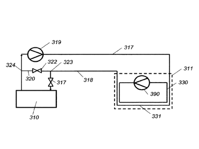
A coolant supply conduit 317 may be provided for supplying coolant from the
cooling unit 310 to
the ice-generating system 311. A coolant return conduit 318 may be provided
for returning
coolant from the ice-generating system 311 to the cooling unit 310.
5 .. A coolant pump 319 may be provided to pump the coolant between the ice-
generating system
311 and the cooling unit 310. The coolant pump 319 may be integrated in the
cooling unit 310 or
be a separate pump located along the cooling circuit. Preferably, the coolant
pump 319 is located
in the coolant supply conduit 317.
10 A coolant bypass conduit 320 may be arranged to selectively direct
coolant from the coolant
return conduit 318 into the coolant supply conduit 317 without passing through
the cooling unit
310. The coolant bypass conduit 320 may extend from a first junction 323 with
the coolant return
conduit 318 which is upstream of the cooling unit 310 to a second junction 324
with the coolant
supply conduit 317 which is downstream of the cooling unit 310.
A cooling unit valve 321 may be provided for controlling flow from the coolant
return conduit 318
into the cooling unit 310. The cooling unit valve 321 may be located in the
coolant return conduit
318 downstream of the first junction 323. A coolant bypass conduit valve 322
may be provided
for controlling flow through the coolant bypass conduit 320. The coolant
bypass conduit valve
322 may be located in the coolant bypass conduit 320. In the illustrated
example, each of the
cooling unit valve 321 and the coolant bypass conduit valve 322 are a two-way
valve, for
example a solenoid valve.
Alternatively, the cooling unit valve 321 and the coolant bypass conduit valve
322 may be
substituted for a three-way valve located at the first junction 323 which acts
to divert flow of
coolant through either the coolant return conduit 318 towards the cooling unit
310 or through the
coolant bypass conduit 320 so as to bypass the cooling unit 310.
As shown in Figure 4, the ice-generating system 311 comprises a product
conduit 330 for
containing a beverage liquor and a cooling conduit 331 which is arranged in
proximity with the
product conduit 330 to permit heat exchange between coolant in the cooling
conduit 331 and
beverage liquor in the product conduit 330. The ice-generating system 311
functions to form a
plurality of ice crystals within the beverage liquor as explained further
below.
.. The cooling conduit 331 may be fluidly connected to the coolant supply
conduit 317 to receive
coolant therefrom and also fluidly connected to the coolant return conduit 318
to deliver coolant
thereto.
CA 03142183 2021-11-29
WO 2020/239408
PCT/EP2020/062990
16
Preferably, at least a portion of the product conduit 330 and the cooling
conduit 331 extend
concentrically to one another. Preferably the cooling conduit 331 surrounds
the product conduit
330. In one example, the product conduit 330 comprises an inner plastic tube
that runs within an
outer plastic tube. The annular void external to the inner plastic tube and
within the outer plastic
tube defines the cooling conduit 331.
The product conduit 330 and the cooling conduit 331 may be arranged into a
spiral configuration.
The product conduit 330 and the cooling conduit 331 may extend for a length of
at least 5m,
preferably at least 10m. The cooling conduit 331 may be split into two or more
spiral loops, each
loop extending concentrically with a different portion of the product conduit
330. For example,
with a product conduit 330 of 10m length in a spiral configuration the cooling
conduit 331 may be
split into two 5m loops that run concentrically with, respectively, an upper
half and a lower half of
the product conduit 330. The coolant may be supplied to the loops of the
cooling conduit 331 in
parallel or series flow.
The conduits of the apparatus 300 may be configured into at least a primary
cooling circuit and a
secondary cooling circuit. The primary cooling circuit preferably comprises
the cooling unit 310,
the coolant supply conduit 317, the cooling conduit 331 and the coolant return
conduit 318. The
secondary cooling circuit preferably comprises the coolant supply conduit 317,
the cooling
conduit 331, the coolant return conduit 318 and the coolant bypass conduit 320
but does not
comprise the cooling unit 310.
The apparatus 300 may further comprise a heater 340, for example a flow
through heater,
positioned in the primary cooling circuit and/or secondary cooling circuit. In
the illustrated
example the heater 340 is located in the coolant return conduit 318 so that it
is located in a
position that is common to both the primary cooling circuit and the secondary
cooling circuit.
As shown in Figure 4, the water pre-chiller 312 is provided for supplying
chilled water to the
ingredient source section 313. The water pre-chiller 312 may contain or be
supplied with water.
For example, the water pre-chiller 312 may contain a self-contained reservoir,
such as a bottle or
tank, containing a volume of water that is replenished from time to time by
exchanging an empty
reservoir for a full reservoir. However, preferably the water pre-chiller 312
is connected to receive
water from an external source, such as mains water 347. A water filter 348 and
flow control valve
349 may be provided to condition and control the supply. The water pre-chiller
312 may be any
suitable device that can chill the incoming water down to a suitable
temperature for supply to the
ingredient source section 313. Preferably the water is chilled to a
temperature of 2-5 C. The
water pre-chiller 312 may be a phase change material (PCM) cooler or similar
device. However,
a preferred water pre-chiller 312 is illustrated schematically in Figures 6A
to 6C and utilises flow
CA 03142183 2021-11-29
WO 2020/239408
PCT/EP2020/062990
17
of coolant from the cooling unit 310. In this example, the water in the water
pre-chiller 312 is
cooled by a heat exchanger that is itself cooled by coolant from the cooling
unit 310. The heat
exchanger may be either part of the water pre-chiller 312, or may be in
thermal contact with the
water pre-chiller 312. The heat exchanger may comprises one or more blocks for
transferring
thermal energy. In the example of Figure 6A, a first block 350, preferably of
aluminium,
comprises a first conduit 353 through which coolant from the cooling unit 210
flows. Multiple first
conduits may be provided. A second block 351, forming part of the water pre-
chiller 312 and also
preferably of aluminium, comprises a second conduit 354 through which the
water in the water
pre-chiller 312 flows. Multiple second conduits may be provided. Water in the
second conduit 354
is cooled by heat transfer through the second block 351 and the first block
350. A single integral
block may be provided instead of a first block 350 and a second block 352. The
second conduit
354 may take a circuitous route through the second block 351 and/or water may
be passed
through the second conduit 354 multiple times to be chilled in successive
passes. Further, the
second conduit 354 may form a reservoir that holds stationary water for
chilling as opposed to
operating as a flow-through chiller.
As shown most clearly in Figure 4, the cooling unit 310 may supply coolant to
an ice-generating
cooling circuit which supplies coolant from the cooling unit 310 to the ice-
generating system 311
and a pre-chiller cooling circuit for supplying coolant from the cooling unit
310 to the water pre-
chiller 312. Beneficially, a single cooling unit 310 can provide the coolant
for both the ice-
generating cooling circuit and the pre-chiller cooling circuit.
The pre-chiller cooling circuit may comprise a secondary coolant supply
conduit 376 for
supplying coolant from the cooling unit 310 to the water pre-chiller 312. A
secondary coolant
return conduit 379 may be provided for returning coolant from the water pre-
chiller 312 to the
cooling unit 310.
A secondary coolant pump 377 may be provided to pump the coolant between the
cooling unit
310 and the water pre-chiller 312. The secondary coolant pump 377 may be
integrated in the
cooling unit 310 or be a separate pump located along the secondary cooling
circuit. Preferably,
the secondary coolant pump 377 is located in the secondary coolant supply
conduit 376.
As shown in Figure 4, the ingredient source section 313 comprises a beverage
concentrate
reservoir 360 containing a beverage concentrate. Preferably, it also comprises
a sweetener
concentrate reservoir 361 containing a sweetener concentrate. The beverage
concentrate
contains soluble coffee or tea solids. The sweetener concentrate contains a
freezing point
suppressant which may be a food-safe soluble ingredient such as a salt, an
alcohol, a sugar
and/or sugar replacement, ice-structuring proteins or combinations of two or
more thereof. It is
CA 03142183 2021-11-29
WO 2020/239408
PCT/EP2020/062990
18
most preferred that the freezing-point suppressant is itself a sweetener, such
as a polyol or a
sugar or a mixture thereof. The most preferred freezing point suppressant is
sugar or a sugar
replacement, preferably sucrose and/or fructose and/or polydextrose. Suitable
sugars include
mono and disaccharides, preferably, sucrose, fructose, and/or glucose.
Optionally, the ingredient source section 313 may comprise two reservoirs
containing, preferably,
the same ingredient, wherein the apparatus is programmed to switch supply from
a first of the
two reservoirs to a second of the two reservoirs when the first of the two
reservoirs is emptied. In
this way a service-ready time of the apparatus may be increased. For example,
the reservoir 360
and the reservoir 361 in the example of Figure 4 may, optionally, be
configured to both contain a
same beverage concentrate-sweetener concentrate mix.
A first pre-mixer 362 may be provided for mixing the beverage concentrate
supplied from the
beverage concentrate reservoir 360 with water supplied from the water pre-
chiller 312. Likewise,
a second pre-mixer 363 may be provided for mixing the sweetener concentrate
supplied from the
sweetener concentrate reservoir 361 with water supplied from the water pre-
chiller 312. The
water supply to the first pre-mixer 362 and/or the second pre-mixer 363 may be
controlled by
supply valves 369.
The ingredient source section 313 may further comprise a mixing chamber 364
for mixing an
output from the first pre-mixer 362 with an output from the second pre-mixer
363 (where present)
to form a beverage liquor. Water may be supplied to the mixing chamber 364
from the water pre-
chiller 312 in addition to, or in place of, supplying water to the first pre-
mixer 362 and the second
pre-mixer 363. The mixing chamber 364 may comprise an agitator for assisting
in the mixing of
the beverage liquor and also for recirculating beverage liquor standing in the
mixing chamber
364. The agitator may comprise a rotating blade, paddle, whisk or similar
device. Additionally or
alternatively, the agitator may comprise a recirculation of the beverage
liquor from an output of
the mixing chamber 364 back into the mixing chamber 364 to create turbulence
and mixing of the
beverage liquor within the mixing chamber 364. A recirculation pump and
recirculation conduit
may be provided to affect such agitation.
The beverage liquor may then be supplied onwards to the ice-generating system
311 as
explained further below.
The beverage concentrate in the beverage concentrate reservoir 360 may be a
powder but is
preferably a liquid concentrate. Likewise, the sweetener concentrate in the
sweetener
concentrate reservoir 361 may be a powder but is preferably a liquid
concentrate.
CA 03142183 2021-11-29
WO 2020/239408
PCT/EP2020/062990
19
The beverage concentrate reservoir 360 and the sweetener concentrate reservoir
361 may each
comprise a chamber, hopper or similar that is manually filled with concentrate
by an operator, for
example by opening a bulk container of concentrate and pouring the concentrate
into the
chamber or hopper. However, it is preferred that the beverage concentrate
reservoir 360 and the
sweetener concentrate reservoir 361 each comprise an exchangeable supply pack
which may be
coupled with and decoupled from the apparatus 300. The use of exchangeable
supply packs
may improve the ease and cleanliness of use of the apparatus 300. Various
types of
exchangeable supply pack may be used including, but not limited to, a pouch,
capsule, cartridge,
box, bag-in-box or similar. The exchangeable supply pack may be sealed prior
to coupling with
the apparatus 300. Means for opening the exchangeable supply pack may be
integrated in the
exchangeable supply pack or in the apparatus 300. The exchangeable supply pack
may be
opened automatically during coupling of the exchangeable supply pack to the
apparatus 300. A
preferred option for the exchangeable supply pack is a Promesso rtm
exchangeable supply pack
available from Koninklijke Douwe Egberts B.V. Such an exchangeable supply pack
may include
a container for holding the concentrate and a doser having an outlet. The
doser is arranged for
supplying the concentrate from the container to the outlet of the doser in a
dosed manner. The
doser may include a pump assembly that enables the pumping of a desired dosage
of the
concentrate from the container out of the outlet and into the pre-mixer 362,
363.
The exchangeable supply pack and the apparatus may be mechanically
connectable. When
connected, the outlet of the doser is brought in fluid communication with the
respective pre-mixer
362, 363 and a drive shaft (not shown) of the apparatus 300 may be arranged
for transmitting
torque from the apparatus 300 to the doser such that when the drive shaft is
activated
concentrate is supplied from the outlet of the doser into the pre-mixer 362,
363.
As shown in Figure 8, each pre-mixer 362, 363 may be provided with a pre-mixer
inlet 370 for
receiving concentrate from the doser of the exchangeable supply pack. The pre-
mixer inlet 370
may be located towards a top of the pre-mixer 362, 363 such that the
concentrate may flow from
the outlet of the doser into the pre-mixer 362, 363 substantially under the
influence of gravity.
A pre-mixer outlet 372 may be provided for discharging the output into the
mixing chamber 364
and a conduit 371 may extend between the pre-mixer inlet 370 and the pre-mixer
outlet 372.
Further, each pre-mixer 362, 363 may comprise a water inlet opening 373 into
the conduit 371
for feeding into the pre-mixer 362, 363 water supplied from the water pre-
chiller 312. Preferably,
the water inlet opening 373 is orientated to jet inflowing water towards the
pre-mixer inlet 370 to
thereby flush the outlet of the doser of the exchangeable supply pack, which
in use is coupled to
the pre-mixer inlet 370.
CA 03142183 2021-11-29
WO 2020/239408
PCT/EP2020/062990
It is preferred to maintain the beverage concentrate in a chilled state to
maintain freshness and
improve shelf-life. In order to achieve this, it is preferred that the water
pre-chiller 312 and/or the
heat exchanger is in thermal contact with the beverage concentrate reservoir
360. The water pre-
chiller 312 and/or the heat exchanger may also beneficially be in thermal
contact with the pre-
5 mixer 362 and/or mixing chamber 364.
In one example, the beverage concentrate reservoir 360 is in contact with the
first block 350
and/or the second block 351. Optionally the first block 350 and/or the second
block 351 are in
face-to-face contact with a face of the beverage concentrate reservoir 360.
The use of
10 exchangeable supply packs that are parallelepiped in shape may be
beneficial for this as they
provide a relatively large surface area to make contact with the first block
350 and/or the second
block 351. In the arrangement of Figure 6A, a beverage concentrate reservoir
360 in the form of
an exchangeable supply pack C is positioned alongside, and in thermal contact
with, the water
pre-chiller 312, in particular the second block 351 thereof. A side face of
the exchangeable
15 supply pack C is preferably in face-to-face contact with a side face of
the second block 351. In
the alternative arrangement of Figure 6B, the exchangeable supply pack C is
positioned above,
and in thermal contact with, the water pre-chiller 312, in particular the
first block 350 thereof. A
bottom face of the exchangeable supply pack C is preferably in face-to-face
contact with a top
face of the first block 350. In the further alternative arrangement of Figure
6C, the exchangeable
20 supply pack C is positioned above, and in thermal contact with, the
water pre-chiller 312, in
particular the second block 351 thereof. A bottom face of the exchangeable
supply pack C is
preferably in face-to-face contact with a top face of the second block 351.
Preferably, the sweetener concentrate reservoir 361 is thermally isolated from
the water pre-
chiller 312 and/or heat exchanger. This may be beneficial to prevent
crystallisation of the
ingredients of the sweetener concentrate. Preferably the temperature of the
sweetener
concentrate reservoir 361 is maintained at greater than 10 C. For example, in
the arrangements
of Figure 6A to 6C, the sweetener concentrate reservoir 361 in the form of an
exchangeable
supply pack S is separated from, i.e. out of thermal contact with, the water
pre-chiller 312.
Optionally, thermal insulation material may be interposed between the
sweetener concentrate
reservoir 361 and the water pre-chiller 312.
An output 380 of the mixing chamber 364 may supply the beverage liquor to the
ice-generating
system 311 via a beverage product circuit which may comprise one or more
conduits and one or
more product supply valves 366a, 366b. The beverage liquor is preferably
aerated prior to
reaching the ice-generating system 311. An air pump 367 may inject air under
control of an air
supply valve 368 into the conduit containing the beverage liquor before it
reaches the one of
more product supply valves 366a, 366b. The air may be injected through one or
more gas
CA 03142183 2021-11-29
WO 2020/239408
PCT/EP2020/062990
21
injection orifices. In order to favour the production of a fine distribution
of small bubbles the flow
of the beverage liquor with the added gas may be pumped through a static mixer
or one or more
constricting orifices. By way of example, a 1mm gas injection orifice might
produce 5mm bubbles
in the conduit. The passing of these bubbles through an orifice of less than 1
mm fractures these
bubbles into bubbles smaller than 1mm each. This fine bubble structure aids
the ice stability and
the creaminess of the final beverage. The air is preferably added at a
pressure of up to 10 Bar,
preferably from 3 to 4 Bar. The beverage liquor may be pumped out of the
mixing chamber 364
and through the product supply valves 366a, 366b by means of an upstream
product pump 365
as shown in Figure 4.
The one or more product supply valves 366a, 366b may connect to the product
conduit 330 of
the ice-generating system 311. The one or more product supply valves 366a,
366b may
comprise a first product supply valve 366a and a second product supply valve
366b. The product
conduit 330 may form a loop to allow the beverage liquor to circulate.
Beverage liquor may be
input into the product conduit 330 through one or more beverage liquor inlets.
A first beverage
liquor inlet 394 may be provided which may be connected to the first product
supply valve 366a
by a first product supply conduit 375a of the beverage product circuit. A
second beverage liquor
inlet 395 may be provided which may be connected to the second product supply
valve 366b by
a second product supply conduit 375b of the beverage product circuit.
Beverage liquor containing the plurality of ice crystals may be discharged
from the product
conduit 330 through an outlet 393 that supplies the beverage dispensing outlet
303. Preferably,
only a single outlet 393 is provided. Preferably, the volume and/or pressure
of the beverage
liquor within the product conduit 330 is maintained within set limits, and
preferably substantially
constant and preferably at around 2 bar. This may be achieved by ensuring that
the total volume
of beverage liquor input to the product conduit 330 through the one or more
beverage liquor
inlets 394, 395 equals the volume of the beverage liquor discharged through
the outlet 393.
The product conduit 330 comprises a primary product pump 390 for circulating
the beverage
liquor around the product conduit 330. An upstream pressure sensor 391 and a
downstream
pressure sensor 392, as shown in Figures 7A and 7B, may be located on either
side of the
primary product pump 390 to sense the differential pressure across the primary
product pump
390. This differential pressure may be used to calculate, infer or estimate
the ice/liquid ratio of
the beverage liquor.
Figure 7A illustrates an example where only a first beverage liquor inlet 394
is provided. A
quantity of relatively warm beverage liquor 397 is input through first
beverage liquor inlet 394 and
is circulated clockwise (as viewed in Figure 7A) at the same time as already
present and
CA 03142183 2021-11-29
WO 2020/239408
PCT/EP2020/062990
22
relatively cold beverage liquor 396 containing a plurality of ice crystals is
discharged through the
outlet 393. As the relatively warm beverage liquor 397 passes the primary
product pump 390 a
change in the differential pressure between the upstream pressure sensor 391
and the
downstream pressure sensor 392 is detected by the controller which acts to
increase the rate of
.. cooling of the product conduit 330, as discussed further below, to cool the
relatively warm
beverage liquor 397 to form the desired ice/water ratio.
A potential disadvantage of the arrangement of Figure 7A is that frozen
blockages may occur
where the increased rate of cooling commanded by the controller imparts
further cooling to the
.. relatively cold beverage liquor 396 still circulating in the product
conduit 330.
Thus, Figure 7B presents an improved arrangement wherein at least the first
beverage liquor
inlet 394 and the second beverage liquor inlet 395 are used. The first
beverage liquor inlet 394
and the second beverage liquor inlet 395 are distributed along the product
conduit 330. For
example, the loop of the product conduit 330 may be considered to have a
length of X, and the
second beverage liquor inlet 395 may be located between 0.4X and 0.6X along
the loop of the
product conduit 330 from the first beverage liquor inlet 394. For example, in
the case of a product
conduit 330 of length X=10m the second beverage liquor inlet 395 would be
located between 4m
(10m x 0.4) and 6m (10m x 0.6) along the loop of the product conduit 330 from
the first beverage
liquor inlet 394. More preferably, the second beverage liquor inlet 395 may be
located halfway
around the loop of the product conduit 330 from the first beverage liquor
inlet 394, i.e. at 0.5X.
Optionally, third and/or fourth, etc. beverage liquor inlets may be provided.
These may preferably
be evenly distributed around the loop of the product conduit 330, i.e. at OX,
0.33X and 0.67X
where three beverage liquor inlets are provided; at OX, 0.25X. 0.50X and 0.75
X where four
.. beverage liquor inlets are provided, etc.
Inputting the relatively warm beverage liquor 397 through at least two
beverage liquor inlets is
beneficial as it provides a more even distribution of the relatively warm
beverage liquor 397 in the
relatively cold beverage liquor 396 as shown schematically in Figure 7B. This
may help or reduce
.. or eliminate frozen blockages occurring. Further benefit can be achieved by
configuring and
arranging for the input of beverage liquor into the product conduit 330 to be
alternated, preferably
relatively quickly, between the at least two beverage liquor inlets such that
'chunks' of relatively
warm beverage liquor 397 are input into the flow of relatively cold beverage
liquor 396 such that
each chunk is bounded on either side by relatively cold beverage liquor 396.
This may
.. beneficially create an even more even distribution of the relatively warm
beverage liquor 397 in
the relatively cold beverage liquor 396. This may reduce or eliminate frozen
blockages occurring.
In addition, using this arrangement may mean that the controller does not need
to switch rapidly
from an aggressive cooling mode to a non-cooling mode. Further the proximity
of the relatively
CA 03142183 2021-11-29
WO 2020/239408
PCT/EP2020/062990
23
cold beverage liquor 396 to the relatively small volume of each chunk of
relatively warm
beverage liquor 397 helps to cool more efficiently the relatively warm
beverage liquor 397.
This configuration may be achieved by arranging the first product supply valve
366a for
controlling flow of beverage liquor to the first beverage liquor inlet 394 and
the second product
supply valve 366b for controlling flow of beverage liquor to the second
beverage liquor inlet 395
as noted above. Further, the controller may be configured and arranged to
control actuation of
the first product supply valve 366a and the second product supply valve 366b
to alternate the
input of beverage liquor into the product conduit 330 through the first
product supply valve 366a
and the second product supply valve 366b by cycling the first product supply
valve 366a and the
second product supply valve 366b between a first configuration where the first
product supply
valve 366a is open and the second product supply valve 366b is closed and a
second
configuration where the first product supply valve 366a is closed and the
second product supply
valve 366b is open. Preferably the cycle time may be such as to obtain a valve
open time of 0.3
.. to 0.8 seconds, preferably 0.4 to 0.6 seconds, more preferably 0.5 seconds
for each cycle.
Preferably, the cycling of the first product supply valve 366a and the second
product supply valve
366b includes an overlap period in each cycle where both the first product
supply valve 366a and
the second product supply valve 366b are open to help ensure a constant inflow
into the product
conduit 330.
A non-limiting example of use of the apparatus 300 will now be described. A
beverage
concentrate reservoir 360 in the form of a Promesso rim exchangeable supply
pack containing a
beverage concentrate containing soluble coffee solids and a sweetener
concentrate reservoir
361 in the form of a Promesso rim exchangeable supply pack containing a
sweetener concentrate
.. are installed in the apparatus 300, mechanically coupled to the respective
first pre-mixer 362 and
second pre-mixer 363.
Water supplied to the water pre-chiller 312 is chilled to a temperature of 2-5
C by coolant flowing
through the pre-chiller cooling circuit, in particular wherein coolant is
pumped by the secondary
coolant pump 377 from the cooling unit 310 along the secondary coolant supply
conduit 376,
through the first conduit 353 of the heat exchanger and then back to the
cooling unit 310 along
secondary coolant return conduit 379. Flow of the coolant around the pre-
chiller cooling circuit is
controlled by the controller. As will be appreciated by those skilled in the
art, sensors and/or
meters, for example flow meters and temperature sensors, may be provided to
provide the
necessary data inputs to the controller to permit flow and/or temperature
control of the pre-chiller
cooling circuit to be achieved.
CA 03142183 2021-11-29
WO 2020/239408
PCT/EP2020/062990
24
When demanded by the controller, a dose of beverage concentrate is dosed from
the beverage
concentrate reservoir 360 into the first pre-mixer 362 through the pre-mixer
inlet 370 where it is
mixed and diluted with water that is injected through the water inlet opening
373. This water is
supplied from the water pre-chiller 312 by the controller opening the
respective supply valve 369.
The diluted beverage concentrate passes along the conduit 371 and is
discharged through the
pre-mixer outlet 372 into the mixing chamber 364.
If required by the beverage being dispensed, a dose of sweetener concentrate
may also be
dosed, preferably simultaneously, from the sweetener concentrate reservoir 361
into the second
pre-mixer 363 through the pre-mixer inlet 370 where it is mixed and diluted
with water that is
injected through the water inlet opening 373. As above, this water is supplied
from the water pre-
chiller 312 by the controller opening the respective supply valve 369. The
diluted sweetener
concentrate passes along the conduit 371 and is discharged through the pre-
mixer outlet 372
into the mixing chamber 364.
The diluted beverage and sweetener concentrates are mixed together in the
mixing chamber 364
by the agitator to form the beverage liquor.
When demanded by the controller, beverage liquor from the mixing chamber 364
is supplied to
the ice-generating system 311 through the first product supply conduit 375a
and the second
product supply conduit 375b by operation of the first product supply valve
366a and the second
product supply valve 366b. The beverage liquor is aerated prior to reaching
the ice-generating
system 311. The air pump 367 injects air under control of the air supply valve
368 into the
conduit containing the beverage liquor before it reaches the first product
supply valve 366a and
the second product supply valve 366b.
As illustrated schematically in Figure 7B, the controller controls actuation
of the first product
supply valve 366a and the second product supply valve 366b to alternate the
input of beverage
liquor into the product conduit 330 through the first product supply valve
366a and the second
product supply valve 366b by cycling the first product supply valve 366a and
the second product
supply valve 366b between the first configuration and the second configuration
with a cycle time
of 0.3 to 0.8 seconds, preferably 0.4 to 0.6 seconds, more preferably 0.5
seconds for each cycle.
Preferably, the cycling of the first product supply valve 366a and the second
product supply valve
366b includes an overlap period in each cycle where both the first product
supply valve 366a and
the second product supply valve 366b are open to help ensure a constant inflow
into the product
conduit 330. Consequently, the beverage liquor is input into the product
conduit 330 from at least
two locations as 'chunks' of relatively warm beverage liquor 397 such that
each chunk is
bounded on either side by relatively cold beverage liquor 396.
CA 03142183 2021-11-29
WO 2020/239408
PCT/EP2020/062990
The relatively warm beverage liquor 397 circulates in the product conduit 330
where it is cooled
by the coolant flowing in the cooling conduit 331 and preferably also by the
already present
relatively cold beverage liquor 396 to form a plurality of ice crystals in the
aerated beverage
5 liquor.
Simultaneously, aerated beverage liquor that already contains a plurality of
ice crystals is
discharged out of the product conduit 330 through the single outlet 393
onwards to the beverage
dispensing outlet 303 where it is dispensed into the glass 307.
As shown in Figure 5B, the coolant flowing in the cooling conduit 331 may be
in a direction that
opposes the flow of beverage liquor in the product conduit 330.
When active cooling of the beverage liquor in the product conduit 330 is
required ¨ for example,
because the ice/water ratio as sensed by the upstream pressure sensor 391 and
downstream
pressure sensor 392 is not at a desired level ¨ the controller switches the
ice-generating system
311 to the primary mode wherein the coolant is circulated around the cooling
unit 310, the
coolant supply conduit 317, the cooling conduit 331 and the coolant return
conduit 318. By
passing the coolant through the cooling unit 310 in the primary mode the
coolant is cooled and
.. so active cooling of the beverage liquor is achieved. Beneficially, in the
primary mode coolant
may flow continuously around the primary cooling circuit and is not required
to become
stationary.
When active cooling of the beverage liquor in the product conduit 330 is not
required ¨ for
.. example, because the ice/water ratio as sensed by the upstream pressure
sensor 391 and
downstream pressure sensor 392 is at the desired level ¨ the controller
switches the ice-
generating system 311 to the secondary mode wherein the coolant is circulated
around the
secondary cooling circuit comprising the coolant supply conduit 317, the
cooling conduit 331, the
coolant return conduit 318 and the coolant bypass conduit 320. In particular,
the secondary
cooling circuit does not comprise the cooling unit 310 so the coolant is not
subjected to any
additional cooling. This allows the coolant to gradually warm up as it
circulates around the
secondary cooling loop. Beneficially, in the secondary mode coolant may flow
continuously
around the secondary cooling circuit and is not required to become stationary.
This method is in contrast to the prior art arrangement of W02014/135886,
shown schematically
in Figure 5B. In that arrangement, when active cooling of the beverage liquor
in the cooling
conduit 108 is not required the valve 24 is shut to prevent flow of coolant
through cooling conduit
108. Valve 23 is opened to circulate the coolant via the coolant bypass loop
and through the
CA 03142183 2021-11-29
WO 2020/239408
PCT/EP2020/062990
26
coolant refrigeration unit 22 using pump 19. However, coolant in the cooling
conduit 108 remains
stationary.
Thus, the present apparatus 300, system and method permit the preparation of
an ice-containing
tea or coffee beverage, which is also preferably aerated. The appearance of
the beverage which
is produced will depend on the ice-fraction and the overrun of the beverage. A
beverage with a
high overrun, such as 100% and a low ice-fraction, such as 10 to 20%, may
resemble a
homogeneous light brown foam and may retain this form and stability for upward
of 10 minutes.
In practice the ice is well insulated and melts slowly. Eventually an
underlying coffee or tea layer
may form, but this may typically take at least 30 minutes. Preferably no
separate water layer
forms, as would be seen in a beverage made from coarse ice-crystals. In a
beverage with
coarser ice-crystals, these typically migrate to the top as they are least
dense and then melt
without the beverage solids being present.
A beverage with a lower overrun, such as 25% and with a higher ice fraction,
such as 30%, may
form an initial thicker foam layer on a darker beverage layer. However, the
whole structure will
have an even distribution of ice and will not form a separate water layer.
Instead it may resemble,
albeit with less separation, the classic beverage Guinness rtm appearance of a
dark liquor with a
foamed head and demonstrates a storm-cloud settling effect. The foam persists
in part because
it is stabilised by the fine ice-crystals distributed therein.
Figure 9 illustrates a further embodiment of apparatus 300 according to the
present disclosure. In
the following description only the differences between this embodiment and the
preceding
embodiments will be described. It will be understood by the skilled reader
that in all other
respects the apparatus 300 may be configured and function as described above
in the preceding
embodiments.
As in the previous embodiments the apparatus 300 of Figure 9 may take the form
of a mobile
point-of-sale unit which may be configured to be operated by a barkeeper or
similar server or
may be configured as a self-serve machine. The apparatus 300 may comprise a
first beverage
dispensing outlet 303a for dispensing a first beverage and a second dispensing
outlet 303b for
dispensing a second beverage. In the illustrated example, the beverage
dispensing outlets 303a,
303b each take the form of a beverage nozzle 304a, 304b, such as a post-mix
style head. The
beverage dispensing outlets 303a, 303b may both be provided for example on a
single font or, as
illustrated in Figure 9, separately on two fonts 305a, 305b each of which is
mounted to the top
surface 306 of the main housing 301.
CA 03142183 2021-11-29
WO 2020/239408
PCT/EP2020/062990
27
The apparatus 300 may be configured for preparing an ice-containing tea or
coffee beverage,
preferably an aerated ice-containing tea or coffee beverage, which may be
dispensed via the first
beverage dispensing outlet 303a. The apparatus 300 may in addition be
configured for preparing
another beverage of a different type which may be dispensed via the second
beverage
dispensing outlet 303b. The beverage of the different type may be for example
a beverage not
containing ice, for example a tea or coffee beverage not containing ice. The
beverage of the
different type may for example be an aerated tea or coffee beverage and
preferably a cooled and
aerated tea or coffee beverage.
Figure 10 illustrates an example of a flow schematic for the apparatus 300
suitable to achieve
this configuration. The flow schematic is the same as that of Figure 4 except
for the following
points.
The beverage supplied to the second beverage dispensing outlet 303b by-passes
the ice-
generating system 311 such that ice crystals are not formed in the beverage
prior to
dispensation. Instead the beverage may consist of or comprise the beverage
liquor that is output
from the mixing chamber 364. As shown in Figure 10, an additional product
supply valve 366c
may be provided to selectively direct the beverage liquor to the second
dispensing outlet 303b
via a beverage conduit 398. As in the above embodiments, this beverage liquor
may optionally
be aerated by the air pump 367. The upstream product pump 365 may drive the
flow of beverage
liquor to the second beverage dispensing outlet 303b.
In operation of the apparatus 300 an ice-containing beverage may be dispensed
from the first
beverage dispensing outlet 303a and a non-ice-containing beverage may be
dispensed from the
second beverage dispensing outlet 303b. Advantageously, the same beverage
liquor output from
the mixing chamber 364 may be used to supply both beverage dispensing outlets
303a, 303b.
The apparatus 300 may additionally or alternatively be adapted compared to the
preceding
embodiments by maintaining the sweetener concentrate reservoir 361 in a
chilled state within the
apparatus 300. It has been found that chilling of the sweetener concentrate
reservoir 361 is not
always required to prevent ice crystallisation, in particular in situations
where the expected usage
rate of the sweetener concentrate means that the sweetener concentrate
reservoir 361 will be
replaced every 5 to 10 days. Advantageously chilling the sweetener concentrate
reservoir 361
can provide improved efficiency when cooling the resulting beverage liquor
containing the
sweetener concentrate, reduce the risk of microbial growth and reduce the
length of conduits
required to connect the sweetener concentrate reservoir 361 to a remainder of
the apparatus
300. Further, maintaining both the beverage concentrate reservoir 360 and the
sweetener
concentrate reservoir 361 in a chilled state may allow a simplified component
layout within the
CA 03142183 2021-11-29
WO 2020/239408
PCT/EP2020/062990
28
housing 301. For example, a separate uncooled chamber is not required for the
sweetener
concentrate reservoir 361 and both reservoirs 360, 361 can be stored in the
same compartment.
In a first example configuration the sweetener concentrate reservoir 361 may
be placed in
thermal contact with the water pre-chiller 312 and/or the heat exchanger
and/or the beverage
concentrate reservoir 360. For example, the sweetener concentrate reservoir
361 in the form of
the exchangeable supply pack S may be positioned alongside, and in thermal
contact with, the
water pre-chiller 312, in particular the first block 350 and/or second block
351 thereof.
.. In a second example configuration the beverage concentrate reservoir 360
and the sweetener
concentrate reservoir 361 may be placed in a refrigerated compartment of the
apparatus. The
refrigerated compartment may be cooled by the water pre-chiller 312 and/or the
heat exchanger
and/or by another refrigeration means.
Although preferred embodiments of the present disclosure have been described
herein in detail,
it will be understood by those skilled in the art that variations may be made
thereto without
departing from the scope of the appended claims.