Note: Descriptions are shown in the official language in which they were submitted.
CUT MATERIAL
CROSS-REFERENCE TO RELATED APPLICATIONS
[0001] This application claims priority from United States Patent
Application No.
62/856,502 filed June 3, 2019.
TECHNICAL FIELD
[0002] This disclosure relates generally to sublimation printing
components,
apparatuses, systems and methods.
BACKGROUND
[0003] This section provides background information related to the
present
disclosure and is not necessarily prior art.
[0004] In general, sublimation is a chemical process where a solid
material turns
into a gas without going through a liquid stage. Sublimation printing, also
known as dye
sublimation printing, is a popular printing method for transferring images
onto suitable
materials.
[0005] While known sublimation printing components, apparatuses,
systems and
methods have proven to be acceptable for various applications, such
sublimation printing
components, apparatuses, systems and methods are nevertheless susceptible to
improvements that may enhance their overall performance and cost. Therefore, a
need
exists to develop improved sublimation printing components, apparatuses,
systems and
methods that advance the art.
1
Date Recue/Date Received 2023-01-25
CA 03142429 2021-11-30
WO 2020/247368 PCT/US2020/035696
SUMMARY
[0006] This section provides a general summary of the disclosure, and
is not a
comprehensive disclosure of its full scope or all of its features.
[0007] Implementations of the present disclosure relate generally to
cut material
systems, methods, and apparatus. In particular, the present disclosure relates
to pre-
mounted ink sublimation cut materials. For example, in one implementation of
the present
disclosure, a cut material includes an infusible ink layup, a laminate layer,
and a backing
layer. In such an implementation, the laminate layer is disposed between the
infusible ink
layup and the backing layer.
[0008] Implementations of the disclosure may include one or more of the
following optional features. In some implementations, the infusible ink layup
comprises
an infusible sublimation material layer and a sublimation material carrier
layer. The
laminate may be disposed against the sublimation material carrier layer. In
some
implementations, the cut material includes an adhesive layer disposed between
the
backing layer and the laminate layer. The adhesive layer may removably secure
the
backing layer to the laminate layer.
[0009] In some implementations, the cut material includes a print
layer disposed
between the backing layer and the laminate layer. In some implementations, the
cut
material includes an adhesive layer disposed between the print layer and the
laminate
layer. The print layer and the backing layer may be removably secured to the
laminate
layer via the adhesive layer.
[0010] In some implementations, the cut material includes a print
layer. The
backing layer may be disposed between the print layer and the laminate layer.
In some
implementations, the cut material includes an adhesive layer disposed between
the
backing layer and the laminate layer. The adhesive layer may removably secure
the
backing layer to the laminate layer.
[0011] In one implementation of the present disclosure, a cut
material includes an
infusible ink layer, a paper layer, a laminate layer, and a backing layer. In
such an
implementation, the paper layer is disposed between the infusible ink layer
and the
laminate layer and the laminate layer is disposed between the paper layer and
the backing
layer.
2
CA 03142429 2021-11-30
WO 2020/247368 PCT/US2020/035696
[0012] In one implementation of the present disclosure, a method of
infusing ink
into an article, includes: providing a cut material comprising an ink
sublimation layup
and a backing layer, the ink sublimation layup comprising sublimation ink;
performing a
cutting operation on the cut material; removing a portion of the ink
sublimation layup
from the backing layer of the cut material; placing the ink sublimation layup
against an
article; and sublimating the sublimation ink into the article.
[0013] Another aspect of the disclosure provides a cut material. The
cut material
may include an infusible sublimation material layer, a backing layer, a
sublimation
material carrier layer disposed between the infusible sublimation material
layer and the
backing layer, and a laminate layer disposed between the sublimation material
carrier
layer and the backing layer.
[0014] This aspect may include one or more of the following optional
features.
In some implementations, the laminate layer comprises pulp and calcium
carbonate.
[0015] In some implementations, the laminate layer is between about
40 .. 60
g/m2.
[0016] In some implementations, the laminate layer comprises a
silicone oil
coating disposed between the laminate layer and the backing layer.
[0017] In some implementations, the backing layer comprises PET.
[0018] In some implementations, a thickness of the backing layer is
between
_____ about 40 60 gm.
[0019] In some implementations, the cut material comprises an
adhesive layer
disposed between the laminate layer and the backing layer. The adhesive layer
may
comprise a pressure sensitive adhesive.
[0020] Another aspect of the disclosure provides a method of infusing
ink. The
method may comprise cutting a cut material. The cut material may comprise an
ink
sublimation layup and a backing layer. The ink sublimation layup may comprise
sublimation ink. The method may also include removing a first portion of the
ink
sublimation layup from the backing layer of the cut material. The method may
further
include placing the cut material against an article. The method may also
include
sublimating the sublimation ink of a second portion of the sublimation ink
layup into the
article.
3
CA 03142429 2021-11-30
WO 2020/247368 PCT/US2020/035696
[0021] This aspect may include one or more of the following optional
features.
In some implementations, the cut material further comprises a laminate layer
disposed
between the ink sublimation layup and the backing layer. Cutting the cut
material may
comprise cutting through the ink sublimation layup but not through the backing
layer.
[0022] In some implementations, the method includes removing a portion of
the
laminate layer from the backing layer after cutting the cut material. The
portion of the
laminate layer being removed from the backing layer may correspond in position
with,
and be removably secured to, the first portion of the ink sublimation layup
removed from
the backing layer.
[0023] Each of the above independent implementations of the present
disclosure,
and those implementations described in the detailed description below, may
include any
of the features, options, and possibilities set out in the present disclosure
and figures,
including those under the other independent implementations, and may also
include any
combination of any of the features, options, and possibilities set out in the
present
disclosure and figures.
[0024] Additional features and advantages of exemplary
implementations of the
present disclosure will be set forth in the description which follows, and in
part will be
obvious from the description, or may be learned by the practice of such
exemplary
implementations. The features and advantages of such implementations may be
realized
and obtained by means of the instruments and combinations particularly pointed
out in
the appended claims. These and other features will become more fully apparent
from the
following description and appended claims or may be learned by the practice of
such
exemplary implementations as set forth hereinafter.
[0025] The details of one or more implementations of the disclosure
are set forth
in the accompanying drawings and the description below. Other aspects,
features, and
advantages will be apparent from the description and drawings, and from the
claims.
DESCRIPTION OF DRAWINGS
[0026] The drawings described herein are for illustrative purposes
only of
.. selected configurations and not all possible implementations, and are not
intended to limit
the scope of the present disclosure.
4
CA 03142429 2021-11-30
WO 2020/247368 PCT/US2020/035696
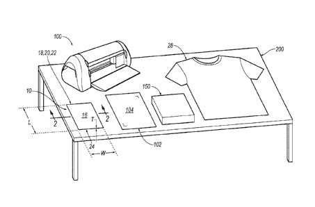
[0027] FIG. 1 is a perspective view of a sublimation system including
a layup
sheet, a processing device, a cutting mat, a heating device, and a workpiece
arranged upon
a table, according to the principles of the present disclosure.
[0028] FIG. 2 is a cross-sectional view of the layup sheet according
to line 2-2 of
FIG. 1.
[0029] FIG. 2' is another cross-sectional view of the layup sheet of
FIG. 2
arranged in a partially separated orientation, according to the principles of
the present
disclosure.
[0030] FIG. 3 is another perspective view of the system of FIG. 1
including the
layup sheet arranged upon the cutting mat and both being disposed within the
processing
device.
[0031] FIG. 4 is a perspective view of the layup sheet arranged upon
the cutting
mat that are both disposed within the processing device according to arrow 4
of FIG. 3.
[0032] FIG. 5 is a cross-sectional view according to line 5-5 of FIG.
4.
[0033] FIG. 6 is another perspective view according to FIG. 4 illustrating
the
layup sheet in a post-cut operation performed by the processing device.
[0034] FIG. 7 is a cross-sectional view according to line 7-7 of FIG.
6.
[0035] FIG. 8 is another perspective view according to FIG. 6
illustrating the
layup sheet in a post-cut-and-peeled configuration.
[0036] FIG. 9 is a cross-sectional view according to line 9-9 of FIG. 8.
[0037] FIG. 10 is another perspective view of the system of FIG. 1
including the
heating device arranged upon the cut-and-peeled layup sheet that is arranged
upon the
workpiece.
[0038] FIG. 11 is a cross-sectional view according to line 11-11 of
FIG. 10
illustrating a sublimation material layer of the layup sheet arranged in a pre-
sublimated
orientation relative the workpiece.
[0039] FIG. 11' is another cross-sectional view according to FIG. 11
illustrating
the sublimation material layer of the layup sheet arranged in a post-
sublimated orientation
that is sublimated into the workpiece.
[0040] FIG. 12A is an enlarged view according to line 12A of FIG. 11.
[0041] FIG. 12B is another enlarged view according to FIG. 12A.
5
CA 03142429 2021-11-30
WO 2020/247368 PCT/US2020/035696
[0042] FIG. 12C is another enlarged view according to FIG. 12B.
[0043] FIG. 12D is another enlarged view according to FIG. 12C and
also
according to line 12D of FIG. 11'.
[0044] FIG. 13 is a flow-chart illustrating a method associated with
the system of
FIG. 1, according to the principles of the present disclosure
[0045] FIG. 14 is a cross-sectional view of another layup sheet
according to the
principles of the present disclosure.
[0046] FIG. 15 is a cross-sectional view of another layup sheet
according to the
principles of the present disclosure.
[0047] FIG. 16 is a cross-sectional view of another layup sheet according
to the
principles of the present disclosure.
[0048] FIG. 17 is a cross-sectional view of another layup sheet
according to the
principles of the present disclosure.
[0049] FIG. 18 is a cross-sectional view of another layup sheet
according to the
principles of the present disclosure.
[0050] Corresponding reference numerals indicate corresponding parts
throughout the drawings.
6
CA 03142429 2021-11-30
WO 2020/247368 PCT/US2020/035696
DETAILED DESCRIPTION
[0052] Example configurations will now be described more fully with
reference
to the accompanying drawings. Example configurations are provided so that this
disclosure will be thorough, and will fully convey the scope of the disclosure
to those of
ordinary skill in the art. Specific details are set forth such as examples of
specific
components, devices, and methods, to provide a thorough understanding of
configurations of the present disclosure. It will be apparent to those of
ordinary skill in
the art that specific details need not be employed, that example
configurations may be
embodied in many different forms, and that the specific details and the
example
configurations should not be construed to limit the scope of the disclosure.
[0053] Implementations of the present disclosure relate generally to
sublimation
printing components, apparatuses, systems and methods. In some examples, the
present
disclosure describes configurations of layup sheets including sublimation ink.
[0054] For example, some aspects described herein are configured for
ink
sublimation projects that are easily created and highly customizable before
and after
printing and/or cutting the material with, for example processing equipment
(see, e.g.,
sheet processing device 100 in FIGS. 1 and 3-7).
[0055] In some instances, layup sheets may be processed (e.g., cut,
worked with,
or the like) and stored at a user's residence or home without the need for
utilizing
expensive and complex industrial equipment, machines, or storage facilities.
[0056] In at least one aspect of the present disclosure, cut
materials minimizes the
risk of damage to customized sublimation prints and minimizes unwanted
alterations
thereto during handling and use.
[0057] In some implementations, the disclosure describes
configurations of layup
sheets that may include a plurality of layers (e.g., two or more of a
sublimation material
layer, a laminated layer, and a backing layer) to provide a more robust
material for
improved handling, transportation, and storage.
[0058] In some instances, the disclosure describes exemplary layup
sheets that,
once processed (e.g., cut) by processing equipment 100, provides for easy
"weedability"
(i.e., the ability to remove unwanted portions of cut material from a backing
layer of the
layup sheet) such that design elements of a sublimation print of the layup
sheet are
7
CA 03142429 2021-11-30
WO 2020/247368 PCT/US2020/035696
maintained in position during handling and sublimation but also easily re-
arrangeable as
desired).
100591 In other implementations, the disclosure describes exemplary
layup sheets
that are less susceptible to curling during or at least excessively curling
during handling,
.. transportation, and storage.
100601 With reference to FIGS. 1-2, a layup sheet is shown generally
at 10. As
seen at FIG. 2, the layup sheet 10 may include a plurality of distinct layers
(see, e.g.,
layers 16, 18, 20, 22, and 24 in FIG. 2) disposed together to form a single
layup. The
term "layup," as used herein, may define multiple layers that are disposed
together or
adjacent one another. Two or more layers of the plurality of layers 16, 18,
20, 22, and 24
forming the layup sheet 10 may be separable or separated (see, e.g., FIG. 2),
Furthermore, when two or more layers of plurality of layers 16, 18, 20, 22,
and 24 of the
layup sheet 10 are acted upon (e.g., by heat or mechanical force), the two or
more layers
of plurality of layers 16, 18, 20, 22, and 24 of the layup sheet 10 generally
remain together
to form a single functional sheet of material when handled or used.
100611 With continued reference to FIG. 1, a system including a
plurality of
components associated with the layup sheet 10 for performing a method (see,
e.g., 32 at
FIG. 13) are also shown. For example, in addition to the layup sheet 10, the
system may
also include, for example: a workpiece 28 (e.g., a cloth article, a ceramic
article, or the
like) that is also seen at, for example, FIGS. 3 and 10-12D; and a heating
device 150 (see
also, e.g., FIGS. 3 and 10-12D). In other implementations, the system may
further
include, for example, a processing device 100 (e.g., a home cutting machine);
and a
cutting mat 102 (see also, e.g., FIGS. 3-9). In yet other implementations, the
system may
further include, for example, a support surface or table 200. The components
of the
.. system and how they are interfaced with or work upon the layup sheet 10
will be described
in greater detail in the following disclosure.
100621 With reference to FIG. 2, in some configurations, the layup
sheet 10 may
include a plurality of layers of material defined by five distinct layers of
material 16, 18,
20, 22, 24. The plurality of layers of material 16, 18, 20, 22, 24 are stacked
upon or
disposed adjacent one another for defining a thickness T of the layup sheet
10. A length
L (see, e.g., FIG. 1) and a width W (see, e.g., FIG. 1) of the layup sheet 10
may be, for
8
CA 03142429 2021-11-30
WO 2020/247368 PCT/US2020/035696
example, 8.5" X 11", 12" X 12", or the like, while the thickness T of the
layup sheet 10
may be on the order of less than a millimeter or a few millimeters.
[0063] With reference to FIGS. 2-8 and 11-11', each layer of the
plurality of
layers of material 16, 18, 20, 22, 24 of the layup sheet 10 are illustrated to
have an
approximately equal thickness; each layer of the plurality of layers of
material 16, 18, 20,
22, 24, however, may be defined by a different thickness.
[0064] As seen at FIG. 2, the several layers 16, 18, 20, 22, 24 of
the layup sheet
may be grouped into separate layups 12, 14. For example, the layers 16, 18 of
the
plurality of layers of material 16, 18, 20, 22, 24 may be define a sublimation
layup 12,
10 and, the layers of material 20, 22, 24 of the plurality of layers of
material 16, 18, 20, 22,
24 may be define a support layup 14. In general, the ink sublimation layup 12
provides
a sublimation ink (see, e.g., layer of material 16) and a sublimation ink
carrier material
(see, e.g., layer of material 18) to enable the sublimation of a design or
artwork into an
article (see, e.g., workpiece layer of material 28 at FIGS. 11-11', which may
be, for
example, a cloth article or ceramic article) when acted upon by heat (see,
e.g., arrows 30
at FIGS. 11 and 12B) and/or pressure from a heating device (see, e.g., heating
device 150
at FIG. 11). The transfer, by sublimation, of sublimation ink 16 from
sublimation layup
12 into an article (see, e.g., workpiece layer of material 28 at FIGS. 11-11')
will be
described in more detail below.
[0065] The support layup 14 is configured to provide the layup sheet 10
with
rigidity for handling the sublimation layup 12. The support layup 14 may
include a carrier
material or backing material (see, e.g., layer of material 24), a barrier
material or laminate
material (see, e.g., layer of material 20). The support layup 14 may improve /
enable: (1)
a user to successfully perform cutting of the sublimation layup 12 with a
processing
device 100; and (2) sublimation processes of the sublimation layup 12
conducted by the
heating device 150
[0066] In some configurations, with reference to FIG. 2, the
sublimation layup 12
includes: (1) sublimation material layer 16; and (2) a sublimation material
carrier layer
18. In some instances, the support layup 14 may include: (1) a laminate layer
20; (2) an
.. adhesive layer 22; and (3) a backing layer 24. As seen at FIG. 2, the
sublimation material
carrier layer 18 disposed between sublimation material layer 16 and the
laminate layer
9
CA 03142429 2021-11-30
WO 2020/247368 PCT/US2020/035696
20. The laminate layer 20 is disposed between the sublimation material carrier
layer 18
and the adhesive layer 22. The adhesive layer 22 is disposed between laminate
layer 20
and the backing layer 24.
[0067] In some configurations, the sublimation material carrier layer
18 may
include, for example, a paper-based material. The sublimation material layer
16 that is
carried by the sublimation material carrier layer 18 may include, for example,
an ink, such
as a sublimation ink.
[0068] With respect to the sublimation material layer 16, an act of
"sublimation"
(see, e.g., FIGS. 12A-12D) may be defined as a chemical process where a solid
material
(defining the sublimation material layer 16) as seen at FIG. 12A turns into a
gas (see, e.g.,
FIG. 12B) without going through a liquid stage. "Sublimation printing," which
may also
be referred to as "dye sublimation printing," may be utilized for transferring
images onto
suitable materials. Upon arranging the sublimation material carrier layer 18
(including
the sublimation material layer 16 disposed thereon) proximate the heating
device 150 that
produces heat 30 (see, e.g., FIGS. 11 and 12B), the sublimation material layer
16 changes
from: (1) a solid state disposed upon the sublimation material carrier layer
18 as seen at
FIG. 12A; and then to (2) a gaseous state as seen at FIG. 12B that permeates
into, for
example, fibers of the workpiece 28 (see, e.g., FIGS. 11' and 12C-12D).
[0069] When the heat 30 is removed from the sublimation material
carrier layer
18 and the workpiece 28, the sublimation material layer 16 that transitioned
from a solid
state (as seen at, e.g., FIG. 12A) to a gaseous state (as seen at, e.g., FIG.
12B) that
permeated into the workpiece 28 (as seen at, e.g., FIGS. 12C-12D) is
permanently set
into place by within the workpiece 28 (as seen at FIG. 12D). Furthermore, with
reference
to FIGS. 12A-12B, not only does the heat 30 release change the state of the
sublimation
material layer 16, but it may also open, for example, pores of the material
defining the
workpiece 28 that receives the sublimation material layer 16 (as seen at,
e.g., FIG. 12C)
that changed from a solid state to a gaseous state. Once the heat 30 and
pressure is
released, the sublimation material layer 16 that is "gassed" into the
workpiece 28 returns
to the solid state, and, as seen at FIGS. 12C-12D, the pores of the workpiece
28 transitions
from the open state back to the closed state, thereby trapping the sublimation
material
layer 16 within the workpiece 28 as seen at FIG. 12D.
CA 03142429 2021-11-30
WO 2020/247368 PCT/US2020/035696
[0070] The thicknesses and specific material compositions of each
layer of the
plurality of layers of material 16, 18, 20, 22, 24 of implementations of the
layup sheet 10
in combination with thicknesses and materials of other layers (such as, e.g.,
the thickness
and/or material of the workpiece 28)achi eve a number of advantages are
achieved. For
example, the selected materials and/or thicknesses of each layer of the
plurality of layers
of material 16, 18, 20, 22, 24 of the layup sheet 10 enable proper heat
transfer there-
through to effectuate a successful sublimation of the sublimation material
layer 16 into
the workpiece 28, such as a cloth article or ceramic article.
[0071] Also, in some instances, the thickness and/or selected
material of each
layer of the plurality of layers of material 16, 18, 20, 22, 24 of the layup
sheet 10 affects
the rigidity of the layup sheet 10, which may provide a user with advantageous
handling
and storage options discussed herein. Furthermore, in some examples, the
selected
material and/or thickness of each layer of the plurality of layers of material
16, 18, 20,
22, 24 of the layup sheet 10 affects the permeability of certain barrier
layers so that the
sublimation material layer 16 sublimates into the workpiece 28 successfully
during use
and does not damage heat press surfaces of the heating device 150 or other
equipment
used during sublimation processes. Yet even further, in some implementations,
the
selected material and/or thickness of each layer of the plurality of layers of
material 16,
18, 20, 22, 24 of the layup sheet 10 affects the peel force and/or adhesion
force of, for
example, the adhesive layer 22). Thus, the selected material and/or
thicknesses of each
layer of the plurality of layers of material 16, 18, 20, 22, 24 of the layup
sheet 10 described
herein may be chosen to provide an optimal solution for provided a modified
workpiece
28 with a design including at least a portion of the sublimation material
layer 16 of the
sublimation layup 12 of the layup sheet 10.
[0072] With reference to FIG. 2, the sublimation material layer 16 of the
sublimation layup 12 may include one or more sublimation inks, dye particles,
or the like.
For example, in some configurations, the sublimation material layer 16
includes
sublimation ink comprising diglycol, glycerol, and water. In other
configurations, the
sublimation material layer 16 may also include dye particles. In yet other
configurations,
the sublimation material layer 16 may include other ingredients, which may
include those
11
CA 03142429 2021-11-30
WO 2020/247368 PCT/US2020/035696
mentioned above, that act to stabilize the dye particles in a solution
defining the
sublimation material layer 16.
100731
In some examples, the composition of the materials forming the
sublimation material layer 16 may include a diglycol component of ranging
between
about 0.15 4-1.65% by weight of the layup sheet 10. In other implementations,
the
composition of the material foiliiing the sublimation material layer 16 may
include a
diglycol component ranging between about 0.3% ______________________________
1.5% by weight of the layup sheet
10.
100741
In other examples, the composition of the materials forming the
sublimation material 16 may include a glycerol component ranging between about
0.99%-2.31% by weight of the layup sheet 10. In other implementations, the
composition of the material forming the sublimation material layer 16 may
include a
glycerol component ranging between about 1.2% ______________________________
2.1% by weight of the layup sheet 10.
100751
In yet other examples, the composition of the materials forming the
sublimation material 16 may include a water component ranging between about
0.84%
3.96% by weight of the layup sheet 10. In other implementations, the
composition of the
material forming the sublimation material layer 16 may include a water
component
ranging between about 1.2%-3.6% by weight of the layup sheet 10.
100761
According to the exemplary implementations of the sublimation material
layer 16 described above, in some configurations, the composition of the
materials
forming the sublimation material layer 16 may be range between about 1.98 /o-
7.92%
by weight of the layup sheet 10. In other configurations, the composition of
the materials
forming the sublimation material layer 16 may range between about 2.7%-7.2% by
weight of the layup sheet 10. The described sublimation material layer 16 and
its
component compounds are given as examples of suitable types of compositions
for
forming sublimation inks of the sublimation material layer 16 that may be
incorporated
into the design of the layup sheet 10.
100771
In some examples, the sublimation material carrier layer 18 may include
one or a combination of a woody fiber, a pigment, and a binder. In some
configurations,
a woody fiber may include carbon and oxygen that ranges between about 26.7%-
37.3%
12
CA 03142429 2021-11-30
WO 2020/247368 PCT/US2020/035696
by weight of the layup sheet 10. In other configurations, the woody fiber
including carbon
and oxygen may range between about 30.1%-33.9% by weight of the layup sheet
10.
[0078]
In some examples, the pigment may include silicone that ranges between
about 0.8% _________________________________________________________________
3.3% by weight of the layup sheet 10. In other examples, the pigment
______________________________________________________________________
including silicone that ranges between about 1.1% 3.0% by weight of the
layup sheet
10.
[0079]
In some implementations, the binder may include polyvinyl alcohol, or the
like, and range between about 0.8%-3.3% by weight of the layup sheet 10. In
other
implementations, the binder including polyvinyl alcohol may range between
about
1.1%-3.0% by weight of the layup sheet 10.
[0080]
According to the exemplary implementations of the sublimation material
carrier layer 18 described above, the sublimation material carrier layer 18
may range
between about 28.3% ________________________________________________________
/13.9% by weight of the layup sheet 10. In other configurations,
the sublimation material carrier layer 18 may range between about 32.3% ____
39.9% by
weight of the layup sheet 10. The described sublimation material carrier layer
18 and its
component compounds are given as exemplary types of sublimation paper of the
sublimation material carrier layer 18 that may be used in the design of the
layup sheet 10.
Other material compositions defining other types of sublimation papers may
also be
utilized of the design of the sublimation material carrier layer 18.
[0081] During formation of the sublimation layup 12, the sublimation
material
layer 16 may be printed onto (and is therefore disposed upon) an outer surface
of the
sublimation material carrier layer 18. In other implementations, however, some
or all of
the sublimation material layer 16 may be impregnated or disposed within at
least a portion
of the thickness of the sublimation material carrier layer 18 such that
sublimation material
carrier layer 18 and sublimation material layer 16 form one layer of material
defined by
the thickness of the sublimation material carrier layer 18.
[0082]
In at least one embodiment, the sublimation layup 12 is between about
80 _________________________________________________________________________
120 grams-per-meter squared (g/m2). In some implementations, the sublimation
layup 12 may be between about 90 ___________________________________________
110 grams-per-meter squared (g/m2). In other
_____________________________________________________________________
implementations, the sublimation layup 12 may be between about 97 103 g/m2.
In yet
other implementations, the sublimation layup 12 may be between about 100 g/m2.
As
13
CA 03142429 2021-11-30
WO 2020/247368 PCT/US2020/035696
such, in some configurations, the sublimation layup 12 may be between about
30.3%-
51.5% by weight of the layup sheet 10. In other configurations, the
sublimation layup 12
may be between about 35%--47.1% by weight of the layup sheet 10.
[0083] With reference to FIG. 2, in some implementations, the layup
sheet 10, the
laminate layer 20 is disposed between the sublimation material carrier layer
18 and the
adhesive layer 22. The laminate layer 20 provides a barrier between the
sublimation layup
12 and other layers, such as, for example, the adhesive layer 22 and the
backing layer 24.
In this exemplary configuration, the laminate layer 20 may mitigate or reduce
the
likelihood of the sublimation material layer 16 from sublimating or otherwise
transferring
to other layers of the layup sheet 10, such as, for example, the backing layer
24, and,
furthermore onto other devices, such as, for example the heating device 150 or
other
equipment, which may come into contact with the layup sheet 10 during the
sublimation
of the sublimation material layer 16 into the workpiece 28. In some examples,
as will be
described in more detail below, during the sublimation process, a heat plate
of the heating
device 150 may come into contact with the backing layer 24 of the layup sheet
10 to heat
30 (see, e.g., FIGS. 11 and 12B) the sublimation layup 12 and cause the
sublimation
material layer 16 to sublimate into the workpiece 28. During contact of the
heat plate of
the heating device 150 with the layup sheet 10, the laminate layer 20
functions as a barrier
to prevent or reduce the heated sublimation material layer 16 from
transferring or
sublimating onto the heat plate of the heating device 150; the heat plate is
thereby
insulated and protected from damage by the laminate layer 20. Accordingly, the
sublimation ink of sublimation material layer 16 will be pressed into and
directed to
sublimate into the workpiece 28.
[0084] In addition to the aforementioned functionality provided by
the laminate
layer 20, the laminate layer 20 also provides weeding capabilities. For
example, during
the process of transferring an image or design from the sublimation layer 16
of the layup
sheet 10 to the workpiece 28, the layup sheet 10 may be interfaced with the
processing
device 100 and undergo a cutting operation in order to cut 26 (see, e.g.,
FIGS. 6-7) and
then selectively remove (see, e.g., FIGS. 8-9) one or more layers or portions
of the
sublimation layup 12 from the layup sheet 10. Accordingly, the laminate layer
20 enables
14
CA 03142429 2021-11-30
WO 2020/247368 PCT/US2020/035696
a user to easily and quickly remove (see, e.g., FIGS. 8-9) one or more layers
or portions
of the sublimation layup 12 from the layup sheet 10.
[0085] With reference to FIG. 2', an exemplary removal of the
laminate layer 20
from the backing layer 24 is illustrated. In some configurations, the laminate
layer 20
.. may be removably secured to the backing layer 24 with an adhesive layer 22.
[0086] As shown at FIG. 2', the laminate layer 20 can be peeled from
the adhesive
layer 22, which, in some implementations, may result in in one or more
portions or layers
of the sublimation layup 12 that is secured to the laminate layer 20 also
being removed
as the laminate layer 20 is peeled from the adhesive layer 22. In some
implementations,
a permanent glue (not shown), that, in some configurations may define a
relatively
smaller thickness (compared to other layers of the layup sheet 10) may be
disposed
between the laminate layer 20 and the sublimation material carrier layer 18
(or the
sublimation layup 12 in general) so that any removal of the laminate layer 20
also results
in removal of one or more portions or layers of the sublimation layup 12.
[0087] Accordingly, in some instances, the laminate layer 20 may define or
form
a layer or coating on the sublimation material carrier layer 18 that
interfaces with adhesive
layer 22. As stated above, the material defining the laminate layer 20 allows
the laminate
layer 20 to be easily separated from the adhesive layer 22 after, for example,
a cutting
operation has been performed on the layup sheet 10 by the processing device
100. For
.. example, portions of the laminate layer 20 may be removed as uniform,
complete portions
of material from the adhesive layer 22 along with corresponding portions of
the
sublimation layup 12 that is secured to the removed laminate layer 20, which
may be
carried out without tearing or otherwise damaging any remaining portion of the
sublimation layup 12 that has not been removed. Thus, the laminate layer 20 of
the layup
sheet 10 is configured in a manner to permit a user to cleanly and easily
remove certain
portions of the sublimation layer 12 from the layup sheet 10 (i.e., "weed" the
layup sheet
10) after the layup sheet 10 has been subjected to a cutting operation (e.g.,
that was
performed by the processing device 100) in order to form customized designs
for
sublimation into articles.
[0088] Although some configurations of the layup sheet 10 may include the
laminate layer 20, some configurations could be practiced without the laminate
layer 20
CA 03142429 2021-11-30
WO 2020/247368 PCT/US2020/035696
(e.g., the laminate layer 20 could be optional). In such configurations,
however,
separating the sublimation material carrier layer 18 from backing layer 24 and
the
adhesive layer 22 without the presence of the laminate layer 20 may, in some
but not all
instances, introduce inconsistent results, such as, for example, torn portions
or partial
portions of the sublimation material carrier layer 18 remaining with the layup
sheet 10
after weeding. Accordingly, in some configurations, the material defining the
sublimation material carrier layer 18 may not otherwise cleanly peel away from
the
adhesive layer 22 if it was to be arranged in direct contact with the adhesive
layer 22;
when such exemplary configuration are provided, a portion of the thickness of
the
sublimation material carrier layer 18 may undesirably remain upon the adhesive
layer 22
when the sublimation layup 12 is peeled away from the backing layer 24 (i.e.,
in the
absence of providing the laminate layer 20), thereby leaving residual portions
of the
sublimation layup 12 upon the adhesive layer 22.
100891 After the cut 26 (see, e.g., FIG. 7) layup sheet lOis weeded,
the laminate
layer 20 of remaining portions of the cut 26 layup sheet 10, which may be part
of the
desired design to be sublimated into the workpiece 28, can be removed and
reapplied to
adhesive layer 22 so that such portions of a user's design can be rearranged
and reoriented
as desired. In this way, a user can alter custom designs as needed and
maintain those
portions of the design, whether rearranged or not, in relative positions on
cut material
during handling and sublimation processes.
100901 Furthermore, in configurations of the layup sheet 10 including
the
laminate layer 20, such configurations may improve the quality of one or more
cuts 26
defined by the layup sheet 10 when the layup sheet 10 is operated on by the
processing
device 100. In some instances, the blade 101 (FIGS. 5 and 7) of the processing
device
100 may be set to cut into the thickness of the layup sheet 10 at a depth or
distance that
extends all the way through, for example, the sublimation layup 12, which may
include
the thickness of the sublimation material carrier layer 18 and the thickness
of the laminate
layer 20. In this way, and because of the material properties of, for example:
silicone;
pulp; and/or calcium carbonate, which may define materials that are selected
for forming
the laminate layer 20, some configurations of the layup sheet 10 may provide
one or more
layers that may be cut cleanly without tearing (even when intricate, small
shapes are being
16
CA 03142429 2021-11-30
WO 2020/247368 PCT/US2020/035696
cut). In some configurations of the layup sheet 10 that does not include the
laminate layer
20, the sublimation material carrier layer 18 may, but not always, tear when
impinged
upon by the blade 101 of the processing device 100.
[0091]
Some configurations of the laminate layer 20 may be defined by one or
more materials that comprise, for example: pulp; and calcium carbonate. In
other
configurations, the laminate layer 20 may be defined by one or more materials
that
comprise, for example: pulp, calcium carbonate; and silicone; in such
configurations, the
silicone material component may be in the form of a silicone coating that
faces or is
arranged opposite or adjacent the backing layer 24, or, alternatively, between
and in
adjacent contact with both of the laminate layer 20 and the adhesive layer 22
as seen at,
for example, FIG. 2. Inclusion of the silicone coating material in the design
of the
laminate layer 20 may improves the releaseability of the laminate layer 20
from the
adhesive layer 22 during weeding.
[0092]
In some implementations, the laminate layer 20 may be between about
_____________________________________________________________________ 20%
26% by weight of the layup sheet 10. In other implementations, the laminate
layer
may be about 23% by weight of the layup sheet 10. In some examples, the
laminate
layer 20 may be between about 40 g/m2 ______________________________________
60 g/m2. In other examples, the laminate layer
20 may be between about 45 g/m2 55 g/m2. In yet other examples, the laminate
layer
20 may be about, for example, 50 g/m2.
20
[0093] In some configurations, a combined thickness of the laminate layer
20 and
the sublimation layup 12 may be between about 0.17mm _______________________
0.25mm. In other
configurations, the combined thickness of the laminate layer 20 and the
sublimation layup
12 may be between about 0.23mm-0.19mm. In yet other configurations, the
combined
thickness of the laminate layer 20 and the sublimation layup 12 may be about,
for
example, 0.21mm.
[0094]
In some configurations, the layup sheet 10 may optionally include at least
one adhesive layer 22. The adhesive layer 22 may be disposed between and
connect the
laminate layer 20 to the backing layer 24. The adhesive layer 22 removably-
secures the
laminate layer 20 to the backing layer 24 so that the layup sheet 10 may be
handled and
stored as a single sheet of material. However, in some examples, during the
sublimation
process, a user may peel away the laminate layer 20 from the adhesive layer 22
to separate
17
CA 03142429 2021-11-30
WO 2020/247368 PCT/US2020/035696
one or more portions of the sublimation layup 12 from one or more other layers
defining
the layup sheet 10. In some implementations, the adhesive layer 22 may be
defined by a
pressure sensitive adhesive.
100951
In order to provide the layup sheet 10 with weeding, peeling, and holding
power (of adjacent layers) functionality described above, the materials that
define the
adhesive layer 22 may be quantified by one or more exemplary a "peel forces"
(e.g., a
force that results in the laminate layer 20 separating from the adhesive layer
22), as
follows. In some configurations, the material that defines the adhesive layer
22 may be
defined by a peel force between about 15 gram-force/25-millimeters (gf/25mm)-
60
.. gf/25mm. In other configurations, the material that defines the adhesive
layer 22 may be
defined by a peel force between about 20 gf/25mm ¨55 gf/25mm. In yet other
configurations, the material that defined the adhesive layer 22 may be defined
by a peel
force between about 25 gf/25mm __ 50 gf/25mm.
100961
In some implementations, the adhesive layer 22 may be defined by an
acrylic polymer adhesive. In some configurations, the adhesive layer 22 may be
between
about 12%-16% by weight of the layup sheet 10. In other configurations, the
adhesive
layer 22 may be between about 13%-15% by weight of the layup sheet 10. In yet
other
configurations, the adhesive layer 22 may be about 14% by weight of the layup
sheet 10.
Furthermore, in some examples, the adhesive layer 22 may be between about 12
gm -
_____________________________________________________________________ 18p.m.
In other examples, the adhesive layer 22 may be between about 13 .5 gm 16.5
gm.
In yet other examples, the adhesive layer 22 may be about 15gm.
100971
With reference to FIG. 2, some configurations of the layup sheet 10 may
also include the backing layer 24, which may be alternatively referred to as:
a support
layer; a release layer; or a layer portion that is disposed on a first surface
of the adhesive
.. layer 22 that opposite a second surface of the adhesive layer 22 that is
disposed on the
laminate layer 20. In some instances, the backing layer 24 provides structural
rigidity
that promotes, for example, handling or cutting operations when, for example,
the layup
sheet 10 is interfaced with a home-use cutting machine, such as, for example,
the
processing device 100. In other instances, the backing layer 24 may also
provide a base
portion layer from which the laminate layer 22 can be separated after, for
example, a
18
CA 03142429 2021-11-30
WO 2020/247368 PCT/US2020/035696
cutting operation has been performed by the processing device 100 on the layup
sheet 10,
thus providing the weeding capability of the layup sheet 10 as discussed
above.
[0098] Furthermore, the backing layer 24 may also provide a base
portion layer
having a mat-interfacing surface 25 (see, e.g., FIGS. 2-2' and 4-9) that may
be configured
for placement onto an upper surface of a cutting mat 102 (see, e.g., FIGS. 1 3-
9), such
as, for example, a cutting mat with a pressure-sensitive adhesive 104 disposed
upon some
or all of an upper surface of the cutting mat 102, such that the layup sheet
10 may be held
in place while being interfaced with and cut 26 by the processing device 100.
Accordingly, one or more materials that are chosen for defining the backing
layer 24 may
define functional the properties of backing layer 24 that, for example, allow
the mat-
interfacing surface 25 of the backing layer 24 to stick in place adjacent the
pressure-
sensitive adhesive 102 of the cutting mat 102 and thereafter be removed, as
needed, before
or after cutting 26 the layup sheet 10, without damaging the sublimation layup
12 of the
layup sheet 10.
[0099] Furthermore, the backing layer 24 may also be defined by one or more
materials that permit heat 30 (see, e.g., FIGS. 11 and 12B) from a heating
device 150, a
heat plate, or another heat source to travel for sublimating sublimation
material layer 16.
As such, the material and thickness defining the backing layer 24 may be
selected in order
to provide a desired structural rigidity of the layup sheet 10 without
impeding heat transfer
of the heat 30 through the thickness of the layup sheet 10. Also, the material
defining the
backing layer 24 may functionally provide resiliency of the layup sheet 10 in
order to
prevent, for example, a blade 101 of the processing device 100 (e.g., a home
cutting
machine) to not pass there-through when the processing device 100 is, for
example, set
to a cutting pressure or cutting force that desirably results in the cutting
blade 101 cutting
through upper layers of the layup sheet 10, such as, for example, the layers
defining the
sublimation layup 12, and, for example the laminate layer 20. In this way, the
backing
layer 24 provides a carrier portion of the layup sheet 10 that allows one or
more first
portions of the sublimation layup 12 to be cut by, for example, the processing
device 100
(e.g., a home cutting machine) and one or more second portions of the
sublimation layup
.. 12 to remain in a position that is supported by the backing layer 24 remain
after weeding
in order for a user to selectively arranged and customize a design before
sublimation.
19
CA 03142429 2021-11-30
WO 2020/247368 PCT/US2020/035696
Accordingly, one or more materials that are selected for forming the backing
layer 24
may be formed to define a thickness that will withstand cutting blades 101
while also
providing the handling and weeding advantages as discussed above.
[00100]
In some instances, the backing layer 24 may be formed from polyethylene
terephthalate (PET) or the like; such materials may be defined by a heat
resistant
characteristic. In some configurations, a thickness of the backing layer 24
may be
between about 4011m ________________________________________________________
601.tm. In other configurations, the backing layer 24 may be
between about 45p.m-55p.m. In yet other configurations, the backing layer 24
may be
about 501.tm. In some examples, the backing layer 24 may be between about 16%-
24%
by weight of the layup sheet 10. In other examples, the backing layer 24 may
be between
18%-22% by weight of the layup sheet 10. In yet other examples, the backing
layer 24
may be about 19.8% by weight of the layup sheet 10.
[00101]
Accordingly, in some configurations, a total thickness of the layup sheet
10 shown at, for example, FIG. 2 may be between about 0.21mm _______________
0.31mm. In other
configurations, a total thickness of the layup sheet 10 may between about
0.23mm
0.29mm. In yet other configurations, a total thickness of the layup sheet 10
may be about
0.26mm. In some configurations, an overall thickness and materials defined by
all layers
of the layup sheet 10 that may include, for example, the backing layer 24, the
adhesive
layer 22, the laminate layer 20, and the sublimation material carrier layer 18
may also
include one or more silicone oil coatings or one or more adhesive layers
between, for
example, the sublimation material carrier layer 18 and the laminate layer 20.
[00102]
In some instances, the selected number of layers as well as material
compositions defining the layers of the layup sheet 10 are selected in order
to permit a
transfer of heat 30 arising from contact of the layup sheet 10 with the
heating device 150
plate. In some implementations, the layup sheet 10 may be configured to be
heated with
the heat 30 that results in the layup sheet 10 being heated to a temperature
at about 400 F
for about 240-seconds in order to sublimate the sublimation material layer 16
onto, for
example, a workpiece 28 defined by, for example, a ceramic material so that a
vivid, clear
design may be transferred from the layup sheet 10 into the ceramic workpiece
28.
Alternatively, the layup sheet 10 may be configured to be heated with the heat
30 that
results in the layup sheet 10 being heated to a temperature at about 385 F for
about 40
CA 03142429 2021-11-30
WO 2020/247368 PCT/US2020/035696
seconds in order to sublimate the sublimation material layer 16 onto, for
example, a
workpiece 28 defined by, for example, a cloth material that defines, for
example, a T-
shirt 28 (see, e.g., FIG. 1). Accordingly, workpieces 28 that may be defined
by materials
other than, for example, cloth and ceramics may have to be subjected to heat
30 at a
variety of temperatures and time durations in order to sublimate the
sublimation material
layer 16 onto a particular workpiece 28.
[00103] In some instances, a variety of temperature settings and time
durations
may be selected in order to sublimate the sublimation material layer 16 of the
layup sheet
into a workpiece 28. In some implementations, a selected temperature may be in
a
10 range between about 350 F-450 F and a selected time duration may be in a
range
between about 25 second-300-seconds. Such exemplary temperatures and time
durations may be sufficient for utilization with, for example, a "home"
heating device
150 configured for utilization by a user that may be, for example, a novice or
home
crafter.
[00104] In some instances, the layup sheet 10 may be manufactured by
firstly
disposing or layering (e.g., printing) the sublimation material layer 16 upon
the
sublimation material carrier layer 18 in order to form the sublimation layup
12.
Thereafter, the laminate layer 20 may be disposed or layered upon the
sublimation
material carrier layer 18 of the sublimation layup 12. Then, the backing layer
24 and the
adhesive layer 22 may be applied to the laminate layer 20. In some instances,
the adhesive
layer 22 may be firstly applied to backing layer 24 to define a multilayer
subassembly of
the support layup 14 before the adhesive layer 22 of the multilayer
subassembly of the
support layup 14 is disposed upon or layered over the laminate layer 20.
Additionally, in
the course of manufacturing the layup sheet 10, the manufacturing process may
optionally
include coating the laminate layer 20 with a silicone oil after the laminate
layer 20 is
disposed or layered over the sublimation material carrier layer 18 and before
the adhesive
layer 22 of the multilayer subassembly of the support layup 14 (defined by the
adhesive
layer and the backing layer 24) is disposed or layered over the laminate layer
20.
[00105] With reference to FIGS. 3-12D, a sublimating methodology,
which is
shown generally at 32 in FIG. 13 is described. Although the methodology
includes
several steps seen generally at 34, 36, 38, 40, and 42, one or more of the
steps 34, 36, 38,
21
CA 03142429 2021-11-30
WO 2020/247368 PCT/US2020/035696
40, and 42 may be optional. For example, one or more of the components of the
system
(e.g., the processing device 100 and the cutting mat 102) may be optional; in
some
instances, the layup sheet may be pre-processed or pre-cut, and, as such,
steps 36 and 38
that are related to processing or cutting the layup sheet 10 may be omitted
from the
methodology 32. Furthermore, although FIGS. 3-12D illustrate a method 32 of
utilizing
the layup sheet 10 as shown and described at FIGS. 1-2', the methodology 32
associated
with FIGS. 3-12D are equally applicable to other layup sheets such as, for
example,
exemplary layup sheets 10a, 10b, 10c, 10d, and 10e that are seen at,
respectively, FIGS.
14,15,16,17, and 18.
[00106] Firstly, as shown at FIGS. 1-2', a layup sheet 10 is provided 34
(see, e.g.,
FIG. 13). Furthermore, as also seen at FIG. 1, the layup sheet 10 may be
included as a
component of a system that includes one or more other components (e.g., a
workpiece
28, a processing device 100, a cutting mat 102, a heating device 150, and a
table 200) for
performing the methodology 32.
[00107] Then, as shown at FIGS. 3-7, the method 32 may optionally include
performing a cutting operation 36 on the layup sheet 10. For example, in some
configurations, the layup sheet 10 may be cut 26 (see, e.g., FIGS. 4-7) with a
processing
device 100, such as, for example, an electronic cutting machine with a cutting
blade 101
that impinges downwardly into the layup sheet 10. With reference to FIGS. 3
and 4-5,
prior to performing the cutting operation 36, the layup sheet 10 may be
positioned upon
the cutting mat 102. After positioning the layup sheet 10 upon, for example,
the pressure-
sensitive adhesive 104 disposed upon some or all of an upper surface of the
cutting mat
102 such that the layup sheet 10 is removably-secured to the pressure-
sensitive adhesive
104 disposed upon some or all of an upper surface of the cutting mat 102, the
cutting mat
102 and the layup sheet 10 are then disposed within the processing device 100
(with the
sublimation material layer 16 of the layup sheet 10 opposingly-facing the
blade 101 that
is arranged within the processing device 100. As noted above, the backing
layer 24
provides a surface that can be placed onto the pressure-sensitive adhesive 104
that defines
an upper surface of the cutting mat 102. The material defining the backing
layer 24 allows
the rear surface of the backing layer 24 to be adhesively secured upon the
upper surface
22
CA 03142429 2021-11-30
WO 2020/247368 PCT/US2020/035696
of the cutting mat 102 and be selectively-removed, as needed, before or after
cutting 26,
without impairing the integrity of the sublimation layup 12.
[00108] Referring to FIGS. 6-7, the one or more cuts 26 defined by the
layup sheet
are formed by, for example, the blade 101 of the processing device 100. In
other
5 instances, the one or more cuts 26 may be pre-formed, and, as such, step
36, which may,
in some implementations, be performed by a home cutting machine (e.g., the
processing
device 100, may be optional, and, as such, omitted from the methodology 32.
[00109] In some implementations, the one or more cuts 26 may extend
through the
upper layers of layup sheet 10 that may define at least, for example, the
layers defining
10 the sublimation layup 12. In some instance, the one or more cuts 26 may
extend through:
(1) the sublimation material layer 16; (2) the sublimation material carrier
layer 18; and
(3) the laminate layer 20. In other instances, the one or more cuts 26 may be
further
extend partially or entirely through the adhesive layer 22. Furthermore,
although the
backing layer 24 may be configured to withstand the pressure setting of the
cutting blade
101 of the processing device 100, the one or more cuts 26 formed by the blade
101 of the
processing device 100 may also pass partially or entirely through the
thickness of the
backing layer 24. In some instances, the processing device 100 may be
calibrated to
impart a force to the blade 101 of the processing device 100 such that the
blade 101 cuts
through the laminate layer 20 without cutting through the adhesive layer 22 or
the backing
layer 24 as seen at, for example, FIG. 7. In one or more implementations, the
one or more
cuts 26 may pass entirely through or partially through the adhesive layer 22
but into or
through the backing layer 24. Even if the blade 101 forms the one or more cuts
26 that
extend into one or both of the adhesive layer 22 and the backing layer 24, the
layup sheet
10 may still function properly during the act of performing sublimation 42
(see, e.g., FIG.
13)
[00110] With reference to FIG. 6, the one or more cuts 26 may define a
cut
perimeter that forms or creates enclosed portions or regions of the layup
sheet 10. Next,
as shown in FIGS. 8-9, the one or more enclosed portions or regions of the
layup sheet
10 can be peeled away and removed 38 (see, e.g., FIG. 13); in some instances,
the one or
more enclosed portions or regions of the layup sheet 10 can be peeled away and
removed
38 before or after the layup sheet 10 is removably-separated from the pressure-
sensitive
23
CA 03142429 2021-11-30
WO 2020/247368 PCT/US2020/035696
adhesive 104 disposed upon some or all of an upper surface of the cutting mat
102, the
cutting mat 102 and the layup sheet 10.
[00111] As seen at FIG. 8, in some examples, some, but not all of the
layers
defining the layup sheet 10 may be peeled away and then removed 38 while some
of
remaining layers of the layup sheet 10 are not peeled away for sequent removal
38. In
some instances, the layers of the layup sheet that are peeled away for
subsequent removal
38 may include, for example: (1) the sublimation material layer 16; (2) the
sublimation
material carrier layer 18; and (3) the laminate layer 20. The portions of
sublimation
material layer 16 and sublimation material carrier layer 18 (i.e., the
sublimation layup 12)
corresponding in position with, and removably secured to, the portion of
laminate layer
being removed 38 from the adhesive layer 22 and backing layer 24, is thus
removed
38 as well. The above-described process of removing 38 portions of the layup
sheet 10
after the cutting operation 36 is performed may be referred to as "weeding,"
as noted
above. Weeding may be performed by hand and/or with the use of one or more
weeding
15 tools (not shown).
[00112] During weeding, the laminate layer 20 is peeled off adhesive
layer 22 and
thus the backing layer 24. As such, the holding power of the adhesive layer 22
is greater
against the backing layer 24 than it is against the laminate layer 20, which,
as noted above,
may optionally include a silicone oil coating. Even if the one or more cuts 26
penetrate
20 the adhesive layer 22 and/or the backing layer 24, as discussed above,
the laminate layer
20 will still separate from the adhesive layer 22. FIG. 9 illustrates a
perspective view of
a portion of the layup sheet 10 being peeled off during weeding. Additionally,
once the
layup sheet 10 is weeded, the laminate layer 20 of remaining portions of layup
sheet 10,
which may be part of the desired design to be sublimated 42 into a workpiece
28, can
enjoy these advantages while being removed and reapplied to the adhesive layer
22 so
that such portions of a user's design can be rearranged and reoriented as
desired. In this
way, a user can alter custom designs as needed and maintain those portions of
the design,
whether rearranged or not, in relative positions on the layup sheet 10 during
sublimation
42.
[00113] Referring to FIGS. 10, 11, and 12A, after the layup sheet 10 has
been cut
36 and weeded 38 as desired, the layup sheet 10 can be placed 40 (see, e.g.,
FIG. 13)
24
CA 03142429 2021-11-30
WO 2020/247368 PCT/US2020/035696
against a workpiece 28 that may be formed from any desirable material, such
as, for
example, a cloth material, a ceramic material, or other material. In some
instances, the
workpiece 28 may be arranged upon a support surface or table 200 prior to
arranging the
cut 36 and weeded 38 layup sheet 10 upon the workpiece 28. After being placed
over or
adjacent the workpiece 28, the heating device 150 may be activated (see, e.g.,
FIGS. 11
and 12B) such that heat 30 can be passed through the layup sheet 10 in order
to sublimate
42 (see, e.g., FIGS. 12A-12D) the sublimation material layer 16 into the
workpiece 28 as
seen at FIGS. 11' and 12D.
[00114] With reference to FIG. 10, the workpiece 28 may define an
article of
clothing, such as, for example, a cloth T-shirt including a plurality of
fibers. As described
above, the heat 30 generated by the heating device 150 not only changes the
state of the
sublimation material layer 16 but also may, for example, open pores of the
fibers defining
the workpiece 28 as seen at FIGS. 12A-12B. Furthermore, as seen at FIGS. 12A-
12C,
as a result of application of the heat 30 to the layup sheet 10, the
sublimation material
layer 16 changes from a solid state (as seen at FIG. 12A) that is secured to
the sublimation
material carrier layer 18 and separates therefrom (as seen at FIG. 12B) in the
form of as
gas that permeates into (as seen at FIG. 12C) open-pore fibers defining the
workpiece 28.
After the heating device 150 is deactivated, thereby ceasing application of
the heat 30 as
seen at FIGS. 11' and 12D, the sublimation material layer 16 has been
effectively
"gassed" into the fibers defining workpiece 28, as a result of the the pores
of the fibers
defining the workpiece 28 transitioning back to the closed state from the open
state as a
result of the heat 30 being removed from the workpiece 28.
[00115] In some instances, the heating device 150 may be, for example,
a heat
press or iron, which may be designed for home use at temperatures discussed
above, can
be pressed against the backing layer 24 as seen at FIG. 11. The heat 30 from
such a
heating device 150 passes through the various layers of layup sheet 10 in
order to heat 30
and therefore sublimates 42 the sublimation material layer 16 into the
workpiece 28.
[00116] As noted above, during contact between the heating device 150
and the
layup sheet 10, the laminate layer 20 forms a barrier to prevent or reduce
heated
.. sublimation material layer 16 from transferring or sublimating onto the
heating device
150. The heating device 150 thus is prohibited from being in direct contact
with the
CA 03142429 2021-11-30
WO 2020/247368 PCT/US2020/035696
sublimation material layer 16; accordingly, a sublimation ink that may define
the
sublimation material layer 16 would only be permitted to sublimate into the
workpiece
28 that is arranged adjacent the opposite side of the layup sheet 10 with
respect to the
heating device 150. In this way, inclusion of the laminate layer 20 in the
design of the
layup sheet 10 may contribute to consistent preparation of a resulting image
or design
formed by the sublimation material layer 16 that is sublimated into the
workpiece 28 as
seen at FIG. 11' and 12D. Furthermore, the backing layer 24 may provide a
layer to which
the design portions of sublimation layup 12 are secured so the design that is
transferred
to the workpiece 28 does not shift or stretch during sublimation 42.
[00117] As noted above, the materials and thicknesses of each layer of the
layup
sheet 10 may affect the heat transfer properties of the layup sheet 10 and are
thus tuned
to optimize heat transfer into the sublimation material layer 16. Also, as
noted above, the
laminate layer 20 may also function as a barrier layer such that gases from
the sublimated
sublimation material layer 16 do not pass through the laminate layer 20 and
other layers
above the laminate layer 20 during sublimation, such as, for example, the
adhesive layer
22 and the backing layer 24. In this way, the sublimated sublimation material
layer 16
gases cannot escape through the layup sheet 10, and, as a result, are
predominantly
directed toward for forced entry into the workpiece 28 that results in more
consistent
design transfers from the layup sheet 10 into the workpiece 28.
[00118] A user may customize the design transferred into the workpiece 28
by
customizing the portions of the layup sheet 10 that are cut and weeded. For
example, a
portion of the layup sheet 10 shown at FIG. 11 may be void of the sublimation
material
layer 16 such that no sublimation ink will sublimate into the workpiece 28 at
that portion.
Also, as noted above, the remaining portions of the layup sheet 10 that
include the
sublimation material layer 16 can be peeled away, by separating the laminate
layer 20
from the adhesive layer 22 and then reapplied to the adhesive layer 22 in
different
positions. In this way, a user can rearrange and customize a design even after
the one or
more cuts 26 are formed in the layup sheet 10 by, for example, a blade 101 of
a processing
device 100. Thus, implementations of the layup sheet 10 described herein
enable a high
level of customization right up to the time the sublimation material layer 16
of the layup
sheet 10 is transferred into the workpiece 28.
26
CA 03142429 2021-11-30
WO 2020/247368 PCT/US2020/035696
[00119] With reference to FIG. 11', after the heat 30 (see, e.g.,
FIGS. 11 and 12B)
has been applied for an appropriate duration and the sublimation material
layer 16 has
partially or totally sublimated into the workpiece 28, the layup sheet 10 can
be lifted from
the workpiece 28. In this step, the portion of the sublimation material layer
16 that has
.. sublimated into the workpiece 28 remains in the workpiece 28 and then the
sublimation
material carrier layer 18 is separated therefrom when the layup sheet 10 is
peeled away.
The result of the described method 32 is the transfer, by sublimation, of the
cut 26 design
of the layup sheet 10 being transferred into the workpiece 28.
[00120] In addition to the foregoing steps of method 32 described
above, some
.. implementations of the method 32 may further include the steps of: (1)
removing the cut
material from the workpiece 28 after sublimating 42 the sublimation material
layer 16
into the workpiece 28; and (2) leaving portions of the sublimated sublimation
material
layer 16, which may be defined by sublimation ink, in the workpiece 28 (see,
e.g., FIGS.
11' and 12D). Furthermore, other implementations of the method 32 may include
the step
.. of rearranging portions of the layup sheet 10 after the layup sheet 10 has
been cut 36 and
before the sublimation material layer 16 is sublimated 42 into the workpiece
28;. for
example, such a step may include removing portions of the sublimation layup 12
removed
with a corresponding portion of the laminate layer 20 and then reapplying said
portions
back onto the backing layer 24 via the adhesive layer 22 in one or more
different
.. positions.
[00121] In other implementations, the method 32 of transferring one or
more
sublimated portions of the sublimation material layer 16 into the workpiece 28
can also
be reversed such that, for example, heat 30 from the heating device 150 is
firstly applied
to the workpiece 28 instead of the backing layer 24 of layup sheet 10; for
example, with
.. reference to FIG. 11, a reverse stack up where the workpiece 28 comprises
ceramic
materials, would include heat 30 applied to the workpiece 28, with the
workpiece 28
disposed between the heat 30 and sublimated sublimation material layer 16 of
the layup
sheet 10. This reverse-stack-up method step may be advantageous when using
home
heating devices 150; in such circumstances, users may find it more difficult
to apply even
.. pressure with the heating device 150 across the workpiece 28, especially
against rigid
materials like ceramics. The reverse-stack up step allows for the various
layers of the
27
CA 03142429 2021-11-30
WO 2020/247368 PCT/US2020/035696
layup sheet 10 to be situated between the workpiece 28 and the sublimated
sublimation
material layer 16 to disperse pressure more evenly to the workpiece 28 in
order to
compensate for uneven pressure from users manually pressing the heating device
150
against the workpiece 28.
[00122] In addition to layup sheet 10 described above and shown at FIGS. 1-
12D,
other exemplary layup sheets 10a, 10b, 10c, 10d, and 10e are also described in
the present
disclosure at, respectively, FIGS. 14, 15, 16, 17, and 18. Accordingly, in
view of the
substantial similarity in structure and function of the components associated
with the
layup sheets 10a, 10b, 10c, 10d, 10e with respect to the layup sheet 10, like
reference
.. numerals are used hereinafter and in the drawings to identify like
components while like
reference numerals containing letter extensions (e.g., "a", "b", "c", "d", and
"e") are used
to identify those components that have been modified.
[00123] With reference to FIG. 14, an additional printed layer 44a is
printed on the
backing layer 24a such that the backing layer 24a is disposed between adhesive
layer 22a
and the printed layer 44a. In such an embodiment, the printed layer 44a may
comprise
ink that is not defined by sublimation ink (i.e., the ink defining the printed
layer 44a may
be, e.g.õ standard printer ink or other non-sublimation ink).
[00124] In some implementations, the printed layer 44a may include,
for example:
logos; gridlines; fiducials; alignment assisting markings; or other marks or
combinations
thereof. Such marks may provide information regarding appropriate temperatures
and
durations for sublimation with a heating device 150 or iron as well as other
instructions
for utilizing the layup sheet 10a. In other implementations, the printed layer
44a may
include marks that assist the user in aligning the layup sheet 10a onto a
workpiece 28 or
otherwise guiding the placement of layup sheet 10a on the workpiece 28 for
performing
.. a subsequent sublimation step 42.
[00125] Alternatively or additionally, in some configurations not
shown in the
Figures, the layup sheet 10a may also include an addition backing layer
similar to backing
layer 24a described herein on the print layer 44a that is shown at FIG. 14. In
such
implementations, the print layer 44a is disposed between the two backing
layers 24a; in
this way, the additional backing layer 24a would prevent the ink defining the
print layer
44a from transferring onto the surface of the heating device 150 during
sublimation 42.
28
CA 03142429 2021-11-30
WO 2020/247368 PCT/US2020/035696
[00126] Referring to FIG. 15, some configurations an exemplary layup
sheet 10b
may include a printed layer 44b disposed between the adhesive layer 22b and
the backing
layer 24b. In such implementations, ink defining the printed layer 44b may be
shielded
from a heat-generating surface of the heating device 150 that is pressed into
and disposed
adjacent the layup sheet 10b during sublimation 42 by the backing layer 24b;
such an
arrangement of layers defining the layup sheet 10b may prevent ink defining
the print
layer 44b from transferring onto the heating surface of the heating device 150
during
sublimation 42.
[00127] Additionally, the layup sheets 10a, 10b may also include other
layers. In
.. some instances, the other layers may include a silicone oil coating of the
laminate layer
20a, 20b and/or one or more other adhesive layers arranged between the
laminate layer
20a, 20b and the sublimation material carrier layer 18a, 18b.
[00128] With reference to FIG. 16, an exemplary layup sheet 10c may
include two
separate sheets of material that can be removably secured together. For
example, any of
the layup sheet 10c may include a first sheet 46c and a separate second sheet
48c. The
first sheet 46c may include the laminate layer 20c below other layers, such
as, for
example, the sublimation material carrier layer 18c and the sublimation
material layer
16c and other layers such as, for example, any adhesive layers between the
laminate layer
20c and the sublimation material carrier layer 18c discussed above as well as,
for
example, a silicone coating on the laminate layer 20c. The second sheet 48c
may include
the adhesive layer 22c, the backing layer 24c, and any other layers discussed
herein, such
as, for example, the print layer 44c.
[00129] If the layup sheet 10c is utilized, is utilized the method 32
may include an
additional step of pressing the first sheet 46c and the second sheet 48
together before
performing the cutting step 36. Additionally, the layup sheet 10c may also
include a
removable layer 50c that may be disposed upon the adhesive layer 22c of the
second sheet
48c in order to protect the adhesive layer 22c before the first sheet 46c is
pressed onto the
adhesive layer 22c. The user would remove the removable layer 50c before
pressing the
first sheet 46 and the second sheet 48 together in order to form a single
sheet defining the
layup sheet 10c.
29
CA 03142429 2021-11-30
WO 2020/247368 PCT/US2020/035696
[00130]
As seen at FIG. 17, another exemplary layup sheet 10d may include two
separate sheets 46d and 48d; however the sheets 46d, 48dmay not include a
laminate
layer. In such configurations, the sublimation material carrier layer 18d may
be applied
directly to the adhesive layer 22d when the first sheet 46d and the second
sheet 48 are
pressed together. Additionally, the layup sheet 10d may include a removable
layer 50d
that protects the adhesive layer 22d until the first sheet 46d and the second
sheet 48 are
pressed together.
[00131]
Referring to FIG. 18, another exemplary layup sheet is shown generally at
10e. The layup sheet 10e includes a second backing layer 52e disposed between
the print
layer 44e and the adhesive layer 22e. In this way, the print layer 44e is
sandwiched
between the two backing layers 24e, 52e, which may further prevent print layer
44e from
traveling through layers of the layup sheet 10e for subsequent transfer to the
workpiece
28 or the heating surface of the heating device 150 during sublimation 42.
[00132]
In some configurations, the second backing layer 52e may comprise
similar or dissimilar materials and characteristics of the backing layer 24e.
For example,
in some implementations, the second backing layer 52e may comprise PET or
other
similar materials, such as, for example, other heat resistant materials and
films.
Furthermore, in some examples, the sum of the thicknesses of the backing layer
24e and
the second backing layer 52e may be between about 40p.m ____________________
60p.m and preferably
_____________________________________________________________________ 45p.m
55p.m. In some configurations, the sum of the thicknesses of the backing layer
24e and the second backing layer 52e may be about, for example, 50 m. In other
examples, the thickness of the second backing layer 52e is about the same as
the thickness
of the backing layer 24e. In yet other examples, the thickness of the second
backing layer
52e is different than the thickness of the backing layer 24e.
[00133] In some configurations the backing layer 24e and the second backing
layer
52e together may define between about 16%-24% by weight of the layup sheet
10e. In
other configurations, the backing layer 24e and the second backing layer 52e
may define
between about 18% __________________________________________________________
22% by weight of the layup sheet 10e. In yet other configurations,
the backing layer 24e and the second backing layer 52e may define between
about, for
example, 19.8% by weight of the layup sheet 10e.
CA 03142429 2021-11-30
WO 2020/247368 PCT/US2020/035696
[00134]
Alternatively, or in addition to the various implementations of layup sheets
10, 10a, 10b, 10c, 10d, 10e described herein, one or more implementations may
include
a perforated backing layer (not shown). A perforated backing layer may include
a
plurality of holes extending through the thickness of the perforated backing
layer. Such
a perforated backing layer may increase ventilation, and, as such, allow
gases, such as,
for example, moisture from ambient air or any other gases in the surrounding
environment
to pass through the backing layer 24, 24a, 24b, 24c, 24d, 24e during
sublimation 42. One
effect of this ventilation of gases through the backing layer 24, 24a, 24b,
24c, 24d, 24e
may include cooling of the backing layer 24, 24a, 24b, 24c, 24d, 24e during
sublimation
42.
[00135]
In some instances, due to the cooling advantages of a perforated backing
layer, the thickness of a perforated backing layer may be less than those
thicknesses
described above with reference to other backing layers 24, 24a, 24b, 24c, 24d,
24e,
without negatively affecting the layup sheet 10, 10a, 10b, 10c, 10d, 10e. That
is, the
thicknesses described for the backing layer 24, 24a, 24b, 24c, 24d, 24e, or
any layer for
that matter, is in part based on the melting point and thickness of the
material used. For
example, a backing layer 2424a, 24b, 24c, 24d, 24e described above comprising,
for
example PET and having a thickness of between about 40p.m -60p.m will
withstand the
temperature ranges of between about 350 F __________________________________
450 F for a duration of between about 25
_____________________________________________________________________ seconds
300 seconds without melting or negatively affecting the sublimation of the
layup sheet 10, 10a, 10b, 10c, 10d, 10e. However, a perforated backing layer
of less than
40pm may be able to withstand temperatures above 450 F as well as heat
application
durations of more than 300 seconds. Alternatively, or additionally, perforated
backing
layers may comprise materials that are less heat resistant than PET but may be
less
expensive or lighter.
[00136]
In addition to the foregoing, because sublimation inks are typically
sensitive to humidity, some configurations of the layup sheet 10, 10a, 10b,
10c, 10d, 10e
may include a dry-environment packaging (not shown). Dry-environment packaging
reduces exposure of sublimation material layer 16, 16a, 16b, 16c, 16d, 16e to
humidity
from the air or a user's hands, either of which can cause the sublimation
material layer
16, 16a, 16b, 16c, 16d, 16e to smear. For example, in some instances, the
layup sheet 10,
31
CA 03142429 2021-11-30
WO 2020/247368 PCT/US2020/035696
10a, 10b, 10c, 10d, 10e may be preferably packaged in an airtight, sealed
package and
may include a silicone packet or other moisture absorbing material to maintain
dryness
within the package. The layup sheet 10, 10a, 10b, 10c, 10d, 10e may be
packaged in a
dry environment, and the packaging maintains the appropriate level of humidity
during
transport and storage to preserve the quality of sublimation material layer
16, 16a, 16b,
16c, 16d, 16e. Such packaging is advantageous for retailers and distributors
as well as
users because it allows them to store layup sheet 10, 10a, 10b, 10c, 10d, 10e
for longer
periods of time before sale or use. By using the dry-environment packaging
described
herein, the layup sheet 10, 10a, 10b, 10c, 10d, 10e can be placed on store
shelves, in
transport trucks or ships, and user's storage places for a prolonged period of
time, such
as, for example, a week or more.
[00137] As noted above, each of the implementations described in the
detailed
description above may include any of the features, options, and possibilities
set out in the
present disclosure, including those under the other independent
implementations, and
may also include any combination of any of the features, options, and
possibilities set out
in the present disclosure and figures. Further examples consistent with the
present
teachings described herein are set out in the following numbered clauses:
[00138] Clause 1: A cut material, comprising: an infusible ink layup;
a backing
layer; and a laminate layer disposed between the infusible ink layup and the
backing layer.
[00139] Clause 1 The cut material of clause 1, wherein the infusible ink
layup
comprises an infusible sublimation material layer and a sublimation material
carrier layer.
[00140] Clause 3: The cut layer of clause 2, wherein the laminate
layer is disposed
against the sublimation material carrier layer.
[00141] Clause 4: The cut material of any of clauses 1 through 3,
further
comprising an adhesive layer disposed between the backing layer and the
laminate layer,
wherein the adhesive layer removably secures the backing layer to the laminate
layer.
[00142] Clause 5: The cut material of any of clauses 1 through 3,
further
comprising a print layer disposed between the backing layer and the laminate
layer.
[00143] Clause 6: The cut material of clause 5, further comprising a
print layer,
wherein the backing layer is disposed between the print layer and the laminate
layer.
32
CA 03142429 2021-11-30
WO 2020/247368 PCT/US2020/035696
[00144] Clause 7: The cut material of any of clauses 1 through 3,
further
comprising a print layer, wherein the backing layer is disposed between the
print layer
and the laminate layer.
[00145] Clause 8: The cut material of clause 7, further comprising an
adhesive
layer disposed between the backing layer and the laminate layer, wherein the
adhesive
layer removably secures the backing layer to the laminate layer.
[00146] Clause 9: A cut material, comprising: an infusible sublimation
material
layer; a sublimation material carrier layer; a laminate layer; and a backing
layer. The
sublimation material carrier layer is disposed between the infusible
sublimation material
layer and the laminate layer and the laminate layer is disposed between the
sublimation
material carrier layer and the backing layer,
[00147] Clause 10: The cut material of clause 9, the laminate layer
comprising pulp
and calcium carbonate.
[00148] Clause 11: The cut material of clauses 9 or 10, wherein the
laminate layer
______________ is between about 40 60 g/m^2.
[00149] Clause 12: The cut material of any of clauses 9 through 11,
the laminate
layer further comprising a silicone oil coating, the silicone oil coating
disposed between
the laminate layer and the backing layer.
[00150] Clause 13: The cut material of any of clauses 9 through 12,
wherein the
backing layer comprises PET.
[00151] Clause 14: The cut material of any of clauses 9 through 13,
wherein a
thickness of the backing layer is between about 40 60 gm.
[00152] Clause 15: The cut material of any of clauses 9 through 14,
further
comprising an adhesive layer disposed between the laminate layer and the
backing layer.
[00153] Clause 16: The cut material of clause 15, wherein the adhesive
layer
comprises a pressure sensitive adhesive.
[00154] Clause 17: A method of infusing ink into an article,
comprising: providing
a cut material comprising an ink sublimation layup and a backing layer, the
ink
sublimation layup comprising sublimation ink; performing a cutting operation
on the cut
material; removing a portion of the ink sublimation layup from the backing
layer of the
33
CA 03142429 2021-11-30
WO 2020/247368 PCT/US2020/035696
cut material; placing the ink sublimation layup against an article; and
sublimating the
sublimation ink into the article.
[00155]
Clause 18: The method of clause 17, wherein the cut material further
comprises a laminate layer disposed between the ink sublimation layup and the
backing
layer.
[00156]
Clause 19: The method of clause 17 or 18, wherein performing a cutting
operation on the cut material comprises cutting through the ink sublimation
layup but not
the backing layer.
[00157]
Clause 20: The method of claim 18 or 19, further comprising removing a
_____________________________________________________________________ portion
of the laminate layer from the backing layer after perfol ming the cutting
operation, the portion of the laminate layer being removed from the backing
layer
corresponding in position with, and removably secured to, the portion of the
ink
sublimation layup being removed from the backing layer.
[00158] The articles "a," "an," and "the" are intended to mean that there are
one or more
of the elements in the preceding descriptions. The terms "comprising,"
"including," and
"having" are intended to be inclusive and mean that there may be additional
elements
other than the listed elements. Additionally, it should be understood that
references to
"one embodiment" or "an embodiment" of the present disclosure are not intended
to be
interpreted as excluding the existence of additional implementations that also
incorporate
the recited features. Numbers, percentages, ratios, or other values stated
herein are
intended to include that value, and also other values that are "about" or
"approximately"
the stated value, as would be appreciated by one of ordinary skill in the art
encompassed
by implementations of the present disclosure. A stated value should therefore
be
interpreted broadly enough to encompass values that are at least close enough
to the stated
value to perform a desired function or achieve a desired result. The stated
values include
at least the variation to be expected in a suitable manufacturing or
production process,
and may include values that are within 5%, within 1%, within 0.1%, or within
0.01% of
a stated value.
[00159] A
person having ordinary skill in the art should realize in view of the
present disclosure that equivalent constructions do not depart from the spirit
and scope of
the present disclosure, and that various changes, substitutions, and
alterations may be
34
CA 03142429 2021-11-30
WO 2020/247368 PCT/US2020/035696
made to implementations disclosed herein without departing from the spirit and
scope of
the present disclosure. Equivalent constructions, including functional "means-
plus-
function" clauses are intended to cover the structures described herein as
performing the
recited function, including both structural equivalents that operate in the
same manner,
and equivalent structures that provide the same function. It is the express
intention of the
applicant not to invoke means-plus-function or other functional claiming for
any claim
except for those in which the words 'means for' appear together with an
associated
function. Each addition, deletion, and modification to the implementations
that falls
within the meaning and scope of the claims is to be embraced by the claims.
[00160] The terms "approximately," "about," and "substantially" as used
herein
represent an amount close to the stated amount that still performs a desired
function or
achieves a desired result. For example, the terms "approximately," "about,"
and
"substantially" may refer to an amount that is within less than 5% of, within
less than 1%
of, within less than 0.1% of, and within less than 0.01% of a stated amount.
Further, it
should be understood that any directions or reference frames in the preceding
description
are merely relative directions or movements. For example, any references to
"up" and
"down" or "above" or "below" are merely descriptive of the relative position
or
movement of the related elements.
[00161] The present invention may be embodied in other specific forms
without
departing from its spirit or essential characteristics. The described
embodiments are to
be considered in all respects only as illustrative and not restrictive. The
scope of the
invention is, therefore, indicated by the appended claims rather than by the
foregoing
description. All changes that come within the meaning and range of equivalency
of the
claims are to be embraced within their scope.