Note: Descriptions are shown in the official language in which they were submitted.
CA 03142705 2021-12-03
WO 2020/246936 PCT/SE2020/050563
1
ARRANGEMENT OF A DRIVE WHEEL FOR AN ENDLESS TRACK OF A
TRACKED VEHICLE
TECHNICAL FIELD
The present invention relates to an arrangement of a drive wheel for an
endless track of a tracked vehicle. The present invention also relates to a
tracked vehicle comprising drive wheels having such an arrangement.
BACKGROUND
io Tracked vehicles may be equipped with opposite track assemblies. Each
track
assembly comprises an endless track arranged to run over a set of wheels
comprising a drive wheel, a tension wheel and a set of road wheels there
between.
A drive wheel may be equipped with a hub member and an inner drive sprocket
member and an outer drive sprocket member connected to the respective side
of the hub member.
Wear on drive wheels is relatively large. When using endless tracks of rubber,
exchange of drive wheels need to be performed in a workstation, where the
each drive sprocket member of the drive wheel needs to be removed. Thus,
zo when the tracked vehicle is not in access of a workstation and there is
a need
to exchange a drive wheel due to wear on teeth of drive sprocket members a
problematic situation may occur.
Drive wheels with exchangeable teeth are known, which may facilitate such
exchange.
There is however a need for providing an arrangement of a drive wheel for an
endless track which further facilitates maintenance of the drive wheel.
CA 03142705 2021-12-03
WO 2020/246936 PCT/SE2020/050563
2
OBJECTS OF THE INVENTION
An object of the present invention is to provide an arrangement of a drive
wheel
for an endless track which further facilitates maintenance of the drive wheel.
A further object of the present invention is to provide a vehicle comprising
such
an arrangement.
SUMMARY OF THE INVENTION
These and other objects, apparent from the following description, are achieved
by an arrangement and a vehicle, as set out in the appended independent
claims. Preferred embodiments of the arrangement are defined in appended
dependent claims.
According to the invention the objects are achieved by a fastening
arrangement of a drive wheel for an endless track of a tracked vehicle. The
drive wheel comprises a hub member and a drive sprocket member. The drive
sprocket member comprises a set of teeth arranged around the circumference
of said drive sprocket member. Said teeth are configured to engage with said
endless track. Said drive sprocket member further comprises a support
member for teeth of said drive sprocket member. Said teeth are configured to
zo be removably attached to said support member. Said fastening arrangement
is configured for fastening one or more teeth of the set of teeth to the
support
member. Said fastening arrangement comprises a set of dovetail shaped
recesses of said support member. Each dovetail shaped recess is configured
to receive a locking portion of one or more teeth so as to provide a locking
function for said one or more teeth.
By thus providing a fastening arrangement having such a set of dovetail
shaped recesses arranged in the support member and configured to receive a
CA 03142705 2021-12-03
WO 2020/246936 PCT/SE2020/050563
3
locking portion of one or more teeth, easy and efficient maintenance is
facilitated in that teeth may be easily and efficiently exchanged and easily
and
efficiently locked on the support member. With such dovetail shaped recesses,
efficient geometrical locking of teeth is facilitated.
According to an embodiment of the fastening arrangement said support
member has a front side, wherein the dovetail shaped recess is arranged on
the front side of said support member. Hereby is facilitated easy access of
the
dovetail shaped recess for easy and efficient locking.
According to an embodiment of the fastening arrangement said dovetail
shaped recess is configured to run radially in said support member. According
to an embodiment of the fastening arrangement said dovetail shaped recess
is configured to run radially in said support member on the front side of said
support member. Hereby easy and efficient locking of teeth to said support
member is facilitated. With such dovetail shaped recesses configured to run
radially in said support member, efficient geometrical locking of teeth is
facilitated in that said teeth will both be pressed towards the flanks and
inwardly.
According to an embodiment of the fastening arrangement said dovetail
shaped recess is configured to narrow in the radial direction from the
periphery
zo towards the centre of the support member. With such dovetail shaped
recesses configured to run radially in said support member, efficient
geometrical locking of teeth is facilitated in that said teeth will both be
pressed
towards the flanks and inwardly.
According to an embodiment of the fastening arrangement said dovetail
shaped recess is configured to narrow outwardly from said support member.
According to an embodiment of the fastening arrangement said dovetail
shaped recess is configured to narrow outwardly from said support member in
a direction away from the hub member. With such dovetail shaped recesses
configured to run radially in said support member, efficient geometrical
locking
CA 03142705 2021-12-03
WO 2020/246936 PCT/SE2020/050563
4
of teeth is facilitated in that said teeth will both be pressed towards the
flanks
and inwardly.
According to an embodiment of the fastening arrangement said dovetail
shaped recess has opposite inner walls and a recess bottom, the dovetail
shaped recess being configured to narrow from said recess bottom towards
said front side of said support member.
According to an embodiment of the fastening arrangement said dovetail
shaped recess is arranged to receive a locking portion of one tooth.
According to an embodiment of the fastening arrangement said dovetail
shaped recess is arranged to receive a locking portion of more than one tooth.
According to an embodiment said arrangement further comprises a bolt joint
for attaching one or more teeth in association with a dovetail shaped recess.
According to an embodiment of the fastening arrangement said dovetail
shaped recess is arranged to face away from said hub member. According to
an embodiment of the fastening arrangement said front side of the support
member with the dovetail shaped recess is arranged to face away from said
hub member.
According to an embodiment of the fastening arrangement said drive wheel
comprises an outer drive sprocket member arranged on the outer side of the
zo hub member and an inner drive sprocket member arranged on the inner side
of the hub member.
According to the invention the objects are achieved by a drive wheel
comprising an arrangement as set out herein.
According to the invention the objects are achieved by a vehicle comprising an
arrangement as set out herein.
CA 03142705 2021-12-03
WO 2020/246936 PCT/SE2020/050563
DESCRIPTION OF THE DRAWINGS
For a better understanding of the present invention reference is made to the
following detailed description when read in conjunction with the accompanying
drawings, wherein like reference characters refer to like parts throughout the
5 several views, and in which:
Fig. 1 schematically illustrates a side view of a tracked vehicle according to
an
embodiment of the present disclosure;
Fig. 2 schematically illustrates a perspective view of a drive wheel for an
endless track of a tracked vehicle according to an embodiment of the present
disclosure;
Fig. 3 schematically illustrates a side view of the drive wheel in fig. 2
according
to an embodiment of the present disclosure;
Fig. 4 schematically illustrates a front view of a drive sprocket member of a
drive wheel for an endless track of a tracked vehicle according to an
embodiment of the present disclosure;
Fig. 5a schematically illustrates a side view of the drive sprocket member in
fig. 4 according to an embodiment of the present disclosure;
Fig. 5b schematically illustrates a cross sectional side view of the drive
sprocket member in fig. 4 according to an embodiment of the present
zo disclosure;
Fig. 6a schematically illustrates a perspective view of a portion of the drive
sprocket member in fig. 4 according to an embodiment of the present
disclosure;
Fig. 6b schematically illustrates a perspective view of a portion of the drive
sprocket member in fig. 4 according to an embodiment of the present
disclosure;
CA 03142705 2021-12-03
WO 2020/246936 PCT/SE2020/050563
6
Fig. 7a schematically illustrates a plan view of a tooth of the drive sprocket
member in fig. 4 according to an embodiment of the present disclosure;
Fig. 7b schematically illustrates a side view of the tooth in fig. 7a
according to
an embodiment of the present disclosure;
Fig. 8a schematically illustrates a rear view of the tooth in fig. 7a
according to
an embodiment of the present disclosure; and
Fig. 8b schematically illustrates a cross sectional side view of the tooth in
fig.
7a according to an embodiment of the present disclosure.
DETAILED DESCRIPTION
Herein the term "rubber" in relation to "rubber track" refers to any elastic
material such as rubber, elastomers or combinations of rubber and elastomers.
According to an aspect of the present disclosure fastening arrangement of a
drive wheel for an endless track of a tracked vehicle is provided. The
fastening
arrangement is a fastening arrangement for facilitating maintenance of the
drive wheel. The fastening arrangement is a fastening arrangement for
facilitating exchange and reassembling of teeth of a drive sprocket member of
the drive wheel.
Such a tracked vehicle may comprise a right track assembly and a left track
zo assembly for driving the vehicle. Such a tracked vehicle may
alternatively be
a tracked vehicle with a single track assembly. Each track assembly may
comprise a drive wheel, a tension wheel, a set of road wheels and an endless
track arranged to run over said wheels. The endless track of the respective
track assembly may be arranged to be driven and hence rotated by means of
said drive wheel. The tracked vehicle may comprise drive means for driving
said drive wheels. The drive means may be any suitable drive means such as
CA 03142705 2021-12-03
WO 2020/246936 PCT/SE2020/050563
7
one or more internal combustion engines and/or one or more electric
machines.
The endless track of the respective track assembly may have any suitable
configuration and be of any suitable material. The endless track of the
respective track assembly may according to an aspect of the present
disclosure be a rubber track. The endless track of the respective track
assembly may according to an aspect of the present disclosure be a steel
track.
The drive wheel comprises a hub member and a drive sprocket member. The
drive sprocket member is attached to the hub member.
According to an aspect of the present disclosure said drive wheel comprises
an outer drive sprocket member arranged on the outer side of the hub member
and an inner drive sprocket member arranged on the inner side of the hub
member.
According to an aspect of the present disclosure said hub member has a front
side or outer side configured to face out from the side of the vehicle and an
opposite rear side or inner side configured to face towards the side of the
vehicle when the drive wheel is mounted to the vehicle, i.e. mounted to the
track assembly of the tracked vehicle.
zo For a tracked vehicle with a single track assembly having a single drive
wheel,
the drive wheel comprises a hub member and a drive sprocket member
attached to the hub member. In this case the drive wheel comprises a first
drive sprocket member arranged on one side of the hub member and a second
drive sprocket member arranged on the opposite side of the hub member. The
hub member hereby has a first side configured to face out from one side of the
vehicle and an opposite second side configured to face out from the opposite
side of the vehicle, when the drive wheel is mounted to the single track
assembly of the vehicle.
CA 03142705 2021-12-03
WO 2020/246936 PCT/SE2020/050563
8
According to an aspect of the present disclosure said drive wheel may be
provided with a single drive sprocket member. The drive wheel according to
the present disclosure may according to an aspect of the present disclosure
be provided with a single drive sprocket member having teeth arranged around
the circumference of said single drive sprocket member and one support
member for said teeth. The teeth are configured to be removably attached to
the single support member of the drive sprocket member.
The drive sprocket member comprises a set of teeth arranged around the
circumference of said drive sprocket member. Said teeth are configured to
engage with said endless track. Said drive sprocket member further comprises
a support member for teeth of said drive sprocket member. Said teeth are
configured to be removably attached to said support member.
When said drive wheel is arranged at the tracked vehicle a set of the teeth of
the drive sprocket member may be engaged with the endless track and another
set of the teeth of the drive sprocket member may be at a rotated position of
the drive wheel so that they are not engaged with the endless track and may
thus be removed and exchanged. The drive wheel may then be rotated to
another rotated position of the drive wheel so that another set of the teeth
of
the drive sprocket member is not engaged with the endless track and may thus
zo be removed and exchanged.
Said fastening arrangement is configured for fastening one or more teeth of
the set of teeth to the support member. Said fastening arrangement comprises
a set of dovetail shaped recesses of said support member. Each dovetail
shaped recess is configured to receive a locking portion of one or more teeth
so as to provide a locking function for said one or more teeth. Each dovetail
shaped recess is configured to receive a locking portion of one or more teeth
so as to provide efficient geometrical locking of teeth is.
According to an aspect of the present disclosure said support member has a
front side, wherein the dovetail shaped recess is arranged on the front side
of
CA 03142705 2021-12-03
WO 2020/246936 PCT/SE2020/050563
9
said support member. By thus arranging the dovetail shaped recess on the
front side, easy access for easy fastening of one or more teeth is provided.
According to an aspect of the present disclosure said dovetail shaped recess
is configured to run radially in said support member. According to an aspect
of
the present disclosure said dovetail shaped recess is configured to run
radially
in said support member on the front side of said support member. According
to an aspect of the present disclosure said dovetail shaped recess is
configured to run radially in said support member so that, when said locking
portion of one or more teeth is lockingly arranged in the dovetail shaped
io recess, said teeth will both be pressed towards the flanks and inwardly
of the
dovetail shaped recess for efficient geometrical locking of teeth.
According to an aspect of the present disclosure said dovetail shaped recess
is configured to narrow in the radial direction from the periphery towards the
centre of the support member. According to an aspect of the present disclosure
said dovetail shaped recess is configured to narrow in the radial direction
from
the periphery towards the centre of the support member so that, when said
locking portion of one or more teeth is lockingly arranged in the dovetail
shaped
recess, said teeth will both be pressed towards the flanks and inwardly of the
dovetail shaped recess for efficient geometrical locking of teeth.
zo According to an aspect of the present disclosure said dovetail shaped
recess
is configured to narrow outwardly from said support member. According to an
aspect of the present disclosure said dovetail shaped recess is configured to
narrow outwardly from said support member so that, when said locking portion
of one or more teeth is lockingly arranged in the dovetail shaped recess, said
teeth will both be pressed towards the flanks and inwardly of the dovetail
shaped recess for efficient geometrical locking of teeth.
Herein the term the dovetail shaped recess is configured to narrow outwardly
from said support member" may refer to the dovetail shaped recess narrowing
in the direction away from the hub member, when the support member is
mounted to the hub member. According to an aspect of the present disclosure
CA 03142705 2021-12-03
WO 2020/246936 PCT/SE2020/050563
said dovetail shaped recess is configured to narrow outwardly from said
support member in a direction away from the hub member. A drive wheel may
have an outer drive sprocket member arranged on the outer side of the hub
member and an inner drive sprocket member arranged on the inner side of the
5 hub member. For such a drive wheel, a dovetail shaped recess of the outer
drive sprocket member is configured to narrow in the direction away from the
hub member, i.e. outwardly from said support member, and a dovetail shaped
recess of the inner drive sprocket member is configured to narrow in the
direction away from the hub member, i.e. outwardly from said support member.
10 According to an aspect of the present disclosure said support member has
a
front side and an opposite rear side. The front side of the support member is
configured to face away from the hub member and the rear side is configured
to face towards the hub member when attached to the hub member. According
to an aspect of the present disclosure said support member of the respective
drive sprocket member has a front side and an opposite rear side. According
to an aspect of the present disclosure front side of the support member of the
outer drive sprocket member is configured to face away from the front side of
the hub member when attached to the hub member and the front side of the
support member of the inner drive sprocket member is configured to face away
zo from the rear side of the hub member when attached to the hub member.
According to an aspect of the present disclosure said support member has a
ring shaped configuration. According to an aspect of the present disclosure
said support member has a wheel shaped configuration. According to an
aspect of the present disclosure said support member has an outer cylindrical
configuration with a radius greater than the height. According to an aspect of
the present disclosure said support member has a ring shaped configuration
with an outer side configured to face said endless wheel when said drive wheel
is attached to the track assembly of the tracked vehicle. According to an
aspect
of the present disclosure said support member has a ring shaped configuration
with an outer circumference and a centre. According to an aspect of the
CA 03142705 2021-12-03
WO 2020/246936 PCT/SE2020/050563
11
present disclosure said support member has a ring shaped configuration with
a periphery and a centre. The centre of the support member may correspond
to the axil centre of the drive wheel.
Herein the term the dovetail shaped recess is configured to narrow outwardly
from said support member" may refer to the dovetail shaped recess narrowing
in the direction away from the hub member, said direction away from the hub
member corresponding to a direction essentially parallel to the centre axis of
the drive wheel.
According to an aspect of the present disclosure said dovetail shaped recess
is configured so that, when said locking portion of one or more teeth is
lockingly
arranged in the dovetail shaped recess, said teeth will both be pressed
towards
the flanks and inwardly of the dovetail shaped recess for efficient
geometrical
locking of teeth is.
According to an aspect of the present disclosure said dovetail shaped recess
has opposite inner walls configured to run from the outer side of the support
member along the front side towards a central portion of the support member.
According to an aspect of the present disclosure the inner walls are
configured
to run towards each other from the outer side towards a central area of the
support member and are thus narrowing each other. According to an aspect of
zo the present disclosure the respective inner wall of said recess has an
inclination relative to the direction perpendicular to the radial direction of
the
support member such that the inner walls are leaning towards each other.
According to an aspect of the present disclosure said dovetail shaped recess
has a recess bottom. According to an aspect of the present disclosure the
dovetail shaped recess is configured to narrow from said recess bottom
towards said front side of said support member.
According to an aspect of the present disclosure said dovetail shaped recess
has opposite inner walls and a recess bottom, the dovetail shaped recess
being configured to narrow from said recess bottom towards said front side of
CA 03142705 2021-12-03
WO 2020/246936 PCT/SE2020/050563
12
said support member. Hereby efficient geometrical locking of teeth is
facilitated.
The locking portion has opposite outer walls configured to run from the outer
side along the front side towards a central portion of the support member. The
opposite outer walls are configured to face the inner walls of the dovetail
shaped recess when a tooth is attached to the support member. The locking
portion has an outer side configured to face in the same direction as the
outer
side of the support member when a tooth is attached to the support member.
The locking portion has an inner side, opposite to said outer side, configured
to face towards an inner end of the dovetail shaped recess of the support
member when the tooth is attached to the support member.
According to an aspect of the present disclosure said dovetail shaped recess
is arranged to receive a locking portion of one tooth.
According to an aspect of the present disclosure said dovetail shaped recess
is arranged to receive a locking portion of more than one tooth.
According to an aspect of the present disclosure said fastening arrangement
further comprises a bolt joint for attaching one or more teeth in association
with
a dovetail shaped recess.
According to an aspect of the present disclosure said dovetail shaped recess
zo is arranged to face away from said hub member.
According to an aspect of the present disclosure said front side of the
support
member is arranged to face away from said hub member.
According to an aspect of the present disclosure said front side of the
support
member with the dovetail shaped recess is arranged to face away from said
hub member.
CA 03142705 2021-12-03
WO 2020/246936 PCT/SE2020/050563
13
Fig. 1 schematically illustrates a side view of a tracked vehicle V according
to
an embodiment of the present disclosure.
The vehicle V is according to the disclosure in fig. 1 a military vehicle.
The tracked vehicle V comprises a vehicle body B, which according to an
aspect of the present disclosure comprises the chassis of the vehicle V and
bodywork.
The tracked vehicle V comprises a right track assembly Ti and a left track
assembly for driving the vehicle V, the right track assembly Ti being shown in
fig. 1. Each track assembly comprises a drive wheel DW, a tension wheel TW,
a set of road wheels RW and an endless track E arranged to run over said
wheels. Here the drive wheel DW is arranged in the front, the tension wheel
TW is arranged in the back and the road wheels RW are arranged between
the drive wheel DW and the tension wheel TW. The tracked vehicle according
to the present disclosure may however have track assemblies with any suitable
arrangement of drive wheel, tension wheel and road wheels. According to an
aspect of the present disclosure the tension wheel may be arranged in the
front, the drive wheel arranged in the back and the road wheels arranged there
between.
The endless track E of the respective track assembly is arranged to be driven
zo and hence rotated by means of said drive wheel DW. The tracked vehicle V
comprises a drive means, not shown, for driving said drive wheels DW. The
drive means may be any suitable drive means such as an internal combustion
engine and/or an electric machine.
The endless track of the respective track assembly may have any suitable
configuration and be of any suitable material. The endless track E of the
respective track assembly may, according to an aspect of the present
disclosure, be a rubber track. The endless track of the respective track
assembly may, according to an aspect of the present disclosure, be a steel
track.
CA 03142705 2021-12-03
WO 2020/246936 PCT/SE2020/050563
14
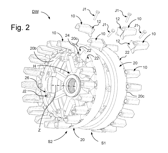
Fig. 2 schematically illustrates a perspective view of a drive wheel DW for an
endless track of a tracked vehicle according to an embodiment of the present
disclosure; and fig. 3 schematically illustrates a side view of the drive
wheel
DW in fig. 2 according to an embodiment of the present disclosure.
The drive wheel DW has a centre axis Z. The drive wheel DW comprises a hub
member H. The hub member H is configured to be operably engaged with the
drive axle of the drive means of the tracked vehicle and configured to be
rotated by the drive means. The hub member H is thus arranged to rotate about
the centre axis Z, see fig. 2 and 3.
io The hub member H has according to this embodiment spokes. The hub
member according to the present disclosure may have any suitable
configuration. The drive means may according to an aspect of the present
disclosure, not shown, be arranged in connection to the drive wheel such that
the drive means, e.g. an electric machine, at least partly is accommodated
within the periphery of the drive wheel, the drive means axle essentially
coaxially coinciding with the centre axis Z of the drive wheel.
The hub member H has a first side H1 and an opposite second side H2. The
hub member H has a front side H1 and an opposite rear side H2, see fig. 3.
The front side H1 is configured to face out from the vehicle and the rear side
zo H2 is configured to face towards the vehicle, when the drive wheel DW is
mounted to the vehicle. The front side H1 is thus facing out from the side of
the vehicle, i.e. in the transversal direction of the vehicle, when the drive
wheel
DW is mounted to the vehicle. The rear side H2 is thus facing towards the
vehicle in the transversal direction of the vehicle, when the drive wheel DW
is
mounted to the vehicle. The front side H1 of the hub member may be denoted
outer side H1 of the hub member H since it faces outwardly from the vehicle
in the lateral direction of the vehicle. The rear side H2 of the hub member
may
be denoted inner side H2 of the hub member H since it faces inwardly in the
lateral direction of the vehicle.
CA 03142705 2021-12-03
WO 2020/246936 PCT/SE2020/050563
According to an embodiment of the present disclosure said drive wheel DW
comprises an outer drive sprocket member Si arranged on the front side H1
of the hub member H and an inner drive sprocket member S2 arranged on the
rear side H2 of the hub member H.
5 The respective drive sprocket member 51, S2 comprises a set of teeth 10
arranged around the circumference of said drive sprocket member 51, S2.
According to this embodiment, the outer drive sprocket member Si comprises
a set of teeth 10 arranged around the circumference of said outer drive
sprocket member Si. According to this embodiment, the inner drive sprocket
10 member S2 comprises a set of teeth 10 arranged around the circumference
of
said inner drive sprocket member S2.
Said teeth are 10 configured to engage with an endless track of the tracked
vehicle.
The respective drive sprocket member Si, S2 comprises a support member
15 20 for teeth of said drive sprocket member Si, S2. According to this
embodiment, the outer drive sprocket member Si comprises a support
member for teeth 10 of said outer drive sprocket member Si. According to this
embodiment, the inner drive sprocket member S2 comprises a support
member for teeth 10 of said inner drive sprocket member S2.
zo Said teeth 10 are configured to be removably attached to said support
member
20.
The support member 20 of the respective drive sprocket member Si, S2 has,
according to the embodiment in fig. 2 and 3, a ring shaped configuration. The
support member 20 of the respective drive sprocket member Si, S2 has an
outer side 20a and an opposite inner side 20b.
The support member 20 of the respective drive sprocket member Si, S2 has
a front side 20c and an opposite rear side 20d.
CA 03142705 2021-12-03
WO 2020/246936 PCT/SE2020/050563
16
The front side 20c of the support member 20 of the outer drive sprocket
member Si is configured to face away from the front side H1 of the hub
member H when attached to the hub member H. The front side 20c of the
support member 20 of the inner drive sprocket member S2 is configured to
face away from the rear side H2 of the hub member H when attached to the
hub member H.
The rear side 20d of the support member 20 of the outer drive sprocket
member Si is configured to face towards the front side H1 of the hub member
H when attached to the hub member H. The rear side 20d of the support
member 20 of the inner drive sprocket member S2 is configured to face
towards the rear side H2 of the hub member H when attached to the hub
member H.
Said teeth 10, when arranged on and distributed around the support member
of the respective drive sprocket member Si, S2, are configured to protrude
15 from said outer side 20a so as to engage with said endless track.
Said teeth 10, when arranged on and distributed around the support member
20 of the respective drive sprocket member Si, S2, are configured to project
from said front side 20c.
The drive wheel according to the present disclosure may according to an
zo aspect of the present disclosure, not shown, be provided with a single
drive
sprocket member. The drive wheel according to the present disclosure may
according to an aspect of the present disclosure be provided with a single
drive
sprocket member, not shown, having teeth arranged around the circumference
of said single drive sprocket member and one support member for said teeth.
The teeth are configured to be removably attached to the single support
member of the drive sprocket member, not shown.
The drive wheel DW comprises a fastening arrangement A for facilitating
fastening one or more teeth 10 of the set of teeth 10 to the support member
20. The drive wheel DW comprises a fastening arrangement A for facilitating
CA 03142705 2021-12-03
WO 2020/246936 PCT/SE2020/050563
17
fastening one or more teeth 10 of the set of teeth 10 to the respective
support
member 20.
Said fastening arrangement A is configured for fastening one or more teeth 10
of the set of teeth 10 to the support member 20. Said fastening arrangement
A comprises a set of dovetail shaped recesses 22 of said support member 20.
Said support member 20 is thus provided with dovetail shaped recesses 22.
According to this embodiment of the present disclosure, the support member
20 of the outer drive sprocket member 51 comprises a set of dovetail shaped
recesses 22 circumferentially arranged around its support member 20.
According to this embodiment of the present disclosure, the support member
of the inner drive sprocket member S2 comprises a set of dovetail shaped
recesses 22 circumferentially arranged around its support member 20.
Each dovetail shaped recess 22 is configured to receive a locking portion 12
of one or more teeth 10 so as to provide a locking function for said one or
more
15 teeth 10.
The set of dovetail shaped recesses 22 are arranged on the front side 20c of
the support member 20 of the respective drive sprocket member 51, S2.
According to an aspect of the present disclosure the fastening arrangement A
further comprises a bolt joint J1 for attaching one or more teeth 10 in
zo association with a dovetail shaped recess 22 of the support member 20 of
the
respective drive sprocket member 51, S2.
According to an aspect of the present disclosure the fastening arrangement A
comprises a set of attachment members 24 arranged around the side of the
respective ring shaped support member 20 in connection to said dovetail
shaped recesses 22, see fig. 2 showing the set of attachment members 24 for
the inner drive sprocket member S2. The each attachment member 24 is
according to this embodiment arranged in connection to a dovetail shaped
recess 22. The respective attachment member 24 is arranged to receive a bolt
joint J1 for attaching the respective tooth 10 to the support member 20.
CA 03142705 2021-12-03
WO 2020/246936 PCT/SE2020/050563
18
According to this embodiment the respective drive sprocket member Si, S2
comprises a set of fastening members 26 arranged around the inner side 20b
of the respective ring shaped support member 20, see fig. 2 showing the set
of fastening members 26 for the inner drive sprocket member S2. The
respective fastening member 26 comprises or is arranged to receive a bolt
joint
J2 for attaching the respective drive sprocket member 51, S2 to the hub
member H of the drive wheel DW. According to this embodiment the fastening
members 26 are attached to spokes of the hub member H.
The outer drive sprocket member Si and hence the fastening arrangement A
is described in more detail below, with reference to fig. 4, 5a and 5b.
Fig. 4 schematically illustrates a front view of a drive sprocket member Si of
a
drive wheel for an endless track of a tracked vehicle according to an
embodiment of the present disclosure; fig. 5a schematically illustrates a side
view of the drive sprocket member Si in fig. 4 according to an embodiment of
the present disclosure; and fig. 5b schematically illustrates a cross
sectional
side view A-A of the drive sprocket member Si in fig. 4 according to an
embodiment of the present disclosure.
The drive wheel comprising such a sprocket member Si may be a drive wheel
according to the drive wheel DW in fig. 1. The drive wheel comprising such a
zo sprocket member Si may be a drive wheel according to the drive wheel DW
in fig. 2 and 3.
Fig. 6a schematically illustrates a perspective view of a portion of the drive
sprocket member Si in fig. 4 according to an embodiment of the present
disclosure; and fig. 6b schematically illustrates a perspective view of a
portion
of the drive sprocket member Si in fig. 4 according to an embodiment of the
present disclosure.
The drive sprocket member Si has a centre axis Z about which the drive
sprocket member is intended to rotate during drive of the vehicle.
CA 03142705 2021-12-03
WO 2020/246936 PCT/SE2020/050563
19
The drive sprocket member Si is according to an aspect of the present
disclosure an outer drive sprocket member Si of a drive wheel, e.g. the drive
wheel DW in fig. 2-3, comprising an inner drive sprocket member arranged on
the inner side of a hub member of the drive wheel and an outer drive sprocket
member arranged on the outer side of the hub member.
The drive sprocket member Si comprises a set of teeth 10 arranged around
the circumference of said drive sprocket member Si.
The drive sprocket member Si comprises a support member 20 for teeth 10
of said drive sprocket member Si.
The support member 20 has according to an aspect of the present disclosure
a ring shaped configuration. The support member 20 has an outer side 20a
providing an outer surface configured to face the endless track of the track
assembly of the vehicle when the drive wheel is mounted to the tracked
vehicle.
The teeth 10, when arranged on and distributed around the support member
20, are configured to project from said outer side 20a. Thus, a portion 11 of
said teeth 10 is configured to project from said outer side 20a so as to
engage
with said endless track.
The teeth 10, when arranged on and distributed around the support member
zo 20, have an outer side 10a providing an outer surface configured to face
the
endless track of the track assembly of the vehicle when the drive wheel is
mounted to the tracked vehicle. The outer side 10a of said teeth 10 correspond
to a surface portion of said portion 11 of said teeth. Said surface portion
and
hence outer side 10a of said teeth is configured to engage with said endless
track.
The teeth 10, when arranged on and distributed around the support member
20, have an inner side 10b configured to face towards the axis Z of the drive
wheel, and hence the drive sprocket member Si.
CA 03142705 2021-12-03
WO 2020/246936 PCT/SE2020/050563
The support member 20 according to an aspect of the present disclosure has
an inner side 20b opposite to said outer side 20a. The support member 20
according to an aspect of the present disclosure has a front side 20c and an
opposite rear side 20d.
5 The dovetail shaped recess 22 is arranged on the front side 20c of said
support
member 20.
The teeth 10 are configured to be removably attached to said support member
20.
The drive sprocket member Si comprises a fastening arrangement A for
io facilitating fastening one or more teeth 10 of the set of teeth 10 to
the support
member 20. The drive sprocket member Si comprises a fastening
arrangement A for facilitating fastening one or more teeth 10 of the set of
teeth
10 to the respective support member 20.
Said fastening arrangement A is configured for fastening one or more teeth 10
15 of the set of teeth 10 to the support member 20. Said fastening
arrangement
A comprises a set of dovetail shaped recesses 22 of said support member 20.
Said support member 20 is thus provided with dovetail shaped recesses 22.
Each dovetail shaped recess 22 is configured to receive a locking portion 12
of one or more teeth 10 so as to provide a locking function for said one or
more
zo teeth 10. According to this embodiment, each dovetail shaped recess 22 is
configured to receive a locking portion 12 of one tooth 10 so as to provide a
locking function for said one or more teeth 10. According to this embodiment,
each tooth 10 comprises a locking portion 12 configured to lockingly fit in
said
dovetail shaped recess 22.
An embodiment of a tooth 10 of the set of teeth 10 of the drive sprocket
member Si is described in more detail with reference to fig. 7a-b and 8a-b.
The locking portion 12 of a tooth 10 of the set of teeth 10 of the drive
sprocket
member Si is described in more detail with reference to fig. 7a-b and 8a-b.
CA 03142705 2021-12-03
WO 2020/246936 PCT/SE2020/050563
21
According to an aspect of the present disclosure the fastening arrangement A
further comprises a bolt joint J1 for attaching one or more teeth 10 in
association with a dovetail shaped recess 22.
The set of dovetail shaped recesses 22 are arranged on the front side 20c of
the support member 20. Each dovetail shaped recess 22 is configured to run
radially in said support member 20. Each dovetail shaped recess 22 is
configured to run radially on the front side 20c of said support member 20.
Said dovetail shaped recess 22 is configured to narrow in the radial direction
from the periphery towards the centre of the support member 20. Said dovetail
shaped recess 22 is configured to narrow in the radial direction from the
periphery of the support member 20 towards the centre, i.e. the central point
of the support member associated with the centre axis of the sprocket member
51, of the support member 20. Said dovetail shaped recess 22 is configured
to narrow in the radial direction from the outer side 20a of the support
member
20 towards the centre of the support member 20.
Said dovetail shaped recess 22 has opposite inner walls 22a, 22b. Said
opposite inner walls 22a, 22b constitutes a first inner wall 22a and an
opposite
second inner wall 22b. The inner walls 22a, 22b are configured to run from the
outer side 20a along the front side 20c towards a central portion of the
support
zo member 20. The inner walls 22a, 22b are configured to run towards each
other
from the outer side towards a central area of the support member 20 and are
thus narrowing each other.
The inner walls 22a, 22b are configured to run from the front side 20c towards
a recess bottom 22c. The recess bottom 22c is thus running from the outer
side 20a along the front side 20c towards a central portion of the support
member 20. The dovetail shaped recess 22 thus has inner walls 22a, 22b and
a recess bottom 22c. The dovetail shaped recess 22 has an inner end 22d at
a certain distance from the inner side 20b of the support member 20, see fig.
CA 03142705 2021-12-03
WO 2020/246936 PCT/SE2020/050563
22
4. The inner end 22d of the respective dovetail shaped recess 22 is according
to this embodiment arranged in connection to the attachment member 24.
As illustrated in fig. 6b, the respective inner wall 22a, 22b of said recess
22
has an inclination a relative to the direction perpendicular to the radial
direction
of the support member 20. The respective inner wall 22a, 22b of said recess
22 has an inclination a relative to the direction parallel to the axial
direction of
the support member 20. The inclination a of the respective inner wall 22a, 22b
is such that the inner walls 22a, 22b are leaning towards each other.
Said dovetail shaped recess 22 is thus configured to narrow outwardly from
io said support member 20. Said dovetail shaped recess 22 is thus
configured to
narrow towards said front side 20c of said support member 20. Said dovetail
shaped recess 22 is thus configured to narrow from said recess bottom 22c
towards said front side 20c of said support member 20.
According to the embodiment illustrated in e.g. fig. 4 and fig. 5a-b each
tooth
10 is configured to be attached to the support member 20 in connection to a
dovetail shaped recess 22. According to the embodiment illustrated in e.g.
fig.
4 and fig. 5a-b each tooth 10 comprises an opening 01, i.e. a through hole,
for
receiving a bolt joint J1. The opening 01 is arranged in connection to the
locking portion 12 of the respective teeth 10.
zo According to an aspect of the present disclosure the fastening
arrangement A
comprises a set of attachment members 24 arranged around the side of the
respective ring shaped support member 20 in connection to said dovetail
shaped recesses 22, see fig. 4. Each attachment member 24 is according to
this embodiment arranged in connection to a dovetail shaped recess 22. The
respective attachment member 24 is arranged to receive a bolt joint J1 for
attaching the respective tooth 10 to the support member 20.
According to this embodiment the drive sprocket member 51 comprises a set
of fastening members 26 arranged around the inner side 20b of the ring
shaped support member 20. The respective fastening member 26 comprises
CA 03142705 2021-12-03
WO 2020/246936 PCT/SE2020/050563
23
or is arranged to receive a bolt joint J2 for attaching the drive sprocket
member
Si to the hub member of the drive wheel, see fig. 4.
Fig. 7a schematically illustrates a plan view of a tooth 10 of the drive
sprocket
member Si in fig. 2 and 4 according to an embodiment of the present
disclosure; fig. 7b schematically illustrates a side view of the tooth 10 in
fig. 7a
according to an embodiment of the present disclosure; fig. 8a schematically
illustrates a rear view of the tooth 10 in fig. 7a according to an embodiment
of
the present disclosure; and fig. 8b schematically illustrates a cross
sectional
side view of the tooth 10 in fig. 8a according to an embodiment of the present
disclosure.
Said tooth 10 has an outer side 10a providing an outer surface configured to
face the endless track of the track assembly of the vehicle when the tooth 10
is attached to the support member and the drive wheel is mounted to the
tracked vehicle, see fig. 7b. Said tooth 10 has an inner side 10b opposite to
said outer side 10a, see fig. 7b.
Said tooth 10 has front side 10c configured to project from the front side of
the
support member when the tooth 10 is attached to the support member, see fig.
7a-b. Said tooth 10 has rear side 10d opposite to said front side 10c, said
rear
side being configured to face the front side of the support member when the
zo tooth 10 is attached to the support member, see fig. 7a-b.
The tooth 10, when arranged on and distributed around the support member
20, is configured to project from the outer side 20a of the support member 20
with a portion 11 of said tooth 10 so as to engage with said endless track,
see
e.g. fig. 4. The outer side 10a of said teeth 10 correspond to a surface
portion
of said portion 11 of said tooth 10.
Said tooth 10 has a first long side 10e configured to run from the front side
10c
towards the rear side 10d, see fig. 7a. Said tooth 10 has a second long side
10f, opposite to said first long side 10e, configured to run from the front
side
10c towards the rear side 10d, see fig. 7a.
CA 03142705 2021-12-03
WO 2020/246936 PCT/SE2020/050563
24
Said tooth 10 has a locking portion 12. The locking portion 12 is shaped to
fit
into a dovetail shaped recess 22 of the support member 20, see e.g. fig. 7a-b.
Said tooth 10 has a wing element 14 arranged in the rear portion of the tooth
10. The locking portion 12 is configured to project rearwardly from the wing
portion 14. The wing element 14 comprises a first wing portion 14a. The first
long side 10e is configured to transcend into said first wing portion 14a. The
wing element 14 comprises a second wing portion 14b opposite to the first
wing portion 14a. The second long side 10f is configured to transcend into
said
second wing portion 14b.
io The locking portion 12 has opposite outer walls 12a, 12b. Said opposite
outer
walls 12a, 12b constitutes a first outer wall 12a and an opposite second outer
wall 12b. The outer walls 12a, 12b are configured to face the inner walls 22a,
22b of the dovetail shaped recess 22 when the tooth 10 is attached to the
support member 20. The outer walls 12a, 12b are configured to run from the
outer side 10a along the front side 20c towards a central portion of the
support
member 20.
The locking portion 12 has an outer side 12c configured to face in the same
direction as the outer side 20a of the support member 20 when the tooth 10 is
attached to the support member 20.
zo The locking portion 12 has an inner side 12d, opposite to said outer
side 12c,
configured to face towards the inner end 22d of the dovetail shaped recess 22
of the support member 20 when the tooth 10 is attached to the support member
20.
The outer walls 12a, 12b are configured to run towards each other from the
outer side towards a central area of the support member 20 and are thus
narrowing each other from the outer side 12c towards the inner side 12d.
CA 03142705 2021-12-03
WO 2020/246936 PCT/SE2020/050563
The rear side 10d of the tooth constitutes the surface side 12e of the locking
portion 12 configured to face the recess bottom 22c of the dovetail shaped
recess 22 of the support member, see e.g. fig. 7a-b and fig. 6a.
According to an aspect of the present disclosure, the locking portion 12 thus
5 has opposite outer walls 12a, 12b configured to face and at least partly
engage
with the opposite inner walls 22a, 22b of the dovetail shaped recess 22, and a
surface side 12e configured to face and at least partly engage with the recess
bottom 22c of the dovetail shaped recess 22, providing efficient geometrical
locking.
10 The foregoing description of the preferred embodiments of the present
invention has been provided for the purposes of illustration and description.
It
is not intended to be exhaustive or to limit the invention to the precise
forms
disclosed. Obviously, many modifications and variations will be apparent to
practitioners skilled in the art. The embodiments were chosen and described
15 in order to best explain the principles of the invention and its
practical
applications, thereby enabling others skilled in the art to understand the
invention for various embodiments and with the various modifications suited to
the particular use contemplated.