Note: Descriptions are shown in the official language in which they were submitted.
CA 03143026 2021-12-08
WO 2020/252276
PCT/US2020/037455
1
SYSTEM FOR NON-INVASIVE MEASUREMENT OF AN ANALYTE IN A
VEHICLE DRIVER
APPLICANT
Automotive Coalition for Traffic Safety, Inc.
INVENTORS
Johannes Koeth
Nicolas Koslowski
REFERENCE TO PENDING PRIOR PATENT APPLICATION
This patent application claims benefit of pending prior U.S. Provisional
Patent Application Serial No. 62/860,413, filed 06/12/2019 by Automotive
Coalition for Traffic Safety, Inc. and Johannes Koeth et al. for SYSTEM FOR
NON-INVASIVE MEASUREMENT OF AN ANALYTE IN A VEHICLE
DRIVER (Attorney's Docket No. ACTS-4 PROV), which patent application is
hereby incorporated herein by reference.
BACKGROUND
2 0 The present application generally relates to a system and methods
for non-
invasively measuring an analyte in a vehicle driver. More specifically, the
application relates to a measurement quantitative spectroscopy system for
measuring the presence or concentration of an analyte, for example, alcohol,
alcohol byproducts, alcohol adducts, or substances of abuse, utilizing non-
invasive techniques in combination with multivariate analysis.
Current practice for alcohol measurements is based upon either blood
measurements or breath testing.
CA 03143026 2021-12-08
WO 2020/252276
PCT/US2020/037455
- 2 -
Blood measurements define the gold standard for determining alcohol
intoxication levels. However, blood measurements require either a venous or
capillary sample and involve significant handling precautions in order to
minimize health risks. Once extracted, the blood sample must be properly
labeled
and transported to a clinical laboratory or other suitable location where a
clinical
gas chromatograph is typically used to measure the blood alcohol level. Due to
the invasiveness of the procedure and the amount of sample handling involved,
blood alcohol measurements are usually limited to critical situations such as
for
traffic accidents, violations where the suspect requests this type of test,
and
1 0 accidents where injuries are involved.
Because it is less invasive, breath testing is more commonly encountered
in the field. In breath testing, the subject must expire air into the
instrument for a
sufficient time and volume to achieve a stable breath flow that originates
from the
alveoli deep within the lungs. The device then measures the alcohol content in
the air, which is related to blood alcohol through a breath-blood partition
coefficient. The blood-breath partition coefficient used in the United States
is
2100 (implied units of mg Et0H/dL blood per mg Et0H/dL air) and varies
between 1900 and 2400 in other nations. The variability in the partition
coefficient is due to the fact that it is highly subject dependent. In other
words,
each subject will have a partition coefficient in the 1900 to 2400 range that
depends on his or her physiology. Since knowledge of each subject's partition
coefficient is unavailable in field applications, each nation assumes a single
partition coefficient value that is globally applied to all measurements. In
the
U.S., defendants in DUI cases often use the globally applied partition
coefficient
as an argument to impede prosecution.
Breath measurements have additional limitations. First, the presence of
"mouth alcohol" can falsely elevate the breath alcohol measurement. This
necessitates a 15-minute waiting period prior to making a measurement in order
to
CA 03143026 2021-12-08
WO 2020/252276
PCT/US2020/037455
- 3 -
ensure that no mouth alcohol is present. For a similar reason, a 15 minute
delay is
required for individuals who are observed to burp or vomit. A delay of 10
minutes or more is often required between breath measurements to allow the
instrument to return to equilibrium with the ambient air and zero alcohol
levels.
In addition, the accuracy of breath alcohol measurements is sensitive to
numerous
physiological and environmental factors.
Multiple government agencies, and society in general, seek non-invasive
alternatives to blood and breath alcohol measurements.
Quantitative spectroscopy offers the potential for a completely non-
invasive alcohol measurement that is not sensitive to the limitations of the
current
measurement methodologies. While non-invasive determination of biological
attributes by quantitative spectroscopy has been found to be highly desirable,
it
has been very difficult to accomplish. Attributes of interest include, as
examples,
analyte presence, analyte concentration (e.g., alcohol concentration),
direction of
change of an analyte concentration, rate of change of an analyte
concentration,
disease presence (e.g., alcoholism), disease state, and combinations and
subsets
thereof Non-invasive measurements via quantitative spectroscopy are desirable
because they are painless, do not require a fluid draw from the body, carry
little
risk of contamination or infection, do not generate any hazardous waste, and
can
2 0 have short measurement times.
Several systems have been proposed for the non-invasive determination of
attributes of biological tissue. These systems have included technologies
incorporating polarimetry, mid-infrared spectroscopy, Raman spectroscopy,
Kromoscopy, fluorescence spectroscopy, nuclear magnetic resonance
spectroscopy, radio-frequency spectroscopy, ultrasound, transdermal
measurements, photo-acoustic spectroscopy, and near-infrared spectroscopy.
However, these systems have not replaced direct and invasive measurements.
As an example, Robinson et al. in U.S. Pat. No. 4,975,581 disclose a
CA 03143026 2021-12-08
WO 2020/252276
PCT/US2020/037455
- 4 -
method and apparatus for measuring a characteristic of unknown value in a
biological sample using infrared spectroscopy in conjunction with a
multivariate
model that is empirically derived from a set of spectra of biological samples
of
known characteristic values. The above-mentioned characteristic is generally
the
concentration of an analyte, such as alcohol, but also can be any chemical or
physical property of the sample. The method of Robinson et al. involves a two-
step process that includes both calibration and prediction steps.
In the calibration step, the infrared light is coupled to calibration samples
of known characteristic values so that there is attenuation with known
1 0 characteristic values of at least several wavelengths of the infrared
radiation as a
function of the various components and analytes comprising the sample. The
infrared light is coupled to the sample by passing the light through the
sample or
by reflecting the light off the sample. Absorption of the infrared light by
the
sample causes intensity variations of the light that are a function of the
wavelength of the light. The resulting intensity variations at a minimum of
several wavelengths are measured for the set of calibration samples of known
characteristic values. Original or transformed intensity variations are then
empirically related to the known characteristics of the calibration samples
using
multivariate algorithms to obtain a multivariate calibration model. The model
preferably accounts for subject variability, instrument variability, and
environment variability.
In the prediction step, the infrared light is coupled to a sample of unknown
characteristic value, and a multivariate calibration model is applied to the
original
or transformed intensity variations of the appropriate wavelengths of light
measured from this unknown sample. The result of the prediction step is the
estimated value of the characteristic of the unknown sample. The disclosure of
Robinson et al. is incorporated herein by reference.
A further method of building a calibration model and using such model for
CA 03143026 2021-12-08
WO 2020/252276
PCT/US2020/037455
- 5 -
prediction of analytes and/or attributes of tissue is disclosed in U.S. Pat.
No.
6,157,041 to Thomas et al., entitled "Method and Apparatus for Tailoring
Spectrographic Calibration Models," the disclosure of which is incorporated
herein by reference.
In U.S. Pat. No. 5,830,112, Robinson describes a general method of robust
sampling of tissue for non-invasive analyte measurement. The sampling method
utilizes a tissue-sampling accessory that is pathlength-optimized by spectral
region for measuring an analyte such as alcohol. The patent discloses several
types of spectrometers for measuring the spectrum of the tissue from 400 to
2500
1 0 nm, including acousto-optical tunable filters, discrete wavelength
spectrometers,
filters, grating spectrometers and FTIR spectrometers. The disclosure of
Robinson is incorporated herein by reference.
Although there has been substantial work conducted in attempting to
produce commercially viable non-invasive near-infrared spectroscopy-based
systems for determination of biological attributes, no such device is
presently
available. It is believed that prior art systems discussed above have failed
for one
or more reasons to fully meet the challenges imposed by the spectral
characteristics of tissue which make the design of a non-invasive measurement
system a formidable task. Thus, there is a substantial need for a commercially
2 0 viable system which incorporates subsystems and methods with sufficient
accuracy and precision to make clinically relevant determinations of
biological
attributes in human tissue.
SUMMARY
One embodiment of the invention relates to a system for non-invasively
measuring an analyte in a vehicle driver and controlling a vehicle based on a
measurement of the analyte. The system includes at least one solid-state light
source, a sample device, one or more optical detectors (sometimes also
referred to
CA 03143026 2021-12-08
WO 2020/252276
PCT/US2020/037455
- 6 -
herein as a photodetector) and a controller. The at least one solid-state
light
source is configured to emit different wavelengths of light. The sample device
is
configured to introduce the light emitted by the at least one solid-state
light source
into tissue of the vehicle driver. The one or more optical detectors are
configured
to detect a portion of the light that is not absorbed by the tissue of the
vehicle
driver. The controller is configured to calculate a measurement of the analyte
in
the tissue of the vehicle driver based on the light detected by the one or
more
optical detectors, determine whether the measurement of the analyte in the
tissue
of the vehicle driver exceeds a pre-determined value, and provide a signal to
a
1 0 device configured to control the vehicle.
In one construction, a novel tissue interface device is provided wherein the
novel tissue interface device combines the functionalities of sampling and
data
acquisition in a single unit which is disposed adjacent to the tissue surface.
Another embodiment of the invention relates to a method for non-
invasively measuring an analyte in a vehicle driver and controlling a vehicle
based on a measurement of the analyte. A sample device introduces different
wavelengths of light emitted by at least one solid-state light source into
tissue of
the vehicle driver. One or more optical detectors detect a portion of the
light that
is not absorbed by the tissue of the vehicle driver. A controller calculates a
measurement of the analyte in the tissue of the vehicle driver based on the
light
detected by the one or more optical detectors. The controller determines
whether
the measurement of the analyte in the tissue of the vehicle driver exceeds a
pre-
determined value and controls the vehicle based on the measurement of the
analyte in the tissue of the vehicle driver.
In one method, a novel tissue interface device is used which combines the
functionalities of sampling and data acquisition in a single unit which is
disposed
adjacent to the tissue surface.
CA 03143026 2021-12-08
WO 2020/252276
PCT/US2020/037455
- 7 -
Additional features, advantages, and embodiments of the present
disclosure may be set forth from consideration of the following detailed
description, drawings, and claims. Moreover, it is to be understood that both
the
foregoing summary of the present disclosure and the following detailed
description are exemplary and intended to provide further explanation without
further limiting the scope of the present disclosure claimed.
In one preferred form of the present invention, there is provided a sample
interface device for use in identifying the presence of an analyte in a
sample,
wherein the sample interface device delivers a plurality of monochromatic
light
beams to a sample and receives back scattered light from the sample, the
sample
interface device comprising:
a substrate;
a low-absorbance injection area carried by the substrate for receiving a
plurality of monochromatic light beams and delivering the plurality of
monochromatic light beams to the sample; and
a plurality of concentrically-located, ring-shaped photosensors carried by
the substrate, wherein the plurality of concentrically-located, ring-shaped
photosensors are disposed progressively radially outboard of the low-
absorbance
injection area, and further wherein each of the concentrically-located, ring-
shaped
photosensors produces an electrical signal which corresponds to the amount of
light received by that concentrically-located, ring-shaped photosensor.
In another preferred form of the present invention, there is provided a
method for delivering a plurality of monochromatic light beams to a sample and
detecting scattered light returning from the sample, the method comprising:
providing a sample interface device, the sample interface device
comprising:
a substrate;
CA 03143026 2021-12-08
WO 2020/252276
PCT/US2020/037455
- 8 -
a low-absorbance injection area carried by the substrate for
receiving a plurality of monochromatic light beams and delivering the
plurality of
monochromatic light beams to the sample; and
a plurality of concentrically-located, ring-shaped photosensors
carried by the substrate, wherein the plurality of concentrically-located,
ring-
shaped photosensors are disposed progressively radially outboard of the low-
absorbance injection area, and further wherein each of the concentrically-
located,
ring-shaped photosensors produces an electrical signal which corresponds to
the
amount of light received by that concentrically-located, ring-shaped
photosensor;
introducing a plurality of monochromatic light beams into the low-
absorbance injection area of the sample interface device so that the plurality
of
monochromatic light beams are delivered to the sample; and
using the plurality of concentrically-located, ring-shaped photosensors on
the sample interface device to detect scattered light returning from the
sample.
In another preferred form of the present invention, there is provided a
system for the non-invasive measurement of an analyte in a sample, wherein the
system comprises:
an illumination unit for generating a plurality of monochromatic light
beams, wherein the plurality of monochromatic light beams constitute a
plurality
of different wavelengths; and
a sampling unit for receiving the plurality of monochromatic light beams
from the illumination unit, delivering those monochromatic light beams to the
sample, receiving scattered light back from the sample, and converting the
scattered light into corresponding electrical signals for subsequent
processing and
analyte assessment, wherein the sampling unit comprises:
a sample interface device, the sample interface device comprising:
a substrate;
CA 03143026 2021-12-08
WO 2020/252276
PCT/US2020/037455
- 9 -
a low-absorbance injection area carried by the substrate for
receiving the plurality of monochromatic light beams and delivering the
plurality
of monochromatic light beams to the sample; and
a plurality of concentrically-located, ring-shaped
photosensors carried by the substrate, wherein the plurality of concentrically-
located, ring-shaped photosensors are disposed progressively radially outboard
of
the low-absorbance injection area, and further wherein each of the
concentrically-
located, ring-shaped photosensors produces an electrical signal which
corresponds
to the amount of light received by that concentrically-located, ring-shaped
photosensor.
In another preferred form of the present invention, there is provided a
method for detecting an analyte in a sample, the method comprising:
providing a system, wherein the system comprises:
an illumination unit for generating a plurality of monochromatic
light beams, wherein the plurality of monochromatic light beams constitute a
plurality of different wavelengths; and
a sampling unit for receiving the plurality of monochromatic light
beams from the illumination unit, delivering those monochromatic light beams
to
the sample, receiving scattered light back from the sample, and converting the
2 0 scattered light into corresponding electrical signals for subsequent
processing and
analyte assessment, wherein the sampling unit comprises:
a sample interface device, the sample interface device
comprising:
a substrate;
a low-absorbance injection area carried by the
substrate for receiving the plurality of monochromatic light beams and
delivering
the plurality of monochromatic light beams to the sample; and
CA 03143026 2021-12-08
WO 2020/252276
PCT/US2020/037455
- 10 -
a plurality of concentrically-located, ring-shaped
photosensors carried by the substrate, wherein the plurality of concentrically-
located, ring-shaped photosensors are disposed progressively radially outboard
of
the low-absorbance injection area, and further wherein each of the
concentrically-
located, ring-shaped photosensors produces an electrical signal which
corresponds
to the amount of light received by that concentrically-located, ring-shaped
photosensor;
introducing a plurality of monochromatic light beams into the low-
absorbance injection area of the sample interface device so that the plurality
of
1 0 monochromatic light beams are delivered to the sample; and
using the plurality of concentrically-located, ring-shaped photosensors on
the sample interface device to detect scattered light returning from the
sample.
BRIEF DESCRIPTION OF THE DRAWINGS
The accompanying drawings, which are incorporated in and constitute a
part of this specification, illustrate preferred embodiments of the invention
and
together with the description serve to explain principles of the invention. No
attempt is made to show structural details of the present disclosure in more
detail
than may be necessary for a fundamental understanding of the present
disclosure
and the various ways in which it may be practiced.
FIG. 1 is a schematic depiction of a non-invasive spectroscopy system
incorporating the disclosed subsystems.
FIG. 2 is a graphical depiction of the concept of net attribute signal in a
three-component system.
FIG. 3 is an embodiment of an electronic circuit designed to control the
drive current of a solid-state light source including means for turning the
light
source on and off
FIG. 4 is an embodiment of an electronic circuit designed to control the
CA 03143026 2021-12-08
WO 2020/252276
PC T/US2020/037455
- 11 -
drive current of a solid-state light source including means for turning the
light
source on and off and altering the desired drive current.
FIG. 5 is an embodiment of the illumination/modulation subsystem of
FIG. 1 comprising multiple individual solid-state light sources arranged in an
array whose outputs are introduced to a hexagonal cross-section internally-
reflective light homogenizer.
FIG. 6 is an embodiment of a single laser emitter in a semiconductor chip.
FIG. 7 is an embodiment of the illumination/modulation subsystem where
multiple laser emitters are mounted to a common carrier.
FIG. 8 is an embodiment of the illumination/modulation subsystem that
depicts a laser bar comprised of a single semiconductor chip that contains 24
emitters (12 different wavelengths, 2 emitters per wavelength).
FIG. 9 is a schematic view of an embodiment of a fiber optic coupler that
collects light emitted from each pair of emitters in the laser bar embodiment
shown in FIG. 8 and combines the individual optical fibers into an output
bundle
or cable.
FIG. 10 is an embodiment that combines the outputs of 4 different fiber
couplers into a single output aperture/bundle, where each couple is connected
to a
different laser bar.
2 0 FIG. 11 is an exemplary embodiment of a light homogenizer suitable
for
homogenizing the light from the illumination/modulation subsystem's output
aperture/bundle.
FIG. 12 is a perspective view of elements of a tissue sampling subsystem
of FIG. 1.
FIG. 13 is a view of an ergonomic apparatus of the tissue sampling
subsystem which holds the sample (e.g., the finger of a user).
FIG. 14 is an embodiment of the sampling surface of the tissue sampling
subsystem, showing an arrangement of illumination and collection optical
fibers.
CA 03143026 2021-12-08
WO 2020/252276
PCT/US2020/037455
- 12 -
FIG. 15 is an alternative embodiment of the sampling surface of the tissue
sampling subsystem.
FIG. 16 is an alternative embodiment of the sampling surface of the tissue
sampling subsystem that is optimized for the small emission area of some solid-
state light source-based illumination/modulation subsystems.
FIG. 17 is a diagram view of the interface between the sampling surface
and the tissue when topical interferents are present on the tissue.
FIG. 18 is a schematic representation of the data acquisition subsystem of
FIG. 1.
FIG. 19 is a diagram of the hybrid calibration formation process.
FIG. 20 demonstrates the effectiveness of multivariate calibration outlier
metrics for detecting the presence of topical interferents.
FIG. 21 shows normalized near-infrared (NIR) spectra of 1300 and 3000
K blackbody radiators over the 100-33000 cm' (100-0.3 p.m) range.
FIG. 22 shows a schematic view of the components of an exemplary
embodiment of the present invention.
FIG. 23 depicts non-invasive tissue spectra acquired using 22
wavelengths.
FIG. 24 compares non-invasive tissue alcohol concentrations obtained
2 0 from the spectra in FIG. 23 to contemporaneous capillary blood alcohol
concentration.
FIG. 25 depicts non-invasive tissue spectra acquired using 39
wavelengths.
FIG. 26 compares non-invasive tissue alcohol concentrations obtained
from the spectra in FIG. 25 to contemporaneous capillary blood alcohol
concentration.
FIG. 27 depicts one of the many possible embodiments of a measurement
timeline including system calibration, measurement, and counter-measure time
CA 03143026 2021-12-08
WO 2020/252276
PCT/US2020/037455
- 13 -
zones.
FIG. 28 depicts a non-invasive monitoring system incorporated in a
vehicle starter button in a vehicle instrument panel.
FIG. 29a depicts a side view of a non-invasive measurement portal
interface where the emitter is a wavelength homogenizer directly connected to
wavelength light sources.
FIG. 29b depicts a top view of the non-invasive measurement portal
interface of FIG. 29a where the emitter is a wavelength homogenizer directly
connected to wavelength light sources.
FIG. 30 depicts the components of a non-invasive monitoring system
which utilizes a broadly tunable laser emitter to provide a means for
spectrally
separated absorption measurements.
FIG. 31 depicts one of the many possible embodiments of a measurement
timeline to improve the average required measurement time where the initial
measurement detects the existence of an analyte, and a subsequent measurement
is made to determine the actual concentration of the analyte.
FIG. 32 depicts a non-invasive monitoring system where the primary
analyte measurement is made through a touch system and a secondary
measurement is made through an alternative analyte detection system.
FIG. 33 depicts the components of a non-invasive monitoring system
which utilizes a blackbody light source with filter elements to provide the
selection of discrete wavelengths to compose the emitted light source.
FIG. 34 depicts the intensity of a light source during transition from an off
state to an on state, where the measurement is made prior to the intensity
settling.
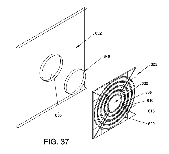
FIGS. 35-40 depict a novel tissue interface device wherein the novel tissue
interface device combines the functionalities of sampling and data acquisition
in a
single unit which is disposed adjacent to the tissue surface.
CA 03143026 2021-12-08
WO 2020/252276
PCT/US2020/037455
- 14 -
DETAILED DESCRIPTION
Before turning to the figures, which illustrate the exemplary embodiments
in detail, it should be understood that the present disclosure is not limited
to the
details or methodology set forth in the description or illustrated in the
figures. It
should also be understood that the terminology is for the purpose of
description
only and should not be regarded as limiting. An effort has been made to use
the
same or like reference numbers throughout the drawings to refer to the same or
like parts.
1 0 Definitions
For the purposes of the present application, the term "analyte
concentration" generally refers to the concentration of an analyte, such as
alcohol.
The term "analyte property" includes analyte concentration and other
properties,
such as the presence or absence of the analyte or the direction or rate of
change of
the analyte concentration, or a biometric, which can be measured in
conjunction
with, or instead of, the analyte concentration. While the disclosure generally
discusses alcohol as the "analyte" of interest, other analytes, including but
not
limited to substances of abuse, alcohol biomarkers, and alcohol byproducts,
are
also intended to be covered by the systems and methods disclosed in the
present
application. The term "alcohol" is used as an example analyte of interest; the
term
is intended to include ethanol, methanol, ethyl glycol or any other chemical
commonly referred to as alcohol. For the purposes of this application, the
term
"alcohol byproducts" includes the adducts and byproducts of the metabolism of
alcohol by the body including, but not limited to, acetone, acetaldehyde, and
acetic acid. The term "alcohol biomarkers" includes, but is not limited to,
Gamma
Glutamyl Transferase (GGT), Aspartate Amino Transferase (AST), Alanine
Amino Transferase (ALT), Mean Corpuscular Volume (MCV), Carbohydrate-
Deficient Transferrin (CDT), Ethyl Glucuronide (EtG), Ethyl Sulfate (EtS), and
CA 03143026 2021-12-08
WO 2020/252276
PCT/US2020/037455
- 15 -
Phosphatidyl Ethanol (PEth). The term "substances of abuse" includes, but is
not
limited to, THC (Tetrahydrocannabinol or marijuana), cocaine, M-AMP
(methamphetamine), OPT (morphine and heroin), OxyContin, Oxycodone, and
PCP (phencyclidine). The term "biometric" refers to an analyte or biological
characteristic that can be used to identify or verify the identity of a
specific person
or subject. The present application discloses systems and methods that address
the need for analyte measurements of samples utilizing spectroscopy where the
term "sample" generally refers to biological tissue. The term "subject"
generally
refers to a person from whom a sample measurement was acquired.
The terms "solid-state light source" and/or "semiconductor light source"
refer to all sources of light, whether spectrally narrow (e.g., a laser) or
broad (e.g.,
an LED) that are based upon semiconductors which include, but are not limited
to, light emitting diodes (LED's), vertical cavity surface emitting lasers
(VCSEL's), horizontal cavity surface emitting lasers (HCSEL's), quantum
cascade
lasers, quantum dot lasers, diode lasers, or other semiconductor diodes or
lasers.
The term "diode laser" refers to any laser where the active medium is based on
a
semiconductor and includes, but is not limited to, double heterostructure
lasers,
quantum well lasers, quantum cascade lasers, separate confinement
heterostructure lasers, distributed feedback (DFB) lasers, VCSEL's, VECSEL's,
2 0 HCSEL's, external-cavity diode lasers, and Fabry-Perot lasers.
Furthermore,
plasma light sources and organic LED's, while not strictly based on
semiconductors, are also contemplated in the embodiments of the present
invention and are thus included under the "solid-state light source" and/or
"semiconductor light source" definitions for the purposes of this application.
For the purposes of this application the term "dispersive spectrometer"
indicates a spectrometer based upon any device, component, or group of
components that spatially separate one or more wavelengths of light from other
wavelengths. Examples include, but are not limited to, spectrometers that use
one
CA 03143026 2021-12-08
WO 2020/252276
PCT/US2020/037455
- 16 -
or more diffraction gratings, prisms, and/or holographic gratings. For the
purposes of this application the term "interferometric/modulating
spectrometer"
indicates a class of spectrometers based upon the optical modulation of
different
wavelengths of light to different frequencies in time or selectively transmits
or
reflects certain wavelengths of light based upon the properties of light
interference. Examples include, but are not limited to, Fourier transform
interferometers, Sagnac interferometers, mock interferometers, Michelson
interferometers, one or more etalons, and/or acousto-optical tunable filters
(AOTF's). One skilled in the art will recognize that spectrometers based on
1 0 combinations of dispersive and interferometric/modulating properties,
such as
those based on lamellar gratings, are also contemplated as being used with the
systems and methods disclosed in the present application.
The present application discloses the use of "signals" in some of the
examples as absorbance or other spectroscopic measurements. Signals can
comprise any measurement obtained concerning the spectroscopic measurement
of a sample or change in a sample, e.g., absorbance, reflectance, intensity of
light
returned, fluorescence, transmission, Raman spectra, or various combinations
of
measurements, at one or more wavelengths. Some embodiments make use of one
or more "models", where such a model can be anything that relates a signal to
the
desired property. Some examples of models include those derived from
multivariate analysis methods, such as partial least squares regression (PLS),
linear regression, multiple linear regression (MLR), classical least squares
regression (CLS), neural networks, discriminant analysis, principal components
analysis (PCA), principal components regression (PCR), discriminant analysis,
neural networks, cluster analysis, and K-nearest neighbors. Single or multi-
wavelength models based on the Beer-Lambert law are special cases of classical
least squares and are thus included in the term multivariate analysis for the
purposes of the present application.
CA 03143026 2021-12-08
WO 2020/252276
PCT/US2020/037455
- 17 -
For the purposes of the present application, the term "about" applies to all
numeric values, whether or not explicitly indicated. The term "about"
generally
refers to a range of numbers that one of skill in the art would consider
equivalent
to the recited value (i.e., having the same function or result). In some
instances,
the term "about" can include numbers that are rounded to the nearest
significant
figure.
The Novel System And Methods In General
Spectroscopic measurement systems typically require some means for
1 0 resolving and measuring different wavelengths of light in order to
obtain a
spectrum. Some common approaches to achieve the desired spectrum include
dispersive (e.g. grating and prism based) spectrometers and interferometric
(e.g.
Michelson, Sagnac, or other interferometer) spectrometers. Non-invasive
measurement systems that incorporate such approaches are often limited by the
expensive nature of dispersive and interferometric devices, as well as their
inherent size, fragility, and sensitivity to environmental effects. The
present
application discloses systems and methods that can provide an alternative
approach for generating, resolving and recording the intensities of different
wavelengths of light interacting with a sample, using solid-state light
sources such
2 0 as light emitting diodes (LED's), vertical cavity surface emitting
lasers
(VCSEL's), horizontal cavity surface emitting lasers (HCSEL's), diode lasers,
quantum cascade lasers, or other solid-state light sources, and using optical
detectors such as photodiodes.
Referring generally to the figures, the disclosed system overcomes the
challenges posed by the spectral characteristics of tissue by incorporating a
design
that includes, in some embodiments, optimized subsystems. The design contends
with the complexities of the tissue spectrum, high signal-to-noise ratio (SNR)
and
photometric accuracy requirements, tissue sampling errors, calibration
CA 03143026 2021-12-08
WO 2020/252276
PCT/US2020/037455
- 18 -
maintenance problems, calibration transfer problems plus a host of other
issues.
The subsystems can include an illumination/modulation subsystem, a tissue
sampling subsystem, a data acquisition subsystem, a computing subsystem, and a
calibration subsystem.
An apparatus and method for non-invasive determination of attributes of
human tissue by quantitative near-infrared spectroscopy is disclosed herein.
The
system includes subsystems optimized to contend with the complexities of the
tissue spectrum, high signal-to-noise ratio and photometric accuracy
requirements, tissue sampling errors, calibration maintenance problems, and
1 0 calibration transfer problems. The subsystems include an
illumination/modulation subsystem, a tissue sampling subsystem, a data
acquisition subsystem, and a computing subsystem.
The present application further discloses apparatus and methods that allow
for implementation and integration of each of these subsystems in order to
maximize the net attribute signal-to-noise ratio. The net attribute signal is
the
portion of the near-infrared spectrum that is specific for the attribute of
interest
because it is orthogonal to all other sources of spectral variance. The
orthogonal
nature of the net attribute signal makes it perpendicular to the space defined
by
any interfering species and, as a result, the net attribute signal is
uncorrelated to
these sources of variance. The net attribute signal-to-noise ratio is directly
related
to the accuracy and precision for non-invasive determination of the attribute
by
quantitative near-infrared spectroscopy.
The present application discloses the use of near-infrared radiation for
analysis. Radiation in the wavelength range of 1.0 to 2.5 microns (or
wavenumber range of 10,000 to 4,000 cm') can be suitable for making some non-
invasive measurements because such radiation has acceptable specificity for a
number of analytes, including alcohol, along with tissue optical penetration
depths
of up to several millimeters with acceptable absorbance characteristics. In
the 1.0
CA 03143026 2021-12-08
WO 2020/252276
PCT/US2020/037455
- 19 -
to 2.5 micron spectral region, the large number of optically active substances
that
make up the tissue complicate the measurement of any given substance due to
the
overlapping nature of their absorbance spectra. Multivariate analysis
techniques
can be used to resolve these overlapping spectra such that accurate
measurements
of the substance of interest can be achieved. Multivariate analysis
techniques,
however, can require that multivariate calibrations remain robust over time
("calibration maintenance") and be applicable to multiple instruments
("calibration transfer"). Other wavelength regions, such as the visible and
infrared, can also be suitable for the disclosed systems and methods.
1 0 The present application discloses a multidisciplinary approach to
the
design of a spectroscopic instrument that incorporates an understanding of the
instrument subsystems, tissue physiology, multivariate analysis, near-infrared
spectroscopy and overall system operation. Further, the interactions between
the
subsystems have been analyzed so that the behavior and requirements for the
entire non-invasive measurement device are well understood and result in a
design for a commercial instrument that will make non-invasive measurements
with sufficient accuracy and precision at a price and size that is
commercially
viable.
The present application also discloses systems and methods for use with
the unique sensing requirements for transportation systems including, but not
limited to, motorcycles, automobiles, trucks, ships, trains and aircraft;
where the
system must operate over a wide range of temperature, atmospheric pressure,
altitudes, humidity, mechanical orientation, ambient lighting and
environmental
constituent (e.g., salt, sand, dust, smoke) environments. The disclosed system
may operate over a full range of potential users distinguishable through
differences in weight, stature, age, ethnicity, gender, health, fitness level
and other
human distinguishing factors. The disclosed system may remain functional over
a
full vehicle life and maintain diagnostics and telltales indicating required
CA 03143026 2021-12-08
WO 2020/252276
PCT/US2020/037455
- 20 -
maintenance or serviceable unit replacement. The disclosed system can provide
a
human machine interface which provides visual, haptic, and/or audible feedback
to inform the system user of a correct and incorrect measurement. The system
can provide diagnostics and user feedback indicating proper and improper
measurements including detection of intentional and un-intentional system
tampering or measurement spoofing. The system can maintain operational modes
which can be enabled/disabled based on administrative controls (e.g.,
passwords).
The system can provide one or more communication and/or power interfaces to
external transportation-enabling or human machine interface systems using one
or
more existing or developed communication protocols to receive data and/or
power
required for system operation or to enable, disable or modify the operation of
the
external systems. The system can support the capability to allow for
measurement accuracy and precision verification or calibration during
manufacturing, installation and/or service through a prosthetic reference
device.
The subsystems of the novel non-invasive system are highly optimized to
provide reproducible and, preferably, uniform radiance of the tissue, low
tissue
sampling error, depth targeting of the tissue layers that contain the property
of
interest, efficient collection of diffuse reflectance spectra from the tissue,
high
optical throughput, high photometric accuracy, large dynamic range, excellent
2 0 thermal stability, effective calibration maintenance, effective
calibration transfer,
built-in quality control, and ease-of-use.
Referring now to FIG. 1, there is shown, in schematic view, a novel non-
invasive system 5 that is able to achieve acceptable levels of accuracy and
precision for analyte property measurements. The overall system 5 can be
viewed, for discussion purposes, as comprising five subsystems; those skilled
in
the art will appreciate other subdivisions of the functionality disclosed. The
subsystems include an illumination/modulation subsystem 100, a tissue sampling
subsystem 200, a data acquisition subsystem 300, a computing subsystem 400,
CA 03143026 2021-12-08
WO 2020/252276
PCT/US2020/037455
-21 -
and a calibration subsystem 500. It will be appreciated that the novel non-
invasive system 5 may be embodied in, or considered to be, an instrument, and
so
hereinafter, the term instrument may be considered to refer to the novel non-
invasive system 5 where the context so admits. It will also be appreciated
that the
novel non-invasive system 5 may be embodied in, or considered to be, a device,
and so hereinafter, the term device may be considered to refer to the novel
non-
invasive system 5 where the context so admits (however, it should be
appreciated
that the term device may also refer to a subsystem or element of non-invasive
system 5 where the context so submits).
1 0 The subsystems can be designed and integrated in order to achieve
a
desirable net attribute signal-to-noise ratio. The net attribute signal is the
portion
of the near-infrared spectrum that is specific for the attribute of interest
because it
is orthogonal to other sources of spectral variance. FIG. 2 is a graphical
representation of the net attribute signal in a three-dimensional system. The
net
attribute signal-to-noise ratio is directly related to the accuracy and
precision of
the non-invasive attribute determination by quantitative near-infrared
spectroscopy.
The subsystems provide reproducible and preferably spatially-uniform
radiance of the tissue, low tissue sampling error, depth targeting of
appropriate
layers of the tissue, efficient collection of diffuse reflectance spectra from
the
tissue, high optical throughput, high photometric accuracy, large dynamic
range,
excellent thermal stability, effective calibration maintenance, effective
calibration
transfer, built-in quality control and ease-of-use. Each of the subsystems is
discussed below in more detail.
Illumination/Modulation Subsystem 100
The illumination/modulation subsystem 100 generates the light used to
interrogate the sample (e.g., the skin tissue of a human).
CA 03143026 2021-12-08
WO 2020/252276
PCT/US2020/037455
- 22 -
In classical spectroscopy using dispersive or interferometric
spectrometers, the spectrum of a polychromatic light source (or light emitted
from
a sample of interest) is measured either by dispersing the different
wavelengths of
light spatially (e.g., using a prism or a diffraction grating) or by
modulating
different wavelengths of light to different frequencies (e.g., using a
Michelson
interferometer). In these cases, a spectrometer (a subsystem distinct from the
light source) is required to perform the function of "encoding" different
wavelengths either spatially or in time such that each can be measured
substantially independently of other wavelengths. While dispersive and
1 0 interferometric spectrometers are known in the art and can adequately
serve their
function in some environments and applications, they can be limited by their
cost,
size, fragility, signal-to-noise ratio (SNR), and complexity in other
applications
and environments.
An advantage of the solid-state light sources incorporated in the disclosed
systems is that the sources can be independently modulated in intensity. Thus,
multiple solid-state light sources that emit different wavelengths of light
can be
used, with each solid-state light source modulated at a different frequency or
collectively modulated according to a predefined scheme such as those defined
by
a Hadamard or similar approach. The independently modulated solid-state light
2 0 sources can be optically combined into a single beam and introduced to
the
sample. A portion of the light can be collected from the sample and measured
by
a single photodetector (sometimes also referred to herein as an optical
detector).
The result is the provision of a solid-state light source in an
illumination/modulation subsystem that can offer significant benefits in size,
cost,
energy consumption, and overall system stability since the spectrometer is
eliminated from the measurement system. Furthermore, as all wavelengths are
independently modulated and can be combined into a single beam, a single
element photodetector (rather than an array of photodetectors) is suitable to
detect
CA 03143026 2021-12-08
WO 2020/252276
PCT/US2020/037455
- 23 -
all analytical light. This can represent a significant reduction in system
complexity and cost relative to systems and embodiments with multiple
photodetector elements.
Several parameters of systems for measuring analyte properties
incorporating solid-state light sources must be considered including, but not
limited to, the number of solid-state light sources required to perform the
desired
measurement, the emission profile of the solid-state light sources (e.g.,
spectral
width, intensity), solid-state light source stability and control, and their
optical
combination. As each solid-state light source is a discrete element, it can be
advantageous to combine the output of multiple solid-state light sources into
a
single beam such that they are consistently introduced and collected from the
sample.
Furthermore, the modulation scheme for the solid-state light sources must
also be considered as some types of sources can be amenable to sinusoidal
modulations in intensity whereas others can be amenable to being switched on
and off or square wave modulated. In the case of sinusoidal modulation,
multiple
solid-state light sources can be modulated at different frequencies based on
the
electronics design of the system. The light emitted by the multiple sources
can be
optically combined, for example using a light pipe or other homogenizer,
introduced and collected from the sample of interest, and then measured by a
single optical detector. The resulting signal can be converted into an
intensity-
versus-wavelength spectrum via a Fourier, or similar, transform.
Alternatively, some solid-state light sources are switched between the on
and off state or square wave modulated which are amenable to a Hadamard
transform approach. However, in some embodiments, rather than a traditional
Hadamard mask that blocks or passes different wavelengths at different times
during a measurement, the Hadamard scheme can be implemented in electronics
as solid-state light sources can be cycled at high frequencies. A Hadamard or
CA 03143026 2021-12-08
WO 2020/252276
PCT/US2020/037455
- 24 -
similar transform can be used to determine the intensity-versus-wavelength
spectrum. One skilled in the art will recognize that there are alternatives to
Hadamard encoding approaches that are equally suitable to the present
invention.
In one embodiment, a 47 wavelength Hadamard encoding scheme is
utilized and depicted as a matrix of binary numbers. Each row corresponds to
one
state of the Hadamard scheme and each column corresponds to a wavelength in
the measurement system. For each state, a value of "1" indicates that
wavelength
(e.g., laser diode) is on for that state while a value of "0" indicates that
wavelength is off for that state. Each measurement of each state corresponds
to
one scan. The light emitted by the illumination/modulation subsystem 100 is
delivered to the sample by the tissue sampling subsystem 200. A portion of
that
light is collected, detected, digitized, and recorded by the photodetector in
the
data acquisition subsystem 300. The next state in the Hadamard scheme (e.g., a
different set of wavelengths is on for that state) is then measured and
recorded.
This proceeds until all Hadamard states have been measured (referred to as a
"Hadamard Cycle" herein). Once a Hadamard cycle has been completed, the
intensity-versus-wavelength spectrum is determined by calculating the dot
product of the recorded intensity versus state data and the matrix inverse of
the
Hadamard scheme. While the example of Hadamard encoding described above is
2 0 comprised of 47 wavelengths, one skilled in the art will recognize that
Hadamard
schemes with other numbers of wavelengths are equally suitable for the present
invention.
Another advantage of solid-state light sources is that many types (e.g.,
laser diodes and VC SEL's) emit a narrow range of wavelengths (which, in part,
determines the effective resolution of the measurement). Consequently, shaping
or narrowing the emission profile of solid-state light sources with optical
filters or
other approaches is not required as they are already sufficiently narrow. This
can
be advantageous due to decreased system complexity and cost. Furthermore, the
CA 03143026 2021-12-08
WO 2020/252276
PCT/US2020/037455
- 25 -
emission wavelengths of some solid-state light sources, such as diode lasers
and
VCSEL's, are tunable over a range of wavelengths via either the supplied drive
current, drive voltage, or by changing the temperature of the solid-state
light
source. The advantage of this approach is that if a given measurement requires
a
specific number of wavelengths, the system can achieve the requirement with
fewer discrete solid-state light sources by tuning them over their feasible
ranges.
For example, if measurement of a non-invasive property required twenty
wavelengths, ten discrete diode lasers or VCSEL's might be used, with each of
the
ten being tuned to two different wavelengths during the course of a
measurement.
1 0 In this type of scheme, a Fourier or Hadamard approach remains
appropriate by
changing the modulation frequency for each tuning point of a solid-state light
source or by combining the modulation scheme with a scanning scheme.
Furthermore, if the wavelength of emission for a given laser drifts or changes
over
time, the tuning properties of the diode laser allow it to be returned to its
target
wavelength of emission by changing its drive current, drive voltage,
temperature,
or a combination thereof
Analyte properties can be measured at a variety of wavelengths spanning
the ultraviolet and infrared regions of the electromagnetic spectrum. For in
vivo
measurements in skin, such as alcohol or substances of abuse, the near-
infrared
(NIR) region of 1,000 nm to 2,500 nm region can be important due to the
sensitivity and specificity of the spectroscopic signals for the analyte of
interest as
well as other chemical species (e.g., water) that are present in human skin.
Furthermore, the absorptivities of the analytes are low enough that the near-
infrared light can penetrate a few millimeters into the skin where the
analytes of
interest reside. The 2,000 nm to 2,500 nm wavelength range can be of
particular
utility as it contains combination bands rather than the weaker, less distinct
overtones encountered in the 1,000 to 2,000 nm portion of the NIR region.
In addition to the commonly available LED's, VCSEL's, and diode lasers
CA 03143026 2021-12-08
WO 2020/252276
PCT/US2020/037455
- 26 -
in the visible region of the spectrum, there are solid-state light sources
available
with emission wavelengths throughout the NIR region (1,000 to 2,500 nm).
These solid-state light sources are suitable for the disclosed analyte and
biometric
property measurement systems. Some examples of available NIR solid-state light
sources are VCSEL's produced by Vertilas GmbH, the VCSEL's, quantum
cascade lasers, and laser diodes available from Laser Components GmbH, and the
lasers and diodes available from Roithner Laser, Sacher Lasertechnik,
NanoPlus,
Mitsubishi, Epitex, Dora Texas Corporation, Microsensor Tech, SciTech
Instruments, Laser 2000, Redwave Labs, and Deep Red Tech. These examples
are included for demonstrative purposes and are not intended to be limiting of
the
types of solid-state light sources suitable for use with the present
invention.
A microcontroller can be used to control each solid-state light source in an
embodiment of the illumination/modulation subsystem 100. The microcontroller
can be programmed to include the defined states in the Hadamard or other
encoding scheme (e.g., the individual solid-state light sources are turned off
and
on according to the set of states defined by the scheme). The microcontroller
can
then cycle through each of the states with a predetermined measurement time at
each state. There is no restriction that the measurement time of each state
must be
equal. In addition to "off" and "on" control of each solid-state light source,
the
2 0 microcontroller can also provide global (across all solid-state light
sources) and
individual set points for solid-state light source temperature and drive
current and
drive voltage. Such embodiments enable controlled wavelength tuning and/or
improved stability of the illumination/modulation subsystem 100. One skilled
in
the art will recognize that alternatives to microcontrollers are available
that serve
substantially the same function as the described microcontroller embodiments.
Measurement Resolution And Resolution Enhancement
CA 03143026 2021-12-08
WO 2020/252276
PCT/US2020/037455
- 27 -
In a dispersive spectrometer the effective resolution of a spectroscopic
measurement is often determined by the width of an aperture in the system. The
resolution-limiting aperture is often the width of the entrance slit. At the
focal
plane where light within the spectrometer is detected, multiple images of the
slit
are formed, with different wavelengths located at different spatial locations
on the
focal plane. Thus, the ability to detect one wavelength independently of its
neighbors is dependent on the width of the slit. Narrower widths allow better
resolution between wavelengths at the expense of the amount of light that can
be
passed through the spectrometer. Consequently, resolution and signal-to-noise
1 0 ratio generally trade against each other.
Interferometric spectrometers have a similar trade between resolution and
signal-to-noise ratio. In the case of a Michelson interferometer, the
resolution of
the spectrum is in part determined by the distance over which a moving mirror
is
translated, with longer distances resulting in greater resolution. The
consequence
is that the greater the distance, the more time that is required to complete a
scan.
In the case of the measurement systems of the present invention, the
resolution of the spectrum is determined by the spectral width of each of the
discrete solid-state light sources (whether a different solid-state light
source, one
tuned to multiple wavelengths, or a combination thereof). For measurements of
2 0 analyte properties requiring high resolution, a diode laser or other
suitable solid
state laser can be used. The widths of the laser's emission can be very
narrow,
which translates into high resolution. In measurement applications where
moderate-to-low resolution is required, LED's can be suitable as they
typically
have wider emission profiles (the output intensity is distributed across a
wider
range of wavelengths) than solid state laser alternatives.
The effective resolution of solid-state light sources can be enhanced
through the use of, or combination of, different types of optical filters. The
spectral width of a solid-state light source can be narrowed or attenuated
using
CA 03143026 2021-12-08
WO 2020/252276
PCT/US2020/037455
- 28 -
one or more optical filters in order to achieve higher resolution (e.g., a
tighter
range of emitted wavelengths). Examples of optical filters that are
contemplated
in embodiments of the present invention include, but are not limited to:
linearly
variable filters (LVF's), dielectric stacks, distributed Bragg gratings,
photonic
crystal lattice filters, polymer films, absorption filters, reflection
filters, etalons,
dispersive elements such as prisms and gratings, and quantum dot filters.
Another means for improving the resolution of measurements obtained
from embodiments of the present invention is deconvolution. Deconvolution, and
other similar approaches, can be used to isolate the signal difference that is
1 0 present between two or more broad, overlapping solid-state light
sources. For
example, two solid-state light sources with partially overlapping emission
profiles
can be incorporated into a measurement system. A measurement can be acquired
from a sample and a spectrum generated (via a Hadamard scheme, Fourier
transform, or other suitable transform). With knowledge of the emission
profiles
of the solid-state light sources, the profiles can be deconvolved from the
spectrum
in order to enhance the resolution of the spectrum.
Stabilization And Control Of Solid-State Light Source Wavelength And Intensity
The peak emission wavelength of solid-state light sources, particularly
2 0 lasers, can be influenced by changing the thermal state or electrical
properties
(e.g., drive current or drive voltage) of the solid-state light source. In the
case of
semiconductor lasers, changing the thermal state and/or electrical properties
alters
the optical properties or physical dimensions of the lattice structure of the
semiconductor. The result is a change in the cavity spacing within the device,
which alters the peak wavelength emitted. Since solid-state light sources
exhibit
these effects, when they are used in spectroscopic measurement systems, the
stability of the peak wavelength of emission and its associated intensity can
be
important parameters. Consequently, during a measurement, control of both the
CA 03143026 2021-12-08
WO 2020/252276
PCT/US2020/037455
- 29 -
thermal state and electrical properties of each solid-state light source can
be
advantageous in terms of overall system robustness and performance.
Furthermore, the change in optical properties caused by thermal state and
electrical conditions can be leveraged to allow a single solid-state light
source to
be tuned to multiple peak wavelength locations. This can result in analyte
property measurement systems that can measure more wavelength locations than
the number of discrete solid-state light sources, which can reduce system cost
and
complexity.
Temperature stabilization can be achieved using multiple approaches. In
1 0 some embodiments, a solid-state light source or solid-state light
sources can be
stabilized by raising the temperature above (or cooling below) ambient
conditions
with no additional control of the temperature. In other embodiments, the solid-
state light source or solid-state light sources can be actively controlled to
a set
temperature (either cooled or heated) using a control loop. For example, a
temperature loop circuit suitable for an embodiment of the present invention
may
include a ThermoElectric-Cooled (TEC) VCSEL Package including a thermo-
electric cooler and a precision thermistor. The precision thermistor may be
connected to a Wheatstone bridge, which may be connected to a current drive
circuit configured to drive the thermo-electric cooler.
2 0 The electrical properties of solid-state light sources also
influence the
emission profile (e.g., wavelength locations of emission) of solid-state light
sources. It can be advantageous to stabilize the current and/or voltage
supplied to
the solid-state light source or solid-state light sources. For example, the
peak
emission of VCSEL's and many diode lasers depend on drive current. For
embodiments where the stability of the peak wavelength is important, the
stability
of the drive current becomes an important figure of merit. In such cases, an
electronic circuit can be designed to supply a stable drive current to the
VCSEL or
diode laser. The complexity and cost of the circuit can depend on the required
CA 03143026 2021-12-08
WO 2020/252276
PCT/US2020/037455
- 30 -
stability of the drive current. FIG. 3 shows a current drive circuit suitable
for use
with an embodiment of the present invention. FIG. 4 shows another current
drive
circuit suitable for use with an embodiment of the present invention. One
skilled
in the art will recognize that alternative embodiments of current control
circuits
are known in the art and can also be suitable for use with the present
invention.
Furthermore, some solid-state light sources require control of the drive
voltage,
rather than drive current; one skilled in the art will recognize that
electronics
circuits designed to control voltage rather than current are readily
available.
In some embodiments, a single solid-state light source, such as a VCSEL
1 0 or diode laser, is tuned to multiple wavelengths during the course of a
measurement. In order to achieve the tuning of the solid-state light sources,
the
circuit shown in FIG. 3 can be modified to include the control of the
temperature
set point and current, respectively. In some embodiments, either tuning
temperature or drive current and drive voltage can be sufficient to realize
the
desired tuning of the peak emission wavelength. In other embodiments, control
of
both the temperature and drive current and drive voltage can be required to
achieve the desired tuning range.
Furthermore, optical means for measuring and stabilizing the peak
emission wavelength can also be incorporated into the systems described in
connection with embodiments of the present invention. A Fabry-Perot etalon can
be used to provide a relative wavelength standard. The free spectral range and
finesse of the etalon can be specified to provide an optical pass band that
allows
active measurement and control of the VCSEL or diode laser peak wavelength.
An exemplary embodiment of this etalon uses a thermally-stabilized, flat fused-
silica plate with partially mirrored surfaces. For systems where each VCSEL or
diode laser is required to provide multiple wavelengths, the free spectral
range of
the etalon can be chosen such that its transmission peaks coincide with the
desired
wavelength spacing for tuning. One skilled in the art will recognize that
there are
CA 03143026 2021-12-08
WO 2020/252276
PCT/US2020/037455
- 31 -
many optical configurations and electronic control circuits that are viable
for this
application. An alternate wavelength encoding scheme uses a dispersive grating
and a secondary array detector to encode the VCSEL or diode laser wavelength
into a spatial location on the array. For either the dispersive-based scheme
or the
etalon-based scheme, a secondary optical detector that has less stringent
performance requirements than the main optical detector can be used. Active
control can reduce the stability requirements of the VCSEL temperature and
current control circuits by allowing real-time correction for any drift.
Embodiments And Approaches For Multi-Wavelength Illumination/Modulation
Subsystems
FIG. 5 shows an exemplary embodiment of the illumination/modulation
subsystem 100 where 10 individual solid-state light sources 101 are arranged
in a
planar array. In some embodiments, the solid-state light sources 101 are
individually housed in their own packages such as TO-9, TO-56, or other
standard
packages. These packages can be sealed with transmissive windows or unsealed.
In other embodiments, the solid-state light sources 101 can be placed onto a
common carrier and the resulting assembly placed into a housing. The housing
can be sealed or unsealed. The temperature of each solid-state light source
101
can be controlled independently, where each solid-state light source 101 has
its
own means for controlling temperature, or collectively using a single means
for
controlling temperature.
The light emitted by the solid-state light sources 101 is collected and
homogenized by the homogenizer 102 (FIG. 5) and delivered to the input of the
tissue sampling subsystem 200. In some embodiments of the present invention,
the packing density (how close the individual solid-state light sources 101
can be
placed to each other) is disadvantageous and limits the number of solid-state
light
sources 101 that can be used. In such embodiments, a means for condensing the
CA 03143026 2021-12-08
WO 2020/252276
PCT/US2020/037455
- 32 -
light emitted by the solid-state light sources 101 into a smaller area can be
advantageous. Means for efficient condensing of the light and coupling to the
tissue sampling subsystem 200 are discussed in subsequent paragraphs.
In some embodiments, an alternative to the planar array of individual
solid-state light sources is employed. An example of an individual solid-state
light source 101, a laser diode, is shown in FIG. 6 and is comprised of the
semiconductor chip 103 and a laser emission aperture 104.
In another embodiment, a cumulative number of individual solid-state
light sources 101 are divided into one or more groups. As seen in FIG. 7, each
solid-state light source 101 within the one or more groups is mounted onto a
common carrier 105 (one carrier per group) with a predefined spacing between
the other solid-state light sources 101. This approach is referred to as a
light
source "carrier". The carrier 105 may be formed, for example, from ceramic. In
this embodiment, different wavelengths can come from different sources, for
example, different wafers that are diced into laser chips. Multiple laser
chips may
form a solid-state light source 101. This allows multiple wavelengths to be
accommodated by combining lasers from several sources (wafers, different
vendors, etc.). The advantages of this approach are a fewer number of solid-
state
light source assemblies and a known relationship of solid-state light source
2 0 locations relative to each other. This in turn allows the potential for
a reduced
number of temperature controlled packages relative to controlling individual
solid-state light sources. Furthermore, as the solid-state light sources
within the
package are in fixed and known locations relative to each other, more
efficient
light coupling approaches are enabled.
In other embodiments, multiple solid-state light sources are located within
the same physical semiconductor structure in order to further reduce the
number
of parts in the illumination/modulation subsystem 100. In such embodiments,
the
solid-state light sources 101 within a single semiconductor structure can be
the
CA 03143026 2021-12-08
WO 2020/252276
PCT/US2020/037455
- 33 -
same wavelength, different wavelengths, or a combination thereof When the
solid-state light sources 101 are laser diodes or other solid state lasers,
these
embodiments are referred to as "laser bars" 106 (FIG. 8). Similar to the
carrier
embodiments, an advantage of the laser bar 106 is the very well characterized
and
specified locations of each solid-state light source 101. Overall, the laser
bar 106
results in a significant reduction in the number of individual semiconductors,
the
total number of system components, and therefore subsystem complexity and
cost.
Multiple solid-state light sources 101 of the same wavelength can be used
to increase optical power at that wavelength. In some embodiments, solid-state
light sources 101 of the same wavelength are adjacent to, and very near each
other, in order to allow efficient light coupling. FIG. 8 shows a laser bar
106
comprised of 12 groups of 2 laser diodes (24 total laser emitters). The two
lasers
forming a pair 107 have a common wavelength and each pair 107 has a different
wavelength than the other pairs (12 distinct wavelengths across the bar 106 in
this
embodiment). Each pair 107 is spaced 480 microns from adjacent pairs 107 and
the spacing between the two emitters 101 of a pair 107 is 5 microns. In
embodiments employing DFB diode lasers, the different wavelengths are
achieved using a single semiconductor chip by applying gratings with different
pitches to each pair 107. The emission of DFB lasers is generally single mode,
which is advantageous in some embodiments. One skilled in the art will
recognize the large number of permutations of total solid-state light sources
101
and their wavelengths of emission that are encompassed by the carrier 105 and
bar 106 embodiments. The embodiments disclosed herein are not intended to be
limiting to the scope of the present invention.
In some embodiments, dedicated thermoelectric coolers for each emitter
can be cost and size prohibitive and a single global cooler or temperature
control
may not provide sufficient local temperature control. In such cases, local
CA 03143026 2021-12-08
WO 2020/252276
PCT/US2020/037455
- 34 -
temperature control within a semiconductor structure can be achieved using a
local heating provision near the solid-state light source. An embodiment of
the
heating provision is a local resistor near the solid-state light source what
allows
applied current to be converted into local heat. This approach allows a single
temperature control provision to apply the majority of the heating/cooling
load
while the local temperature control provisions allow fine tuning for each
solid-
state light source. This allows both a higher degree of stability as well as
the
ability to tune emission wavelengths of each laser by changing the local
temperature.
Strategies For Efficient Coupling Of Solid-State Light Sources To The Tissue
Sampling Subsystem 200
Whether the solid-state light sources of an embodiment reside in
individual packages or are grouped onto a smaller number of carriers or bars,
the
density of the solid-state light source emission apertures is not ideal as
there is
always a finite distance between neighboring solid-state light sources. This
spacing can, for example, be driven by the sizes of the individual solid-state
light
source packages as well as the need to allow for a finite spacing to dissipate
heat.
In some embodiments of the present invention, the density of the emission
apertures is not a concern and the output of the individual solid-state light
sources
can be collected, combined, and homogenized using a light homogenizer whose
cross-section is sufficiently large to encompass all solid-state light source
emission apertures in the illumination/modulation subsystem 100. However, in
this case, the photon flux at the output of the light homogenizer is lower
than ideal
as the light from the solid-state light sources has been substantially
uniformly
distributed across the entire area of the cross-section. This corresponds to a
reduction in the etendue of the system, which can be disadvantageous in some
embodiments.
CA 03143026 2021-12-08
WO 2020/252276
PCT/US2020/037455
- 35 -
In embodiments where the reduction in etendue should be minimized,
there are multiple strategies for more efficiently combining the outputs of
the
individual solid-state light source emission apertures. Several of the
embodiments of the present invention incorporate optical fibers 108 (FIG. 8) a
means for collecting light from a solid-state light source 101 or a pair of
solid-
state light sources 107 and combining it with the light collected from the
other
solid-state light sources 101 or pairs of solid-state light sources 107 in the
system.
A plurality of individual optical fibers 108 may be bundled into a cable 109.
In
one embodiment, illustrated in FIG. 9, a fiber 108 collects light from each of
the
twelve solid-state light sources 101 or pairs of solid-state light sources
107. The
twelve fibers 108 can be bundled into a cable 109. The emission apertures of
many solid-state light sources can be on the order of a few microns in
diameter.
Some of the embodiments of the present invention can use large core multi-mode
optical fiber (in contrast to the small core, single mode fibers often used in
telecommunications). The large fiber diameter relative to the small diameter
of
the emission aperture allows for an optical fiber to collect the light from an
emission aperture with an alignment tolerance of tens of microns in all
dimensions. Depending on the spacing of emission apertures and the size of the
optical fiber 108, light from more than one aperture can be collected by a
given
2 0 optical fiber (see FIG. 9).
The advantage of such an approach is that it allows the outputs of any
number of solid-state light sources to be combined by using an equivalent or
smaller number of optical fibers. The opposing ends of the optical fibers can
then
be combined into a bundle. In some embodiments, the bundle is a circular hex-
pack. For a given number of fibers of a given diameter, this configuration
represents the smallest cross-sectional area and thus maintains the greatest
photon
flux and etendue. Furthermore, the optical fibers allow linear or other
geometric
arrangements of solid-state light sources (e.g., such as laser bars) to be
fabricated
CA 03143026 2021-12-08
WO 2020/252276
PCT/US2020/037455
- 36 -
while retaining the ability to combine their outputs into a small area
aperture
which allows for efficient coupling of the collected light to the tissue
sampling
subsystem 200. A laser bar assembly may comprise a laser bar 106, ceramic
carrier 105 with electrical contacts, an optical fiber coupler (not
illustrated), a
copper micro bench (not illustrated), and a thermo electric cooler (not
illustrated).
The assembly can be housed in a hermetically sealed package such as an
industry
standard butterfly package. In some embodiments, a light homogenizer can be
placed at the output of the bundle of optical fibers in order to spatially
and/or
angularly homogenize the outputs of the individual optical fibers. In such
embodiments, the cross-sectional area can be matched to the area of the bundle
of
optical fibers in order to minimize any reduction in photon flux and etendue.
In
some embodiments, the arrangement of optical fibers at the output bundle can
be
matched to the cross-section of the light homogenizer (e.g., square,
hexagonal,
etc.).
Fiber optic coupling approaches also allow multiple assemblies with solid-
state light source apertures to be combined into a single output aperture. For
example, FIG. 10 shows 4 laser bars 106, each with 12 pairs 107 of laser
emitters
(see FIG. 8). A multimode optical fiber 110 (FIG. 10) is used to collect the
light
from each emitter pair 107 (48 total fibers 108). The opposing ends of the 48
fibers 108 are then combined into a circular hex pack output ferrule 111.
Methods And Apparatuses For Homogenization Of Illumination/Modulation
Subsystem Output
Light homogenizers 112 (FIG. 11) such as optical diffusers, light pipes,
and other scramblers can be incorporated into some embodiments of the
illumination/modulation subsystem 100 in order to provide reproducible and,
preferably, uniform radiance at the input of the tissue sampling subsystem
200.
FIG. 11 shows an example light homogenizer 112 comprising a ground glass
CA 03143026 2021-12-08
WO 2020/252276
PCT/US2020/037455
- 37 -
diffuser and hexagonal cross-section light pipe with 2 opposing bends. Uniform
radiance can ensure good photometric accuracy and even illumination of the
tissue. Uniform radiance can also reduce errors associated with manufacturing
differences between solid-state light sources. Uniform radiance can be
utilized in
various embodiments of the present invention for achieving accurate and
precise
measurements. See, e.g., U.S. Pat. No. 6,684,099, incorporated herein by
reference.
A ground glass plate is an example of an optical diffuser. The ground
surface of the plate effectively scrambles the angle of the radiation
emanating
1 0 from the solid-state light source and its transfer optics. A light pipe
can be used
to homogenize the intensity of the radiation such that it is spatially uniform
at the
output of the light pipe. In addition, light pipes with a double bend will
scramble
the angles of the radiation. For creation of uniform spatial intensity and
angular
distribution, the cross-section of the light pipe should not be circular.
Square,
hexagonal and octagonal cross-sections are effective scrambling geometries.
The
output of the light pipe can directly couple to the input of the tissue
sampling
subsystem 200 or can be used in conjunction with additional transfer optics
before
the light is sent to the tissue sampling subsystem 200. See, e.g., U.S. Patent
Application Ser. No. 09/832,586, "Illumination Device and Method for
2 0 Spectroscopic Analysis," incorporated herein by reference.
Tissue Sampling Subsystem 200
FIG. 1 shows that the disposition of the tissue sampling subsystem 200 is
between the illumination/modulation subsystem 100 and data acquisition
subsystem 300. Referring to FIG. 1, the tissue sampling subsystem 200
introduces radiation generated by the illumination/modulation subsystem 100
into
the sample (e.g., tissue of the subject), collects a portion of the radiation
that is
CA 03143026 2021-12-08
WO 2020/252276
PCT/US2020/037455
- 38 -
not absorbed by the sample, and sends that radiation to the optical detector
in the
data acquisition subsystem 300 for measurement.
FIGS. 12 through 17 depict elements of an exemplary tissue sampling
subsystem 200.
Referring to FIG. 12, the tissue sampling subsystem 200 has an optical
input 202, a sampling surface 204 which forms a tissue interface 206 (FIG. 17)
that interrogates the tissue, and an optical output 207 (FIG. 12). The
subsystem
further includes an ergonomic apparatus 210, depicted in FIG. 13, which holds
the
sampling surface 204 and positions the tissue at the interface 206. An output
211
1 0 sends a signal to a processing circuit, which may be, for example, a
microprocessor. In an exemplary subsystem, a device that thermostats the
tissue
interface 206 is included. In other embodiments, an index matching fluid can
be
used to improve the optical interface between the tissue and sampling surface.
The improved interface can reduce error and increase efficiency, thereby
improving the net attribute signal. See, e.g., U.S. Pat. Nos. 6,622,032,
6,152,876,
5,823,951, and 5,655,530, each of which is incorporated herein by reference.
The optical input 202 of the tissue sampling subsystem 200 receives
radiation from the illumination/modulation subsystem 100 (e.g., light exiting
a
light pipe) and transfers that radiation to the tissue interface 206. As an
example,
2 0 the optical input can comprise a bundle of optical fibers that are
arranged in a
geometric pattern that collects an appropriate amount of light from the
illumination/modulation subsystem. FIG. 14 depicts one exemplary arrangement.
The plan view depicts the ends of the input and output fibers in a geometry at
the
sampling surface including six clusters 208 arranged in a circular pattern.
Each
cluster includes four central output fibers 212 which collect diffusely
reflected
light from the tissue. Around each grouping of four central output fibers 212
is a
cylinder of material 215 which ensures about a 100 [tm gap between the edges
of
the central output fibers 212 and the inner ring of input fibers 214. The 100
[tm
CA 03143026 2021-12-08
WO 2020/252276
PCT/US2020/037455
- 39 -
gap can be important to measuring ethanol in the dermis. As shown in FIG. 14,
two concentric rings of input fibers 214 are arranged around the cylinder of
material 215. As shown in one exemplary embodiment, 32 input fibers surround
four output fibers.
FIG. 15 demonstrates an alternative to cluster geometries for the tissue
sampling subsystem 200. In this embodiment, the illumination and collection
fiber optics are arranged in a linear geometry. Each row can be either for
illumination or light collection and can be of any length suitable to achieve
a
sufficient signal-to-noise ratio (SNR). In addition, the number of rows can be
2 or
1 0 more in order to alter the physical area covered by the sampling
subsystem. The
total number of potential illumination fibers is dependent on the physical
size of
the emissive area of the solid-state light source subsystem (e.g., the area of
the
cross-section of the fiber bundle or light homogenizer, depending on the
embodiment) and the area of each fiber. In some embodiments, multiple solid-
state light source subsystems can be used to increase the number of
illumination
fibers. If the number of collection fibers results in an area larger than the
photodetector of the data acquisition subsystem 300, a light pipe or other
homogenizer, followed by an aperture, can be used to reduce the size of the
output
area of the tissue sampling subsystem 200. The purpose of the light pipe or
other
2 0 homogenizer is to ensure that each collection fiber contributes
substantially
equally to the light that passes through the aperture. In some embodiments,
the
light homogenizer can be omitted and the aperture used by itself. In other
embodiments, the photodetector's active area serves as the aperture (e.g.,
there is
no distinct aperture). In this case, light that is not incident to the active
area is
effectively vignetted.
In some embodiments of the tissue sampling subsystem 200 of the present
invention, the portion of the optical probe that interacts with the sample can
be
comprised of a stack of two or more linear ribbons of optical fibers. These
CA 03143026 2021-12-08
WO 2020/252276
PCT/US2020/037455
- 40 -
arrangements allow the size and shape of the optical probe interface to be
designed appropriately for the sample and measurement location (e.g., hand,
finger) of interest. FIG. 16 shows an exemplary embodiment of a tissue
sampling
subsystem 200 based on a linear stack of ribbons. Additional details regarding
suitable embodiments for use in the present invention can be found in co-
pending
U.S. Patent Application Ser. Nos. 12/185,217 and 12/185,224, each of which is
incorporated herein by reference.
In many embodiments of tissue analyte measurement devices, the
photodetector is the limiting aperture of the system. In such systems, the
throughput (and, correspondingly, the signal-to-noise ratio, SNR) of the
system
could be optimized by incorporating an optical probe design that illuminates a
larger area of the sample (tissue) while collecting light from a smaller
aperture
that is consistent with the solid angle of acceptance of the photodetector.
Referring to the optical probe design in FIG. 16, each collection fiber (black
circles) is surrounded by 8 illumination fibers (white circles). For each
collection
fiber, this geometric difference in area allows each of the 8 illumination
fibers to
contribute to the light collected. The net effect of this approach is that it
allows
more light to be collected from the blackbody light source and delivered to
the
sample without being vignetted by the limiting aperture. This can be
advantageous for light sources that inherently have large emissive areas (such
as
many blackbody emitters).
However, the photon flux of semiconductor light sources such as diode
lasers can be much higher than that of blackbody light sources. As a result, a
limited number of semiconductor light sources can deliver equivalent or
superior
photon flux with a smaller solid angle relative to their blackbody
counterparts.
This can result in the solid angle of the photon emission (the combined solid
angles of all the semiconductor light sources) being smaller than the solid
angle of
acceptance of the photodetector. In other words, the light source, rather than
the
CA 03143026 2021-12-08
WO 2020/252276
PCT/US2020/037455
-41 -
photodetector, is the effective limiting aperture of the system. In such
cases,
optical probe designs such as those shown in FIG. 16 do not optimize the
throughput and SNR of the systems. While such optical probes are suitable in
some embodiments of the present invention, alternative designs can be
preferable.
In other embodiments, the number of illumination optical fibers may be less
than,
or equal to, the number of collection optical fibers. These optical probe
designs
have sampling surfaces that allow a small illumination area consistent with
the
smaller area of solid-state light source emission with a larger collection
area
consistent with the larger area of the photodetector. As a result, the overall
efficiency of the system is improved.
The tissue sampling subsystem 200 can also use one or more channels,
where a channel refers to a specific orientation of the illumination and
collection
fibers. An orientation is comprised of the angle of the illumination fiber or
fibers,
the angle of the collection fiber or fibers, the numerical aperture of the
illumination fiber or fibers, the numerical aperture of the collection fiber
or fibers,
and the separation distance between the illumination fiber or fibers and
collection
fiber or fibers. Multiple channels can be used in conjunction, either
simultaneously or serially, to improve the accuracy of the non-invasive
measurements.
In one embodiment, a two channel tissue sampling subsystem 200 is
utilized. In this example, the two channels are measuring the same tissue
structure. Therefore each channel provides a measurement of the same tissue
from a different perspective. The second perspective helps to provide
additional
spectroscopic information that helps to decouple the signals due to scattering
and
absorption. Referring to FIG. 17, the group of fibers (one source, one
receiver #1,
and one receiver #2 in this example) can be replicated 1 to N times in order
to
increase the sampling area and improve optical efficiency. Each of the fibers
can
have a different numerical aperture and angle (0). The distances between
fibers,
CA 03143026 2021-12-08
WO 2020/252276
PCT/US2020/037455
- 42 -
X and Y, determine the source-receiver separation. Furthermore, an additional
source channel can be added that creates a 4-channel tissue sampling subsystem
200. One skilled in the art will recognize the large number of possible
variants on
the number and relationship between channels.
In an experiment in which a multiple channel sampler was used for non-
invasive glucose measurements, the results indicated that the combination of
the
two channels provides superior measurement accuracy when compared to either
channel individually. While this example uses two channels, additional
channels
can provide additional information that can further improve the measurement.
1 0 Another aspect of a multiple channel tissue sampling subsystem 200
is the
ability to improve detection and mitigation of topical interferents, such as
sweat
or lotion, present on the sample. FIG. 17 is a diagram of the multiple channel
tissue sampling subsystem 200 in the presence of a topical interferent. FIG.
17
shows the sampling subsystem at the tissue interface, a layer of topical
interferent,
and the tissue. In this example, the contribution to each channel's
measurement
due to the topical interferent is identical. This provides the potential to
decouple
the common topical interferent signal present in both channels from the tissue
signal that will be different for the two channels.
Referring back to FIG. 12, the clustered input and output fibers are
mounted into a cluster ferrule that is mounted into a sampling head 216. The
sampling head 216 includes the sampling surface 204 that is polished flat to
allow
formation of a good tissue interface. Likewise, the input fibers are clustered
into
a ferrule 218 connected at the input ends in order to interface with the
illumination/modulation subsystem 100. The output ends of the output fibers
are
clustered into a ferrule 220 in order to interface with the data acquisition
subsystem 300.
Alternatively, the optical input can use a combination of light pipes,
refractive optics and/or reflective optics to transfer input light to the
tissue
CA 03143026 2021-12-08
WO 2020/252276
PCT/US2020/037455
- 43 -
interface. It is important that the input optics of the tissue sampling
subsystem
200 collect sufficient light from the illumination/modulation subsystem 100 in
order to achieve an acceptable net attribute signal.
The sampling head 216 irradiates the tissue in a manner that targets the
regions of the tissue pertinent to the attribute of interest, and can
discriminate
against light that does not travel a significant distance through those
regions of the
tissue. As an example, a 100- m gap between illumination and collection
optical
fibers can discriminate against light that contains little attribute
information. In
addition, the sampling head 216 can average over a certain area of the tissue
to
reduce errors due to the heterogeneous nature of the tissue. The sampling head
216 can reject specular and short pathlength rays and it can collect the
portion of
the light that travels the desired pathlength through the tissue with high
efficiency
in order to maximize the net attribute signal of the system. The sampling head
216 can employ optical fibers to channel the light from the input to the
tissue in a
predetermined geometry as discussed above. The optical fibers can be arranged
in a pattern that targets certain layers of the tissue that contain good
attribute
information.
The spacing, angle, numerical aperture, and placement of the input and
output fibers can be arranged in a manner to achieve effective depth
targeting. In
addition to the use of optical fibers, the sampling head 216 can use a non-
fiber
based arrangement that places a pattern of input and output areas on the
surface of
the tissue. Proper masking of the non-fiber based sampling head 216 ensures
that
the input light travels a minimum distance in the tissue and contains valid
attribute information. Finally, the sampling head 216 can be thermostatted to
control the temperature of the tissue in a predetermined fashion. The
temperature
of the sampling head 216 can be set such that prediction errors due to
temperature
variation are reduced. Further, by setting the temperature of the sampling
head
216, reference errors are reduced when building a calibration model. These
CA 03143026 2021-12-08
WO 2020/252276
PCT/US2020/037455
- 44 -
methods are disclosed in U.S. Patent Application Ser. No. 09/343,800, entitled
"Method and Apparatus for Non-Invasive Blood Analyte Measurement With
Fluid Compartment Equilibration," which is incorporated herein by reference.
The tissue sampling subsystem 200 can employ an ergonomic apparatus or
guide 210 that positions the tissue over the sampling surface 204 in a
reproducible
manner. An example ergonomic apparatus 210 that guides the finger
reproducibly to the sampling surface 204 is depicted in FIG. 13. The ergonomic
apparatus 210 includes a base 217 having an opening 219 therethrough. The
opening 219 is sized for receiving the sample head 216 (FIG. 12) therein to
position the sampling surface 204 generally co-planar with an upper surface of
the
base of ergonomic apparatus 210. Careful attention must be given to the
ergonomics of the tissue interface 206 or significant sampling error can
result.
Alternate sites, for example the tops or palmar side of fingertips or the
forearm,
can also be accommodated using variations of the systems described herein.
The output of the tissue sampling subsystem 200 transfers the portion of
the light not absorbed by the tissue that has traveled an acceptable path
through
the tissue to the optical detector in the data acquisition subsystem 300. The
output of the tissue sampling subsystem 200 can use any combination of
refractive and/or reflective optics to focus the output light onto the optical
detector. In some embodiments, the collected light is homogenized (see U.S.
Pat.
No. 6,684,099, Apparatus and Methods for Reducing Spectral Complexity in
Optical Sampling, incorporated herein by reference) in order to mitigate for
spatial and angular effects that might be sample dependent.
Data Acquisition Subsystem 300
The data acquisition subsystem 300 converts the optical signal from the
tissue sampling subsystem 200 into a digital representation. FIG. 18 is a
schematic representation of the data acquisition subsystem 300. Data
acquisition
CA 03143026 2021-12-08
WO 2020/252276
PCT/US2020/037455
- 45 -
subsystem 300 comprises an optical detector (photodetector) 302 which receives
the light returning from tissue interface 206 and converts that light into an
electrical signal representative of the light received. An advantage of at
least one
embodiment of the present invention is that, similar to an interferometric
spectrometer, only a single element optical detector (sometimes also referred
to
herein as a photodetector) is required to measure all desired wavelengths.
This
reduces the cost of the system. In contrast, array detectors and their
supporting
electronics are a significant drawback due to their expensive nature.
The optical detector (photodetector) 302 of data acquisition subsystem 300
1 0 converts the incident light into an electrical signal as a function of
time.
Examples of optical detectors (photodetectors) that are sensitive in the
spectral
range of 1.0 to 2.5 m include InGaAs, InAs, InSb, Ge, PbS, and PbSe. An
exemplary embodiment of the present invention utilizes a 1-mm, thermo-
electrically cooled (TEC), extended-range InGaAs optical detector
(photodetector) that is sensitive to light in the 1.0 to 2.5 p.m range. The
2.5 p.m,
extended-range InGaAs optical detector has low Johnson noise and, as a result,
allows Shot noise-limited performance for the photon flux emanating from the
tissue sampling subsystem 200. The extended-range InGaAs optical detector has
peak sensitivity in the 2.0 to 2.5 p.m spectral region where three very
important
2 0 alcohol absorption features are located. In comparison with a liquid
nitrogen-
cooled InSb optical detector, the thermo-electrically cooled (TEC), extended-
range InGaAs photodetector can be more practical for a commercial product.
Also, the extended-range InGaAs optical detector exhibits over 120 dbc of
linearity in the 1.0 to 2.5 p.m spectral region. Alternative optical detectors
can be
suitable if the alcohol measurement system utilizes alternative wavelength
regions. For example, a silicon photodetector can be suitable if the
wavelength
range of interest were within the 300-1100 nm range. Any photodetector can be
used as long as the given photodetector satisfies basic sensitivity, noise and
speed
CA 03143026 2021-12-08
WO 2020/252276
PCT/US2020/037455
- 46 -
requirements.
The remainder of the data acquisition subsystem 300 amplifies and filters
the electrical signal from the optical detector and then converts the
resulting
analog electrical signal to its digital representation with an analog-to-
digital
converter (ADC), digital filtering, and re-sampling of the digital signal from
equal
time spacing to equal position spacing. The analog electronics and ADC must
support the high SNR and linearity inherent in the signal. To preserve the SNR
and linearity of the signal, the data acquisition subsystem 300 can support at
least
100 dbc of SNR plus distortion. The data acquisition subsystem 300 can produce
a digitized representation of the signal. In some embodiments, a 24-bit delta-
sigma ADC can be operated at 96 or 192 kHz. In a system that has only one
channel of signal to digitize (instead of the two channels of signal more
common
in delta-sigma ADC's), the signal can be passed into both inputs of the ADC
and
averaged following digitization. This operation can help to reduce any
uncorrelated noise introduced by the ADC. If system performance requirements
permit, alternate analog-to-digital converters can be used in which the sample
acquisition is synchronized with the solid-state light source modulation
rather
than captured at equal time intervals. The digitized signal can be passed to a
computing subsystem 400 for further processing, as discussed below.
2 0 The constant time sampling technique of data acquisition subsystem
300
has several distinct advantages over other methods of digitizing signals.
These
advantages include greater dynamic range, lower noise, reduced spectral
artifacts,
photodetector noise-limited operation and simpler and less expensive analog
electronics. In addition, the constant time sampling technique allows digital
compensation for frequency response distortions introduced by the analog
electronics prior to the ADC. This includes non-linear phase error in
amplification and filtering circuits as well as the non-ideal frequency
response of
the optical detector. The uniformly sampled digital signal allows for the
CA 03143026 2021-12-08
WO 2020/252276
PCT/US2020/037455
- 47 -
application of one or more digital filters whose cumulative frequency response
is
the inverse of the analog electronics' transfer function (see, e.g., U.S. Pat.
No.
7,446,878, incorporated herein by reference).
Computing Subsystem 400
The computing subsystem 400 performs multiple functions such as
converting the digitized data obtained from the data acquisition subsystem 300
to
intensity-versus-wavelength spectra, performing spectral outlier checks on the
spectra, spectral preprocessing in preparation for determination of the
attribute of
interest, determination of the attribute of interest, system status checks,
display
and processing requirements associated with the user interface, and data
transfer
and storage. In some embodiments, the computing subsystem 400 is contained in
a dedicated personal computer or laptop computer that is connected to the
other
subsystems of the invention. In other embodiments, the computing subsystem
400 is a dedicated, embedded computer.
After converting the digitized data from the optical detector
(photodetector) to intensity-versus-wavelength spectra, the computing
subsystem
400 can check the spectra for outliers or bad scans. An outlier sample or bad
scan
is one that violates the hypothesized relationship between the measured signal
and
2 0 the properties of interest. Examples of outlier conditions include
conditions
where the calibrated instrument is operated outside of the specified operating
ranges for ambient temperature, ambient humidity, vibration tolerance,
component tolerance, power levels, etc. In addition, an outlier can occur if
the
composition or concentration of the sample is different than the composition
or
concentration range of the samples used to build the calibration model. The
calibration model will be discussed later in this disclosure. Any outliers or
bad
scans can be deleted and the remaining good spectra can be averaged together
to
produce an average single beam spectrum for the measurement. The intensity
CA 03143026 2021-12-08
WO 2020/252276
PCT/US2020/037455
- 48 -
spectra can be converted to absorbance by taking the negative base 10
logarithm
(-log 10) of the spectrum. The absorbance spectrum can be scaled to
renormalize
the noise.
A scaled absorbance spectrum can be used to determine the attribute of
interest in conjunction with a calibration model that is obtained from the
calibration subsystem 500. After determination of the attribute of interest,
the
computing subsystem 400 can report the result, e.g., to the subject, to an
operator
or administrator, to a recording system, or to a remote monitor. The computing
subsystem 400 can also report the level of confidence in the "goodness" of the
result. If the confidence level is low, the computing subsystem 400 can
withhold
the result and ask the subject to retest. If required, additional information
can be
conveyed that directs the user to perform a corrective action. See, e.g., U.S.
Patent Application Publication No. 20040204868, incorporated herein by
reference. The results can be reported visually on a display, and/or by audio
and/or by printed means. Additionally, the results can be stored to form a
historical record of the attribute. In other embodiments, the results can be
stored
and transferred to a remote monitoring or storage facility via the internet,
phone
line, or cell phone service.
The computing subsystem 400 includes a central processing unit (CPU),
memory, storage, a display and preferably a communication link. An example of
a CPU is the Intel Pentium microprocessor. The memory can be static random
access memory (RAM) and/or dynamic random access memory. The storage can
be accomplished with non-volatile RAM or a disk drive. A liquid crystal, LED,
or other display can be suitable. The communication link can be, as examples,
a
high speed serial link, an Ethernet link, or a wireless communication link.
The
computer subsystem 400 can, for example, produce attribute measurements from
the received and processed interferograms, perform calibration maintenance,
perform calibration transfer, run instrument diagnostics, store a history of
CA 03143026 2021-12-08
WO 2020/252276
PCT/US2020/037455
- 49 -
measured alcohol concentrations and other pertinent information, and in some
embodiments, communicate with remote hosts to send and receive data and new
software updates.
The computing system 400 can also contain a communication link that
allows transfer of a subject's alcohol measurement records and the
corresponding
spectra to an external database. In addition, the communication link can be
used
to download new software to the computer and update the multivariate
calibration
model. The computer system can be viewed as an information appliance.
Examples of information appliances include personal digital assistants, web-
enabled cellular phones and handheld computers.
Calibration Subsystem 500
A calibration model is used in connection with the spectral information in
order to obtain alcohol measurements. In some embodiments, the calibration
model is formed by acquiring blood reference measurements and
contemporaneous spectroscopic data on multiple subjects in a wide variety of
environmental conditions. In these embodiments, spectroscopic data can be
acquired from each subject over a range of blood alcohol concentrations. In
other
embodiments, a hybrid calibration model can be used to measure the alcohol
concentrations of subject spectra. In this case, the term hybrid model denotes
that
a partial least squares (PLS) calibration model was developed using a
combination of in vitro and in vivo spectral data. The in vitro portion of the
data
was a 0.1 mm pathlength transmission spectrum of 500 mg/dL alcohol in water
measured using the non-invasive measurement system configured for
transmission measurements. The transmission spectrum was ratioed to a 0.1 mm
pathlength transmission spectrum of water, converted to absorbance, and
normalized to unit pathlength and concentration.
Light propagation through tissue is a complex function of the diffuse
CA 03143026 2021-12-08
WO 2020/252276
PCT/US2020/037455
- 50 -
reflectance optical tissue sampler design, physiological variables, and
wavenumber. Consequently, the pathlength of light through tissue has a
wavenumber dependence that is not encountered in scatter-free transmission
measurements. In order to account for the wavenumber dependence, the
interaction of the optical tissue sampler with the scattering properties of
human
tissue was modeled via Monte-Carlo simulation using a commercial optical ray-
tracing software package (TracePro). Using the resulting model of the photon-
tissue interactions, an estimate of the effective pathlength of light through
the
dermis and subcutaneous tissue layers as a function of wavenumber was
1 0 generated. The effective pathlength (leff) is defined as
EA: exp (-!(v)1)
t.= Z a
exp (-1/0(v..)10
where v is wavenumber, 1, is the pathlength traversed by the ith ray in the
Monte
Carlo simulation [mm], N is the total number of rays in the simulation, and a
is
the (wavenumber-dependent) absorption coefficient [mm']. Due to its large
absorption in vivo, water is the only analyte that has a significant effect on
the
effective pathlength. Therefore, for the purposes of the effective pathlength
calculation, the absorption coefficients used were those of water at
physiological
2 0 concentrations. The alcohol absorbance spectrum (as measured in
transmission)
was then scaled by the computed path function to form a corrected alcohol
spectrum representative of the wavenumber dependent pathlength measured by
the diffuse reflectance optical sampler. This corrected spectrum formed the
base
spectrum for the mathematical addition of alcohol to the calibration spectra.
The in vivo data comprised non-invasive tissue spectra collected from
persons who had not consumed alcohol. A hybrid model was formed by adding
CA 03143026 2021-12-08
WO 2020/252276
PCT/US2020/037455
-51 -
the alcohol pure component spectrum, weighted by various alcohol
"concentrations" (ranging from 0 to 160 mg/dL), to the non-invasive tissue
spectral data. The PLS calibration model was built by regressing the synthetic
alcohol concentrations on the hybrid spectral data. FIG. 19 is a schematic
representation of a hybrid calibration formation process. The hybrid
calibration in
this work used approximately 1500 non-invasive tissue spectra that were
collected
from 133 subjects over three months.
The use of hybrid calibration models, rather than calibration models built
from spectra acquired from subjects who have consumed alcohol, can provide
significant advantages. The hybrid modeling process makes it possible to
generate calibration spectra that contain higher concentrations (e.g., up to
160
mg/dL) of alcohol than would be considered safe for consumption in a human
subject study (120 mg/dL is considered a safe upper limit). This can result in
a
stronger calibration with a wider range of analyte concentrations that is able
to
predict higher alcohol concentrations more accurately. This can be important
because alcohol concentrations observed in the field can be more than double
the
maximum safe dosage in a clinical research setting. The hybrid calibration
process also allows the prevention of correlations between alcohol and the
spectral interferents in tissue. For example, the random addition of alcohol
signal
2 0 to the calibration spectra prevents alcohol concentration from being
correlated
with water concentration. Thus, the hybrid approach prevents the possibility
that
the measurement could spuriously track changes in tissue water content instead
of
alcohol concentration.
Once formed, it is desirable that a calibration remains stable and produces
accurate attribute predictions over an extended period of time. This process
is
referred to as calibration maintenance and can be comprised of multiple
methods
that can be used individually or in conjunction. The first method is to create
the
calibration in a manner that inherently makes it robust. Several different
types of
CA 03143026 2021-12-08
WO 2020/252276
PCT/US2020/037455
- 52 -
instrumental and environmental variation can affect the prediction capability
of a
calibration model. It is possible and desirable to reduce the magnitude of the
effect of instrumental and environmental variation by incorporating this
variation
into the calibration model.
It is difficult, however, to span the entire possible range of instrument
states during the calibration period. System perturbations can result in the
instrument being operated outside the space of the calibration model.
Measurements made while the instrument is in an inadequately modeled state can
exhibit prediction errors. In the case of in vivo optical measurements of
1 0 medically significant attributes, these types of errors can result in
erroneous
measurements that degrade the utility of the system. Therefore it is often
advantageous to use additional calibration maintenance techniques during the
life
of the instrument in order to continually verify and correct for the
instrument's
status.
Examples of problematic instrument and environmental variation include,
but are not limited to: changes in the levels of environmental interferents
such as
water vapor or CO2 gas, changes in the alignment of the instrument's optical
components, fluctuations in the output power of the instrument's
illumination/modulation subsystem 100, and changes in the spatial and angular
distribution of the light output by the instrument's illumination/modulation
subsystem 100.
Calibration maintenance techniques are discussed in U.S. Pat. No.
6,983,176, "Optically Similar Reference Samples and Related Methods for
Multivariate Calibration Models Used in Optical Spectroscopy"; U.S. Pat. No.
7,092,832, "Adaptive Compensation for Measurement Distortions in
Spectroscopy"; U.S. Pat. No. 7,098,037, "Accommodating Subject and Instrument
Variations in Spectroscopic Determinations"; and U.S. Pat. No. 7,202,091,
"Optically Similar Reference Samples", each of which is incorporated herein by
CA 03143026 2021-12-08
WO 2020/252276
PCT/US2020/037455
- 53 -
reference. In some of the disclosed methods, an environmentally inert non-
tissue
sample, such as an integrating sphere that may or may not contain the
attribute of
interest, is used in order to monitor the instrument over time. The sample can
be
incorporated into the optical path of the instrument or interface with the
tissue
sampling subsystem 200 in a manner similar to that of tissue measurements. The
sample can be used in transmission or in reflectance and can contain stable
spectral features or contribute no spectral features of its own. The material
can be
a solid, liquid, or gel material as long as its spectrum is stable or
predicable over
time. Any unexplained change in the spectra acquired from the sample over time
indicates that the instrument has undergone a perturbation or drift due to
environmental effects. The spectral change can then be used to correct
subsequent tissue measurements in humans in order to ensure an accurate
attribute
measurement.
Another means for achieving successful calibration maintenance is to
update the calibration using measurements acquired on the instrument over
time.
Usually, knowledge of the reference value of the analyte property of interest
is
required in order to perform such an update. However, in some applications, it
is
known that the reference value is usually, but not always, a specific value.
In this
case, this knowledge can be used to update the calibration even though the
specific value of the analyte property is not known for each measurement. For
example, in alcohol screening in residential treatment centers, the vast
majority of
measurements are performed on individuals that have complied with their
alcohol
consumption restrictions and therefore have an alcohol concentration of zero.
In
this case, the alcohol concentration measurement or the associated spectrum
obtained from the device disclosed according to the various embodiments of the
present invention can be used in conjunction with a presumed zero as a
reference
value. Thus, the calibration can be updated to include new information as it
is
acquired in the field. This approach can also be used to perform calibration
CA 03143026 2021-12-08
WO 2020/252276
PCT/US2020/037455
- 54 -
transfer as measurements with presumed zeros can be used at the time of system
manufacture or installation in order to remove any system-specific bias in the
analyte property measurements of interest. The calibration maintenance update
or
calibration transfer implementation can be accomplished by a variety of means
such as, but not limited to, orthogonal signal correction (OSV), orthogonal
modeling techniques, neural networks, inverse regression methods (PLS, PCR,
MLR), direct regression methods (CLS), classification schemes, simple median
or
moving windows, principal components analysis, or combinations thereof
Once a calibration is formed, it is often desirable to transfer the
calibration
1 0 to all existing and future units. This process is commonly referred to
as
calibration transfer. While not required, calibration transfer prevents the
need for
a calibration to be determined on each system that is manufactured. This
represents a significant time and cost savings that can affect the difference
between success or failure of a commercial product. Calibration transfer
arises
from the fact that optical and electronic components vary from unit to unit
which,
in aggregate, can result in a significant difference in spectra obtained from
multiple instruments. For example, two solid-state light sources can have
different color temperatures, thereby resulting in a different light
distribution for
the two sources. The responsivity of two optical detectors can also differ
2 0 significantly, which can result in additional spectral differences.
Similar to calibration maintenance, multiple methods can be used in order
to effectively achieve calibration transfer. The first method is to build the
calibration with multiple instruments. The presence of multiple instruments
allows the spectral variation associated with instrument differences to be
determined and made orthogonal to the attribute signal during the calibration
formation process. While this approach reduces the net attribute signal, it
can be
an effective means of calibration transfer.
Additional calibration transfer methods involve explicitly determining the
CA 03143026 2021-12-08
WO 2020/252276
PCT/US2020/037455
- 55 -
difference in the spectral signature of a system relative to those used to
build the
calibration. In this case, the spectral difference can then be used to correct
a
spectral measurement prior to attribute prediction on a system, or it can be
used to
correct the predicted attribute value directly. The spectral signature
specific to an
instrument can be determined from the relative difference in spectra of a
stable
sample acquired from the system of interest and those used to build the
calibration. The samples described in the calibration maintenance section are
also
applicable to calibration transfer. See, e.g., U.S. Pat. No. 6,441,388,
"Method and
Apparatus for Spectroscopic Calibration Transfer", incorporated herein by
1 0 reference.
Alcohol Measurement Modalities
Depending on the application of interest, the measurement of an analyte
property can be considered in terms of two modalities.
The first modality is "walk up" or "universal" and represents an analyte
property determination wherein prior measurements of the sample (e.g.,
subject)
are not used in determining the analyte property from the current measurement
of
interest. In the case of measuring in vivo alcohol, driving under the
influence
enforcement would fall into this modality as in most cases the person being
tested
2 0 will not have been previously measured on the alcohol measurement
device.
Thus, no prior knowledge of that person is available for use in the current
determination of the analyte property.
The second modality is termed "enrolled" or "tailored" and represents
situations where prior measurements from the sample or subject are available
for
use in determining the analyte property of the current measurement. An example
of an environment where this modality can be applied is vehicle interlocks
where
a limited number of people are permitted to drive or operate a vehicle or
machine.
Additional information regarding embodiments of enrolled and tailored
CA 03143026 2021-12-08
WO 2020/252276
PCT/US2020/037455
- 56 -
applications can be found in U.S. Pat. Nos. 6,157,041 and 6,528,809, titled
"Method and Apparatus for Tailoring Spectroscopic Calibration Models", each of
which is incorporated herein by reference. In enrolled applications, the
combination of the analyte property measurement with a biometric measurement
can be particularly advantageous as the same spectroscopic measurement can
assess if a prospective operator is authorized to use the equipment or vehicle
via
the biometric while the analyte property can access their fitness level (e.g.,
sobriety).
Methods For Determining Biometric Verification Or Identification From
Spectroscopic Signals
Biometric identification describes the process of using one or more
physical or behavioral features to identify a person or other biological
entity.
There are two common biometric modes: identification and verification.
Biometric identification attempts to answer the question of: "do I know
you?" The biometric measurement device collects a set of biometric data from a
target individual. From this information alone it assesses whether the person
was
previously enrolled in the biometric system. Systems that perform the
biometric
identification task, such as the FBI's Automatic Fingerprint Identification
System
2 0 (AFIS), are generally very expensive (several million dollars or more)
and require
many minutes to detect a match between an unknown sample and a large database
containing hundreds of thousands or millions of entries.
In biometric verification the relevant question is: "are you who you say
you are?" This mode is used in cases where an individual makes a claim of
identity using a code, magnetic card, or other means, and the device uses the
biometric data to confirm the identity of the person by comparing the target
biometric data with the enrolled data that corresponds with the purported
identity.
CA 03143026 2021-12-08
WO 2020/252276
PCT/US2020/037455
- 57 -
The present apparatus and methods for monitoring the presence or
concentration of alcohol or substances of abuse in controlled environments can
use either biometric mode.
There also exists at least one variant between these two modes that is also
suitable for use in various embodiments of the present invention. This variant
occurs in the case where a small number of individuals are contained in the
enrolled database and the biometric application requires the determination of
only
whether a target individual is among the enrolled set. In this case, the exact
identity of the individual is not required and thus the task is somewhat
different
1 0 (and often easier) than the identification task described above. This
variant might
be useful in applications where the biometric system is used in methods where
the
tested individual must be both part of the authorized group and sober but
their
specific identity is not required. The term "identity characteristic" includes
all of
the above modes, variants, and combinations or variations thereof.
There are three major data elements associated with a biometric
measurement: calibration, enrollment, and target spectral data.
The calibration data are used to establish spectral features that are
important for biometric determinations. This set of data consists of series of
spectroscopic tissue measurements that are collected from an individual or
2 0 individuals of known identity. Preferably, these data are collected
over a period
of time and a set of conditions such that multiple spectra are collected on
each
individual while they span nearly the full range of physiological states that
a
person is expected to go through. In addition, the instrument or instruments
used
for spectral collection generally should also span the full range of
instrumental
and environmental effects that it or sister instruments are likely to see in
actual
use. These calibration data are then analyzed in such a way as to establish
spectral wavelengths or "factors" (i.e., linear combinations of wavelengths or
spectral shapes) that are sensitive to between-person spectral differences
while
CA 03143026 2021-12-08
WO 2020/252276
PCT/US2020/037455
- 58 -
minimizing sensitivity to within-person, instrumental (both within- and
between-
instruments), and environmental effects. These wavelengths or factors are then
used subsequently to perform the biometric determination tasks.
The second major set of spectral data used for biometric determinations is
the enrollment spectral data. The purpose of the enrollment spectra for a
given
subject or individual is to generate a "representation" of that subject's
unique
spectroscopic characteristics. Enrollment spectra are collected from
individuals
who are authorized or otherwise required to be recognized by the biometric
system. Each enrollment spectrum can be collected over a period of seconds or
1 0 minutes. Two or more enrollment measurements can be collected from the
individual to ensure similarity between the measurements and rule out one or
more measurements if artifacts are detected. If one or more measurements are
discarded, additional enrollment spectra can be collected. The enrollment
measurements for a given subject can be averaged together, otherwise combined,
or stored separately. In any case, the data are stored in an enrollment
database. In
some cases, each set of enrollment data are linked with an identifier (e.g. a
password or key code) for the persons on whom the spectra were measured. In
the case of an identification task, the identifier can be used for record
keeping
purposes of who accessed the biometric system at which times. For a
verification
2 0 task, the identifier is used to extract the proper set of enrollment
data against
which verification is performed.
The third major set of data used for the biometric system is the spectral
data collected when a person attempts to use the biometric system for
identification or verification. These data are referred to as target spectra.
They
are compared to the measurements stored in the enrollment database (or a
subset
of the database in the case of identity verification) using the classification
wavelengths or factors obtained from the calibration set. In the case of
biometric
identification, the system compares the target spectrum to all of the
enrollment
CA 03143026 2021-12-08
WO 2020/252276
PCT/US2020/037455
- 59 -
spectra and reports a match if one or more of the enrolled individual's data
is
sufficiently similar to the target spectrum. If more than one enrolled
individual
matches the target, then either all of the matching individuals can be
reported, or
the best match can be reported as the identified person. In the case of
biometric
verification, the target spectrum is accompanied by an asserted identity that
is
collected using a magnetic card, a typed user name or identifier, a
transponder, a
signal from another biometric system, or other means. The asserted identity is
then used to retrieve the corresponding set of spectral data from the
enrollment
database, against which the biometric similarity determination is made and the
identity verified or denied. If the similarity is inadequate, then the
biometric
determination is cancelled and a new target measurement may be attempted.
In one method of verification, principle component analysis is applied to
the calibration data to generate spectral factors. These factors are then
applied to
the spectral difference taken between a target spectrum and an enrollment
spectrum to generate Mahalanobis distance and spectral residual magnitude
values as similarity metrics. Identify is verified only if the aforementioned
distance and magnitude are less than a predetermined threshold set for each.
Similarly, in an exemplary method for biometric identification, the
Mahalanobis
distance and spectral residual magnitude are calculated for the target
spectrum
relative to each of the database spectra. The identity of the person providing
the
test spectrum is established as the person or persons associated with the
database
measurement that gave the smallest Mahalanobis distance and spectral residual
magnitude that is less than a predetermined threshold set for each.
In an exemplary method, the identification or verification task is
implemented when a person seeks to perform an operation for which there are a
limited number of people authorized (e.g., perform a spectroscopic
measurement,
enter a controlled facility, pass through an immigration checkpoint, etc.).
The
person's spectral data is used for identification or verification of the
person's
CA 03143026 2021-12-08
WO 2020/252276
PCT/US2020/037455
- 60 -
identity. In this method, the person initially enrolls in the system by
collecting
one or more representative tissue spectra. If two or more spectra are
collected
during the enrollment, then these spectra can be checked for consistency and
recorded only if they are sufficiently similar, limiting the possibility of a
sample
artifact corrupting the enrollment data. For a verification implementation, an
identifier such as a PIN code, magnetic card number, username, badge, voice
pattern, other biometric, or some other identifier can also be collected and
associated with the confirmed enrollment spectrum or spectra.
In subsequent use, biometric identification can take place by collecting a
1 0 spectrum from a person attempting to gain authorization. This spectrum
can then
be compared to the spectra in the enrolled authorization database and an
identification made if the match to an authorized database entry was better
than a
predetermined threshold. The verification task is similar, but can require
that the
person present the identifier in addition to a collected spectrum. The
identifier
can then be used to select a particular enrollment database spectrum and
authorization can be granted if the current spectrum is sufficiently similar
to the
selected enrollment spectrum. If the biometric task is associated with an
operation for which only a single person is authorized, then the verification
task
and identification task are the same and both simplify to an assurance that
the sole
2 0 authorized individual is attempting the operation without the need for
a separate
identifier.
The biometric measurement, regardless of mode, can be performed in a
variety of ways, including but not limited to, linear discriminant analysis,
quadratic discriminant analysis, K-nearest neighbors, neural networks, and
other
multivariate analysis techniques or classification techniques. Some of these
methods rely upon establishing the underlying spectral shapes (e.g., factors,
loading vectors, eigenvectors, latent variables, etc.) in the intra-person
calibration
database, and then using standard outlier methodologies (e.g., spectral F
ratios,
CA 03143026 2021-12-08
WO 2020/252276
PCT/US2020/037455
- 61 -
Mahalanobis distances, Euclidean distances, etc.) to determine the consistency
of
an incoming measurement with the enrollment database. The underlying spectral
shapes can be generated by multiple means as disclosed herein.
First, the underlying spectral shapes can be generated based upon simple
spectral decompositions (e.g., eigen analysis, Fourier analysis, etc.) of the
calibration data.
The second method of generating underlying spectral shapes relates to the
development of a generic model as described in U.S. Pat. No. 6,157,041,
entitled
"Methods and Apparatus for Tailoring Spectroscopic Calibration Models," which
1 0 is incorporated by reference. In this application, the underlying
spectral shapes
are generated through a calibration procedure performed on intra-person
spectral
features. The underlying spectral shapes can be generated by the development
of
a calibration based upon simulated constituent variation. The simulated
constituent variation can model the variation introduced by real physiological
or
environmental or instrumental variation or can be simply be an artificial
spectroscopic variation.
It is recognized that other means of determining underlying shapes would
be applicable to the identification and verification methods of the disclosed
embodiments of the present invention. These methods can be used either in
conjunction with, or in lieu of the aforementioned techniques.
Calibration Check Samples
In addition to disposables to ensure subject safety, disposable calibration
check samples can be used to verify that the instrument is in proper working
condition. In many commercial applications of alcohol measurements, the status
of the instrument must be verified to ensure that subsequent measurements will
provide accurate alcohol concentrations or attribute estimates. The instrument
status is often checked immediately prior to a subject measurement. In some
CA 03143026 2021-12-08
WO 2020/252276
PCT/US2020/037455
- 62 -
embodiments, the calibration check sample can include alcohol. In other
embodiments, the check sample can be an environmentally stable and spectrally
inert sample, such as an integrating sphere. The check sample can be a gas or
liquid that is injected or flowed through a spectroscopic sampling chamber.
The
check sample can also be a solid, such as a gel, that may contain alcohol. The
check sample can be constructed to interface with the tissue sampling
subsystem
200 or it can be incorporated into another area of the optical path of the
system.
These examples are meant to be illustrative and are not limiting to the
various
possible calibration check samples.
Direction Of Change (DOC) And Rate Of Change (ROC)
Methods for measurement of the direction and magnitude of concentration
changes of tissue constituents, such as alcohol, using spectroscopy are
considered
to be within the scope of the present invention. The non-invasive measurement
obtained from the current invention is inherently semi-time resolved. This
allows
attributes, such as alcohol concentration, to be determined as a function of
time.
The time-resolved alcohol concentrations can then be used to determine the
rate
and direction of change of the alcohol concentration. In addition, the
direction of
change information can be used to partially compensate for any difference in
blood and non-invasive alcohol concentration that is caused by physiological
kinetics. See U.S. Pat. No. 7,016,713, "Determination of Direction and Rate of
Change of an Analyte", and US Application 20060167349, "Apparatus for
Noninvasive Determination of Rate of Change of an Analyte", each of which is
incorporated herein by reference. A variety of techniques for enhancing the
rate
and direction signal have been developed. Some of these techniques include
heating elements, rubrifractants, and index-matching media. The present
invention is not limited to a particular form of enhancement or equilibration.
CA 03143026 2021-12-08
WO 2020/252276
PCT/US2020/037455
- 63 -
These and other enhancements are an optional aspect of the present invention.
Subject Safety
Another aspect of non-invasive alcohol measurements is the safety of the
subjects during the measurements. In order to prevent measurement
contamination or transfer of pathogens between subjects, it is desirable, but
not
necessary, to use disposable cleaning agents and/or protective surfaces in
order to
protect each subject and prevent fluid or pathogen transfer between subjects.
For
example, in some embodiments, an isopropyl wipe can be used to clean each
subject's sampling site and/or the sampling surface of the tissue sampling
subsystem prior to measurement. In other embodiments, a disposable thin film
of
material (such as ACLAR) could be placed between the tissue sampling
subsystem 200 and the subject prior to each measurement in order to prevent
physical contact between the subject and the instrument. In other embodiments,
both cleaning and a film could be used simultaneously. As mentioned in the
tissue sampling subsystem portion of this disclosure, the film can also be
attached
to a positioning device and then applied to the subject's sampling site. In
this
embodiment, the positioning device can interface with the tissue sampling
subsystem 200 and prevent the subject from moving during the measurement
2 0 while the film serves its protective role.
Topical Interferents
In subject measurements the presence of topical interferents on the
sampling site is a significant concern. Many topical interferents have
spectral
signatures in the near-infrared region and can therefore contribute
significant
measurement error when present. Certain embodiments of the present invention
deal with the potential for topical interferents in three ways which can be
used
individually or in conjunction with one another.
CA 03143026 2021-12-08
WO 2020/252276
PCT/US2020/037455
- 64 -
First, a disposable cleaning agent similar to that described in the subject
safety section can be used. The use of the cleaning agent can either be at the
discretion of the system operator or a mandatory step in the measurement
process.
Multiple cleaning agents can also be used that individually target different
types
of topical interferents. For example, one cleaning agent can be used to remove
grease and oils, while another could be used to remove consumer goods such as
cologne or perfume. The purpose of the cleaning agents is to remove topical
interferents prior to the attribute measurement in order to prevent them from
influencing the accuracy of the system.
The second method for mitigating the presence of topical interferents is to
determine if one or more interferents are present on the sampling site. The
multivariate calibration models used in the calibration subsystem 500 offer
inherent outlier metrics that yield important information regarding the
presence of
un-modeled interferents (topical or otherwise). As a result, they provide
insight
into the trustworthiness of the attribute measurement. FIG. 20 shows example
outlier metric values from non-invasive measurements acquired during the
clinical studies. All of the large metric values (clearly separated from the
majority of the points) correspond to measurements where grease had been
intentionally applied to the subject's sampling site. These metrics do not
specifically identify the cause of the outlier, but they do indicate that the
associated attribute measurement is suspect. An inflated outlier metric value
(a
value beyond a fixed threshold, for example) can be used to trigger a fixed
response such as a repeat of the measurement, application of an alternative
calibration model, or a sampling site cleaning procedure.
The third topical interferent mitigation method involves adapting the
calibration model to include the spectral signature of the topical
interferent. The
adapted calibration model can either be created on demand or selected from an
existing library of calibration models. Each calibration in the library would
be
CA 03143026 2021-12-08
WO 2020/252276
PCT/US2020/037455
- 65 -
targeted at mitigating a different interferent or class of interferents such
as oils. In
some embodiments, the appropriate calibration model can be chosen based on the
portion of an acquired spectrum that is unexplained by the original
calibration
model. This portion of the spectrum is referred to as the calibration model
residual. Because each topical interferent or class of interferents has a
unique
near-infrared spectrum, the calibration model residual can be used to identify
the
topical interferent.
The model residual or the pure spectrum (obtained from a stored library)
of the interferents can then be incorporated into the spectra used to form the
1 0 calibration. The multivariate calibration is then reformed with the new
spectra
such that the portion of the attribute signal that is orthogonal to the
interferent can
be determined. The new calibration model is then used to measure the attribute
of
interest and thereby reduce the effects of the topical interferent on
attribute
measurement accuracy. The resulting model will reduce the effect of the
interferent on the alcohol measurement at the expense of measurement precision
when no interferents are present. This process is referred to as calibration
immunization. The immunization process is similar to the hybrid calibration
formation process shown in FIG. 19, but includes the additional step of the
mathematical addition of the interferent's spectral variation. It should be
noted
2 0 that, due to the impact of the immunization process on measurement
precision, it
can be desirable to identify possible interferents for each measurement and
immunize specifically against them rather than attempt to develop a
calibration
that is immunized against all possible interferents. Additional details can be
found in U.S. Patent Application Publication No. 20070142720, "Apparatus and
methods for mitigating the effects of foreign interferents on analyte
measurements
in spectroscopy", which is incorporated herein by reference.
Advantages Of Semiconductor Light Sources
CA 03143026 2021-12-08
WO 2020/252276
PCT/US2020/037455
- 66 -
Most light sources used in NIR and IR spectroscopy are blackbody
radiators. The light emitted by a blackbody radiator is governed by Plank's
law
which indicates that the intensity of the light emitted is a function of
wavelength
and the temperature of the blackbody. FIG. 21 shows normalized NIR spectra of
1300 and 3000 K blackbody radiators over the 100-33000 cm' (100-0.3 p.m)
range, with the 4000-8000 cm' (2.5-1.25 p.m) range used by the alcohol
measurement device shaded. 1300 K is a reasonable temperature for the ceramic-
based blackbody light source and 3000 K is a reasonable temperature for Quartz
Tungsten Halogen (QTH) lamps which are often employed in spectroscopic
applications. FIG. 21 indicates that the optical efficiency of both blackbody
light
sources is not ideal in that a significant amount of light is emitted at
wavelengths
outside the region of interest for measuring alcohol, with the optical
efficiency of
the ceramic light source being 58% and the QTH lamp only 18%.
In addition to optical efficiency, blackbody light sources can have poor
electrical efficiency. Practical blackbody light sources require a significant
amount of electrical power, not all of which is converted to emitted light.
Electrical and optical power measurements on hundreds of ceramic blackbody
light sources show an average of 1.1 W of optical power at an average of 24 W
of
electrical power (4.4% electrical efficiency). When combined with the optical
efficiency of 58%, the overall efficiency of the ceramic blackbody is
approximately 2.5%. In other words, at 24 W of electrical power, approximately
0.6 W of optical power is emitted in the 4000 to 8000 cm' region of interest.
Further losses are incurred as not all light emitted by the source is
collected by the
remainder of the optical system.
As indicated by the low electrical efficiency, most of the applied electrical
power is converted to heat which has a detriment beyond the higher-than-
desired
power requirement. The heat generated by the blackbody light source can have
an
impact on the thermal state and stability of the spectroscopic measurement
device.
CA 03143026 2021-12-08
WO 2020/252276
PCT/US2020/037455
- 67 -
Consequently, in some situations the device must be powered on and allowed to
reach thermal equilibrium prior to performing measurements. The equilibration
time associated with the blackbody light source can range from minutes to
hours,
which can be disadvantageous in some situations.
Blackbody light sources exhibit an aging effect as the material resistance
changes. From an optical perspective, there are two significant implications
associated with the light source aging.
First, as the resistance increases, the amount of optical power emitted
decreases. In one experiment, the measured intensity over time observed for a
1 0 demonstrative ceramic blackbody light source exhibited a 50% reduction
in power
over 3500 hours. The intensity degradation over time tends to be exponential
in
nature and can necessitate replacement of the light source at regular
intervals,
which can be disadvantageous in some deployment environments.
Second, the temperature of the light source changes, which alters the
distribution of the light as a function of wavelength. Depending on the
severity of
the color temperature change, the stability of the spectroscopic device over
time
can be impacted.
Solid-state light sources do not critically fail in any manner similar to
filament lamps and have typical lifetimes ranging from 50,000 to 100,000
hours.
As a result, solid-state light sources offer the potential for a 10x
improvement in
light source life and a corresponding reduction in the need for routine
maintenance relative to blackbody light sources.
Semiconductor light sources such as diode lasers can have small emissive
areas when compared to their blackbody counterparts. The small emissive areas
of the semiconductor light sources are driven by the size of the semiconductor
die
itself. The photon emission cannot occur outside of the area of the die as it
is
generated within the semiconductor structure. The small size (a common
emissive area is a 0.3 mm x 0.3 mm square, or 0.09 mm2) can be advantageous in
CA 03143026 2021-12-08
WO 2020/252276
PCT/US2020/037455
- 68 -
that any heterogeneity within that area will be insignificant relative to the
size of
the output of the illumination system (which can be several mm2 or larger,
depending on the application). Thus, as long as the die (or dies if multiple
semiconductors are employed) do not physically move, the spatial output will
be
very stable. The objective of subsequent spatial homogenizers is then to
uniformly distribute the light emitted by the die across the entire area of
the
illumination system output.
Another advantage of semiconductor light sources such as diode lasers,
VCSEL's, and LED's is the ability to incorporate more than one die into the
same
physical package. For example, additional solid-state light sources of the
same
type can be included in order to increase the optical power at the
corresponding
wavelengths. Such approaches allow an unprecedented level of control over both
the specific wavelengths and relative intensities emitted by an illumination
system. This could be used to accentuate wavelengths important to a given
analyte of interest such as alcohol, while reducing the output at less-
important
wavelengths. Whether the set of solid-state light sources is all of the same
type or
a mixture, up to several hundred could be incorporated into the same package
while retaining an integrated optical area consistent with use in non-invasive
analyte measurements such as alcohol.
2 0 Another advantage of semiconductor light sources is the ability to
select
which light sources are on at a given time, as well as to tune their output
via
voltage or current and temperature. Consequently, a single illumination system
could be optimized for measurements of multiple analytes. For example, when
measuring alcohol in tissue, a given set of solid-state light sources could be
activated. Likewise, a different set of solid-state light sources could be
activated
when measuring a different analyte such as cholesterol or glucose.
Methods For Spatial And Angular Homogenization
CA 03143026 2021-12-08
WO 2020/252276
PCT/US2020/037455
- 69 -
Light homogenizers such as optical diffusers, light pipes, and other
scramblers can be incorporated into some embodiments of the
illumination/modulation subsystem 100 in order to provide reproducible and,
preferably, uniform radiance at the input of the tissue sampling subsystem
200.
Uniform radiance can ensure good photometric accuracy and even illumination of
the tissue. Uniform radiance can also reduce errors associated with
manufacturing differences between solid-state light sources. Uniform radiance
can be utilized for achieving accurate and precise measurements. See, e.g.,
U.S.
Pat. No. 6,684,099, which is incorporated herein by reference.
1 0 A ground glass plate is an example of an optical diffuser. The
ground
surface of the plate effectively scrambles the angle of the radiation
emanating
from the solid-state light source and its transfer optics. A light pipe can be
used
to homogenize the intensity of the radiation such that it is spatially uniform
at the
output of the light pipe. In addition, light pipes with a double bend will
scramble
the angles of the radiation. For creation of uniform spatial intensity and
angular
distribution, the cross-section of the light pipe should not be circular.
Square,
hexagonal and octagonal cross-sections are effective scrambling geometries.
The
output of the light pipe can directly couple to the input of the tissue
sampling
subsystem 200 or can be used in conjunction with additional transfer optics
before
the light is sent to the tissue sampling subsystem 200. See, e.g., U.S. Patent
Application Ser. No. 09/832,586, "Illumination Device and Method for
Spectroscopic Analysis," which is incorporated herein by reference.
In an exemplary embodiment, the radiation homogenizer is a light pipe. A
light pipe is generally fabricated from a metallic, glass (amorphous),
crystalline,
polymeric, or other similar material, or any combination thereof. Physically,
the
light pipe comprises a proximal end, a distal end, and a length therebetween.
The
length of a light pipe, for this application, is measured by drawing a
straight line
from the proximal end to the distal end of the light pipe. Thus, the same
segment
CA 03143026 2021-12-08
WO 2020/252276
PCT/US2020/037455
- 70 -
of the light pipe may have varying lengths depending upon the shape that the
segment forms. The length of the segment readily varies with the light pipe's
intended application.
In an exemplary embodiment, the segment forms an S-shaped light pipe.
The S-shaped bend in the light pipe provides angular homogenization of the
light
as it passes through the light pipe. It is, however, recognized that angular
homogenization can be achieved in other ways. A plurality of bends, or a non-S-
shaped bend, could be used. Further, a straight light pipe could be used
provided
the interior surface of the light pipe includes a diffusely reflective coating
over at
least a portion of the length. The coating provides angular homogenization as
the
light travels through the pipe. Alternatively, the interior surface of the
light pipe
can be modified to include dimples or "microstructures" such as micro-optical
diffusers or lenses to accomplish angular homogenization. Finally, a ground
glass
diffuser could be used to provide some angular homogenization.
The cross-section of the light pipe may also comprise various shapes. In
particular, the cross-section of the light pipe is preferably polygonal in
shape to
provide spatial homogenization. Polygonal cross-sections include all polygonal
forms having three to many sides. Certain polygonal cross-sections are proven
to
improve spatial homogenization of channeled radiation. For example, a light
pipe
2 0 possessing a hexagonal cross-section the entire length thereof provides
improved
spatial homogenization when compared to a light pipe with a cylindrical cross-
section of the same length.
Additionally, cross-sections throughout the length of the light pipe may
vary. As such, the shape and diameter of any cross-section at one point along
the
length of the light pipe may vary with a second cross-section taken at a
second
point along the same segment of pipe. In certain embodiments, the light pipe
is of
a hollow construction between the two ends. In these embodiments, at least one
lumen or conduit may run the length of the light pipe. The lumens of hollow
light
CA 03143026 2021-12-08
WO 2020/252276
PCT/US2020/037455
- 71 -
pipes generally possess a reflective characteristic. This reflective
characteristic
aids in channeling radiation through the length of the light pipe so that the
radiation may be emitted at the pipe's distal end. The inner diameter of the
lumen
may further possess either a smooth, diffuse or a textured surface. The
surface
characteristics of the reflective lumen or conduit aid in spatially and
angularly
homogenizing radiation as it passes through the length of the light pipe.
In additional embodiments, the light pipe is of solid construction. The
solid core could be cover-plated, coated, or clad. Again, a solid construction
light
pipe generally provides for internal reflection. This internal reflection
allows
radiation entering the proximal end of the solid light pipe to be channeled
through
the length of the pipe. The channeled radiation may then be emitted out of the
distal end of the pipe without significant loss of radiation intensity.
The faceted elliptical reflector is an example of an embodiment of the
present invention which produces only part of the desired characteristics in
the
output radiation. In the case of the faceted reflector, spatial homogenization
is
achieved but not angular homogenization. In other cases, such as passing the
output of the standard system through ground glass, angular homogenization is
achieved but not spatial homogenization. In embodiments such as these, where
only angular or spatial homogenization is produced (but not both), some
improvement in the performance of the spectroscopic system may be expected.
However, the degree of improvement would not be expected to be as great as for
systems where spatial and angular homogenization of the radiation are
simultaneously achieved.
Another method for creating both angular and spatial homogenization is to
use an integrating sphere in the illumination system. Although it is common to
use an integrating sphere for detection of light, especially from samples that
scatter light, integrating spheres have not been used as part of the
illumination
system when seeking to measure analytes non-invasively. In practice, radiation
CA 03143026 2021-12-08
WO 2020/252276
PCT/US2020/037455
- 72 -
output from the emitter could be coupled into the integrating sphere with
subsequent illumination of the tissue through an exit port. The emitter could
also
be located in the integrating sphere. An integrating sphere will result in
exceptional angular and spatial homogenization but the efficiency of this
system
is significantly less than other embodiments previously specified.
It is also recognized that other modifications can be made to the present
disclosed system to accomplish desired homogenization of light. For example,
the solid-state light source could be placed inside the light pipe in a sealed
arrangement which would eliminate the need for the reflector. Further, the
light
1 0 pipe could be replaced by an integrator, wherein the source is placed
within the
integrator. Further, the present system could be used in non-infrared
applications
to achieve similar results in different wavelength regions depending upon the
type
of analysis to be conducted.
Description Of Exemplary Embodiments
In an exemplary embodiment of the present invention (schematically
depicted in FIG. 22), a non-invasive alcohol measurement system is comprised
of
13 diode lasers that are used to measure 22 discrete wavelengths. Table 1
below
shows a list of each of the diode lasers and the associated target peak
wavelengths
that will be interrogated during the course of the measurement.
CA 03143026 2021-12-08
WO 2020/252276
PCT/US2020/037455
- 73 -
TABLE 1
Light Source # Wavelengths Measured (cm-1)
1 4196.35, 4227.2
2 4288.91, 4304.34
3 4319.77, 4335.20
4 4350.62
5 4381.48, 4412.34
6 4443.19, 4474.05
7 4535.76, 4566.61
8 4597.47, 4612.90
9 4643.75
10 4674.61, 4690.04
11 4767.17
12 4828.88
13 4875.17, 4906.02
In this embodiment, each of the diode lasers is stabilized to a constant
temperature. The peak wavelength of each diode laser is controlled based on
the
2 0 circuit shown in FIG. 5 (each diode lasers having its own circuit),
which also
enables the diode lasers to be turned On and Off. The specific state (On/Off)
of
each diode lasers at a given time during a measurement is determined by a
predetermined Hadamard or similar encoding matrix. In exemplary embodiments
incorporating solid-state light sources, the Hadamard matrix is a pattern of
On/Off
states versus time for each diode laser that is stored in software and
implemented
in electronics rather than a physical mask or chopper that would mechanically
modulate the solid-state light sources. This allows the On/Off states stored
in
software to be conveyed to the electronic control circuits of each diode laser
CA 03143026 2021-12-08
WO 2020/252276
PCT/US2020/037455
- 74 -
during the measurement.
As several of the diode lasers in Table 1 are responsible for two
wavelength measurements, a Hadamard scheme that incorporates all wavelengths
can be difficult to achieve. In this case, a combination of scanning and
Hadamard
encoding can allow all target wavelengths to be measured. In the present
embodiment, all diode lasers are tuned to their first target wavelength (for
those
with more than one target wavelength) and a Hadamard encoding scheme used to
achieve the associated multiplex benefit. The diode lasers can then be tuned
to
their second target wavelength and a second Hadamard encoding scheme is used.
1 0 Diode lasers with only one target wavelength can be measured in either
or both
groups, or divided among the groups.
Furthermore, the groups can be interleaved in time. For example, for a
two second measurement, the first group can be measured for the first second
and
the second group can be measured for the second second. Alternatively, the
measurement can alternate at 0.5 second intervals for two seconds. The
measurement times do not need to be symmetric across the groups. For example,
it can be desirable to optimize signal-to-noise ratio by weighting the
measurement
time towards one or the other group. One skilled in the art will recognize
that
many permutations of measurement time, balancing the number of groups,
2 0 balancing the ratio of scanning to Hadamard, and interleaving are
possible and
contemplated in the embodiments of the present invention.
In the exemplary embodiment, the output of each of the diode lasers is
combined and homogenized using a hexagonal cross-sectioned light pipe. In
some embodiments, the light pipe can contain one or more bends in order to
provide angular homogenization in addition to spatial homogenization.
Regardless, at the output of the light pipe, the emission of all diode lasers
is
preferably spatially and angularly homogenized such that all wavelengths have
substantially equivalent spatial and angular content upon introduction to the
input
CA 03143026 2021-12-08
WO 2020/252276
PCT/US2020/037455
- 75 -
of the tissue sampling subsystem 200.
The homogenized light is introduced to the input of sampling head 216. In
the exemplary embodiment, the input is comprised of 225, 0.37 NA silica-silica
optical fibers (referred to as illumination fibers) arranged in a geometry
consistent
with the cross-section of the light homogenizer. The light is then transferred
to
the sampling interface 204. The light exits the sampling interface 204 and
enters
the sample, a portion of that light interacts with the sample and is collected
by 64
collection fibers. In an exemplary embodiment, the collection fibers are 0.37
NA
silica-silica fibers.
The output of sampling head 216 arranges the collection fibers into a
geometry consistent with the introduction to a homogenizer. For the exemplary
embodiment, the homogenizer is a hexagonal light pipe. The homogenizer
ensures that the content of each collection fiber contributes substantially
equally
to the measured optical signal. This can be important for samples, such as
human
tissue, that can be heterogeneous in nature. The output of the homogenizer is
then
focused onto optical detector (photodetector) 302. In an exemplary embodiment,
the optical detector (photodetector) 302 is an extended-range InGaAs
photodiode
whose output current varies based upon the amount of incident light.
The system 5 then filters and processes the current and then converts it to
2 0 a digital signal using a 2 channel delta-sigma ADC. In the exemplary
embodiment, the processed analog photodetector signal is divided and
introduced
to both ADC channels. As the exemplary embodiment involves VCSEL's with 2
measurement groups (e.g., 2 target wavelengths), a Hadamard transform is
applied to the spectroscopic signal obtained from each group and the
subsequent
transforms combined to form an intensity spectrum. The intensity spectrum is
then base 10 log transformed prior to subsequent alcohol concentration
determination.
The exemplary embodiment is suitable for either "enrolled" or "walk-
CA 03143026 2021-12-08
WO 2020/252276
PCT/US2020/037455
- 76 -
up/universal" modalities as well as applications combining alcohol with other
analyte properties such as substances of abuse. Furthermore, any of the
discussed
modalities or combinations can be considered independently or combined with
the
measurement of a biometric property.
In one exemplary use, 3,245 alcohol measurements were obtained from 89
people on 5 non-invasive alcohol systems that measured spectra incorporating
22
wavelengths in the "walk-up" modality. The measurements spanned a wide range
of demographic and environmental factors. FIG. 23 shows the near-infrared
spectroscopic measurements obtained from the study. FIG. 24 compares non-
1 0 invasive alcohol concentrations obtained from the spectroscopic
measurements
shown in FIG. 23 to contemporaneous capillary blood alcohol concentration
(BAC) alcohol.
Another exemplary embodiment is shown in FIG. 25 and uses 39
wavelengths measured using 39 diode lasers. Table 2 shows the diode lasers and
their target wavelengths.
CA 03143026 2021-12-08
WO 2020/252276
PCT/US2020/037455
- 77 -
TABLE 2
Target Wavelengths for Laser Diodes
4242.63
4258.06
4273.49
4288.91
4304.34
4319.77
4335.20
4350.62
4381.48
4396.91
4412.34
4443.19
4474.05
4504.90
4520.33
4566.61
4582.04
4628.32
4659.18
4674.61
4705.46
5708.27
5739.12
5816.26
5831.69
5862.54
CA 03143026 2021-12-08
WO 2020/252276
PCT/US2020/037455
- 78 -
5877.97
5908.83
5924.25
5955.11
5970.54
6016.82
6047.68
6078.53
6124.82
6155.67
6186.53
6263.67
6356.23
6402.52
The remainder of the system parameters including the tissue sampling
subsystem 200, light homogenizers, optical detector (photodetector), and
processing is identical to the earlier-described embodiment. FIG. 25 shows the
8,999 spectroscopic measurements obtained from 134 people on 6 non-invasive
2 0 measurement devices. FIG. 26 shows the resulting non-invasive alcohol
measurements relative to venous blood alcohol.
In some exemplary embodiments, calibration transfer can be performed
using a small number of measurements on samples with known analyte properties.
In the case of non-invasive alcohol measurements, each instrument can have a
small number of measurements performed on individuals with no alcohol present.
Any non-zero alcohol result on the instrument translates into a measurement
error
that can be used to correct subsequent measurements on that instrument. The
number of measurements used to estimate the correction can vary and generally
CA 03143026 2021-12-08
WO 2020/252276
PCT/US2020/037455
- 79 -
depends on the required accuracy of the correction. In general, this process
is
analogous to an instrument-specific calibration consistent with alcohol
devices,
such as breath testers, that are calibrated individually.
A similar approach can be applied to calibration maintenance. In many
applications of alcohol testing, the majority of measurements are performed on
individuals where alcohol is unlikely to be present. For example, in workplace
safety where employees are routinely tested for alcohol, it is much more
likely
that an employee will be alcohol-free than intoxicated (e.g., most people
enter the
workplace alcohol-free). In this case, the true alcohol concentration can be
1 0 assumed to be zero and a median or other means for excluding the
infrequent, true
alcohol events could be used to estimate an instrument's correction. This can
implemented as a running median filter, a moving window, or a more
sophisticated multivariate algorithm for determining the appropriate
correction at
a given time.
Those skilled in the art will recognize that the present invention can be
manifested in a variety of forms other than the specific embodiments described
and contemplated herein. Accordingly, departures in form and detail can be
made
without departing from the scope and spirit of the present invention.
On-Going System Calibration
In order to maintain maximum accuracy and precision across operating
conditions and time, it is desirable to have information about the state of
the
alcohol measurement devices (e.g., the optical and electrical components that
contribute to the measurement) just prior to tissue measurement. This is
referred
to as a "calibration measurement". While controls related to current and
temperature are employed for certain sensitive components of the system, there
are a significant number of mechanical and optical error contributors that may
change with time and temperature. In addition, even with controls in place,
there
CA 03143026 2021-12-08
WO 2020/252276
PCT/US2020/037455
- 80 -
can be error associated with the operation of the electrical components as
well as
factors related to the surface treatment, and possible light contamination, of
the
sampling head 216 that also need to be considered. Therefore, it is desirable
to
measure the complete optical and electrical status of the device against a
known
standard sample just prior to measuring the tissue sample of interest. The
measurement of the known standard sample then allows subsequent (or
preceding) tissue measurements to be corrected for the current status of the
alcohol measurement device.
To obtain a calibration measurement, light from the light
source/modulation subsystem 100 is delivered to the known standard sample by
the tissue sampling subsystem 200 where it interacts with the known standard
sample. A portion of the light is collected by the tissue sampling subsystem
200
and coupled to the photodetector 302 in the data acquisition subsystem 300.
One
way to achieve this is with optical fibers distinct from those of the sampling
surface (e.g., the surface where skin tissue is measured). In this case, the
light
delivered to the known standard sample would travel a different optical path
than
the light that interrogates skin. This difference in optical path can be
acceptable
in some embodiments. Furthermore, in other embodiments, the optical fibers
themselves can serve as the known standard sample (e.g., the optical fibers
collect
light from the illumination/modulation subsystem 100 and deliver it directly
to the
photodetector 302 in the data acquisition subsystem 300. In some embodiments
of these approaches, a gating mechanism can be applied that selects which
optical
path (the path to the skin sampling surface or the path to the calibration
sample) is
being measured by the photodetector at a given time. While these approaches
are
acceptable in some embodiments, they are not optimal in the sense that a light
path different from the light path of the actual sampling head 216 is
measured.
Therefore, in order to maintain substantially the same optical paths for
light interrogating skin tissue and the calibration standard, a method is
required to
CA 03143026 2021-12-08
WO 2020/252276
PCT/US2020/037455
- 81 -
place a movable calibration standard with known characteristics at the tissue
interface 206 of the tissue sampling subsystem 200. The calibration sample can
be measured shortly prior to tissue measurement and then removed for actual
measurement. While the calibration sample can be manually inserted into the
path, an automatic method for insertion and removal is preferred in some
embodiments.
It should be noted that one skilled in the art may design any number of
electromechanical or mechanical mechanisms to accomplish this purpose.
In a first embodiment, a movable cover is coated on the proximal side with
1 0 a suitable reflective, calibration standard material, and slides
relative to sampling
head 216, allowing the sampling head 216 to interrogate either (i) the
calibration
standard material on the proximal side of the movable cover, or (ii) a finger
surface.
In a second embodiment, a sliding button acts as a guide for semi-flexible
tape which is coated with a suitable reflective calibration standard surface.
Movement of the sliding button allows the tape to intervene between sampling
head 216 and the sample, or retract from between sampling head 216 and the
sample. As a result, sampling head 216 can interrogate either (i) the
calibration
standard material on the proximal side of the tape, or (ii) a finger surface.
It should be further noted that the embodiments can be enhanced with
styling features and finger guides to help facilitate placement without
changing
the basic concept, and that the mechanism and additional styling features
would
work equally well whether the dorsal side of the finger, palmer side of the
finger,
or other skin surface is presented.
Referring to FIG. 28, the system depicted in FIG. 1 can be incorporated
into the starting system of any transport vehicle (including all forms of
ground,
water and air travel). For example, the system can be incorporated as an
electromechanical component of an ignition system including a starter button,
key
CA 03143026 2021-12-08
WO 2020/252276
PCT/US2020/037455
- 82 -
turn or other typically-used form of a driver-initiating power to prepare the
transport vehicle for travel.
Such a system can be utilized to measure the presence or concentration of
an analyte or biometric identifier in a person attempting to start the
transport
vehicle where the measured information is used to alter the subsequent
electromechanical response of the vehicle. For example, a biometric
identification may be used to identify a specific driver (from a pool of
possible
drivers) and modify the position or orientation of the driver's seat (and
hence the
position or orientation of the driver) and/or control settings such as
infotainment
1 0 settings or vehicle actuator settings. In another example, as
illustrated in FIG. 27,
the system can be used to measure the concentration of an analyte to either
enable
or disable the ability to start the transport vehicle and/or initiate an
alternative
action. For example, measurement of alcohol in a vehicle driver above the
legal
threshold may restrict the ability to start the transport vehicle, but also
trigger a
telematics system to provide an automated call to alternative forms of travel
including designated drivers and/or taxis.
In another embodiment, the system can be integrated in a transport vehicle
control system which is continuously, or nearly-continuously, in contact with
the
operator, such as a steering wheel, handle bars or yoke. As such, the system
can
2 0 continuously, or periodically, or triggered by other control logic,
make analyte
and/or biometric measurements which are used to affect the subsequent
transport
vehicle operation or trigger an alternative action.
In another embodiment, the system can be integrated into a transport
vehicle or facility access system (e.g., door entry, trunk entry, etc.) and
thus make
analyte and/or biometric measurement which are used to affect the access into
and/or subsequent levels of control upon entry.
In another embodiment, the system can be incorporated into other
transport vehicle subsystems where direct contact between the operator skin
and
CA 03143026 2021-12-08
WO 2020/252276
PCT/US2020/037455
- 83 -
the tissue sampling subsystem 200 is temporarily, periodically or constantly
maintained. A slightly modified embodiment where semi-passive contact is
maintained, and an embodiment where contact is made through an operator-
initiated action, are also possible. In such cases, continuous or periodic
analyte
and/or biometric measurements can be made which effect the subsequent
transport vehicle operation or trigger an alternative action.
In the case of the system described in FIG. 28, the human machine
interaction between the operator and the tissue sampling subsystem 200 can be
configured to inform the intended operator of the existence of the system and
intended body part and/or location which must be coupled with the tissue
sampling subsystem 200 to trigger a measurement. For example, the use of
audible sounds and/or speech and/or lighting and or haptic feedback can be
used
to educate the operator, provide positive/negative feedback on the proper
measurement process and/or provide the results of the measurement.
In an exemplary embodiment of the present invention (schematically
depicted in FIGS. 29a and 29b), there is shown another novel system which
differs from the system depicted in FIG. 22 by directly coupling discrete
solid-
state light sources of varying wavelength into a homogenizer consisting of a
material which minimizes the losses across all supported wavelengths, thus
2 0 reducing the need for a coupling mechanism between the solid-state
light source
and the homogenizer and the tissue sensing subsystem 200. In this embodiment,
the homogenizer material, size, shape, and coating can be controlled to
optimize
light transmission and minimize losses while directly providing the emitter of
tissue sampling subsystem 200.
FIG. 7 depicts a system where multiple distinct emitters are used. In an
alternative embodiment (depicted in FIG. 30), a single emitter can be created
with
several grating zones, with distinct current paths, which, when driven with
current
in combinations, produce distinct wavelengths. By time varying which grating
CA 03143026 2021-12-08
WO 2020/252276
PCT/US2020/037455
- 84 -
combinations are driven, distinct wavelengths can be achieved in a time domain
signal. In such a way, a multitude of wavelengths can be sampled in time in a
pre-determined pattern. Knowledge of the sampling sequence in the optical
detector and processor can be used to obtain the spectroscopy measurements
described in subsequent embodiments.
In another embodiment, the system further includes one or more
atmospheric, temperature and relative humidity sensors where the measurements
derived from these sensors are available to the computing subsystem 400 to
correct for, and/or improve on, the analyte and/or biometric measurements, to
1 0 correct for human variation due to these environmental effects, and/or
individual
subsystem variations due to an extended system (for example, where the tissue
measurement subsystem 200 is spatially or thermally distinct from
illumination/modulation subsystem 100; or where the system emitters and
detectors are temperature-compensated to a fixed value (independent of ambient
conditions), but the fiberoptics, homogenizer and couplers require temperature
compensation based on ambient conditions.
In the case of making some analyte measurements where the probability of
the presence of the analyte in the pool of potential operators is low, it may
be
favorable to make a faster and simpler measurement to first determine if any
2 0 analyte is apparent, and only if detected, then make a subsequent
measurement for
the concentration of the analyte. This is depicted in FIG. 31. For example, in
the
case of alcohol as an analyte, the majority of prospective vehicle operators
will
not have the presence of alcohol in their system when attempting to start the
vehicle. A presence measurement can be used to decrease the average
measurement time.
In many safety applications, at least two disparate technology sensors
must detect a signal to make a decision to actuate a countermeasure. This
vastly
reduces the propensity for false positives due to undetected single-sensor
failure
CA 03143026 2021-12-08
WO 2020/252276
PCT/US2020/037455
- 85 -
or errors. In a similar context, the system described in FIG. 32 can be
coupled to
include one or more independent sensors to indicate the presence or
concentration
of an analyte and/or confirm a biometric measurement.
The system in FIG. 22 describes a system utilizing discrete wavelength
solid-state light sources; an alternative embodiment (depicted in FIG. 33)
comprises a system which utilizes a single, wide spectrum, black body source
coupled to discrete wavelength filters which only pass the intended
wavelengths.
The subsequent processing steps remain the same as those indicated previously;
however, undesirable system noise can be avoided in the detection and
discrimination process.
For system embodiments described previously which utilize diode lasers,
the rise and fall characteristics of those devices can vary in a deterministic
fashion
based on the driver and compensation circuits, and also on the ambient
temperature and electromechanical properties of the device itself (for
example,
the laser grating structures, materials, size, shape and heating/cooling
components). As illustrated in FIG. 34, waiting until the solid-state light
source
intensity has settled to a desirable level (T2) may reduce the modulation
time. In
order to improve the modulation rates available for multi-plexing lights of
varying
wavelength, the a-priori rise/fall properties can be compensated for in the
detector
logic, thus reducing the settling time (Ti).
It is to be understood that both the foregoing general description and
detailed description are exemplary and explanatory only, and are not
restrictive of
the invention.
For purposes of this disclosure, the term "coupled" means the joining of
two components, electrical or mechanical, directly or indirectly, to one
another.
Such joining may be stationary in nature or movable in nature. Such joining
may
be achieved with the two components (electrical or mechanical), and any
additional intermediate members, being integrally formed as a single unitary
body
CA 03143026 2021-12-08
WO 2020/252276
PCT/US2020/037455
- 86 -
with one another, or with the two components or the two components and any
additional member being attached to one another. Such joining may be
permanent in nature or, alternatively, may be removable or releasable in
nature.
The construction and arrangement of the diffuser as shown in the preferred
and other exemplary embodiments is illustrative only. Although only a few
embodiments of the present system have been described in detail in this
disclosure, those skilled in the art who review this disclosure will readily
appreciate that many modifications are possible (e.g. variations in sizes,
dimensions, structures, shapes and proportions of the various elements, values
of
1 0 parameters, mounting arrangements, use of materials, orientations,
etc.) without
materially departing from the novel teachings and advantages of the subject
matter recited in this disclosure. Accordingly, all such modifications
attainable
by one versed in the art from the present disclosure within the scope and
spirit of
the present invention are to be included as further embodiments of the present
invention. The order or sequence of any process or method steps may be varied
or re-sequenced according to alternative embodiments. Other substitutions,
modifications, changes and omissions may be made in the design, operating
conditions and arrangement of the preferred and other exemplary embodiments
without departing from the spirit of the present application.
New Tissue Interface Device
In the foregoing description, there is disclosed a novel system 5 for the
non-invasive measurement of an analyte in a vehicle driver, wherein the system
comprises:
(i) an illumination/modulation subsystem 100 for generating a plurality of
monochromatic light beams, wherein the plurality of monochromatic light beams
constitute a plurality of different wavelengths;
CA 03143026 2021-12-08
WO 2020/252276
PCT/US2020/037455
- 87 -
(ii) a tissue sampling subsystem 200 for receiving (from the
illumination/modulation subsystem 100) the plurality of monochromatic light
beams and for delivering those monochromatic light beams to the tissue of the
vehicle driver, and for receiving back (from the tissue of the vehicle driver)
returning light beams (sometimes referred to herein as "scattered light"),
wherein
the returning light beams are modifications of the monochromatic light beams
delivered to the tissue of the vehicle driver; and
(iii) a data acquisition subsystem 300 for receiving (from tissue sampling
subsystem 200) the returning light beams and converting those returning light
1 0 beams into corresponding electrical signals for subsequent processing
and analyte
assessment.
And in the foregoing description, tissue sampling subsystem 200
comprises an optical input 202 comprising a plurality of optical fibers, an
optical
output 207 comprising a plurality of optical fibers, and a sampling surface
204
(carried by a sampling head 216) which comprises the output ends of the
optical
input fibers and the input ends of the optical output fibers. A plurality of
lasers,
tuned to different wavelengths, deliver the monochromatic light beams to the
optical fibers of optical input 202, and the optical fibers of optical output
207
deliver the returning light beams (i.e., the "scattered light") to optical
detector
(photodetector) 302 (e.g., one or more photodiodes), provided in data
acquisition
subsystem 300, where the aforementioned corresponding electrical signals are
produced. These electrical signals are then processed for analyte assessment.
As will hereinafter be discussed, in another form of the invention, the
present invention comprises a new tissue interface device which combines
functionalities of tissue sampling subsystem 200 and data acquisition
subsystem
300 in a single unit which is disposed adjacent to the tissue surface.
Significantly, the new tissue interface device is not limited to use in the
non-invasive measurement of an analyte in a vehicle driver, but can also be
used
CA 03143026 2021-12-08
WO 2020/252276
PCT/US2020/037455
- 88 -
in other analyte detection systems, as will be apparent to those skilled in
the art in
view of the present disclosure.
Goals Of The New Tissue Interface Device
The new tissue interface device is designed to facilitate a fast and reliable
interface for spectroscopy on tissue, liquids, gels and compound materials
which
are placed on the detector surface of the new tissue interface device, or on
dense
gases that are guided to the detector surface of the new tissue interface
device.
The use of the new tissue interface device includes in particular, but is not
limited
to, the detection of blood alcohol through measurement on a human fingertip.
The specific use of the new tissue interface device will determine the
specifics of
the light sources (e.g., their wavelengths) and spectroscopy apparatus
connected
to the new tissue interface device. The target analyte that is being analyzed
also
determines the specifics of the light sources (e.g., their wavelengths) and
the
spectroscopy apparatus connected to the tissue interface device. In other
words,
and as will be appreciated by a person skilled in the art, the specific light
sources
connected to the new tissue interface device, and the specific configuration
of the
spectroscopy apparatus connected to the new tissue interface device, will vary
according to the target analyte to be assessed.
Disadvantages Of The Approach Used In The Aforementioned Tissue Sampling
Subsystem 200
The aforementioned tissue sampling subsystem 200 utilizes a combination
of two fiber optic systems, the first of which guides monochromatic light
(which
is generated by an array of laser sources) to the tissue, and the second of
which
collects scattered light from the tissue and guides it to an optical detector
(photodetector), e.g., one or more photodiodes, where the collected scattered
light
CA 03143026 2021-12-08
WO 2020/252276
PCT/US2020/037455
- 89 -
is converted into corresponding electrical signals and then processed for
analyte
assessment. This approach suffers from several drawbacks.
First, the sampling surface 204 of tissue sampling subsystem 200 is a
relatively large and bulky object, and it is unclear whether this approach can
be
transformed into a device with dimensions, and with material costs and
production costs, which are commercially acceptable for certain applications.
Another drawback of the approach used in the aforementioned tissue
sampling subsystem 200 derives from the high optical losses which are due to
(1)
the way the reference intensity (i.e., the reference signal) is measured, and
(2) the
1 0 inefficient way in which the scattered light (emanating from the
tissue) is
collected using fiber optics. The use of fiber optics is not only inefficient
for light
collection, it also generates an important cost factor and is a source for
additional
noise.
A further drawback of the approach used in the aforementioned tissue
sampling subsystem 200 is the very inefficient way in which the reference
signal
is generated and utilized.
Description Of The New Tissue Interface Device
The new tissue interface device is a highly integrated device resulting in a
2 0 significantly smaller design than the aforementioned tissue sampling
subsystem
200 and limits the use of expensive fiber optics. Moreover, the new tissue
interface device generates the data signal and the reference signal in a
direct and
efficient way. The entire design results in dimensions of a few cubic
centimeters.
More particularly, in accordance with the present invention, and looking
now at Figs. 35-40, there is provided a new tissue interface device 600.
Tissue
interface device 600 comprises a monolithic, semiconductor-based sensor
comprising four concentrically-located, ring-shaped photosensors 605, 610, 615
and 620 which are mounted on a transparent substrate 625 around a low-
CA 03143026 2021-12-08
WO 2020/252276
PCT/US2020/037455
- 90 -
absorbance injection area 630, which together serve as the interface for
measurements on a human fingertip or alternative objects. As will hereinafter
be
discussed, the four concentrically-located, ring-shaped photosensors 605, 610,
615 and 620 preferably comprise photodiodes which generate electrical signals
corresponding to the light received by those photodiodes. A protective cover
(e.g., a sapphire glass element) 632, in combination with a diffuser plate 640
(see
below), preferably covers the front of transparent substrate 625 (and hence
covers
the four concentrically-located, ring-shaped photosensors 605, 610, 615 and
620).
The geometry of the four concentrically-located, ring-shaped photosensors 605,
610, 615 and 620 may be adapted to the specific geometry of the target (as
described below).
Monochromatic light, at different frequencies, which may be generated by
a plurality of fixed wavelength lasers or by one or more tunable lasers, or
different light sources, is coupled into a waveguide 642 (Fig. 40). Waveguide
642
is designed to guide the monochromatic laser light loss-free to the low-
absorbance
injection area 630 of tissue interface device 600. Diffuser plate 640 is
disposed in
front of low-absorbance injection area 630, such that part of the incident
light
(directed into low-absorbance injection area 630 by waveguide 642) is directed
into the finger of the vehicle driver, and part of the incident light
(directed into
low absorbance injection area 630) is directly scattered to the innermost
photosensor ring 605 so as to generate a corresponding electrical signal which
acts as the reference signal. This innermost photosensor ring 605 is
preferably
shielded against scattered light returning from the fingertip by providing a
coating
645 (Fig. 38) on diffuser plate 640. Preferably, the outer circumference of
diffuser plate 640 is also coated with a coating 650 to prevent light from
emerging
radially from diffuser plate 640. In one preferred form of the invention,
diffuser
plate 640 is mounted in a central opening 655 (Fig. 37) formed in protective
cover
632. Scattered light returning from the fingertip is collected by the three
outer
CA 03143026 2021-12-08
WO 2020/252276
PCT/US2020/037455
- 91 -
photosensor rings 610, 615 and 620 and converted into corresponding electrical
signals which are then off-loaded from tissue interface device 600 for
subsequent
processing for analyte assessment. The scattered light collected by each of
the
three outer photosensors 610, 615 and 620 takes different paths through the
tissue,
so the measurements taken by the three outer photosensor rings 610, 615 and
620
provide data points for spectra measured at different paths through the
tissue.
Since this generates data at different effective depths in the sample, it
provides
additional relative intensity information. This relative intensity information
may
render the reference signal provided by the central photosensor ring 605
1 0 dispensable in particular applications. In such cases, one can use the
optimized
design described below.
The tissue interface device 600 preferably has a diameter of about six
millimeters, and the entire tissue interface device can be miniaturized to
occupy
only a few cubic centimeters including lasers (not shown), waveguide 642 and
the
aforementioned tissue interface components, e.g., transparent substrate 625,
concentrically-located, ring-shaped photosensors (e.g., photodiodes) 605, 610,
615 and 620, low-absorbance injection area 630, diffuser plate 640, etc.
In one preferred form of the invention, tissue interface device 600 is
configured to be mounted to ergonomic apparatus 210, e.g., so that protective
cover 632 is received in opening 219 of ergonomic apparatus 210, such that
when
the finger of a user is seated in base 217 of ergonomic apparatus 210, tissue
interface device 600 can deliver a plurality of monochromatic light beams to
the
finger of the user and receive back scattered light from the finger of the
user.
It will be appreciated that appropriate electrical contacts are provided for
the four concentrically-located, ring-shaped photosensors (e.g., photodiodes)
605,
610, 615 and 620 so that the electrical output of these photosensors can be
passed
to computing subsystem 400.
CA 03143026 2021-12-08
WO 2020/252276
PCT/US2020/037455
- 92 -
Thus, in one preferred form of the invention, tissue interface device 600
comprises a transparent substrate 625 which comprises a low absorbance
injection
area 630 which is surrounded by four concentric photosensor rings 605, 610,
615
and 620. These four concentric photosensor rings 605, 610, 615 and 620 which
convert received light into a corresponding electrical signal. In one
preferred
form of the invention, photosensor rings 506 610, 615 and 620 comprise
photodiodes. Diffuser plate 640 is disposed in opening 655 formed in
protective
cover 632, with protective cover 632 covering the front of the semiconductor
structure so that diffuser plate 640 covers low-absorbance injection area 630
and
the innermost concentric photosensor ring 605, and with the protective cover
632
covering the three outer concentric photosensor rings 610, 615 and 620 (and
the
remainder of the semiconductor device). Coating 645 is disposed on the front
of
diffuser plate 640 so that scattered light returning from the tissue cannot
reach
innermost concentric photosensor ring 605 (which provides the reference
signal),
and coating 650 is disposed about the periphery of diffuser plate 640 to
prevent
light from emerging from the periphery of diffuser plate 640. It will be
appreciated that appropriate electrical contacts are provided for the four
concentrically-located, ring-shaped photosensors (e.g., photodiodes) 605, 610,
615 and 620 so that the electrical output of these photosensors can be passed
to
computing subsystem 400.
In use, monochromatic laser light at different frequencies is injected into
waveguide 642, passes through low-absorbance injection area 630, through
diffuser plate 640 and into the tissue of the vehicle driver. Monochromatic
light
also passes from diffuser plate 640 into innermost concentric photosensor ring
605 to provide a reference signal. Scattered light returning from the tissue
of the
vehicle driver is received by the three outer concentric photosensor (e.g.,
photodiode) rings 610, 615 and 620 to provide the data signals. Note that the
scattered light received by the three outer concentric photodetector (e.g.,
CA 03143026 2021-12-08
WO 2020/252276
PCT/US2020/037455
- 93 -
photodiode) rings 610, 615, 620 passes through different paths through the
tissue,
generating data at difference effective depths to provide additional relative
intensity information. The electrical signals provided by the four ring-shaped
photosensors (e.g., photodiodes) 605, 610, 615 and 620 are then processed for
analyte assessment, with the innermost photosensor ring 605 providing the
reference and the three outer photosensor rings 610, 615 and 620 providing the
data signals.
Significantly, by forming the signal-acquiring photosensors (e.g.,
photodiodes) as the three outer photosensor rings 610, 615 and 620, the signal-
1 0 acquiring photosensors (e.g., photodiodes) comprise successively
greater surface
areas as they increase in distance from the low-absorbance injection area 630.
Thus, for example, the outermost photosensor ring 620, which is acquiring
reflected light with the greatest light loss due to the extended path through
the
tissue, has the largest surface area so as to collect additional scattered
light.
And significantly, inasmuch as the waveguide 642 (carrying multiple
monochromatic light beams on multiple optical fibers) typically injects the
different monochromatic light beams at different locations in the low-
absorbance
injection area 630 (i.e., due to the spatial distribution of the multiple
optical
fibers), forming each of the signal-acquiring photosensors (e.g., photodiodes)
in
2 0 the shape of a ring balances out variations in the injection point of a
particular
monochromatic light beam, e.g., if the injection point is farther from one
side of a
given photosensor ring, it is then automatically closer to the other side of
that
same photosensor ring.
Alternative Constructions For The New Tissue Interface Device
As noted above, in some cases the relative intensity information obtained
by the three outer photosensor rings 610, 615 and 620 may already contain
sufficient information for a given spectroscopic application, e.g., the
detection of
CA 03143026 2021-12-08
WO 2020/252276
PCT/US2020/037455
- 94 -
blood alcohol levels in the human finger, since this generates data at
different
effective depths in the tissue. If this is the case, then one could optimize
the
design and also dispense with diffuser plate 640, and re-purpose innermost
concentric photosensor ring 605 to provide an additional data point, resulting
in
an even higher collection efficiency and possibly smaller design.
A second possibility for optimization is the adaption of the geometry of
the photodetector rings 605, 610, 615 and 620 to the geometry of a specific
target.
Ideally, the photosensor (e.g., photodiode) rings 605, 610, 615 and 620 are
designed as concentric circles, which is preferred due to symmetry (which
helps
1 0 provide the advantages discussed above). This symmetry ensures that all
sections
of a ring receive scattered light from the same depth. This symmetry advantage
may, however, be compensated for by using elliptical ring geometries which may
be better adapted to the geometry of a specific target, e.g., the shape of the
imprint
of a human fingertip when placed on the tissue interface device. The
elliptical
ring photosensors (e.g., photodiodes) could then be split into several (four
or
more) sections, such that each section receives scattered light from a well-
defined
depth.
Also, if desired, the reference photodetector ring does not necessarily need
to be the innermost photodetector ring 605. More specifically, it can be
2 0 convenient to use the innermost photodetector ring 605 as the reference
photodetector ring because it is relatively straightforward to pass light from
low-
absorbance injection area 630 to innermost photodetector ring 605 (i.e., by
using
diffuser plate 640) so as to provide a known light signal to the reference
photodetector ring. However, if desired, another photodetector ring (e.g.,
photodetector ring 610, or photodetector ring 615, or photodetector ring 620)
may
be used as the reference photodetector ring, provided that an optical pathway
is
provided between diffuser plate 640 and the photodetector ring (e.g.,
photodetector ring 610, or photodetector ring 615, or photodetector ring 620)
CA 03143026 2021-12-08
WO 2020/252276
PCT/US2020/037455
- 95 -
which is to act as the reference photodetector ring so that a known light
signal is
provided to the reference photodetector ring. In this case, coating 645 (Fig.
38)
would be positioned differently on tissue interface device 600, i.e., coating
645
would not be positioned on diffuser plate 640 so as to overlie innermost
photodetector ring 605 (which is no longer acting as the reference
photodetector
ring) and would instead be positioned over the photodetector ring (e.g.,
photodetector ring 610, or photodetector ring 615, or photodetector ring 620)
acting as the reference photodetector ring, so as to prevent light returning
from the
tissue from reaching the reference photodetector ring. And in this case,
diffuser
1 0 plate 640 would have a smaller diameter so that it does not overlie
innermost
photodetector ring 605.
And, if desired, where photodetector rings 605, 610, 615 and 620
comprise photodiodes, the ring metallization on the photodiodes can also be
used
as a capacitive sensor to detect the presence of a finger of a vehicle driver
(or the
presence of another sample). These metallized rings are insulated if a
negative
bias voltage is applied in a manner such that the photodiodes are not
conductive.
Then the RF impedance of these metallized rings can be measured. If a finger
is
brought close to the metallized rings, the impedance changes measurably and
the
spectroscopic measurement using tissue interface device 600 can be started. By
providing a non-optical, in-situ "start trigger", the standby power
consumption of
the system is reduced, which can be a substantial advantage. Also, by
providing a
non-optical, in-situ "start trigger", an optical "start trigger" can be
avoided, which
may be desirable (e.g., for eye safety reasons, etc.) in some applications.
Advantages Obtained By Using The New Tissue Interface Device
The new tissue interface device possesses several advantages over the
current state of the art:
CA 03143026 2021-12-08
WO 2020/252276
PCT/US2020/037455
- 96 -
(1) the system generates an intrinsic reference signal which implies high
intensity because the new device avoids the collection of scattered light
which is
associated with low efficiency, i.e., high losses of intensity;
(2) the intrinsic generation of the reference signal also increases the
stability of the system because the reference signal is generated within the
device
itself- this implies high intensity of the reference signal and avoidance of
additional noise that would be introduced by intermediate optics when the
reference signal is generated indirectly;
(3) the device is very compact (a few cubic centimeters as compared to
several liters of volume) and consequently is very lightweight; and
(4) the device reduces the use of high-cost fiber optical systems and can
therefore be produced at significantly lower cost.
MODIFICATIONS OF THE PREFERRED EMBODIMENTS
It should be understood that many additional changes in the details,
materials, steps and arrangements of parts, which have been herein described
and
illustrated in order to explain the nature of the present invention, may be
made by
those skilled in the art while still remaining within the principles and scope
of the
invention.