Note: Descriptions are shown in the official language in which they were submitted.
CA 03143130 2021-12-09
WO 2020/250160
PCT/IB2020/055469
METHOD AND APPARATUS FOR MOTION DAMPENING FOR BIOSIGNAL
SENSING AND INFLUENCING
FIELD OF THE INVENTION
The present invention relates to devices and methods for motion dampening for
biosignal sensing and influencing. More specifically, the devices are designed
to place non-
contact and/or contact sensing surfaces within an electric or biometric field
generated by a
subject and to optimise sensitivity and reduce noise in difficult sensing
conditions, such as
when a subject is moving and through obstructions like hair. The invention
also relates to
methods for obtaining and influencing said biosignals.
BACKGROUND OF THE INVENTION
Bioelectric sensors such as Electroencephalogram (EEG) and electrocardiogram
(ECG
or EKG) sensors measure the electric fields of the brain and heart. Most
commercially available
EEG and ECG sensors rely on the provisioning of direct electrical contact with
the skin. When
the sensing location on the skin is obstructed, for example with hair,
conductive gel is often
used to overcome the lack of direct electrical contact. Another common
approach is the use of
dry brush electrodes which penetrate between the hair and require pressure on
the contact point
which can be uncomfortable or painful. A key challenge faced by biosensing
devices is that the
targeted signal is often polluted with noise. Sources of noise can include
other bioelectric
signals such as EMG (muscle / motor neurons), noise inherent in the
electronics, movement of
subject and therefore the sensing surfaces, and external electromagnetic
fields including radio
waves. More specifically, EEG signals are very small and typically range from
10 uV to 100
uV and are therefore highly sensitive to noise.
More recently, non-contact electric potential sensors have been developed.
These non-
contact sensors rely on capacitive coupling between the skin and a sensing
plate. These sensors
have successfully demonstrated non-contact sensing of EEG and ECG signals, but
have still
had limited success in sensing through obstructions such as hair. These
sensors still commonly
suffer from interference from the aforementioned sources of noise and
experience poor signals
in real-world obstruction situations where the amount of obstructing material
(i.e. hair) varies
across multiple sensing locations, wearers, and over time.
1
CA 03143130 2021-12-09
WO 2020/250160
PCT/IB2020/055469
Non-contact sensor designs rely on a flat ridge sensing plate for capacitive
coupling.
Examples can be found in US Patent 8694084, Harland 2001, Oehler 2008,
Portelli 2017, Chi
2009 and Chi 2010. These non-contact sensing plates suffer from weak coupling
between the
electrode and body due to obstructions and other issues. In order to overcome
this, the sensing
plates are made larger in an effort to increase signal-to-noise ratio (SNR).
This can often
involve increasing the size of the detection disc to approximately double the
diameter of typical
wet electrodes (Portelli, 2017). The sensing plates shown in the '084 patent
incorporate
insulation that means that they can only operate in non-contact mode.
Earlier examples of non-contact EEG and EKG sensing can be found, for example
in
US Patent 5473244, but only non-contact methodologies are shown, with the
known drawbacks
associated with signal strength and low SNR. More recently, non-contact
sensing
methodologies have been applied to the sensing of physiological states such as
drowsiness, but
they do not obviously overcome the aforementioned drawbacks of non-contact
devices and
methodologies.
Influencing biometric signals from the body crosses many disciplines and
methods
including medication, therapy, meditation, breathing exercises, biofeedback,
neurofeedback
and biostimulation. Neurostimulation is one form of biostimulation which
involves the
purposeful modulation of nervous system activity. Photobiomodulation (PBM)
uses
modulating near-infrared light and can be applied to stimulate the nervous
system.
Precise placement of biosensors and biostimulators is important when sensing
and
influencing biological signals. Devices are typically designed to place
sensors and stimulators
firmly against the skin or as close as possible to the targeted electric field
in the case of non-
contact sensors. A key challenge for sensor placement is that subjects vary in
size and shape
and introduce motion artifacts due to voluntary and involuntary movements,
such as breathing,
blinking, swallowing and head movement. One approach used by devices sensing
EEG signals
is to use a semi-ridge adjustable band which wraps around the subject's head
and has one or
more flexible arms with sensors on them such as described in US patents
8706182,
20170332964A1, 20180092599A1, 20160316288A1. This well known approach
generally
accomplishes the task of sensor placement, however, this approach requires a
firmer fit then
the present invention and is therefore less comfortable for the subject.
Another drawback to
this approach is that each sensor usually requires an additional arm for
placement, otherwise
differences in body sizes and shapes alter the quality of the sensor
placement. Additionally, the
2
CA 03143130 2021-12-09
WO 2020/250160
PCT/IB2020/055469
further the flexible arms travel from the hub or main band(s) the more they
are likely the sensors
will move due to motion of the subject.
Another approach often used by EEG and EKG devices is to place sensors using a
flexible wrap or cap often made of fabric which is secured by an elastic or
fabric strap; one
such example can be seen in US Patent 9668694B2. A downside to this approach
is that
different head or body shapes will vary the pressure of the sensors across
different areas of the
body. Additionally when sensors are required on more then one axis, this
approach usually
requires devices to be made in multiple sizes. Finally, these flexible caps
are typically secured
with a strap which can introduce motion artifacts. For example many EEG caps
are secured
with a strap passing along the chin, where jaw movements (i.e. swallowing or
talking) will be
translated into the cap and sensors, introducing noise into the signal.
The current inventors seek to address the deficiencies of biometric sensing
and
influencing devices by providing a design that places sensors and stimulators
in the correct
locations, adjusts to different subject shapes and sizes, reduces signal noise
from motion,
provides consistent sensor pressure across multiple axises, increases user
comfort, recovers
from displaced or moved sensors, and increases the electrical coupling between
sensing and
stimulating surfaces and the targeted biometric fields.
SUMMARY OF THE INVENTION
Accordingly, the present invention relates to a wearable device which includes
two or
more semi-flexible bands where said bands position one or more flexible
membranes against a
body and said devices may include a biosensor system and may include a
biostimulation
system. The present invention is capable of accurately placing sensors in
targeted locations
with consistent pressure across multiple axises, adapting to different body
shapes and sizes,
limiting effects of motion artifacts, recovering from displaced or moved
sensors, and increasing
the electrical coupling between the sensing surfaces and the target electric
fields or other target
biometric fields.
Additionally the present invention relates to a biosensor electrode for
sensing electric
fields from a body which is soft, flexible, elastic, and non-flat. This
sensing surface may
provide capacitive coupling or direct coupling to the targeted electric field.
Conforming the
sensing surface to the shape of the body increases the sensing surface area
placed within the
3
CA 03143130 2021-12-09
WO 2020/250160
PCT/IB2020/055469
electric field increasing the effect of capacitive coupling. This sensing
surface limits motion
and recovers from displacement by utilizing its elastic force to dampen motion
and fill air gaps.
Additionally, these sensors may be more comfortable and do not require the
sensing surface to
be forced down onto the body with excessive pressure, and are not abrasive.
The present invention further relates to methods for influencing biosignals
from one or
more subjects. Where biosignals from the body are processed, analyzed and used
to provide
feedback to the subject. Wherein analyzing the biosignals relates to assessing
the subject's
mental, physiological, psychological, somatic and/or autonomic health and/or
states and the
feedback is intended to help the subject adjust or change said analyzed health
and/or states.
Feedback to the subject may include audio, visual, vibration, haptic, movement
or changes in
another object or device, or other means of sensory feedback and further
include biostimulation
feedback such as Photobiomodulation (PBM). Further forms of feedback may
include
information, recommendations, diagnosis, or instructions via text, audio, or
other means.
-- BRIEF DESCRIPTION OF THE DRAWINGS
The invention will be better understood according to the following detailed
description
of several embodiments with reference to the attached drawings, in which:
- Figure 1 presents a perspective view of an exemplary device capable of
accurately and
comfortably placing biosensors and biostimulators on different head shapes and
sizes,
according to one embodiment of the present invention.
- Figure 2 shows a side view of an exemplary device capable of accurately
and
comfortably placing biosensors and biostimulators on different head shapes and
sizes,
according to one embodiment of the present invention.
- Figure 3 shows a top down view of an exemplary device capable of
accurately and
comfortably placing biosensors and biostimulators on different head shapes and
sizes,
according to one embodiment of the present invention.
- Figure 4 displays a top down view of an exemplary device with multiple
membranes
and another with webbed membranes, according to one embodiment of the present
invention.
4
CA 03143130 2021-12-09
WO 2020/250160
PCT/IB2020/055469
- Figure 5 presents an exemplary sensor system with a soft, flexible,
elastic, and non-flat
sensing surface, including bump features extending from the core, according to
an
embodiment of the present invention.
- Figure 6 shows a sensor system according to an embodiment of the present
invention
with a guard shield to prevent outside electrical interference.
- Figure 7 presents a sensor system with a soft, flexible, elastic, and non-
flat sensing
surface as it conforms to the shape of a body when compressed.
- Figure 8 presents an alternative sensor system according to an embodiment
of the
present invention where the soft, flexible, elastic, and non-flat sensing
surface, has no
additional features extending from the core.
- Figure 9 presents a flow chart of a sensing protocol methodology
according to an
embodiment of the present invention.
DETAILED DESCRIPTION OF THE INVENTION
The present invention relates to a biosensor electrode for sensing electric
fields from a
body comprising:
- a soft, flexible, elastic, and non-flat electrode core which may include one
or
more features extending from its outermost surface.
- wherein the total height of the electrode core and features must be at
least 10% the width or length of the core, whichever is greater.
- wherein the durometer of the electrode core and features must be less
than 50 Shore A and ideally less than 10 Shore A.
- wherein features extending from the electrode core surface must be less
than 50% of the total height of the electrode
- wherein the surface area of features when compressed against both a
sphere with a circumference of 55 centimeters and flat surface with a
force of 250 grams must comprise at least 30% of the surface area of the
outermost surface of the electrode core.
5
CA 03143130 2021-12-09
WO 2020/250160
PCT/IB2020/055469
- a sensing surface or conductive coating on said electrode core and
extending
features
- An electrical connection from the sensing surface to an amplifier
wherein the biosensor surface conforms to the shape of the subject's body.
This sensing surface
may provide capacitive coupling or direct coupling to the targeted electric
field. Conforming
the sensing surface to the shape of the body (FIG. 7) increases the sensing
surface area placed
within the electric field increasing the effect of capacitive coupling.
Further said sensing
surface limits motion and recovers from displacement by utilizing its elastic
force to dampen
motion and fill air gaps between the surface and the subject's body.
In one embodiment the conductive coating consists of a conductive fabric,
which may
include silver, nickel, copper, gold, graphene, and/or other conductive
coatings. In another
embodiment the conductive coating may consists of a flexible coating of
graphene or a flexible
silicone or polymer embedded or coated with a conductive material such as
silver, nickel,
copper, gold, silver nanowire, and/or carbon nanotubes
In one aspect, the present invention includes a capacitive biosensor system
utilizing a
hybrid contact and non-contact sensing surface. The sensing surface in the
present invention is
non-flat providing a number of advantages over prior art including pushing
aside or through
obstructions such as hair or clothing, reduced overall size while maintaining
an increased
capacitive coupling through increased surface area, the ability to be placed
on the body with
.. less pressure, and the ability to work in both contact and non-contact
modes.
In one embodiment the features extending from the electrode core may include
spherical bumps, prongs, ridges, protruding rings, facets, or other extrusions
from the base of
the surface (FIG. 5). This shape may be optimized to the application; where an
ideal surface
balances:
= maximizing surface area near the body, thus increasing the capacitive effect
= passing through obstructions and placing as much of the sensing surface
as close
to the source of electric field as possible, reducing the air gap and
obstructions
increases the capacitive effect
= making contact with the body, thus creating an opportunity for direct
coupling
= comfort of the subject
6
CA 03143130 2021-12-09
WO 2020/250160
PCT/IB2020/055469
Additionally, the overall size of the sensing surface may be adapted based on
the
application where increasing the size increases the capacitive coupling
capacity.
The soft, flexible, elastic and non-flat sensing surface is compressed against
a body,
and placed within the electric field generated by the body. The surface may be
in contact,
partially in contact, or not in contact with the body. The placement may be
subject to changing
non-ideal conditions including obstructions, hair or body products, body oils,
movement,
displacement, and varying degrees of contact with the body surface. Changes in
the electric
field generated by the body result in changes of the electric potential of the
sensing surface via
capacitive coupling and/or direct coupling. The signal generated by the
sensing surfaced due
to changes in the body's electric field is amplified and converted into a
digital signal and sent
to a computer, phone, wearable, server and/or other device through wired or
wireless
connection such as Bluetooth, WiFI, cellular, or internet where is may be
processed, stored,
displayed, and/or interpreted (FIG. 9).
In yet another embodiment the present invention may incorporate a guard shield
which
limits the pickup of electric fields from other sources (FIG. 6). There are
various methods for
shielding electrodes; in one technique the shield, being made of conductive
material such as
copper, is driven with a signal matching the input voltage from the capacitive
sensor.
In a preferred embodiment one or more biosensors are placed in a wearable
device such
as a headset, and placed on the body.
The present invention relates to a device for capturing and/or influencing
biosignals
from a subject comprising:
- Two or more semi-flexible or rigid anchors.
- Two or more semi-flexible bands, each band having two ends, where at
least
one end is connected to at least one anchor. Wherein semi-flexible bands
follow
the curvature of the subject's body and form an opening between said bands.
- One or more flexible membranes. Each flexible membrane connects to at
least
two bands at a least one point respectively.
- Each membrane and anchor containing zero or more biosensors
- Each membrane and anchor containing zero or more biostimulators.
- Containing at least one or more biosensors or biostimulators.
7
CA 03143130 2021-12-09
WO 2020/250160
PCT/IB2020/055469
wherein placing the anchors in the correct location of the subject's body,
adjusting the size of
the anchors and/or bands places the biosensors and biostimulators within the
targeted areas of
the body. When in place the flexible membrane stretches, flexes and conforms
to the shape of
the subject's body, and is held in tension by the semi-flexible bands and
anchors. Wherein
connecting said membranes to more then one said band allows the membrane to
distribute
pressure evenly along multiple axises, as opposed to just the axis long which
a single band
runs. Wherein at least two anchors touch the subject's body, applying a force
toward the body.
In an ideal embodiment the force of the anchors is created by the elastic
force of the semi-
flexible bands connecting to the anchors.
In one embodiment, the device contains embedded biosensors located in the
flexible
membranes, and/or anchors, with their sensing surface extending outward toward
the subject.
In the preferred embodiment the embedded biosensors are, as described
previously, soft,
flexible, elastic and non-flat sensing surfaces which conform to the shape of
the subject's body,
thus increasing the surface area that is placed within the electrical field
generated by the body.
Obtained signals are amplified and may be sent to a computer, phone or
wearable device. The
signals may be displayed, stored and/or processed.
In one embodiment the device includes biostimulators located in the flexible
membranes, and/or anchors, with their stimulation surface extending outward
toward the
subject. The preferred embodiment utilizes non-invasive Photobiomodulation
(PBM)
stimulation. PBM therapy is the use of non-ionizing photonic energy to create
photochemical
changes inside cellular structures usually mitochondria. Other embodiments may
include
PEMF (Pulsed Electromagnetic Field), tMS (Transcranial magnetic stimulation),
tACS
(Transcranial Alternating Current Stimulation), tRNS (Transcranial Random
Noise
Stimulation), tDCS (Transcranial Direct Current Stimulation).
In one embodiment the anchors may include a known mechanism to adjust their
length,
either to increase or decrease the length of said anchor, thus allowing the
device to adapt to
different body sizes. In another embodiment the semi-flexible bands may
include a known
mechanism to adjust their length, either to increase or decrease the length of
said band, where
the bands may be individually adjusted, thus allowing the device to adapt to
different body
sizes.
8
CA 03143130 2021-12-09
WO 2020/250160
PCT/IB2020/055469
In one embodiment the anchors include one or more hinges, enabling the device
to be
folded into a more compact form for storage. In another embodiment at least
one band includes
one or more hinges, enabling the device to be folded into a more compact form
for storage.
In a preferred embodiment the bands run across the body in the same direction,
In other
embodiments the bands may cross each other or connect to each other.
In a preferred embodiment, the membrane(s) run between the bands, bridging
across
the openings. The membrane(s) may be filled-in covering the area of the body,
separate bands
running across the body, mesh, webbed, or another shape. In another embodiment
the
membranes can be made of a soft flexible rubber, silicone, a flexible textile,
or another soft
flexible material. In an ideal embodiment the membrane has a durometer of less
than 40 Shore
A.
In one embodiment said biosensors consist of at least one ground electrode,
and at least
two signal acquisition electrodes, where at least one signal acquisition
electrode is used as a
reference electrode for at least one other signal electrode.
In one embodiment said biosensors comprise at least one non-contact electric
potential
sensor. In another embodiment said biosensors comprise at least one contact
electric potential
sensor. In other embodiments, said biosensors comprise at least one of
photoplethysmography
(PPG) sensor, Functional near-infrared spectroscopy
(fNIRS) sensor,
magnetoencephalography (MEG) sensor. In another embodiment said biosensors
comprise at
least one skin conductivity sensor. In yet another embodiment said biosensors
comprise at least
one temperature sensor.
In one embodiment said biosensors are configured to capture EEG signals, and
or EKG
or ECG signals and or EMG (electromyography) signals. Wherein said biosensors
are
connected to an amplifier, one or more passive filters, an analog digital
converter and
optionally a wireless transmitter and receiver.
In another embodiment the device comprises at least one speaker. One iteration
of this
embodiment comprises speakers embedded in the anchors of the device wherein
the anchors
are an embodiment of headphone speakers. In yet another embodiment the device
is embedded
within a hat or a helmet. In another embodiment the device is embedded within
a Virtual
9
CA 03143130 2021-12-09
WO 2020/250160
PCT/IB2020/055469
Reality headset, or an Augmented Reality headset, or another sensory
augmentation device. In
yet another embodiment, the device is used as a Brain Computer Interface
(BCI).
In an optional embodiment said device consists of:
- Two or more semi-flexible or rigid anchors.
- Two or more semi-flexible bands, each band having two ends, where at
least
one end is connected to at least one anchor. Wherein semi-flexible bands
follow
the curvature of the subject's body and form an opening between said bands.
- One or more flexible membranes. Each flexible membrane connects to at
least
two bands at a least one point respectively.
- Each membrane and anchor containing zero or more biosensors
- Each membrane and anchor containing zero or more biostimulators.
- Containing at least one or more biosensors or biostimulators.
wherein said membrane consists of another known sensor placement device. In
one such
embodiment said membrane is an EEG cap attached to said bands and the
resulting EEG cap
does not require a strap around the chin or head.
The present invention relates to methods for influencing biosignals from one
or more
subjects, the method comprising the following steps:
- Placing the aforementioned device(s) for capturing and/or influencing
biosignals from a subject, on each subject's body
- Using the device(s) to acquire biosignals from each subject
- Using the device to process and analyze the biosignals or transmitting
the
signals to another device where the signals are then processed and analyzed.
- Using the analyzed signal to provide feedback to the subject(s)
- Optionally continuing to acquire, process, analyze biosignals, and
provide
feedback to the subject(s) in a feedback loop.
wherein analyzing the biosignals relates to assessing the subject's mental,
physiological,
psychological, somatic and/or autonomic health and/or states and the feedback
is intended to
help the subject adjust or change said analyzed health and/or states. Feedback
to the subject
may be provided in different forms including audio, visual, vibration, haptic,
movement or
changes in another object or device, or other means of sensory stimulation and
additionally
CA 03143130 2021-12-09
WO 2020/250160
PCT/IB2020/055469
includes biostimulation feedback such as Photobiomodulation (PBM). Further
forms of
feedback can include metrics, information, recommendations, diagnosis, or
instructions via
text, audio, or other means.
In one embodiment the method for influencing biosignals pertains to one
subject
wearing said device, and receiving said feedback from the device, wherein no
external feedback
mechanisms are in place. In another embodiment, the device transmits the
acquired biosignals
to another device such as a computer or mobile device, where the signal is
processed and
feedback is provided. In yet another embodiment the device wirelessly
transmits the acquired
biosignals to a server where the signal is processed and feedback returned
through the inventive
device, a computer, or a device, or another device.
In one embodiment more then one subjects are each wearing a device, where said
biosignals are collectively transmitted to a server for processing and
analysis and feedback is
provided based on individual and group biosignals.
In yet another embodiment the device processes and transmits biosignals to
another
processing device such as a server, computer, or mobile device where the
signals are analyzed
and a report is generated. Wherein the report includes information pertaining
to diagnostic
metrics and/or health metrics, and the report is provided to the subject or to
an expert in a field
pertaining to the report.
Biosensor: an electronic device or electronic circuit which is capable of
reading a biosignal
from a biometric field. Examples include an EEG electrode, a Pulse Oximeter,
and ECG
electrode, a glucose sensor, and a temperature sensor.
Biostimulator: an electronic device or electronic circuit which is capable of
altering,
influencing, or changing a biosignal.
Biosignal: a signal which can be continuously monitored from a body which can
be an
electrical signal or a non-electrical signal.
Biometric Field: an area surrounding the source of a biosignal in which said
biosignal can be
read using a biosensor. In the case of an electrical biosignal, this is an
electric field.
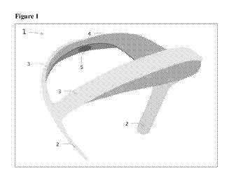
With reference now to the figures, Figure 1 shows a perspective view of an
exemplary
device for capturing and influencing biosignals 1 including two anchors 2 with
two semi-
11
CA 03143130 2021-12-09
WO 2020/250160
PCT/IB2020/055469
flexible bands 3 holding in place a flexible membrane 4 with embedded
biosensors and/or
biostimulators 5.
Figure 2 is a side view of an exemplary device for capturing and influencing
biosignals
1 including two anchors 2 with two semi-flexible bands 3 holding in place a
flexible membrane
4 with embedded biosensors and/or biostimulators.
Figure 3 is a top down view of an exemplary device for capturing and
influencing
biosignals 1 including two anchors 2 with two semi-flexible bands 3 holding in
place a flexible
membrane 4 with embedded biosensors and/or biostimulators 5. Figure 4 provides
additional
elevation views of an exemplary device for capturing and influencing
biosignals.
In Figure 5, the sensor system 100 includes an elastic non-flat sensing
surface 105, with
bump features 101 extending from the core, for contact and/or non-contact
capacitive coupling
to the body 5 through hair or other obstructions 10. The sensing surface 105
is connected to
the amplifier 115.
Figure 6 illustrates an alternative embodiment in which sensor system 200
includes a
guard shield 120 around the elastic non-flat sensing surface 105 for contact
and/or non-contact
capacitive coupling to the body 5 through hair or other obstructions 10. The
sensing surface
105 is connected to the amplifier 115.
In Figure 7, the sensor system 100 includes an elastic non-flat sensing
surface 105 for
contact and/or non-contact capacitive coupling to the body 5 through hair or
other obstructions
10. The sensing surface 105 is connected to the amplifier 115. In this figure
the sensing surface
105 is show compressed against and conforming to the shape of the body 5.
In Figure 8, the sensor system 100 includes an elastic non-flat sensing
surface 105,
without additional features extending from the core, for contact and/or non-
contact capacitive
coupling to the body 5 through hair or other obstructions 10. The sensing
surface 105 is
connected to the amplifier 115.
Figure 9 provides a flow chart of a sensing protocol methodology according to
an
embodiment of the present invention. The protocol starts at 300 where the
elastic non-flat
sensing surface is placed inside the electric field of a body. In 305 the
sensing surface couples
to the electric field generated by the body and adapts to changing conditions
before 310 being
amplified and converted into a digital signal.
12
CA 03143130 2021-12-09
WO 2020/250160
PCT/IB2020/055469
As can be understood, the examples described above and illustrated in the
figures are
intended to be exemplary only. The scope is indicated by the appended claims.
13