Note: Descriptions are shown in the official language in which they were submitted.
CA 03143303 2021-12-10
WO 2021/133614 PCT/US2020/065383
HEART VALVE SEALING DEVICES AND DELIVERY DEVICES THEREFOR
RELATED APPLICATIONS
[0001] The present application claims the benefit of U.S. provisional
application
no. 62/953,098 filed on December 23, 2019, which is incorporated herein by
reference in its entirety for all purposes.
BACKGROUND OF THE INVENTION
[0002] The native heart valves (i.e., the aortic, pulmonary, tricuspid, and
mitral
valves) serve critical functions in assuring the forward flow of an adequate
supply
of blood through the cardiovascular system. These heart valves can be damaged,
and thus rendered less effective, for example, by congenital malformations,
inflammatory processes, infectious conditions, disease, etc. Such damage to
the
valves can result in serious cardiovascular compromise or death. Damaged
valves
can be surgically repaired or replaced during open heart surgery. However,
open
heart surgeries are highly invasive, and complications may occur.
Transvascular
techniques can be used to introduce and implant prosthetic devices in a manner
that is much less invasive than open heart surgery. As one example, a
transvascular technique useable for accessing the native mitral and aortic
valves
is the trans-septal technique. The trans-septal technique comprises advancing
a
catheter into the right atrium (e.g., inserting a catheter into the right
femoral vein,
up the inferior vena cava and into the right atrium). The septum is then
punctured, and the catheter passed into the left atrium. A similar
transvascular
technique can be used to implant a prosthetic device within the tricuspid
valve
that begins similarly to the trans-septal technique but stops short of
puncturing
the septum and instead turns the delivery catheter toward the tricuspid valve
in
the right atrium.
[0003] A healthy heart has a generally conical shape that tapers to a lower
apex.
The heart is four-chambered and comprises the left atrium, right atrium, left
ventricle, and right ventricle. The left and right sides of the heart are
separated by
a wall generally referred to as the septum. The native mitral valve of the
human
heart connects the left atrium to the left ventricle. The mitral valve has a
very
different anatomy than other native heart valves. The mitral valve includes an
annulus portion, which is an annular portion of the native valve tissue
surrounding the mitral valve orifice, and a pair of cusps, or leaflets,
extending
downward from the annulus into the left ventricle. The mitral valve annulus
can
1
CA 03143303 2021-12-10
WO 2021/133614 PCT/US2020/065383
form a "D"-shaped, oval, or otherwise out-of-round cross-sectional shape
having
major and minor axes. The anterior leaflet can be larger than the posterior
leaflet,
forming a generally "C"-shaped boundary between the abutting sides of the
leaflets
when they are closed together.
[0004] When operating properly, the anterior leaflet and the posterior leaflet
function together as a one-way valve to allow blood to flow only from the left
atrium to the left ventricle. The left atrium receives oxygenated blood from
the
pulmonary veins. When the muscles of the left atrium contract and the left
ventricle dilates (also referred to as "ventricular diastole" or "diastole"),
the
oxygenated blood that is collected in the left atrium flows into the left
ventricle.
When the muscles of the left atrium relax and the muscles of the left
ventricle
contract (also referred to as "ventricular systole" or "systole"), the
increased blood
pressure in the left ventricle urges the sides of the two leaflets together,
thereby
closing the one-way mitral valve so that blood cannot flow back to the left
atrium
and is instead expelled out of the left ventricle through the aortic valve. To
prevent
the two leaflets from prolapsing under pressure and folding back through the
mitral annulus toward the left atrium, a plurality of fibrous cords called
chordae
tendineae tether the leaflets to papillary muscles in the left ventricle.
[0005] Valvular regurgitation involves the valve improperly allowing some
blood to
flow in the wrong direction through the valve. For example, mitral
regurgitation
occurs when the native mitral valve fails to close properly and blood flows
into the
left atrium from the left ventricle during the systolic phase of heart
contraction.
Mitral regurgitation is one of the most common forms of valvular heart
disease.
Mitral regurgitation can have many different causes, such as leaflet prolapse,
dysfunctional papillary muscles, stretching of the mitral valve annulus
resulting
from dilation of the left ventricle, more than one of these, etc. Mitral
regurgitation
at a central portion of the leaflets can be referred to as central jet mitral
regurgitation and mitral regurgitation nearer to one commissure (i.e.,
location
where the leaflets meet) of the leaflets can be referred to as eccentric jet
mitral
regurgitation. Central jet regurgitation occurs when the edges of the leaflets
do not
meet in the middle and thus the valve does not close, and regurgitation is
present.
SUMMARY
[0006] This summary is meant to provide some examples and is not intended to
be
limiting of the scope of the invention in any way. For example, any feature
2
CA 03143303 2021-12-10
WO 2021/133614 PCT/US2020/065383
included in an example of this summary is not required by the claims, unless
the
claims explicitly recite the features. Also, the features, components, steps,
concepts, etc. described in examples in this summary and elsewhere in this
disclosure can be combined in a variety of ways. Various features and steps as
described elsewhere in this disclosure may be included in the examples
summarized here.
[0007] A native valve of a patient can be repaired by attaching a spacer
between
leaflets of the native valve of the patient. Retrograde blood flow through
gaps
between the spacer and the leaflets is blocked or inhibited.
[0008] An example valve repair device includes a spacer, a pair of paddles,
and at
least one leak control extension. The pair of anchors (e.g., paddles, latches,
clamps, grippers, fasteners, etc.) can be coupled to the spacer. The pair of
anchors
(e.g., a pair of paddles) are movable between an open position and a closed
position
and are configured to attach the valve repair device to the native valve of
the
patient. The at least one leak control extension extends from the spacer and
is
configured to block retrograde blood flow along sides of the spacer.
[0009] An example valve repair system includes a delivery sheath and a valve
repair device. The valve repair device is deployable to the native valve of
the
patient by the delivery sheath. The valve repair device includes a spacer, a
pair of
paddles, and at least one leak control extension. The pair of paddles are
coupled to
the spacer. The pair of paddles are movable between an open position and a
closed
position and are configured to attach the valve repair device to the native
valve of
the patient. The at least one leak control extension extends from the spacer
and is
configured to block retrograde blood flow along sides of the spacer.
[0010] In some implementations, a valve repair device for repairing a native
valve
of a patient comprises a spacer, a pair of anchors (e.g., paddles, latches,
clamps,
grippers, fasteners, etc.) configured to attach the valve repair device to the
native
valve of the patient, and at least one leak control extension extending from
the
spacer.
[0011] In some implementations, the pair of anchors are a pair of paddles
coupled
to the spacer. In some implementations, the pair of paddles are movable
between
an open position and a closed position.
3
CA 03143303 2021-12-10
WO 2021/133614
PCT/US2020/065383
[0012] In some implementations, the at least one leak control extension
extends
from the spacer. The leak control extension is configured to block retrograde
blood
flow along sides of the spacer.
[0013] In some implementations, the valve repair device further comprises a
cap
that is connected to the spacer. In some implementations, the at least one
leak
control extension is connected to the cap that is connected to the spacer. In
some
implementations, the at least one leak control extension is pivotally attached
to
the cap. In some implementations, the at least one leak control extension is
connected directly to the spacer.
[0014] In some implementations, the valve repair device further comprises a
pair
of clasps, wherein the pair of anchors (e.g., a pair of paddles) and the pair
of clasps
are configured to attach the valve repair device to the native valve of the
patient.
[0015] In some implementations, the spacer is configured to close a gap in the
native valve of the patient when the valve repair device is attached to the
native
valve.
[0016] In some implementations, the at least one leak control extension
comprises
a deflector paddle having a flexible wire frame covered by a cloth barrier
material.
The deflector paddle can be connected to the spacer by one or more arms.
[0017] In some implementations, the flexible wire frame is configured to
deform
when positioned against a wall within the heart of the patient.
[0018] In some implementations, the at least one leak control extension
comprises
a pocket that includes a flexible wire frame that defines an opening of the
pocket
and a cloth barrier material that defines at least a portion of the interior
of the
pocket. In some implementations, the opening of the at least one leak control
extension is configured to be positioned below one or more leaflets of the
native
valve when the valve repair device is attached to the native valve. In some
implementations, the opening of the at least one leak control extension is
configured to be positioned above a ventricular end of the one or more
leaflets of
the native valve when the valve repair device is attached to the native valve.
4
CA 03143303 2021-12-10
WO 2021/133614 PCT/US2020/065383
[0019] In some implementations, at least a portion of the leak control
extension is
configured to be positioned below a ventricular end of one or more leaflets of
the
native valve when the valve repair device is attached to the native valve.
[0020] In some implementations, the entire leak control extension is
configured to
be positioned above a ventricular end of one or more leaflets of the native
valve
when the valve repair device is attached to the native valve. In some
implementations, the entire leak control extension is configured to be
positioned
below a ventricular end of one or more leaflets of the native valve when the
valve
repair device is attached to the native valve.
[0021] In some implementations, the at least one leak control extension
comprises
one or more deflector paddles and a barrier element. In some implementations,
each of the one or more deflector paddles has a flexible wire frame covered by
a
cloth barrier material. In some implementations, the barrier element comprises
at
least one of a cloth material, a biocompatible material, bovine or porcine
heart
tissue, and a plastic membrane.
[0022] In some implementations, a valve repair device for repairing a native
valve
comprises at least one anchor (e.g., a paddle, latch, clamp, gripper,
fastener, etc.)
configured to attach the valve repair device to the native valve of the
patient and
at least one leak control extension extending from a portion of the valve
repair
device.
[0023] In some implementations, the at least one anchor is movable between an
open position and a closed position.
[0024] In some implementations, the at least one leak control extension is
configured to block retrograde blood flow adjacent or near the device.
[0025] In some implementations, the valve repair device further comprises a
coaption element (e.g., coaptation element, spacer, etc.). The coaption
element is
configured to close a gap in the native valve of the patient when the valve
repair
device is attached to the native valve. In some implementations, the at least
one
leak control extension extends from the coaption element and is configured to
block
retrograde blood flow along sides of the coaption element.
CA 03143303 2021-12-10
WO 2021/133614 PCT/US2020/065383
[0026] In some implementations, the valve repair device further comprises a
cap
that is connected to the coaption element. In some implementations, the at
least
one leak control extension is connected directly to the coaption element. In
some
implementations, the at least one leak control extension is connected to the
cap
that is connected to the coaption element. In some implementations, the at
least
one leak control extension is pivotally attached to the cap.
[0027] In some implementations, the at least one anchor is coupled to the
coaption
element. In some implementations, the at least one anchor comprises a pair of
paddles coupled to the coaption element.
[0028] In some implementations, the at least one anchor comprises a pair of
paddles.
[0029] In some implementations, the valve repair device further comprises at
least
one clasp, wherein the at least one anchor and the at least one clasp are
configured
to attach the valve repair device to the native valve of the patient.
[0030] In some implementations, the at least one clasp is coupled to a cap of
the
device.
[0031] In some implementations, the at least one leak control extension
comprises
a deflector paddle having a flexible wire frame covered by a cloth barrier
material.
In some implementations, the deflector paddle is connected to the spacer by
one or
more arms. In some implementations, the flexible wire frame is configured to
deform when positioned against a wall within the native valve of the patient.
[0032] In some implementations, the at least one leak control extension
comprises
a pocket that includes a flexible wire frame that defines an opening of the
pocket
and a cloth barrier material that defines at least a portion of the interior
of the
pocket. In some implementations, the opening of the at least one leak control
extension is configured to be positioned below one or more leaflets of the
native
valve when the valve repair device is attached to the native valve. In some
implementations, the opening of the at least one leak control extension is
configured to be positioned above a ventricular end of the one or more
leaflets of
the native valve when the valve repair device is attached to the native valve.
6
CA 03143303 2021-12-10
WO 2021/133614 PCT/US2020/065383
[0033] In some implementations, at least a portion of the leak control
extension is
configured to be positioned below a ventricular end of one or more leaflets of
the
native valve when the valve repair device is attached to the native valve. In
some
implementations, the entire leak control extension is configured to be
positioned
above a ventricular end of one or more leaflets of the native valve when the
valve
repair device is attached to the native valve. In some implementations, the
entire
leak control extension is configured to be positioned below a ventricular end
of one
or more leaflets of the native valve when the valve repair device is attached
to the
native valve.
[0034] In some implementations, the at least one leak control extension
comprises
one or more deflector paddles and a barrier element. In some implementations,
the
one or more deflector paddles has a flexible wire frame covered by a cloth
barrier
material. In some implementations, the barrier element comprises at least one
of a
cloth material, a biocompatible material, bovine or porcine heart tissue, and
a
plastic membrane.
[0035] In some implementations, a valve repair system for repairing a native
valve
of a patient comprises a delivery sheath and a valve repair device that is
deployable to a native valve of the patient by the delivery sheath.
[0036] In some implementations, the valve repair device comprises a coaption
element or spacer, a pair of paddles (or other anchors) coupled to the
spacer/coaption element, and at least one leak control extension extending
from
the spacer/coaption element, wherein the leak control extension is configured
to
block retrograde blood flow along sides of the spacer/coaption element.
[0037] In some implementations, the pair of paddles (or other anchors) are
movable between an open position and a closed position, wherein the pair of
paddles (or other anchors) are configured to attach the valve repair device to
the
native valve of the patient.
[0038] In some implementations, the system (e.g., the valve repair device of
the
system) further comprises a cap that is connected to the spacer/coaption
element.
In some implementations, the at least one leak control extension is connected
to
the cap that is connected to the spacer/coaption element. In some
implementations,
the at least one leak control extension is pivotally attached to the cap.
7
CA 03143303 2021-12-10
WO 2021/133614 PCT/US2020/065383
[0039] In some implementations, the at least one leak control extension is
connected directly to the spacer/coaption element.
[0040] In some implementations, the system (e.g., the valve repair device of
the
system) further comprises pair of clasps, wherein the pair of paddles (or
other
anchors) and the pair of clasps are configured to attach the valve repair
device to
the native valve of the patient.
[0041] In some implementations, the spacer/coaption element is configured to
close
a gap in the native valve of the patient when the valve repair device is
attached to
the native valve.
[0042] In some implementations, the at least one leak control extension
comprises
a deflector paddle having a flexible wire frame covered by a cloth barrier
material.
In some implementations, the deflector paddle is connected to the spacer by
one or
more arms. In some implementations, the flexible wire frame is configured to
deform when positioned against a wall within the heart of the patient.
[0043] In some implementations, the at least one leak control extension
comprises
a pocket that includes a flexible wire frame that defines an opening of the
pocket
and a cloth barrier material that defines at least a portion of the interior
of the
pocket. In some implementations, the opening of the at least one leak control
extension is configured to be positioned below one or more leaflets of the
native
valve when the valve repair device is attached to the native valve. In some
implementations, the opening of the at least one leak control extension is
configured to be positioned above a ventricular end of the one or more
leaflets of
the native valve when the valve repair device is attached to the native valve.
[0044] In some implementations, at least a portion of the leak control
extension is
configured to be positioned below a ventricular end of one or more leaflets of
the
native valve when the valve repair device is attached to the native valve.
[0045] In some implementations, the entire leak control extension is
configured to
be positioned above a ventricular end of one or more leaflets of the native
valve
when the valve repair device is attached to the native valve. In some
implementations, the entire leak control extension is configured to be
positioned
below a ventricular end of one or more leaflets of the native valve when the
valve
repair device is attached to the native valve.
8
CA 03143303 2021-12-10
WO 2021/133614 PCT/US2020/065383
[0046] In some implementations, the at least one leak control extension
comprises
one or more deflector paddles and a barrier element. In some implementations,
each of the one or more deflector paddles has a flexible wire frame covered by
a
cloth barrier material. In some implementations, the barrier element comprises
at
least one of a cloth material, a biocompatible material, bovine or porcine
heart
tissue, and a plastic membrane.
[0047] In some implementations, a valve repair system for repairing a native
valve
of a patient comprises a delivery sheath and a valve repair device that is
deployable to a native valve of the patient by the delivery sheath;
[0048] In some implementations, the valve repair device comprises at least one
anchor (e.g., a paddle, latch, clamp, gripper, fastener, etc.) and at least
one leak
control extension extending from a portion of the device, wherein the leak
control
extension is configured to block retrograde blood flow adjacent or near the
device.
[0049] In some implementations, the at least one anchor is movable between an
open position and a closed position, wherein the pair of paddles are
configured to
attach the valve repair device to the native valve of the patient;
[0050] In some implementations, the system (e.g., the valve repair device of
the
system) further comprises a coaption element (e.g., spacer, coaptation
element,
etc.).
[0051] In some implementations, the at least one leak control extension
extends
from the coaption element and is configured to block retrograde blood flow
along
sides of the coaption element.
[0052] In some implementations, the system (e.g., the valve repair device of
the
system) further comprises a cap that is connected to the coaption element.
[0053] In some implementations, the at least one leak control extension is
connected directly to the coaption element.
[0054] In some implementations, the at least one leak control extension is
connected to the cap that is connected to the coaption element.
[0055] In some implementations, the at least one leak control extension is
pivotally
attached to the cap.
9
CA 03143303 2021-12-10
WO 2021/133614 PCT/US2020/065383
[0056] In some implementations, the at least one anchor is coupled to the
coaption
element. In some implementations, the at least one anchor comprises a pair of
paddles coupled to the coaption element.
[0057] In some implementations, the at least one anchor comprises a pair of
paddles.
[0058] In some implementations, the coaption element is configured to close a
gap
in the native valve of the patient when the valve repair device is attached to
the
native valve.
[0059] In some implementations, the system further comprises at least one pair
clasp, wherein the at least one anchor and the at least one clasp are
configured to
attach the valve repair device to the native valve of the patient. In some
implementations, the at least one clasp is coupled to a cap of the device.
[0060] In some implementations, the at least one leak control extension
comprises
a deflector paddle having a flexible wire frame covered by a cloth barrier
material.
In some implementations, the deflector paddle is connected to the coaption
element
by one or more arms. In some implementations, the flexible wire frame is
configured to deform when positioned against a wall within the native valve of
the
patient.
[0061] In some implementations, the at least one leak control extension
comprises
a pocket that includes a flexible wire frame that defines an opening of the
pocket
and a cloth barrier material that defines at least a portion of the interior
of the
pocket.
[0062] In some implementations, the opening of the at least one leak control
extension is configured to be positioned below one or more leaflets of the
native
valve when the valve repair device is attached to the native valve.
[0063] In some implementations, the opening of the at least one leak control
extension is configured to be positioned above a ventricular end of the one or
more
leaflets of the native valve when the valve repair device is attached to the
native
valve.
CA 03143303 2021-12-10
WO 2021/133614 PCT/US2020/065383
[0064] In some implementations, at least a portion of the leak control
extension is
configured to be positioned below a ventricular end of one or more leaflets of
the
native valve when the valve repair device is attached to the native valve.
[0065] In some implementations, the entire leak control extension is
configured to
be positioned above a ventricular end of one or more leaflets of the native
valve
when the valve repair device is attached to the native valve. In some
implementations, the entire leak control extension is configured to be
positioned
below a ventricular end of one or more leaflets of the native valve when the
valve
repair device is attached to the native valve.
[0066] In some implementations, the at least one leak control extension
comprises
one or more deflector paddles and a barrier element. In some implementations,
each of the one or more deflector paddles has a flexible wire frame covered by
a
cloth barrier material. In some implementations, the barrier element comprises
at
least one of a cloth material, a biocompatible material, bovine or porcine
heart
tissue, and a plastic membrane.
[0067] In some implementations, a method of repairing a native valve of a
patient
comprises attaching a spacer or coaption element between leaflets of the
native
valve of the patient and blocking retrograde blood flow through gaps between
the
spacer and the leaflets.
[0068] In some implementations, the retrograde blood flow through the gaps is
blocked without filling the gaps.
[0069] In some implementations, the retrograde blood flow through the gaps is
blocked without filling any portion of the gaps.
[0070] In some implementations, the retrograde blood flow is blocked by
extensions
that are at least partially disposed on a ventricular side of the leaflets.
[0071] In some implementations, the retrograde blood flow is blocked by
extensions
that are completely disposed on a ventricular side of the leaflets.
[0072] In some implementations, the method further comprises positioning the
spacer to deform one or more of the extensions against a wall within the heart
of
the patient.
11
CA 03143303 2021-12-10
WO 2021/133614 PCT/US2020/065383
[0073] The above method(s) can be performed on a living animal or on a
simulation, such as on a cadaver, cadaver heart, simulator (e.g. with the body
parts, heart, tissue, etc. being simulated), etc.
[0074] A further understanding of the nature and advantages of the present
invention are set forth in the following description and claims, particularly
when
considered in conjunction with the accompanying drawings in which like parts
bear like reference numerals.
BRIEF DESCRIPTION OF THE DRAWINGS
[0075] To further clarify various aspects of embodiments of the present
disclosure,
a more particular description of example embodiments will be made by reference
to
various aspects of the appended drawings. It is appreciated that these
drawings
depict only typical embodiments of the present disclosure and are therefore
not to
be considered limiting of the scope of the disclosure. Moreover, while the
figures
can be drawn to scale for some embodiments, the figures are not necessarily
drawn
to scale for all embodiments. Embodiments and other features and advantages of
the present disclosure will be described and explained with additional
specificity
and detail through the use of the accompanying drawings in which:
[0076] Figure 1 illustrates a cutaway view of the human heart in a diastolic
phase;
[0077] Figure 2 illustrates a cutaway view of the human heart in a systolic
phase;
[0078] Figure 3 illustrates a cutaway view of the human heart in a diastolic
phase,
in which the chordae tendineae are shown attaching the leaflets of the mitral
and
tricuspid valves to ventricle walls;
[0079] Figure 4 illustrates a healthy mitral valve with the leaflets closed as
viewed
from an atrial side of the mitral valve;
[0080] Figure 5 illustrates a dysfunctional mitral valve with a visible gap
between
the leaflets as viewed from an atrial side of the mitral valve;
[0081] Figure 6 illustrates a mitral valve having a wide gap between the
posterior
leaflet and the anterior leaflet;
[0082] Figure 7 illustrates a tricuspid valve viewed from an atrial side of
the
tricuspid valve;
12
CA 03143303 2021-12-10
WO 2021/133614 PCT/US2020/065383
[0083] Figures 8-14 show an example of an implantable prosthetic device, in
various stages of deployment;
[0084] Figures 15-20 show the implantable prosthetic device of Figures 8-14
being
delivered and implanted within a native valve;
[0085] Figure 21 shows the implantable prosthetic device of Figures 8-14
implanted within a native valve;
[0086] Figure 22 shows an implantable prosthetic device implanted in a first
example position within a native valve;
[0087] Figure 23 is a cross-sectional view of the implantable prosthetic
device
implanted in the first position within the native valve shown in Figure 22,
with
the section taken along the plane indicated by line 23-23 in Figure 22;
[0088] Figure 24 shows the implantable prosthetic device implanted in the
first
position within the native valve shown in Figure 22, viewed from the ventricle
side
of the native valve;
[0089] Figure 25 shows the implantable prosthetic device implanted in the
first
position within the native valve shown in Figure 22, viewed from the atrial
side of
the native valve;
[0090] Figure 26 shows the implantable prosthetic device of Figure 22
implanted in
a second example position within the native valve, viewed from the ventricle
side
of the native valve;
[0091] Figure 27 shows the implantable prosthetic device of Figure 22
implanted in
the second example position within the native valve shown in Figure 26, viewed
from the atrial side of the native valve;
[0092] Figure 28 shows an example of an implantable prosthetic device
implanted
in a first example position within the native valve;
[0093] Figure 29 is a cross-sectional view of the implantable prosthetic
device
implanted in the first position within the native valve shown in Figure 28,
with
the section taken along the plane indicated by line 29-29 in Figure 28;
13
CA 03143303 2021-12-10
WO 2021/133614 PCT/US2020/065383
[0094] Figure 30 shows the implantable prosthetic device implanted in the
first
position within the valve shown in Figure 28, viewed when the heart is in a
diastolic phase;
[0095] Figure 31 is a cross-sectional view of the implantable prosthetic
device
implanted in the first position within the native valve shown in Figure 30,
with
the section taken along the plane indicated by line 31-31 shown in Figure 30;
[0096] Figure 32 shows the implantable prosthetic device implanted in the
first
position within the valve shown in Figure 28, viewed when the heart is in a
systolic phase;
[0097] Figure 33 is a cross-sectional view of the implantable prosthetic
device
implanted in the first position within the native valve shown in Figure 32,
with
the section taken along the plane indicated by line 33-33 shown in Figure 32;
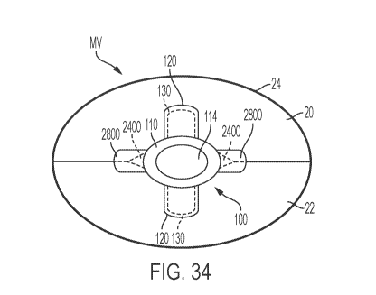
[0098] Figure 34 shows the implantable prosthetic device implanted in the
first
position within the native valve shown in Figure 28, viewed from a ventricle
side of
the native valve;
[0099] Figure 35 shows the implantable prosthetic device implanted in the
first
position within the native valve shown in Figure 28, viewed from an atrial
side of
the native valve;
[0100] Figure 36 shows the implantable prosthetic device of Figure 28
implanted in
a second example position within the native valve, viewed from the ventricle
side
of the native valve;
[0101] Figure 37 shows the implantable prosthetic device of Figure 28
implanted in
the second example position within the native valve shown in Figure 36, viewed
from the atrial side of the native valve;
[0102] Figure 38A shows an example of an implantable prosthetic device
implanted in a first example position within the native valve;
[0103] Figure 38B shows an example of an implantable prosthetic device
implanted in a first example position within the native valve;
14
CA 03143303 2021-12-10
WO 2021/133614
PCT/US2020/065383
[0104] Figure 39A is a cross-sectional view of the implantable prosthetic
device
implanted in the first position within the native valve shown in Figure 38A,
with
the section taken along the plane indicated by line 39A-39A in Figure 38A;
[0105] Figure 39B is a cross-sectional view of the implantable prosthetic
device
implanted in the first position within the native valve shown in Figure 38B,
with
the section taken along the plane indicated by line 39B-39B in Figure 38B;
[0106] Figure 40A shows the implantable prosthetic device implanted in the
first
position within the native valve shown in Figure 38A, viewed when the heart is
in
a diastolic phase;
[0107] Figure 40B shows the implantable prosthetic device implanted in the
first
position within the native valve shown in Figure 38B, viewed when the heart is
in
a diastolic phase;
[0108] Figure 41A is a cross-sectional view of the implantable prosthetic
device
implanted in the first position within the native valve shown in Figure 40A,
with
the section taken along the plane indicated by line 41A-41A shown in Figure
40A;
[0109] Figure 41B is a cross-sectional view of the implantable prosthetic
device
implanted in the first position within the native valve shown in Figure 40B,
with
the section taken along the plane indicated by line 41B-41B shown in Figure
40B;
[0110] Figure 42A shows the implantable prosthetic device implanted in the
first
position within the native valve shown in Figure 38A, viewed when the heart is
in
a systolic phase;
[0111] Figure 42B shows the implantable prosthetic device implanted in the
first
position within the native valve shown in Figure 38B, viewed when the heart is
in
a systolic phase;
[0112] Figure 43A is a cross-sectional view of the implantable prosthetic
device
implanted in the first position within the native valve shown in Figure 42A,
with
the section taken along the plane indicated by line 43A-43A shown in Figure
42A;
[0113] Figure 43B is a cross-sectional view of the implantable prosthetic
device
implanted in the first position within the native valve shown in Figure 42B,
with
the section taken along the plane indicated by line 43B-43B shown in Figure
42B;
CA 03143303 2021-12-10
WO 2021/133614 PCT/US2020/065383
[0114] Figure 44A shows the implantable prosthetic device implanted in the
first
position within the native valve shown in Figure 38A, viewed from a ventricle
side
of the native valve;
[0115] Figure 44B shows the implantable prosthetic device implanted in the
first
position within the native valve shown in Figure 38B, viewed from a ventricle
side
of the native valve;
[0116] Figure 45A shows the implantable prosthetic device implanted in the
first
position within the native valve shown in Figure 38A, viewed from an atrial
side of
the native valve;
[0117] Figure 45B shows the implantable prosthetic device implanted in the
first
position within the native valve shown in Figure 38B, viewed from an atrial
side of
the native valve;
[0118] Figure 46A shows the implantable prosthetic device of Figure 38A
implanted in a second example position within the native valve, viewed from
the
ventricle side of the native valve;
[0119] Figure 46B shows the implantable prosthetic device of Figure 38B
implanted in a second example position within the native valve, viewed from
the
ventricle side of the native valve;
[0120] Figure 47A shows the implantable prosthetic device of Figure 38A
implanted in the second example position within the mitral valve shown in
Figure
46A, viewed from the atrial side of the native valve;
[0121] Figure 47B shows the implantable prosthetic device of Figure 38B
implanted in the second example position within the mitral valve shown in
Figure
46B, viewed from the atrial side of the native valve;
[0122] Figure 48A shows an example of an implantable prosthetic device
implanted in a first example position within the native valve;
[0123] Figure 48B shows an example of an implantable prosthetic device
implanted in a first example position within the native valve;
16
CA 03143303 2021-12-10
WO 2021/133614
PCT/US2020/065383
[0124] Figure 49A is a cross-sectional view of the implantable prosthetic
device
implanted in the first position within the native valve shown in Figure 48A,
with
the section taken along the plane indicated by line 49A-49A in Figure 48A;
[0125] Figure 49B is a cross-sectional view of the implantable prosthetic
device
implanted in the first position within the native valve shown in Figure 48B,
with
the section taken along the plane indicated by line 49B-49B in Figure 48B;
[0126] Figure 50A shows the implantable prosthetic device implanted in the
first
position within the native valve shown in Figure 48A, viewed when the heart is
in
a diastolic phase;
[0127] Figure 50B shows the implantable prosthetic device implanted in the
first
position within the native valve shown in Figure 48B, viewed when the heart is
in
a diastolic phase;
[0128] Figure 51A is a cross-sectional view of the implantable prosthetic
device
implanted in the first position within the native valve shown in Figure 50A,
with
the section taken along the plane indicated by line 51A-51A shown in Figure
50A;
[0129] Figure 51B is a cross-sectional view of the implantable prosthetic
device
implanted in the first position within the native valve shown in Figure 50B,
with
the section taken along the plane indicated by line 51B-51B shown in Figure
50B;
[0130] Figure 52A shows the implantable prosthetic device implanted in the
first
position within the native valve shown in Figure 48A, viewed when the heart is
in
a systolic phase;
[0131] Figure 52B shows the implantable prosthetic device implanted in the
first
position within the native valve shown in Figure 48B, viewed when the heart is
in
a systolic phase;
[0132] Figure 53A is a cross-sectional view of the implantable prosthetic
device
implanted in the first position within the native valve shown in Figure 52A,
with
the section taken along the plane indicated by line 53A-53A shown in Figure
52A;
[0133] Figure 53B is a cross-sectional view of the implantable prosthetic
device
implanted in the first position within the native valve shown in Figure 52B,
with
the section taken along the plane indicated by line 53B-53B shown in Figure
52B;
17
CA 03143303 2021-12-10
WO 2021/133614 PCT/US2020/065383
[0134] Figure 54A shows the implantable prosthetic device implanted in the
first
position within the native valve shown in Figure 48A, viewed from a ventricle
side
of the native valve;
[0135] Figure 54B shows the implantable prosthetic device implanted in the
first
position within the native valve shown in Figure 48B, viewed from a ventricle
side
of the native valve;
[0136] Figure 55A shows the implantable prosthetic device implanted in the
first
position within the native valve shown in Figure 48A, viewed from an atrial
side of
the native valve;
[0137] Figure 55B shows the implantable prosthetic device implanted in the
first
position within the native valve shown in Figure 48B, viewed from an atrial
side of
the native valve;
[0138] Figure 56A shows the implantable prosthetic device of Figure 48A
implanted in a second example position within the native valve, viewed from
the
ventricle side of the native valve;
[0139] Figure 56B shows the implantable prosthetic device of Figure 48B
implanted in a second example position within the native valve, viewed from
the
ventricle side of the native valve;
[0140] Figure 57A shows the implantable prosthetic device of Figure 48A
implanted in the second example position within the native valve shown in
Figure
56A, viewed from the atrial side of the native valve;
[0141] Figure 57B shows the implantable prosthetic device of Figure 48B
implanted in the second example position within the native valve shown in
Figure
56B, viewed from the atrial side of the native valve;
[0142] Figure 58 shows an example of an implantable prosthetic device
implanted
in a first example position within the native valve;
[0143] Figure 59 is a cross-sectional view of the implantable prosthetic
device
implanted in the first position within the native valve shown in Figure 58,
with
the section taken along the plane indicated by line 59-59 in Figure 58;
18
CA 03143303 2021-12-10
WO 2021/133614 PCT/US2020/065383
[0144] Figure 60 shows the implantable prosthetic device implanted in the
first
position within the native valve shown in Figure 58, viewed when the heart is
in a
diastolic phase;
[0145] Figure 61 is a cross-sectional view of the implantable prosthetic
device
implanted in the first position within the native valve shown in Figure 60,
with
the section taken along the plane indicated by line 61-61 shown in Figure 60;
[0146] Figure 62 shows the implantable prosthetic device implanted in the
first
position within the native valve shown in Figure 58, viewed when the heart is
in a
systolic phase;
[0147] Figure 63 is a cross-sectional view of the implantable prosthetic
device
implanted in the first position within the native valve shown in Figure 62,
viewed
along the line 63-63 shown in Figure 62;
[0148] Figure 64 shows the implantable prosthetic device implanted in the
first
position within the native valve shown in Figure 58, viewed from a ventricle
side of
the native valve;
[0149] Figure 65 shows the implantable prosthetic device implanted in the
first
position within the native valve shown in Figure 58, viewed from an atrial
side of
the native valve;
[0150] Figure 66 shows the implantable prosthetic device of Figure 58
implanted in
a second example position within the native valve, viewed from the ventricle
side
of the native valve;
[0151] Figure 67 shows the implantable prosthetic device of Figure 58
implanted in
the second example position within the native valve shown in Figure 66, viewed
from the atrial side of the native valve;
[0152] Figure 68 shows an example of an implantable prosthetic device
implanted
in a first example position within the native valve;
[0153] Figure 69 is a cross-sectional view of the implantable prosthetic
device
implanted in the first position within the native valve shown in Figure 68,
with
the section taken along the plane indicated by line 69-69 in Figure 68;
19
CA 03143303 2021-12-10
WO 2021/133614 PCT/US2020/065383
[0154] Figure 70 shows the implantable prosthetic device implanted in the
first
position within the valve shown in Figure 68, viewed when the heart is in a
diastolic phase;
[0155] Figure 71 is a cross-sectional view of the implantable prosthetic
device
implanted in the first position within the native valve shown in Figure 70,
with
the section taken along the plane indicated by line 71-71 shown in Figure 70;
[0156] Figure 72 shows the implantable prosthetic device implanted in the
first
position within the valve shown in Figure 68, viewed when the heart is in a
systolic phase;
[0157] Figure 73 is a cross-sectional view of the implantable prosthetic
device
implanted in the first position within the native valve shown in Figure 72,
with
the section taken along the plane indicated by line 73-73 shown in Figure 72;
[0158] Figure 74 shows the implantable prosthetic device implanted in the
first
position within the native valve shown in Figure 68, viewed from a ventricle
side of
the native valve;
[0159] Figure 75 shows the implantable prosthetic device implanted in the
first
position within the native valve shown in Figure 68, viewed from an atrial
side of
the native valve;
[0160] Figure 76 shows the implantable prosthetic device of Figure 68
implanted in
a second example position within the native valve, viewed from the ventricle
side
of the native valve;
[0161] Figure 77 shows the implantable prosthetic device of Figure 68
implanted in
the second example position within the native valve shown in Figure 76, viewed
from the atrial side of the native valve;
[0162] Figure 78 is a bottom view of a more specific example of the
implantable
prosthetic device shown in Figures 38A-47A;
[0163] Figure 79 is a bottom view of a more specific example of the
implantable
prosthetic device shown in Figures 38A-47A;
CA 03143303 2021-12-10
WO 2021/133614 PCT/US2020/065383
[0164] Figure 80 is a front view of a more specific example of the implantable
prosthetic device shown in Figures 48A-57A;
[0165] Figure 81 is a bottom view of the implantable prosthetic device shown
in
Figure 80;
[0166] Figure 82 shows an example of an implantable prosthetic device
implanted
in a first example position within the native valve;
[0167] Figure 83 is a cross-sectional view of the implantable prosthetic
device
implanted in the first position within the native valve shown in Figure 82,
with
the section taken along the plane indicated by line 83-83 in Figure 82;
[0168] Figure 84 shows the implantable prosthetic device implanted in the
first
position within the native valve shown in Figure 82, viewed when the heart is
in a
diastolic phase;
[0169] Figure 85 is a cross-sectional view of the implantable prosthetic
device
implanted in the first position within the native valve shown in Figure 84,
with
the section taken along the plane indicated by line 85-85 shown in Figure 84;
[0170] Figure 86 shows the implantable prosthetic device implanted in the
first
position within the native valve shown in Figure 82, viewed when the heart is
in a
systolic phase;
[0171] Figure 87 is a cross-sectional view of the implantable prosthetic
device
implanted in the first position within the native valve shown in Figure 86,
viewed
along the line 87-87 shown in Figure 86;
[0172] Figure 88 shows the implantable prosthetic device implanted in the
first
position within the native valve shown in Figure 82, viewed from a ventricle
side of
the native valve;
[0173] Figure 89 shows the implantable prosthetic device implanted in the
first
position within the native valve shown in Figure 82, viewed from an atrial
side of
the native valve;
21
CA 03143303 2021-12-10
WO 2021/133614 PCT/US2020/065383
[0174] Figure 90 shows the implantable prosthetic device of Figure 82
implanted in
a second example position within the native valve, viewed from the ventricle
side
of the native valve; and
[0175] Figure 91 shows the implantable prosthetic device of Figure 82
implanted in
the second example position within the native valve shown in Figure 90, viewed
from the atrial side of the native valve.
DETAILED DESCRIPTION
[0176] The following description refers to the accompanying drawings, which
illustrate specific embodiments of the present disclosure. Other embodiments
having different structures and operation do not depart from the scope of the
present disclosure.
[0177] Example implementations of the present disclosure are directed to
systems,
devices, methods, etc. for repairing a defective heart valve. It should be
noted that
various embodiments of native valve repair devices, systems for delivery of
native
valve repair devices, and systems for removal of implanted native valve repair
devices are disclosed herein, and any combination of these options can be made
unless specifically excluded. In other words, individual components of the
disclosed
devices and systems can be combined unless mutually exclusive or otherwise
physically impossible. Further, the techniques and methods can be performed on
a
living animal or on a simulation, such as on a cadaver, cadaver heart,
simulator
(e.g. with the body parts, heart, tissue, etc. being simulated), etc.
[0178] As described herein, when one or more components are described as being
connected, joined, affixed, coupled, attached, or otherwise interconnected,
such
interconnection may be direct as between the components or may be indirect
such
as through the use of one or more intermediary components. Also, as described
herein, reference to a "member," "component," or "portion" shall not be
limited to a
single structural member, component, or element but can include an assembly of
components, members, or elements. Also, as described herein, the terms
"substantially" and "about" are defined as at least close to (and includes) a
given
value or state (preferably within 10% of, more preferably within 1% of, and
most
preferably within 0.1% of).
22
CA 03143303 2021-12-10
WO 2021/133614 PCT/US2020/065383
[0179] Figures 1 and 2 are cutaway views of the human heart H in diastolic and
systolic phases, respectively. The right ventricle RV and left ventricle LV
are
separated from the right atrium RA and left atrium LA, respectively, by the
tricuspid valve TV and mitral valve MV; i.e., the atrioventricular valves.
Additionally, the aortic valve AV separates the left ventricle LV from the
ascending aorta AA, and the pulmonary valve PV separates the right ventricle
from the pulmonary artery PA. Each of these valves has flexible leaflets
(e.g.,
leaflets 20, 22 shown in Figures 4 and 5) extending inward across the
respective
orifices that come together or "coapt" in the flow stream to form the one-way,
fluid-
occluding surfaces. The native valve repair systems of the present application
are
described primarily with respect to the mitral valve MV. Therefore, anatomical
structures of the left atrium LA and left ventricle LV will be explained in
greater
detail. However, the devices described herein can also be used in repairing
other
native valves, e.g., the devices can be used in repairing the tricuspid valve
TV, the
aortic valve AV, and the pulmonary valve PV.
[0180] The left atrium LA receives oxygenated blood from the lungs. During the
diastolic phase, or diastole, seen in Figure 1, the blood that was previously
collected in the left atrium LA (during the systolic phase) moves through the
mitral valve MV and into the left ventricle LV by expansion of the left
ventricle
LV. In the systolic phase, or systole, seen in Figure 2, the left ventricle LV
contracts to force the blood through the aortic valve AV and ascending aorta
AA
into the body. During systole, the leaflets of the mitral valve MV close to
prevent
the blood from regurgitating from the left ventricle LV and back into the left
atrium LA, and blood is collected in the left atrium from the pulmonary vein.
In
one example implementation, the devices described by the present application
are
used to repair the function of a defective mitral valve MV. That is, the
devices are
configured to help close the leaflets of the mitral valve to prevent blood
from
regurgitating from the left ventricle LV and back into the left atrium LA.
[0181] Referring now to Figures 1-7, the mitral valve MV includes two
leaflets, the
anterior leaflet 20 and the posterior leaflet 22. The mitral valve MV also
includes
an annulus 24, which is a variably dense fibrous ring of tissues that
encircles the
leaflets 20, 22. Referring to Figure 3, the mitral valve MV is anchored to the
wall
of the left ventricle LV by chordae tendineae 10. The chordae tendineae 10 are
cord-like tendons that connect the papillary muscles 12 (i.e., the muscles
located at
23
CA 03143303 2021-12-10
WO 2021/133614 PCT/US2020/065383
the base of the chordae tendineae and within the walls of the left ventricle)
to the
leaflets 20, 22 of the mitral valve MV. The papillary muscles 12 serve to
limit the
movements of the mitral valve MV and prevent the mitral valve from being
reverted. The mitral valve MV opens and closes in response to pressure changes
in
the left atrium LA and the left ventricle LV. The papillary muscles do not
open or
close the mitral valve MV. Rather, the papillary muscles brace the mitral
valve
MV against the high pressure needed to circulate blood throughout the body.
Together the papillary muscles and the chordae tendineae are known as the
subvalvular apparatus, which functions to keep the mitral valve MV from
prolapsing into the left atrium LA when the mitral valve closes.
[0182] Various disease processes can impair proper function of one or more of
the
native valves of the heart H. These disease processes include degenerative
processes (e.g., Barlow's Disease, fibroelastic deficiency), inflammatory
processes
(e.g., Rheumatic Heart Disease), and infectious processes (e.g.,
endocarditis). In
addition, damage to the left ventricle LV or the right ventricle RV from prior
heart
attacks (i.e., myocardial infarction secondary to coronary artery disease) or
other
heart diseases (e.g., cardiomyopathy) can distort a native valve's geometry,
which
can cause the native valve to dysfunction. However, the vast majority of
patients
undergoing valve surgery, such as surgery to the mitral valve MV, suffer from
a
degenerative disease that causes a malfunction in a leaflet (e.g., leaflets
20, 22) of
a native valve (e.g., the mitral valve MV), which results in prolapse and
regurgitation.
[0183] Generally, a native valve may malfunction in two different ways: (1)
valve
stenosis; and (2) valve regurgitation. Valve stenosis occurs when a native
valve
does not open completely and thereby causes an obstruction of blood flow.
Typically, valve stenosis results from buildup of calcified material on the
leaflets of
a valve, which causes the leaflets to thicken and impairs the ability of the
valve to
fully open to permit forward blood flow.
[0184] The second type of valve malfunction, valve regurgitation, occurs when
the
leaflets of the valve do not close completely thereby causing blood to leak
back into
the prior chamber (e.g., causing blood to leak from the left ventricle to the
left
atrium). There are three mechanisms by which a native valve becomes
regurgitant¨or incompetent¨which include Carpentier's type I, type II, and
type
III malfunctions. A Carpentier type I malfunction involves the dilation of the
24
CA 03143303 2021-12-10
WO 2021/133614 PCT/US2020/065383
annulus such that normally functioning leaflets are distracted from each other
and
fail to form a tight seal (i.e., the leaflets do not coapt properly). Included
in a type I
mechanism malfunction are perforations of the leaflets, as are present in
endocarditis. A Carpentier's type II malfunction involves prolapse of one or
more
leaflets of a native valve above a plane of coaptation. A Carpentier's type
III
malfunction involves restriction of the motion of one or more leaflets of a
native
valve such that the leaflets are abnormally constrained below the plane of the
annulus. Leaflet restriction can be caused by rheumatic disease (Ma) or
dilation of
a ventricle (Tub).
[0185] Referring to Figure 4, when a healthy mitral valve MV is in a closed
position, the anterior leaflet 20 and the posterior leaflet 22 coapt, which
prevents
blood from leaking from the left ventricle LV to the left atrium LA. Referring
to
Figure 5, regurgitation occurs when the anterior leaflet 20 and/or the
posterior
leaflet 22 of the mitral valve MV is displaced into the left atrium LA during
systole. This failure to coapt causes a gap 26 between the anterior leaflet 20
and
the posterior leaflet 22, which allows blood to flow back into the left atrium
LA
from the left ventricle LV during systole. As set forth above, there are
several
different ways that a leaflet (e.g. leaflets 20, 22 of mitral valve MV) may
malfunction, which can thereby lead to regurgitation.
[0186] Referring to Figure 6, in certain situations, the mitral valve MV of a
patient
can have a wide gap 26 between the anterior leaflet 20 and the posterior
leaflet 22
when the mitral valve is in a closed position (i.e., during the systolic
phase). For
example, the gap 26 can have a width W between about 2.5 mm and about 17.5
mm, such as between about 5 mm and about 15 mm, such as between about 7.5
mm and about 12.5 mm, such as about 10 mm. In some situations, the gap 26 can
have a width W greater than 15 mm. In any of the above-mentioned situations, a
valve repair device is desired that is capable of engaging the anterior
leaflet 20
and the posterior leaflet 22 to close the gap 26 and prevent regurgitation of
blood
through the mitral valve MV.
[0187] Although stenosis or regurgitation can affect any valve, stenosis is
predominantly found to affect either the aortic valve AV or the pulmonary
valve
PV, and regurgitation is predominantly found to affect either the mitral valve
MV
or the tricuspid valve TV. Both valve stenosis and valve regurgitation
increase the
workload of the heart H and may lead to very serious conditions if left un-
treated;
CA 03143303 2021-12-10
WO 2021/133614 PCT/US2020/065383
such as endocarditis, congestive heart failure, permanent heart damage,
cardiac
arrest, and ultimately death. Because the left side of the heart (i.e., the
left atrium
LA, the left ventricle LV, the mitral valve MV, and the aortic valve AV) is
primarily responsible for circulating the flow of blood throughout the body,
malfunction of the mitral valve MV or the aortic valve AV is particularly
problematic and often life threatening. Accordingly, because of the
substantially
higher pressures on the left side of the heart, dysfunction of the mitral
valve MV or
the aortic valve AV is much more problematic.
[0188] Malfunctioning native heart valves may either be repaired or replaced.
Repair typically involves the preservation and correction of the patient's
native
valve. Replacement typically involves replacing the patient's native valve
with a
biological or mechanical substitute. Typically, the aortic valve AV and
pulmonary
valve PV are more prone to stenosis. Because stenotic damage sustained by the
leaflets is irreversible, the most conventional treatments for a stenotic
aortic valve
or stenotic pulmonary valve are removal and replacement of the valve with a
surgically implanted heart valve, or displacement of the valve with a
transcatheter
heart valve. The mitral valve MV and the tricuspid valve TV are more prone to
deformation of leaflets, which, as described above, prevents the mitral valve
or
tricuspid valve from closing properly and allows for regurgitation or back
flow of
blood from the ventricle into the atrium (e.g., a deformed mitral valve MV may
allow for regurgitation or back flow from the left ventricle LV to the left
atrium
LA). The regurgitation or back flow of blood from the ventricle to the atrium
results in valvular insufficiency. Deformations in the structure or shape of
the
mitral valve MV or the tricuspid valve TV can be repairable. In addition,
regurgitation can occur due to the chordae tendineae 10 becoming dysfunctional
(e.g., the chordae tendineae may stretch or rupture), which allows the
anterior
leaflet 20 and the posterior leaflet 22 to be reverted such that blood is
regurgitated
into the left atrium LA. The problems occurring due to dysfunctional chordae
tendineae can be repaired by repairing the chordae tendineae or the structure
of
the mitral valve (e.g., by securing the leaflets 20, 22 at the affected
portion of the
mitral valve).
[0189] The devices and procedures disclosed herein make reference to repairing
the
structure of a mitral valve or removing an implanted repair device from the
mitral
valve. However, it should be understood that the devices and concepts provided
herein can be used to repair any native valve or any component of a native
valve.
26
CA 03143303 2021-12-10
WO 2021/133614 PCT/US2020/065383
Referring now to Figure 7, any of the devices and concepts provided herein can
be
used to repair the tricuspid valve TV. For example, the devices and concepts
provided herein can be used between any two of the anterior leaflet 30, septal
leaflet 32, and posterior leaflet 34 to prevent regurgitation of blood from
the right
ventricle into the right atrium. In addition, any of the devices and concepts
provided herein can be used on all three of the leaflets 30, 32, 34 together
to
prevent regurgitation of blood from the right ventricle to the right atrium.
That is,
the valve repair devices provided herein can be centrally located between the
three
leaflets 30, 32, 34.
[0190] The concepts disclosed in the present patent application can be applied
to a
variety of different valve repair devices. Some examples of valve repair
devices
that the concepts disclosed herein can be applied to are disclosed in US
Provisional
Patent Application Serial No. 62/744,031, filed on October 10, 2018, Patent
Cooperation Treaty Application No. PCT/US2019/012707, filed on January 8,
2019,
and Patent Cooperation Treaty No. PCT/U52018/028189 which are incorporated
herein by reference in their entireties.
[0191] Figures 8-14 illustrate an example of a valve repair device. An example
implantable prosthetic device can have a coaptation or coaption element (e.g.,
a
spacer, etc.) and at least one anchor. The coaption element is configured to
be
positioned within the native heart valve orifice to help fill the space and
form a
more effective seal, thereby reducing or preventing regurgitation described
above.
The coaption element can have a structure that is impervious to blood and that
allows the native leaflets to close around the coaption element during
ventricular
systole to block blood from flowing from the left or right ventricle back into
the left
or right atrium, respectively. The prosthetic device can be configured to seal
against two or three native valve leaflets; that is, the device may be used in
the
native mitral (bicuspid) and tricuspid valves. The coaption element is
sometimes
referred to herein as a spacer because the coaption element can fill a space
between improperly functioning native mitral or tricuspid leaflets that do not
close
completely.
[0192] The coaption element (e.g., spacer, etc.) can have various shapes. In
some
embodiments, the coaption element can have an elongated cylindrical shape
having a round cross-sectional shape. In some embodiments, the coaption
element
can have an oval cross-sectional shape, a crescent cross-sectional shape, or
various
27
CA 03143303 2021-12-10
WO 2021/133614 PCT/US2020/065383
other non-cylindrical shapes. The coaption element can have an atrial portion
positioned in or adjacent to the left atrium, a ventricular or lower portion
positioned in or adjacent to the left ventricle, and a side surface that
extends
between the native mitral leaflets. In embodiments configured for use in the
tricuspid valve, the atrial or upper portion is positioned in or adjacent to
the right
atrium, and the ventricular or lower portion is positioned in or adjacent to
the
right ventricle, and the side surface that extends between the native
tricuspid
leaflets.
[0193] The anchor can be configured to secure the device to one or both of the
native mitral leaflets such that the coaption element is positioned between
the two
native leaflets. In embodiments configured for use in the tricuspid valve, the
anchor is configured to secure the device to one, two, or three of the
tricuspid
leaflets such that the coaption element is positioned between the three native
leaflets. In some embodiments, the anchor can attach to the coaption element
at a
location adjacent the ventricular portion of the coaption element. In some
embodiments, the anchor can attach to a shaft or actuation wire or other
actuation
element, to which the coaption element is also attached. In some embodiments,
the
anchor and the coaption element can be positioned independently. In some
embodiments, the anchor and the coaption element can be positioned
simultaneously. The anchor can be configured to grasp the leaflets.
[0194] The prosthetic device can be configured to be implanted via a delivery
sheath. Additional information regarding examples of delivery methods can be
found in U.S. Pat. No. 8,449,599 and U.S. Patent Application Publication Nos.
2014/0222136, 2014/0067052, and 2016/0331523, each of which is incorporated
herein by reference in its entirety. Further, these methods can be performed
on a
living animal or on a simulation, such as on a cadaver, cadaver heart,
simulator
(e.g. with the body parts, heart, tissue, etc. being simulated), etc. mutatis
mutandis.
[0195] Referring now to Figures 8-14, an example of an implantable prosthetic
device 100 schematically illustrated is shown in various stages of deployment.
However, the implantable prosthetic device can take a wide variety of
different
forms as mentioned above. For example, the features of the present application
can be included with any of the implantable prosthetic devices disclosed in US
Provisional Patent Application Serial No. 62/744,031, Patent Cooperation
Treaty
28
CA 03143303 2021-12-10
WO 2021/133614 PCT/US2020/065383
Application No. PCT/US2019/012707, and/or Patent Cooperation Treaty No.
PCT/US2018/028189. The device 100 can include any other features for an
implantable prosthetic device discussed in the present application, and the
device
100 can be positioned to engage valve tissue (e.g., leaflets 20, 22) as part
of any
suitable valve repair system (e.g., any valve repair system disclosed in the
present
application).
[0196] The device 100 can be deployed from a delivery sheath 102 and can
include
a coaption portion 104 and/or an anchor portion 106. The coaption portion 104
of
the device 100 includes a coaption element or spacer 110 that is adapted to be
implanted between the leaflets of the native valve (e.g., native mitral valve,
native
tricuspid valve, etc.) and is slidably attached to an actuation member or
actuation
element 112 (e.g., a wire, shaft, rod, line, suture, tether, etc.). The anchor
portion
106 is actuatable between open and closed conditions and can take a wide
variety
of forms, such as, for example, paddles, latches, clasps, fasteners, gripping
elements, or the like. Actuation of the actuation element 112 (e.g., actuation
of an
actuation wire, etc.) opens and closes the anchor portion 106 of the device
100 to
grasp the mitral valve leaflets during implantation. The actuation element 112
can
take a wide variety of different forms. For example, the actuation element can
be
threaded such that rotation of the actuation element moves the anchor portion
106
relative to the coaption portion 104. Or, the actuation element may be
unthreaded,
such that pushing or pulling the actuation element 112 moves the anchor
portion
106 relative to the coaption portion 104.
[0197] In some implementations, the anchor portion 106 of the device 100
includes
outer paddles 120 and inner paddles 122 that are connected between a cap 114
and
the coaption element 110 by portions 124, 126, 128. The portions 124, 126, 128
can
be jointed, hinged, and/or flexible to move between all of the positions
described
below. The interconnection of the outer paddles 120, the inner paddles 122,
the
coaption element 110, and the cap 114 by the portions 124, 126, and 128 can
constrain the device to the positions and movements illustrated herein. In
some
implementations, the device includes only one outer paddle 120 and one inner
paddle 122, and these can be configured in different ways.
[0198] The actuation member or actuation element 112 extends through the
delivery sheath and/or a pusher tube/rod and/or the coaption element or spacer
110
to the cap 114 at the distal connection of the anchor portion 106. Extending
and
29
CA 03143303 2021-12-10
WO 2021/133614 PCT/US2020/065383
retracting the actuation element 112 increases and decreases the spacing
between
the coaption element 110 and the cap 114, respectively. An optional attaching
means or collar (not shown) removably attaches the coaption element 110 to a
pusher tube or rod and/or delivery sheath 102 so that the actuation element
112
slides along the actuation element 112 during actuation to open and close the
paddles 120, 122 of the anchor portion 106. After the device 100 is connected
to
valve tissue, if the device 100 needs to be removed from the valve tissue, a
retrieval device can be used to connect to the collar 115 such that the
actuation
element can extend through the collar 115 and the coaption element 110 to
engage
the anchor portion 106 to open the paddles 120, 122 and remove the device 100
from the valve tissue. Examples of retrieval devices that could be used are
shown
in PCT Application No. PCT/US2019/062391 filed November 20, 2019, which is
incorporated herein by reference in its entirety.
[0199] Referring now to Figure 11, the anchor portion 106 includes attachment
portions or gripping members. The illustrated gripping members are shown as
barbed clasps 130 that include a base or fixed arm 132, a moveable arm 134,
barbs
136, and a flex, hinge, or joint portion 138. Although, other friction-
enhancing
elements can be substituted for the barbs. The fixed arms 132 are attached to
the
inner paddles 122, with the flex, hinge, or joint portion 138 disposed
proximate the
coaption element 110. The barbed clasps have flat surfaces and do not fit in a
recess of the paddle. Rather, the flat portions of the barbed clasps 130 are
disposed against the surface of the inner paddle 122. The flex, hinge, or
joint
portion 138 provides a spring force between the fixed and moveable arms 132,
134
of the barbed clasp 130. The joint portion 138 can be any suitable flexible
portion,
hinge, or joint, such as a flexible joint or hinge, a spring joint or hinge, a
pivot joint
or hinge, or the like. In some embodiments, the flex, hinge, or joint portion
138 is a
flexible piece of material integrally formed with the fixed and moveable arms
132,
134. The fixed arms 132 are attached to the inner paddles 122 and remain
stationary relative to the inner paddles 122 when the moveable arms 134 are
opened to open the barbed clasps 130 and expose the barbs 136. The barbed
clasps
130 are opened by applying tension to actuation lines 116 attached to the
moveable
arms 134, thereby causing the moveable arms 134 to move, flex, and/or pivot on
the flex, hinge, or joint portions 138.
[0200] During implantation, the paddles 120, 122 are opened and closed to
capture
or grasp the native mitral valve leaflets between the paddles 120, 122 and the
CA 03143303 2021-12-10
WO 2021/133614 PCT/US2020/065383
coaption element 110. The barbed clasps 130 further secure the native leaflets
by
engaging the leaflets with barbs 136 and pinching the leaflets between the
moveable and fixed arms 134, 132. The barbs 136 of the barbed clasps 130
increase
friction with the leaflets or may partially or completely puncture the
leaflets. The
actuation lines 116 can be actuated independently or separately so that each
barbed clasp 130 can be opened and closed independently or separately.
Separate/independent operation allows one leaflet to be grasped at a time, or
for
the repositioning of a clasp 130 on a leaflet that was insufficiently grasped,
without altering a successful grasp on the other leaflet. The barbed clasps
130 not
only open and close independent from each other but can fully be opened and
closed independent from the position of the inner paddle 122, thereby allowing
leaflets to be captured in a variety of positions as the particular situation
requires.
[0201] The barbed clasps 130 can be opened independently or separately by
pulling
on an attached actuation line 116 (or other actuation means) that extends
through
the delivery sheath 102 to the barbed clasp 130. The actuation line 116 can
take a
wide variety of forms, such as, for example, a line, a suture, a wire, a rod,
a
catheter, or the like. The barbed clasps 130 can be spring loaded or otherwise
biased so that in the closed position the barbed clasps 130 continue to
provide a
pinching force on the captured or grasped native leaflet. This pinching force
can
remain constant or positive regardless of the position of the inner paddles
122.
Barbs 136 of the barbed clasps 130 can pierce the native leaflets to further
secure
the native leaflets.
[0202] Referring now to Figure 8, the device 100 is shown in an elongated or
fully
open condition for deployment from the delivery sheath 102. The device 100 is
loaded in the delivery sheath 102 in the fully open position, because the
fully open
position takes up the least space and allows the smallest catheter to be used
(or
the largest implantable device 100 to be used for a given catheter size). In
the
elongated condition the cap 114 is spaced apart from the coaption element 110
such that the paddles 120, 122 of the anchor portion 106 are fully open or
fully
extended. In some embodiments, an angle formed between the interior of the
outer
and inner paddles 120, 122 is approximately 180 degrees. The barbed clasps 130
are kept in a closed condition during deployment through the delivery sheath
102
so that the barbs 136 (Fig. 11) do not catch or damage the sheath or tissue in
the
patient's heart.
31
CA 03143303 2021-12-10
WO 2021/133614 PCT/US2020/065383
[0203] Referring now to Figure 9, the device 100 is shown in an elongated
detangling condition, similar to Figure 8, but with the barbed clasps 130 in a
fully
open position, ranging from about 140 degrees to about 200 degrees, about 170
degrees to about 190 degrees, or about 180 degrees between fixed and moveable
portions of the barbed clasps 130. Fully opening the paddles 120, 122 and the
clasps 130 has been found to improve ease of detanglement from anatomy of the
patient during implantation of the device 100.
[0204] Referring now to Figure 10, the device 100 is shown in a shortened or
fully
closed condition. The compact size of the device 100 in the shortened
condition
allows for easier maneuvering and placement within the heart. To move the
device
100 from the elongated condition to the shortened condition, the actuation
element
112 is retracted to pull the cap 114 towards the coaption element 110. The
joints,
hinges, or flexible connections 126 between the outer paddle 120 and inner
paddle
122 are limited or constrained in movement such that compression forces acting
on
the outer paddle 120 from the cap 114 being retracted towards the coaption
element 110 cause the paddles 120, 122 or gripping elements to move radially
outward. During movement from the open to closed position, the outer paddles
120
maintain an acute angle with the actuation element 112. The outer paddles 120
can optionally be biased toward a closed position. The inner paddles 122
during
the same motion move through a considerably larger angle as they are oriented
away from the coaption element 110 in the open condition and collapse along
the
sides of the coaption element 110 in the closed condition. In some
embodiments,
the inner paddles 122 are thinner and/or narrower than the outer paddles 120,
and
the joint, hinge, or flexible portions 126, 128 connected to the inner paddles
122
can be thinner and/or more flexible. For example, this increased flexibility
can
allow more movement than the joint, hinge, or flexible portion 124 connecting
the
outer paddle 124 to the cap 114. In some embodiments, the outer paddles 120
are
narrower than the inner paddles 122. The joint or flexible portions 126, 128
connected to the inner paddles 122 can be more flexible, for example, to allow
more
movement than the joint or flexible portion 124 connecting the outer paddle
124 to
the cap 114. In some embodiments, the inner paddles 122 can be the same width
or
substantially the same width as the outer paddles.
[0205] Referring now to Figures 11-13, the device 100 is shown in a partially
open,
capture-ready or grasp-ready condition. To transition from the fully closed to
the
32
CA 03143303 2021-12-10
WO 2021/133614 PCT/US2020/065383
partially open condition, the actuation element 112 (e.g., and actuation wire,
actuation shaft, etc.) is extended to push the cap 114 away from the coaption
element 110, thereby pulling on the outer paddles 120, which in turn pull on
the
inner paddles 122, causing the anchor portion 106 to partially unfold. The
actuation lines 116 are also retracted to open the clasps 130 so that the
leaflets can
be captured or grasped. In some embodiments, like the example illustrated by
Figure 11, the pair of inner and outer paddles 122, 120 are moved in unison,
rather
than independently, by a single actuation element 112. Also, the positions of
the
clasps 130 may be dependent on the positions of the paddles 122, 120. For
example, referring to Figure 10 closing the paddles 122, 120 can also close
the
clasps. In some embodiments, the paddles 120, 122 can be independently
controllable. For example, the device 100 can have two actuation elements and
two independent caps, such that one independent wire and cap are used to
control
one paddle, and the other independent wire and cap are used to control the
other
paddle.
[0206] Referring now to Figure 12, one of the actuation lines 116 is extended
to
allow one of the clasps 130 to close. Referring now to Figure 13, the other
actuation
line 116 is extended to allow the other clasp 130 to close. Either or both of
the
actuation lines 116 may be repeatedly actuated to repeatedly open and close
the
barbed clasps 130.
[0207] Referring now to Figure 14, the device 100 is shown in a fully closed
and
deployed condition. The delivery sheath 102 and actuation element 112 are
retracted, and the paddles 120, 122 and clasps 130 remain in a fully closed
position. Once deployed, the device 100 can be maintained in the fully closed
position with a mechanical latch or can be biased to remain closed through the
use
of spring materials, such as steel, other metals, plastics, composites, etc.
or shape-
memory alloys such as Nitinol. For example, the jointed, hinged, or flexible
portions
124, 126, 128, 138, and/or the inner and outer paddles 122, and/or an
additional biasing
component can be formed of metals such as steel or shape-memory alloy, such as
Nitinol¨
produced in a wire, sheet, tubing, or laser sintered powder¨and can biased to
hold the
outer paddles 120 closed around the coaption element or spacer 110 and the
barbed clasps
130 pinched around native leaflets. In some embodiments, the paddles 120, 122
can be
configured to open and close with the beating of the heart and corresponding
opening and closing of the native valve.
33
CA 03143303 2021-12-10
WO 2021/133614 PCT/US2020/065383
[0208] Referring now to Figures 15-20, the implantable device 100 of Figures 8-
14
is shown being delivered and implanted within the native mitral valve MV of
the
heart H. Referring now to Figure 15, the delivery sheath is inserted into the
left
atrium LA through the septum and the device 100 is deployed from the delivery
sheath in the fully open condition. The actuation element 112 is then
retracted to
move the device 100 into the fully closed condition shown in Figure 16. As can
be
seen in Figure 17, the device 100 is moved into position within the mitral
valve
MV into the ventricle LV and partially opened so that the leaflets 20, 22 can
be
captured or grasped. Referring now to Figure 18, an actuation line 116 is
extended
to close one of the clasps 130, capturing a leaflet 20. Figure 19 shows the
other
actuation line 116 being then extended to close the other clasp 130, capturing
the
remaining leaflet 22. Lastly, as can be seen in Figure 20, the delivery sheath
102
and actuation element 112 and actuation lines 116 are then retracted and the
device 100 is fully closed and deployed in the native mitral valve MV.
[0209] Referring now to Figure 21, the device 100 of Figures 8-14 is shown
implanted within a native valve, e.g., native mitral valve MV, in the fully
closed
position. The implanted device 100 has outer paddles 120, inner paddles 122,
clasps 130, a coaption element 110 (e.g., a spacer, etc.), and a cap 114. The
outer
paddles 120 and the inner paddles 122 are connected between the cap 114 and
the
coaption element 110 by portions 124, 126, 128 (which can be jointed and/or
flexible to move between various positions). The coaption element 110 is
adapted
to be implanted between the leaflets 20, 22 of the native valve. The clasps
130 are
configured to connect device 100 to the leaflets 20, 22. In some embodiments,
the
clasps 130 include a fixed arm that is attached to the inner paddle 122 and a
movable arm 134 that has a friction-enhancing element (e.g., barb, ridges,
rough
surface, adhesive, etc.) for engaging the leaflets 20, 22 of the native valve.
In some
implementations, the device 100 has only one outer paddle 120, only one inner
paddle 122, and only one clasp (e.g., a barbed clasp, etc.), and these can be
configured in different ways.
[0210] Referring to Figures 22-27, an implantable prosthetic device 100 is
attached
to the leaflets 20, 22 of a native valve (illustrated, for example, as mitral
valve
MV, but could be similarly used on another valve such as the tricuspid valve)
in
the fully closed position. In the embodiment shown in Figures 22-25, the
implantable prosthetic device 100 is attached to the native valve at a
substantially
34
CA 03143303 2021-12-10
WO 2021/133614 PCT/US2020/065383
central location within the annulus 24. It should be understood, however, that
the
implantable prosthetic device 100 can be attached to the leaflets 20, 22 at
any
location within the native valve (e.g., the location shown in Figures 26-27).
The
device 100 is shown as having a pair of paddles 120, a pair of clasps 130, a
coaption
element 110, and a cap 114. However, the implantable prosthetic device 100 can
take any suitable form, such as, for example, any formed described in the
present
application.
[0211] Referring to Figures 24 and 25, during the systolic phase, the leaflets
20, 22
coapt around the implantable prosthetic device 100 to prevent regurgitation of
blood from the left ventricle to the left atrium. In certain situations,
however, the
leaflets 20, 22 may not completely coapt around the device 100, which may
cause
one or more openings or jets 2400 to form between the device 100 and one or
more
of the leaflets 20, 22. The openings 2400 may form at the location where both
leaflets 20, 22 and the device 100 meet. The openings 2400 can also form,
however, at any point where the device 100 and a single leaflet 20, 22 meet.
These
openings 2400 allow for blood to regurgitate into the left atrium during the
systolic
phase.
[0212] Referring to Figures 26 and 27, the device 100 can be placed within the
native valve or mitral valve MV in a location near the annulus 24. Similar to
the
device 100 being located in a more central location within the mitral valve MV
(as
shown in Figures 24 and 25), openings 2400 may form where both leaflets 20, 22
and the device 100 meet. As shown in the illustrated embodiment, when the
device 100 is placed near the annulus 24 the force on the mitral valve MV by
the
device 100 may cause the portions of the leaflets adjacent to the annulus 24
to
bunch up or pucker and may cause an opening 2400 have a deformed shape. For
example, when the device 100 is placed near the annulus, it is more difficult
to
align the leaflets in the device. When the leaflets are offset from one
another in
the device 100, the portions of the leaflets adjacent to the annulus 24 may
bunch
up or pucker and may cause an opening 2400 with a deformed shape on one or
both sides of the device.
[0213] Figures 28-91 show various embodiments of an implantable prosthetic
device 100 that includes one or more leak control mechanisms or leak control
extensions 2800, where the leak control extensions 2800 allow blood to flow
past or
over the leak control extensions 2800 when the heart is in the diastolic phase
(i.e.
CA 03143303 2021-12-10
WO 2021/133614 PCT/US2020/065383
blood flow from the atrium to the ventricle) and that blocks or deflects at
least a
portion of blood flow that would otherwise regurgitate through the openings
2400
when the heart is in the systolic phase (i.e. blood flow from the ventricle to
the
atrium). The leak control extension 2800 can take a wide variety of different
forms. For example, the leak control extension 2800 can have the configuration
of
a substantially flat deflecting paddle, a curved deflecting paddle, a bag or
sack that
opens toward the cap, a deflecting paddle and cloth assembly, and the like.
The
leak control extensions 2800 can be made from a wide variety of different
materials. For example, the leak control extensions can be made from thin
plastic,
a wire frame with a cloth covering, cloth without a frame, cloth with a
plastic
frame, any combination thereof, etc. The leak control extensions 2800 can be
positioned in a wide variety of different ways. For example, the leak control
extensions can be positioned at the bottom of the native valve leaflets, below
the
bottom of the native valve leaflets, between the bottom of the native valve
leaflets
and the native valve annulus, or such that a portion of the leak control
extension is
below the native valve leaflets and a portion of the leak control extension is
between the bottom of the native valve leaflets and the native valve annulus.
[0214] Figures 28-37 show an example of an implantable prosthetic device 100
attached to the leaflets 20, 22 of a native valve (illustrated, for example,
as mitral
valve MV, but could be similarly used on another valve such as the tricuspid
valve)
in the fully closed position, where the device 100 includes one or more leak
control
extensions 2800. In the embodiment shown in Figures 28-35, the implantable
prosthetic device 100 is attached to the native valve at a substantially
central
location relative to the annulus 24. It should be understood, however, that
the
implantable prosthetic device 100 can be attached to the leaflets 20, 22 at
any
location within the native valve (e.g., the location shown in Figures 36-37).
The
device 100 has a pair of paddles 120, a pair of clasps 130, a coaption element
110
(e.g., a spacer, etc.), a cap 114, and leak control extensions 2800. However,
the
implantable prosthetic device 100 can take any suitable form, such as, for
example,
any form described in the present application, any of the implantable
prosthetic
devices disclosed in US Provisional Patent Application Serial No. 62/744,031,
Patent Cooperation Treaty Application No. PCT/US2019/012707, and/or Patent
Cooperation Treaty No. PCT/US2018/028189 in combination with the leak control
extensions 2800.
36
CA 03143303 2021-12-10
WO 2021/133614 PCT/US2020/065383
[0215] In the example illustrated by Figures 28 and 29, the leak control
extensions
2800 include deflecting paddles 2801 connected to the top surface of the cap
14 and
positioned below the native valve leaflets. The leak control extension(s) 2800
are
configured to block blood from the ventricle from reaching the opening 2400
during
the systolic phase. That is, the leak control extension(s) 2800 extend from
the
device (e.g., from the cap 114 of the device 100) such that the leak control
extensions are positioned to prevent blood from moving through any jets or
openings between the leaflets 20, 22 of the native valve during the systolic
phase.
In the illustrated embodiment, the leak control extensions 2800 are positioned
in
the left ventricle LV when the device 100 is attached to the leaflets 20, 22.
In the
illustrated embodiment, the device 100 has two leak control extensions 2800
that
are attached to a top surface of the cap 14. While the illustrated embodiment
is
shown as having two leak control extensions 2800, it should be understood that
the
device 100 can have any suitable number of leak control extensions.
[0216] Referring to Figures 30 and 31, during the diastolic phase, the
leaflets 20,
22 of the mitral valve MV open and blood moves from the left atrium LA to the
left
ventricle LV. As the device 100 is connected to the leaflets 20, 22, a portion
3003
of the mitral valve MV is substantially blocked by the device 100 when the
leaflets
20, 22 are in the open position, while other portion(s) 3005 of the mitral
valve are
open such that blood can move into the left ventricle LV. The blood moves
through
the open portions 3005 in the direction D and engages the deflecting paddles
2801
of the leak control extensions 2800. In some embodiments, the blood provides a
force on the deflecting paddles 2801 that causes the deflecting paddles 2801
to
pivot about the cap 114 or flex with respect to the cap 114 such that the
blood
moves around the leak control extensions 2800 in the direction X.
[0217] Referring to Figures 32-35, during the systolic phase, the leaflets 20,
22 of
the mitral valve MV coapt to prevent blood from regurgitating into the left
atrium
LA as blood is pushed from the left ventricle and into the aorta, and the
device 100
is connected to the leaflets 20, 22 to help facilitate the coapting or
coaptation of the
leaflets. In certain situations, however, the leaflets 20, 22 may not
completely
coapt around the device 100, which may cause one or more openings or jets 2400
to
form between the device 100 and one or more of the leaflets 20, 22. The
openings
2400 may form at the location where both leaflets 20, 22 and the device 100
meet.
The openings 2400 can also form, however, at any point where the device 100
and
37
CA 03143303 2021-12-10
WO 2021/133614 PCT/US2020/065383
a single leaflet 20, 22 meet. The leak control extensions 2800 are positioned
to
prevent blood from regurgitating into the left atrium through the one or more
openings 2400.
[0218] Referring to Figures 32 and 33, contraction of the left ventricle LV
pushes
blood toward the mitral valve MV in the direction Y and engages the deflecting
paddles 2801 of the leak control extensions 2800, which prevents blood from
moving through the openings 2400 and into the left atrium LA. In some
embodiments, the blood provides a force on the deflecting paddles 2801 that
causes
the deflecting paddles 2801 to pivot about the cap 114 or flex relative to the
cap,
such that the blood is directed away from the openings 2400 around the leak
control extensions 2800 in the direction Z.
[0219] Referring to Figures 36 and 37, the device 100 shown in Figures 28-35
can
be placed within the native valve in a location near the annulus 24. Similar
to the
device 100 being located in a more central location within the native valve
(as
shown in Figures 28-35), openings 2400 may form where both leaflets 20, 22 and
the device 100 meet. As shown in the illustrated embodiment, when the device
100 is placed near the annulus 24, the force on the native valve by the device
100
may cause the opening 2400 adjacent to the annulus 24 to have a deformed
shape.
In some embodiments, the leak control extensions 2800 are flexible such that
forces applied to the leak control extensions cause the leak control
extensions to
compress. For example, as shown in Figures 36 and 37, the leak control
extension
2800 adjacent to the annulus 24 is pressed against the annulus 24 (or the side
wall
of the ventricle), which causes the leak control extension 2800 to compress
into a
deformed shape. This compression of the leak control extensions 2800 allows
the
leak control extensions to cover the deformed opening 2400 that is adjacent to
the
annulus 24. The flexible leak control extensions 2800 are advantageous because
it
allows the device 100 to be positioned within the native valve at various
locations
without causing irritation to the annulus 24 or the side walls of the
ventricle or the
atrium. In addition, the flexible leak control extensions 2800 are
advantageous
because they are capable of taking the form of any deformed openings caused by
the connection between the device 100 and the leaflets 20, 22.
[0220] Figures 38A-47A show an example of an implantable prosthetic device 100
attached to leaflets 20, 22 of a native valve (illustrated, for example, as
mitral
valve MV, but could be similarly used on another valve such as the tricuspid
valve)
38
CA 03143303 2021-12-10
WO 2021/133614 PCT/US2020/065383
in the fully closed position, where the device 100 includes one or more leak
control
extensions 2800. In the embodiment shown in Figures 38A-45A, the implantable
prosthetic device 100 is attached to the native valve at a substantially
central
location within the annulus 24. It should be understood, however, that the
implantable prosthetic device 100 can be attached to the leaflets 20, 22 at
any
location within the native valve (e.g., the location shown in Figures 46A-
47A). The
device 100 has a pair of paddles 120, a pair of clasps 130, a coaption element
110
(e.g., a spacer etc.), a cap 114, and at least one leak control extension
2800.
However, the implantable prosthetic device 100 can take any suitable form,
such
as, for example, any formed described in the present application in
combination
with at least one leak control extension 2800.
[0221] The leak control extension(s) 2800 are configured to prevent blood from
regurgitating from the ventricle and into the atrium during the systolic
phase.
That is, the leak control extension(s) 2800 extend from the device (e.g., from
the
end of the cap 114 of the device 100) such that the leak control extensions
are
positioned to prevent blood from moving through any jets or openings between
the
leaflets 20, 22 of the mitral valve MV during the systolic phase. In the
illustrated
embodiment, the leak control extensions 2800 include deflecting paddles 2801
that
are positioned in the left ventricle LV when the device 100 is attached to the
leaflets 20, 22. In the illustrated embodiment, the device 100 has two leak
control
extensions 2800 that are attached to a bottom surface of the cap 114. The leak
control extensions 2800 can be connected to each other (as shown in the
illustrated
embodiment), or the leak control extensions 2800 can be separate extensions.
While the illustrated embodiment is shown as having two leak control
extensions
2800, it should be understood that the device 100 can have any suitable number
of
leak control extensions.
[0222] Referring to Figures 40A and 41A, during the diastolic phase, the
leaflets
20, 22 of the mitral valve MV open and blood moves from the left atrium LA to
the
left ventricle LV. As the device 100 is connected to the leaflets 20, 22, a
portion
3003 of the mitral valve MV is substantially blocked by the device 100 when
the
leaflets 20, 22 are in the open position, while other portion(s) 3005 of the
mitral
valve are open such that blood can move into the left ventricle LV. The blood
moves through the open portions 3005 in the direction D and engages the leak
control extensions 2800. In some embodiments, the blood provides a force on
the
leak control extensions 2800 that causes the leak control extensions 2800 to
pivot
39
CA 03143303 2021-12-10
WO 2021/133614 PCT/US2020/065383
about the cap 114 or flex relative to the cap such that the blood moves around
the
leak control extensions 2800 in the direction X.
[0223] Referring to Figures 42A-45A, during the systolic phase, the leaflets
20, 22
of the mitral valve MV coapt to prevent blood from regurgitating into the left
atrium LA as blood is pushed from the left ventricle and into the pulmonary
artery
PA, and the device 100 is connected to the leaflets 20, 22 to help facilitate
the
coapting or coaptation of the leaflets. In certain situations, however, the
leaflets
20, 22 may not completely coapt around the device 100, which may cause one or
more openings or jets 2400 to form between the device 100 and one or more of
the
leaflets 20, 22. The openings 2400 may form at the location where both
leaflets 20,
22 and the device 100 meet. The openings 2400 can also form, however, at any
point where the device 100 and a single leaflet 20, 22 meet. The leak control
extensions 2800 can be positioned to prevent blood from regurgitating into the
left
atrium through the one or more openings 2400.
[0224] Referring to Figures 42A and 43A, contraction of the left ventricle LV
pushes blood toward the mitral valve MV in the direction Y and engages the
deflecting paddles 2801 of the leak control extensions 2800, which prevents
blood
from moving through the openings 2400 and into the left atrium LA. In some
embodiments, the blood provides a force on the deflecting paddles 2801 that
causes
the deflecting paddles 2801 to pivot about the cap 114 or flex relative to the
cap
such that the blood moves around the leak control extensions 2800 in the
direction
Z.
[0225] Referring to Figures 46A and 47A, the device 100 shown in Figures 38A-
45A
can be placed within the mitral valve MV in a location near the annulus 24.
Similar to the device 100 being located in a more central location within the
mitral
valve MV (as shown in Figures 38A-45A), openings 2400 may form where both
leaflets 20, 22 and the device 100 meet. As shown in the illustrated
embodiment,
when the device 100 is placed near the annulus 24, the force on the mitral
valve
MV by the device 100 may cause the opening 2400 adjacent to the annulus 24 to
have a deformed shape. In some embodiments, the leak control extensions 2800
are flexible such that forces applied to the leak control extensions cause the
leak
control extensions to compress. For example, as shown in Figures 46A and 47A,
the leak control extension 2800 adjacent to the annulus 24 is pressed against
the
annulus 24 (or the side wall of the left ventricle LV), which causes the leak
control
CA 03143303 2021-12-10
WO 2021/133614 PCT/US2020/065383
extension 2800 to compress into a deformed shape. This compression of the leak
control extensions 2800 allows the leak control extensions to cover the
deformed
opening 2400 that is adjacent to the annulus 24. The flexible leak control
extensions 2800 are advantageous because they allow the device 100 to be
positioned within the mitral valve MV at various positions. In addition, the
flexible leak control extensions 2800 are advantageous because they are
capable of
taking a form needed to block blood-flow through any deformed openings caused
by
the connection between the device 100 and the leaflets 20, 22.
[0226] Figure 78 illustrates a more specific example of the implantable
prosthetic
device 100 shown in Figures 38A-47A. The device 100 includes a pair of paddles
120, a pair of clasps (not shown), a coaption element (e.g., a spacer, etc.),
a cap 114,
and a pair of leak control extensions 2800. The leak control extensions 2800
have
deflecting paddles 2801 that include a flexible frame 7801 and a barrier
material
7803. The flexible frame 7801 can be made of, for example, a metal wire, such
as a
steel or nitinol wire, plastic, etc. The barrier material 7803 can take a wide
variety of different forms. For example, the barrier material can be a cloth
material, a biocompatible material, bovine or porcine heart tissue, a plastic
membrane, etc. In the illustrated embodiment, the flexible frame 7801 of each
leak control extension 2800 is attached to the front and rear edges 7810, 7812
of
the cap 114, and the barrier material 7803 is optionally attached to the side
edges
7811, 7813 of the cap 114. This connection between the leak control extensions
2800 and the cap 114 allows for the leak control extensions 2800 to pivot or
flex
about the side edges 7811, 7813 of the cap.
[0227] Figure 79 illustrates a more specific example of the implantable
prosthetic
device 100 shown in Figures 38A-47A where the leak control extensions 2800
have
a different shape than the Figure 78 example. For example, the leak control
extensions have a narrower shape. Though various example shapes are shown a
variety of different shapes are possible, e.g., triangular, circular,
rectangular,
ovoid, oval, etc. In one example implementation, the shape of the leak control
extensions 2800 can be modified by bending before the device 100 is implanted.
The device 100 includes a pair of paddles 120, a pair of clasps (not shown), a
coaption element (e.g., a spacer, etc.), a cap 114, and a pair of leak control
extensions 2800. The leak control extensions 2800 have deflecting paddles 2801
that include a flexible frame 7901 and a barrier material 7903. The flexible
frame
7901 can be made of, for example, a metal wire, such as a steel or nitinol
wire,
41
CA 03143303 2021-12-10
WO 2021/133614 PCT/US2020/065383
plastic, etc. In one example implementation, the flexible frame is made from a
plastically deformable material to allow the shape of the flexible frame 7901
to be
modified before implantation. The barrier material 7903 can take a wide
variety of
different forms. For example, the barrier material can be a cloth material, a
biocompatible material, bovine or porcine heart tissue, a plastic membrane,
etc. In
the illustrated embodiment, the flexible frame 7901 of each leak control
extension
2800 is attached to the front and rear edges 7910, 7912 of the cap 114, and
the
barrier material 7803 is optionally attached to the side edges 7911, 7913 of
the
cap 114. This connection between the leak control extensions 2800 and the cap
114 allows for the leak control extensions 2800 to pivot or flex about the
side edges
7911, 7913 of the cap.
[0228] Figures 38B-47B show an example of an implantable prosthetic device 100
attached to leaflets 20, 22 of a native valve (illustrated, for example, as a
mitral
valve MV, but could be similarly used on another valve such as the tricuspid
valve)
in the fully closed position, where the device 100 includes one or more leak
control
extensions 2800. In the embodiment shown in Figures 38B-45B, the implantable
prosthetic device 100 is attached to the native valve at a substantially
central
location within the annulus 24. It should be understood, however, that the
implantable prosthetic device 100 can be attached to the leaflets 20, 22 at
any
location within the native valve (e.g., the location shown in Figures 46B-
47B).
[0229] In some implementations, the device 100 has a pair of paddles 120, a
pair of
clasps 130, a coaption element 110 (e.g., a spacer etc.), a cap 114, and at
least one
leak control extension 2800. However, the implantable prosthetic device 100
can
take any suitable form, such as, for example, any formed described in the
present
application in combination with at least one leak control extension 2800.
[0230] In some implementations, the leak control extension(s) 2800 are
configured
to prevent or inhibit blood from regurgitating from the ventricle and into the
atrium during the systolic phase. That is, the leak control extension(s) 2800
extend from the device (e.g., from the end of the cap 114 of the device 100)
such
that the leak control extensions are positioned to prevent blood from moving
through any jets or openings between the leaflets 20, 22 of the native valve
during
the systolic phase. In the illustrated embodiment, the leak control extensions
2800
include deflecting paddles 2801 that are positioned in the ventricle when the
42
CA 03143303 2021-12-10
WO 2021/133614 PCT/US2020/065383
device 100 is attached to the leaflets 20, 22, where the deflecting paddles
2801 are
attached to the spacer 110 by one or more arms 3803.
[0231] In some implementations, the arms 3803 secure the deflecting paddles
2801
to the spacer 110 to prevent the deflecting paddles 2801 from moving to a
position
that does not allow the deflecting paddles 2801 to prevent regurgitation of
blood
during the systolic phase. The arms 3803 can be made of, for example, a cloth
material, a suture, a wire, any combination thereof, or any other suitable
material
or component that is capable of securing the deflecting paddles to the spacer
110.
While the illustrated embodiment shows the arms 3803 connecting the deflecting
paddles 2801 to the spacer 110, it should be understood that the arms 3803 can
connect the deflecting paddles 2801 to any other portion of the device 100
that
prevents unwanted movement of the deflecting paddles.
[0232] In the illustrated example, the device 100 has two leak control
extensions
2800, where each leak control extension 2800 includes a deflecting paddle 2801
that is attached to a bottom surface of the cap 14. The deflecting paddles
2801 can
be connected to each other (as shown in the illustrated embodiment), or the
deflecting paddles 2801 can be separate extensions. While the illustrated
embodiment is shown as having two leak control extensions 2800, it should be
understood that the device 100 can have any suitable number of leak control
extensions.
[0233] Referring to the example shown in Figures 40B and 41B, during the
diastolic phase, the leaflets 20, 22 of the mitral valve MV open and blood
moves
from the left atrium LA to the left ventricle LV. As the device 100 is
connected to
the leaflets 20, 22, a portion 3003 of the mitral valve MV is substantially
blocked
by the device 100 when the leaflets 20, 22 are in the open position, while
other
portion(s) 3005 of the mitral valve are open such that blood can move into the
left
ventricle LV. The blood moves through the open portions 3005 in the direction
D
and engages the leak control extensions 2800. In some implementations, the
blood
provides a force on the leak control extensions 2800 that causes the
deflecting
paddles 2801 to pivot about the cap 114 or flex relative to the cap such that
the
blood moves around the leak control extensions 2800 in the direction X.
[0234] Referring to Figures 42B-45B, during the systolic phase, the leaflets
20, 22
of the mitral valve MV coapt to prevent blood from regurgitating into the left
43
CA 03143303 2021-12-10
WO 2021/133614 PCT/US2020/065383
atrium LA as blood is pushed from the left ventricle and into the pulmonary
artery
PA, and the device 100 is connected to the leaflets 20, 22 to help facilitate
the
coapting or coaptation of the leaflets. In certain situations, however, the
leaflets
20, 22 may not completely coapt around the device 100, which may cause one or
more openings or jets 2400 to form between the device 100 and one or more of
the
leaflets 20, 22. The openings 2400 may form at the location where both
leaflets 20,
22 and the device 100 meet. The openings 2400 can also form, however, at any
point where the device 100 and a single leaflet 20, 22 meet. The leak control
extensions 2800 can be positioned to prevent blood from regurgitating into the
left
atrium through the one or more openings 2400.
[0235] Referring to Figures 42B and 43B, contraction of the left ventricle LV
pushes blood toward the mitral valve MV in the direction Y and engages the
deflecting paddles 2801 of the leak control extensions 2800, which prevents
blood
from moving through the openings 2400 and into the left atrium LA. In some
implementations, the blood provides a force on the deflecting paddles 2801
that
causes the deflecting paddles 2801 to pivot about the cap 114 or flex relative
to the
cap such that the blood moves around the leak control extensions 2800 in the
direction Z.
[0236] Referring to Figures 46B and 47B, the device 100 shown in Figures 38B-
45B
can be placed within the native valve in a location near the annulus 24.
Similar to
the device 100 being located in a more central location within the native
valve (as
shown in Figures 38B-45B), openings 2400 may form where both leaflets 20, 22
and the device 100 meet. As shown in the illustrated embodiment, when the
device 100 is placed near the annulus 24, the force on the native valve by the
device 100 may cause the opening 2400 adjacent to the annulus 24 to have a
deformed shape. In some implementations, the leak control extensions 2800 are
flexible such that forces applied to the leak control extensions cause the
leak
control extensions to compress. For example, as shown in Figures 46B and 47B,
the leak control extension 2800 adjacent to the annulus 24 is pressed against
the
annulus 24 (or the side wall of the ventricle), which causes the leak control
extension 2800 to compress into a deformed shape. This compression of the leak
control extensions 2800 allows the leak control extensions to cover the
deformed
opening 2400 that is adjacent to the annulus 24. The flexible leak control
extensions 2800 are advantageous because they allow the device 100 to be
positioned within the native valve at various positions. In addition, the
flexible
44
CA 03143303 2021-12-10
WO 2021/133614 PCT/US2020/065383
leak control extensions 2800 are advantageous because they are capable of
taking
a form needed to block blood-flow through any deformed openings caused by the
connection between the device 100 and the leaflets 20, 22.
[0237] Figures 48A-57A show an example of an implantable prosthetic device 100
attached to the leaflets 20, 22 of a native valve (illustrated, for example,
as mitral
valve MV, but could be similarly used on another valve such as the tricuspid
valve)
in the fully closed position, where the device 100 includes one or more leak
control
extensions 2800. In the embodiment shown in Figures 48A-55A, the implantable
prosthetic device 100 is attached to the native valve at a substantially
central
location, with the leak control extensions 2800 between the bottom of the
native
valve leaflets and the native valve annulus. It should be understood, however,
that the implantable prosthetic device 100 can be attached to the leaflets 20,
22 at
any location (e.g., the location shown in Figures 56A-57A). The device 100 has
a
pair of paddles 120, a pair of clasps 130, a coaption element 110 (e.g., a
spacer,
etc.), a cap 114, and at least one leak control extension 2800. However, the
implantable prosthetic device 100 can take any suitable form, such as, for
example,
any formed described in the present application in combination with at least
one
leak control extension 2800.
[0238] The leak control extension(s) 2800 are configured to prevent blood from
regurgitating from the ventricle and into the atrium during the systolic
phase.
That is, the leak control extension(s) 2800 extend from the device such that
the
leak control extensions are positioned to block blood moving through openings
between the leaflets 20, 22 of the native valve during the systolic phase. In
the
illustrated embodiment, the leak control extensions 2800 include pockets that
are
configured for receiving blood to prevent the blood from moving into the
atrium. In
some embodiments, the leak control extensions 2800 can have a flexible frame
or
loop 4801 that defines an opening of the pocket and a barrier material 4803
that
defines the interior of the pocket. The flexible frame 4801 can have any
suitable
shape for defining the opening of the pocket, such as, for example, a circular
shape
(as shown in Figures 54A-57A), an oval shape, a triangular shape, a polygonal
shape, etc. The flexible frame 4801 can be made of, for example, a metal wire,
such as a steel or nitinol wire, plastic, etc. The barrier material 4803 is
configured
to capture the blood such that the blood does not move through the leak
control
extension 2800. The barrier material 4803 can be made of, for example, a cloth
CA 03143303 2021-12-10
WO 2021/133614 PCT/US2020/065383
material, a biocompatible material, bovine or porcine heart tissue, a plastic
membrane, etc.
[0239] In the illustrated embodiment, the device 100 has two leak control
extensions 2800 that are attached to the coaption element or spacer 110 (See
Figure 55A). In some embodiments, the opening of the leak control extensions
2800 are positioned in the atrium when the device 100 is attached to the
leaflets
20, 22. The leak control extensions 2800 can, however, be attached to any
other
portion of the device 100 that allows the leak control extensions 2800 to be
positioned to prevent blood from regurgitating into the atrium, and the
opening of
the leak control extensions 2800 can be in either the atrium or the ventricle.
For
example, the leak control extensions 2800 can be attached to the pair of
paddles
120, the pair of clasps 130, the coaption element 110, the cap 114, or any
combination thereof. While the illustrated embodiment is shown as having two
leak control extensions 2800, it should be understood that the device 100 can
have
any suitable number of leak control extensions.
[0240] Referring to Figures 50A and 51A, during the diastolic phase, the
leaflets
20, 22 of the mitral valve MV open and blood moves from the left atrium LA to
the
left ventricle LV. As the device 100 is connected to the leaflets 20, 22, a
portion
3003 of the mitral valve MV is substantially blocked by the device 100 when
the
leaflets 20, 22 are in the open position, while other portion(s) 3005 of the
mitral
valve are open such that blood can move into the left ventricle LV. The blood
moves through the open portions 3005 in the direction D and engages the leak
control extensions 2800. In some embodiments, the blood provides a force on
the
barrier material 4803 of the leak control extensions 2800 that causes the
barrier
material 4803 to be compressed, and causes the blood to move around the leak
control extensions 2800 in the direction X.
[0241] Referring to Figures 52A-55A, during the systolic phase, the leaflets
20, 22
of the mitral valve MV coapt to prevent blood from regurgitating into the left
atrium LA as blood is pushed from the left ventricle and into the aorta, and
the
device 100 is connected to the leaflets 20, 22 to help facilitate the coapting
or
coaptation of the leaflets. In certain situations, however, the leaflets 20,
22 may
not completely coapt around the device 100, which may cause one or more
openings or jets 2400 to form between the device 100 and one or more of the
leaflets 20, 22. The openings 2400 may form at the location where both
leaflets 20,
46
CA 03143303 2021-12-10
WO 2021/133614 PCT/US2020/065383
22 and the device 100 meet. The openings 2400 can also form, however, at any
point where the device 100 and a single leaflet 20, 22 meet. The leak control
extensions 2800 are positioned to prevent blood from regurgitating into the
left
atrium through the one or more openings 2400.
[0242] Referring to Figures 52A and 53A, contraction of the left ventricle LV
pushes blood toward the mitral valve MV in the direction Y and engages the
leak
control extensions 2800 in the mitral valve, which prevents additional blood
from
moving through the openings 2400 and into the left atrium LA. In some
embodiments, such as the illustrated embodiment, the blood enters the leak
control extensions 2800 and provides a force on the barrier material 4803 that
causes the barrier material 4803 to expand.
[0243] Referring to Figures 56A and 57A, the device 100 shown in Figures 48A-
55A
can be placed within the mitral valve MV in a location near the annulus 24.
Similar to the device 100 being located in a more central location within the
mitral
valve MV (as shown in Figures 48A-55A), openings 2400 may form where both
leaflets 20, 22 and the device 100 meet. As shown in the illustrated
embodiment,
when the device 100 is placed near the annulus 24, the force on the mitral
valve
MV by the device 100 may cause the opening 2400 adjacent to the annulus 24 to
have a deformed shape. In some embodiments, the flexible frame 4801 of the
leak
control extensions 2800 are flexible such that forces applied to the leak
control
extensions 2800 cause the flexible frame 4801 to compress. For example, as
shown
in Figures 56A and 57A, the leak control extension 2800 adjacent to the
annulus
24 is pressed against the annulus 24 (or the side wall of the left ventricle
LV),
which causes the flexible frame 4801 to compress into a deformed shape. This
compression of the flexible frame 4801 allows the leak control extensions to
cover
the deformed opening 2400 that is adjacent to the annulus 24. The flexible
leak
control extensions 2800 are advantageous because it allows the device 100 to
be
positioned within the mitral valve MV at various locations. In addition, the
flexible leak control extensions 2800 are advantageous because they are
capable of
taking the form of any deformed openings caused by the connection between the
device 100 and the leaflets 20, 22.
[0244] Figures 80 and 81 illustrate a more specific example of the implantable
prosthetic device 100 shown in Figures 48A-57A. The device 100 includes a pair
of
paddles 120, a pair of clasps (not shown), a coaption element (e.g., a spacer,
etc.), a
47
CA 03143303 2021-12-10
WO 2021/133614 PCT/US2020/065383
cap 114, and a pair of leak control extensions 2800. The leak control
extensions
2800 have a flexible frame 4801 that defines an opening 8005 of the pocket and
a
barrier material 4803 that defines the interior of the pocket. In the
illustrated
embodiment, the flexible frame 4801 is formed to give the opening 8005 a
circular
shape. The barrier material 4803 is configured to capture the blood such that
the
blood does not move through the leak control extension 2800.
[0245] Figures 48B-57B show an example implantable prosthetic device 100
attached to the leaflets 20, 22 of a native valve (illustrated, for example,
as mitral
valve MV, but could be similarly used on another valve such as the tricuspid
valve)
in the fully closed position, where the device 100 includes one or more leak
control
extensions 2800. In the embodiment shown in Figures 48B-55B, the implantable
prosthetic device 100 is attached to the native valve at a substantially
central
location, with the leak control extensions 2800 between the bottom of the
native
valve leaflets and the native valve annulus. It should be understood, however,
that the implantable prosthetic device 100 can be attached to the leaflets 20,
22 at
any location (e.g., the location shown in Figures 56B-57B). The device 100 has
a
pair of paddles 120, a pair of clasps 130, a coaption element 110 (e.g., a
spacer,
etc.), a cap 114, and at least one leak control extension 2800. However, the
implantable prosthetic device 100 can take any suitable form, such as, for
example,
any formed described in the present application in combination with at least
one
leak control extension 2800.
[0246] The leak control extension(s) 2800 are configured to prevent blood from
regurgitating from the ventricle and into the atrium during the systolic
phase.
That is, the leak control extension(s) 2800 extend from the device such that
the
leak control extensions are positioned to block blood moving through openings
between the leaflets 20, 22 of the native valve during the systolic phase. In
the
illustrated embodiment, the leak control extensions 2800 are pockets that are
configured for receiving blood to prevent the blood from moving into the
atrium. In
some embodiments, the leak control extensions 2800 can have a flexible frame
or
loop 4801 that defines an opening of the pocket and a barrier material 4803
that
defines the interior of the pocket. The flexible frame 4801 can have any
suitable
shape for defining the opening of the pocket, such as, for example, a circular
shape
(as shown in Figures 54B-57B), an oval shape, a triangular shape, a polygonal
shape, etc. The flexible frame 4801 can be made of, for example, a metal wire,
such as a steel or nitinol wire, plastic, etc. The barrier material 4803 is
configured
48
CA 03143303 2021-12-10
WO 2021/133614 PCT/US2020/065383
to capture the blood such that the blood does not move through the leak
control
extension 2800. The barrier material 4803 can be made of, for example, a cloth
material, a biocompatible material, bovine or porcine heart tissue, a plastic
membrane, etc.
[0247] In the illustrated embodiment, the device 100 has two leak control
mechanisms or leak control extensions 2800 that are attached to the coaption
element or spacer 110 (See Figure 55B). In the illustrated embodiment, when
the
device 100 is attached to the leaflets 20, 22, a portion of the leak control
extensions
2800 are in the atrium and another portion of the leak control extensions 2800
are
in the ventricle such that the opening of the leak control extensions 2800 are
positioned in the ventricle. The leak control extensions 2800 can, however, be
attached to any other portion of the device 100 that allows the leak control
extensions 2800 to be positioned to prevent blood from regurgitating into the
atrium, and the opening of the leak control extensions 2800 can be in either
the
atrium or the ventricle. For example, the leak control extensions 2800 can be
attached to the pair of paddles 120, the pair of clasps 130, the coaption
element
110, the cap 114, or any combination thereof. While the illustrated embodiment
is
shown as having two leak control extensions 2800, it should be understood that
the
device 100 can have any suitable number of leak control extensions.
[0248] Referring to Figures 50B and 51B, during the diastolic phase, the
leaflets
20, 22 of the mitral valve MV open and blood moves from the left atrium LA to
the
left ventricle LV. As the device 100 is connected to the leaflets 20, 22, a
portion
3003 of the mitral valve MV is substantially blocked by the device 100 when
the
leaflets 20, 22 are in the open position, while other portion(s) 3005 of the
mitral
valve are open such that blood can move into the left ventricle LV. The blood
moves through the open portions 3005 in the direction D and engages the leak
control extensions 2800. In some embodiments, the blood provides a force on
the
barrier material 4803 of the leak control extensions 2800 that causes the
barrier
material 4803 to be compressed, and causes the blood to move around the leak
control extensions 2800 in the direction X.
[0249] Referring to Figures 52B-55B, during the systolic phase, the leaflets
20, 22
of the mitral valve MV coapt to prevent blood from regurgitating into the left
atrium LA as blood is pushed from the left ventricle LV and into the aorta,
and the
device 100 is connected to the leaflets 20, 22 to help facilitate the coapting
or
49
CA 03143303 2021-12-10
WO 2021/133614 PCT/US2020/065383
coaptation of the leaflets. In certain situations, however, the leaflets 20,
22 may
not completely coapt around the device 100, which may cause one or more
openings or jets 2400 to form between the device 100 and one or more of the
leaflets 20, 22. The openings 2400 may form at the location where both
leaflets 20,
22 and the device 100 meet. The openings 2400 can also form, however, at any
point where the device 100 and a single leaflet 20, 22 meet. The leak control
extensions 2800 are positioned to prevent blood from regurgitating into the
left
atrium through the one or more openings 2400.
[0250] Referring to Figures 52B and 53B, contraction of the left ventricle LV
pushes blood toward the mitral valve MV in the direction Y and engages the
leak
control extensions 2800 in the mitral valve, which prevents additional blood
from
moving through the openings 2400 and into the left atrium LA. In some
embodiments, such as the illustrated embodiment, the blood enters the leak
control extensions 2800 and provides a force on the barrier material 4803 that
causes the barrier material 4803 to expand.
[0251] Referring to Figures 56B and 57B, the device 100 shown in Figures 48B-
55B
can be placed within the native valve in a location near the annulus 24.
Similar to
the device 100 being located in a more central location within the native
valve (as
shown in Figures 54B-55B), openings 2400 may form where both leaflets 20, 22
and the device 100 meet. As shown in the illustrated embodiment, when the
device 100 is placed near the annulus 24, the force on the native valve by the
device 100 may cause the opening 2400 adjacent to the annulus 24 to have a
deformed shape. In some embodiments, the flexible frame 4801 of the leak
control
extensions 2800 are flexible such that forces applied to the leak control
extensions
2800 cause the flexible frame 4801 to compress. For example, as shown in
Figures
56B and 57B, the leak control extension 2800 adjacent to the annulus 24 is
pressed
against the annulus 24 (or the side wall of the ventricle), which causes the
flexible
frame 4801 to compress into a deformed shape. This compression of the flexible
frame 4801 allows the leak control extensions to cover the deformed opening
2400
that is adjacent to the annulus 24. The flexible leak control extensions 2800
are
advantageous because it allows the device 100 to be positioned within the
native
valve at various locations. In addition, the flexible leak control extensions
2800
are advantageous because they are capable of taking the form of any deformed
openings caused by the connection between the device 100 and the native
leaflets.
CA 03143303 2021-12-10
WO 2021/133614 PCT/US2020/065383
[0252] Figures 58-67 show an example of an implantable prosthetic device 100
attached to leaflets 20, 22 of a native valve (illustrated, for example, as
mitral
valve MV, but could be similarly used on another valve such as the tricuspid
valve). In the embodiment shown in Figures 58-65, the implantable prosthetic
device 100 is attached to the native valve at a substantially central location
of the
valve leaflets. It should be understood, however, that the implantable
prosthetic
device 100 can be attached to the leaflets 20, 22 at any location (e.g., the
location
shown in Figures 56A-57A). In the example illustrated by Figures 58-67, the
leak
control extensions 2800 are positioned between the ends of the native valve
leaflets
and the native valve annulus. The device 100 has a pair of paddles 120, a pair
of
clasps 130, a coaption element 110 (e.g., a spacer, etc.), a cap 114, and at
least one
leak control extension 2800. However, the implantable prosthetic device 100
can
take any suitable form, such as, for example, any formed described in the
present
application in combination with at least one leak control extension 2800.
[0253] The leak control extension(s) 2800 are configured to prevent blood from
regurgitating from the ventricle and into the atrium during the systolic
phase. In
the example illustrated by Figures 58-67, the leak control extension(s) 2800
extend
from the device such that the leak control extensions are positioned to block
blood
that flows through the openings between the leaflets 20, 22 of the native
valve
during the systolic phase. In the illustrated embodiment, the leak control
extensions 2800 are pockets that are configured for receiving blood to block
blood
in the native valve that is moving toward the atrium.
[0254] In some embodiments, the leak control extensions 2800 can have a
flexible
frame or loop 4801 that defines an opening of the pocket and a barrier
material
4803 that defines the interior of the pocket. The flexible frame 4801 can have
any
suitable shape for defining the opening of the pocket, such as, for example, a
circular shape (as shown in Figures 64-67), an oval shape, a triangular shape,
a
polygonal shape, etc. The flexible frame 4801 can be made of, for example, a
metal
wire, such as a steel or nitinol wire, plastic, etc. The barrier material 4803
is
configured to capture the blood such that the blood does not move through the
leak
control extension 2800. The barrier material 4803 can be made of, for example,
a
cloth material, a biocompatible material, bovine or porcine heart tissue, a
plastic
membrane, etc.
51
CA 03143303 2021-12-10
WO 2021/133614 PCT/US2020/065383
[0255] In the illustrated embodiment, the device 100 has two leak control
extensions 2800 that are attached to the coaption element or spacer 110 at a
top
portion of the device 100. In some embodiments, the opening of the leak
control
extensions 2800 are positioned about midway between the native valve annulus
and the ends of the native valve leaflets when the device 100 is attached to
the
leaflets 20, 22. The leak control extensions 2800 can be attached to any other
portion of the device 100 that allows the leak control extensions 2800 to be
positioned to block all or a portion of blood from regurgitating into the
atrium, and
the opening of the leak control extensions 2800 can be in either the atrium or
the
ventricle. For example, the leak control extensions 2800 can be attached to
the
pair of paddles 120, the pair of clasps 130, the coaption element 110, the cap
114,
or any combination thereof. In addition, the leak control extensions 2800 can
be
positioned at any position along the height of the device 100. While the
illustrated
embodiment is shown as having two leak control extensions 2800, it should be
understood that the device 100 can have any suitable number of leak control
extensions.
[0256] Referring to Figures 60 and 61, during the diastolic phase, the
leaflets 20,
22 of the native valve (shown as mitral valve MV) open and blood moves from
the
left atrium LA to the left ventricle LV. As the device 100 is connected to the
leaflets 20, 22, a portion 3003 of the mitral valve MV is substantially
blocked by
the device 100 when the leaflets 20, 22 are in the open position, while other
portion(s) 3005 of the mitral valve are open such that blood can move into the
left
ventricle LV. The blood moves through the open portions 3005 in the direction
D
and engages the leak control extensions 2800. In some embodiments, the blood
provides a force on the barrier material 4803 of the leak control extensions
2800
that causes the barrier material 4803 to be compressed, and causes the blood
to
move around the leak control extensions 2800 in the direction X.
[0257] Referring to Figures 62-65, during the systolic phase, the leaflets 20,
22 of
the mitral valve MV coapt to prevent blood from regurgitating into the left
atrium
LA as blood is pushed from the left ventricle and into the pulmonary artery
PA,
and the device 100 is connected to the leaflets 20, 22 to help facilitate the
coapting
or coaptation of the leaflets. In certain situations, however, the leaflets
20, 22 may
not completely coapt around the device 100, which may cause one or more
openings or jets 2400 to form between the device 100 and one or more of the
52
CA 03143303 2021-12-10
WO 2021/133614 PCT/US2020/065383
leaflets 20, 22. The openings 2400 may form at the location where both
leaflets 20,
22 and the device 100 meet. The openings 2400 can also form, however, at any
point where the device 100 and a single leaflet 20, 22 meet. The leak control
extensions 2800 are positioned to block blood that regurgitates through the
one or
more openings 2400 from flowing into the left atrium.
[0258] Referring to Figures 62 and 63, contraction of the left ventricle LV
pushes
blood toward the mitral valve MV in the direction Y, through the openings 2400
and into engagement with the leak control extensions 2800. This engagement
with
the leak control extensions 2800 prevents the blood that flows through the
openings 2400 from flowing into the left atrium LA. In some embodiments, such
as the illustrated embodiment, the blood enters the leak control extensions
2800
and provides a force on the barrier material 4803 that causes the barrier
material
4803 to expand.
[0259] Referring to Figures 66 and 67, the device 100 shown in Figures 58-65
can
be placed within the native valve in a location near the annulus 24. Similar
to the
device 100 being located in a more central location within the native valve
(as
shown in Figures 58-65), openings 2400 may form where both leaflets 20, 22 and
the device 100 meet. As shown in the illustrated embodiment, when the device
100 is placed near the annulus 24, the force on the native valve by the device
100
may cause the opening 2400 adjacent to the annulus 24 to have a deformed
shape.
In some embodiments, the flexible frame 4801 of the leak control extensions
2800
are flexible such that forces applied to the leak control extensions 2800
cause the
flexible frame 4801 to compress. For example, as shown in Figures 66 and 67,
the
leak control extension 2800 adjacent to the annulus 24 is pressed against the
annulus 24 (or the side wall of the ventricle), which causes the flexible
frame 4801
to compress into a deformed shape. This compression of the flexible frame 4801
allows the leak control extensions to cover the deformed opening 2400 that is
adjacent to the annulus 24. The flexible leak control extensions 2800 are
advantageous because they allow the device 100 to be positioned within the
native
valve at various locations without causing irritation to the annulus 24 or the
side
walls of the ventricle or the atrium. In addition, the flexible leak control
extensions 2800 are advantageous because they are capable of taking a form
that
can block flow of any deformed openings caused by the connection between the
device 100 and the leaflets 20, 22.
53
CA 03143303 2021-12-10
WO 2021/133614 PCT/US2020/065383
[0260] Figures 68-77 show an example of an implantable prosthetic device 100
attached to leaflets 20, 22 of a native valve (illustrated, for example, as
mitral
valve MV, but could be similarly used on another valve such as the tricuspid
valve)
in the fully closed position. In the embodiment shown in Figures 68-75, the
implantable prosthetic device 100 is attached to the native valve at a
substantially
central location within the annulus 24. It should be understood, however, that
the
implantable prosthetic device 100 can be attached to the leaflets 20, 22 at
any
location within the native valve (e.g., the location shown in Figures 66-67).
The
device 100 has a pair of paddles 120, a pair of clasps 130, a coaption element
110
(e.g., spacer, etc.), a cap 114, and at least one leak control extension 2800.
However, the implantable prosthetic device 100 can take any suitable form,
such
as, for example, any formed described in the present application in
combination
with at least one leak control extension 2800.
[0261] The leak control extension(s) 2800 are configured to prevent blood from
regurgitating from the ventricle and into the atrium during the systolic
phase.
That is, the leak control extension(s) 2800 extend from the device such that
the
leak control extensions are positioned to prevent blood from moving through
any
jets or openings between the leaflets 20, 22 of the native valve during the
systolic
phase. In the illustrated embodiment, the leak control extensions 2800 are
pockets
that are configured for receiving blood to prevent the blood from moving into
the
atrium. In some embodiments, the leak control extensions 2800 have a flexible
frame 4801 that defines an opening of the pocket and a barrier material 4803
that
defines the interior of the pocket.
[0262] The flexible frame 4801 can have any suitable shape for defining the
opening of the pocket, such as, for example, a circular shape (as shown in
Figures
74-77), an oval shape, a triangular shape, a polygonal shape, etc. The
flexible
frame 4801 can be made of, for example, a metal wire, such as a steel or
nitinol
wire, plastic, etc. The barrier material 4803 is configured to capture the
blood
such that the blood does not move through the leak control extension 2800. The
barrier material 4803 can be made of, for example, a cloth material, a
biocompatible material, bovine or porcine heart tissue, a plastic membrane,
etc. In
the illustrated embodiment, the device 100 has two leak control extensions
2800
that are attached to the cap 114.
54
CA 03143303 2021-12-10
WO 2021/133614 PCT/US2020/065383
[0263] In some embodiments, the opening of the leak control extensions 2800
are
positioned in the ventricle when the device 100 is attached to the leaflets
20, 22.
The leak control extensions 2800 can be attached to any other portion of the
device
100 that allows the leak control extensions 2800 to be positioned to prevent
blood
from regurgitating into the atrium, and the opening of the leak control
extensions
2800 can be in either the atrium or the ventricle. For example, the leak
control
extensions 2800 can be attached to the pair of paddles 120, the pair of clasps
130,
the coaption element 110, the cap 114, or any combination thereof. In
addition,
the leak control extensions 2800 can be positioned at any position along the
height
of the device 100. While the illustrated embodiment is shown as having two
leak
control extensions 2800, it should be understood that the device 100 can have
any
suitable number of leak control extensions.
[0264] Referring to Figures 70 and 71, during the diastolic phase, the
leaflets 20,
22 of the native valve (illustrated as mitral valve MV) open and blood moves
from
the left atrium LA to the left ventricle LV. As the device 100 is connected to
the
leaflets 20, 22, a portion 3003 of the mitral valve MV is substantially
blocked by
the device 100 when the leaflets 20, 22 are in the open position, while other
portion(s) 3005 of the mitral valve are open such that blood can move into the
left
ventricle LV. The blood moves through the open portions 3005 in the direction
D
and engages the leak control extensions 2800. In some embodiments, the blood
provides a force on the barrier material 4803 of the leak control extensions
2800
that causes the barrier material 4803 to be compressed, and causes the blood
to
move around the leak control extensions 2800 in the direction X.
[0265] Referring to Figures 72-75, during the systolic phase, the leaflets 20,
22 of
the mitral valve MV coapt to prevent blood from regurgitating into the left
atrium
LA as blood is pushed from the left ventricle and into the pulmonary artery
PA,
and the device 100 is connected to the leaflets 20, 22 to help facilitate the
coapting
or coaptation of the leaflets. In certain situations, however, the leaflets
20, 22 may
not completely coapt around the device 100, which may cause one or more
openings or jets 2400 to form between the device 100 and one or more of the
leaflets 20, 22. The openings 2400 may form at the location where both
leaflets 20,
22 and the device 100 meet. The openings 2400 can also form, however, at any
point where the device 100 and a single leaflet 20, 22 meet. The leak control
CA 03143303 2021-12-10
WO 2021/133614 PCT/US2020/065383
extensions 2800 are positioned to prevent blood from regurgitating into the
left
atrium through the one or more openings 2400.
[0266] Referring to Figures 72 and 73, contraction of the left ventricle LV
pushes
blood toward the mitral valve MV in the direction Y and engages the leak
control
extensions 2800, which prevents blood from moving through the openings 2400
and into the left atrium LA. In some embodiments, such as the illustrated
embodiment, the blood enters the leak control extensions 2800 and provides a
force
on the barrier material 4803 that causes the barrier material 4803 to expand.
[0267] Referring to Figures 76 and 77, the device 100 shown in Figures 68-75
can
be placed within the native valve in a location near the annulus 24. Similar
to the
device 100 being located in a more central location within the native valve
(as
shown in Figures 68-75), openings 2400 may form where both leaflets 20, 22 and
the device 100 meet. As shown in the illustrated embodiment, when the device
100 is placed near the annulus 24, the force on the native valve by the device
100
may cause the opening 2400 adjacent to the annulus 24 to have a deformed
shape.
[0268] In some embodiments, the flexible frame 4801 of the leak control
extensions
2800 are flexible such that forces applied to the leak control extensions 2800
cause
the flexible frame 4801 to compress or deform. For example, as shown in
Figures
76 and 77, the leak control extension 2800 adjacent to the annulus 24 is
pressed
against the annulus 24 (or the side wall of the ventricle), which causes the
flexible
frame 4801 to compress into a deformed shape. This compression of the flexible
frame 4801 allows the leak control extensions to cover the deformed opening
2400
that is adjacent to the annulus 24. The flexible leak control extensions 2800
are
advantageous because it allows the device 100 to be positioned within the
native
valve at various locations without causing irritation to the annulus 24 or the
side
walls of the left ventricle or the atrium. In addition, the flexible leak
control
extensions 2800 are advantageous because they are capable of taking the form
of
any deformed openings caused by the connection between the device 100 and the
leaflets 20, 22.
[0269] Figures 82-91 show an example of an implantable prosthetic device 100
attached to leaflets 20, 22 of a native valve (illustrated, for example, as
mitral
valve MV, but could be similarly used on another valve such as the tricuspid
valve)
in the fully closed position, where the device 100 includes one or more leak
control
56
CA 03143303 2021-12-10
WO 2021/133614
PCT/US2020/065383
extensions 2800. In the embodiment shown in Figures 82-89, the implantable
prosthetic device 100 is attached to the native valve at a substantially
central
location within the annulus 24. It should be understood, however, that the
implantable prosthetic device 100 can be attached to the leaflets 20, 22 at
any
location within the native valve (e.g., the location shown in Figures 90-91).
The
device 100 has a pair of paddles 120, a pair of clasps 130, a coaption element
110
(e.g., a spacer etc.), a cap 114, and at least one leak control extension
2800.
However, the implantable prosthetic device 100 can take any suitable form,
such
as, for example, any formed described in the present application in
combination
with at least one leak control extension 2800.
[0270] The leak control extension(s) 2800 are configured to prevent blood from
regurgitating from the ventricle and into the atrium during the systolic
phase.
That is, the leak control extension(s) 2800 extend from the device (e.g., from
the
end of the cap 114 of the device 100) such that the leak control extensions
are
positioned to prevent blood from moving through any jets or openings between
the
leaflets 20, 22 of the native valve during the systolic phase. Each of the
leak
control extensions 2800 can include one or more deflecting paddles 2801 (or
other
extension members) and a barrier element 8203. The one or more deflecting
paddles 2801 can attach to the cap 114 of the device 100 (or any other portion
of
the device), and the barrier element 8203 can attach to the paddles 120 and
the
deflecting paddles 2801 to create a barrier that extends from a first paddle
120 of
the device 100 to a second paddle of the device 100, where the barrier
prevents
regurgitation of blood during the systolic phase. In the illustrated
embodiment,
the leak control extensions 2800 each include two deflecting paddles 2801 that
are
attached to the cap 114 and a barrier element 8203 that connects to and
extends
from a first paddle 120, the two deflecting paddles 2801, and to the other
paddle
120. The barrier element 8203 can include one or more pieces of material, such
as,
for example, one or more pieces of a cloth material, a biocompatible material,
bovine or porcine heart tissue, a plastic membrane, etc. In the illustrated
embodiment, the device 100 has two leak control extensions 2800, where each
leak
control extension 2800 includes one or more deflecting paddles 2801 and a
barrier
material 8203. While the illustrated embodiment is shown as having two leak
control extensions 2800, it should be understood that the device 100 can have
any
suitable number of leak control extensions.
57
CA 03143303 2021-12-10
WO 2021/133614 PCT/US2020/065383
[0271] Referring to Figures 84 and 85, during the diastolic phase, the
leaflets 20,
22 of the mitral valve MV open and blood moves from the left atrium LA to the
left
ventricle LV. As the device 100 is connected to the leaflets 20, 22, a portion
3003
of the mitral valve MV is substantially blocked by the device 100 when the
leaflets
20, 22 are in the open position, while other portion(s) 3005 of the mitral
valve are
open such that blood can move into the left ventricle LV. The blood moves
through
the open portions 3005 in the direction D and engages the leak control
extensions
2800. In some embodiments, the blood provides a force on the leak control
extensions 2800 that causes the deflecting paddles 2801 to pivot about the cap
114
or flex relative to the cap such that the blood moves around the leak control
extensions 2800 in the direction X.
[0272] Referring to Figures 86-89, during the systolic phase, the leaflets 20,
22 of
the mitral valve MV coapt to prevent blood from regurgitating into the left
atrium
LA as blood is pushed from the left ventricle and into the pulmonary artery
PA,
and the device 100 is connected to the leaflets 20, 22 to help facilitate the
coapting
or coaptation of the leaflets. In certain situations, however, the leaflets
20, 22 may
not completely coapt around the device 100, which may cause one or more
openings or jets 2400 to form between the device 100 and one or more of the
leaflets 20, 22. The openings 2400 may form at the location where both
leaflets 20,
22 and the device 100 meet. The openings 2400 can also form, however, at any
point where the device 100 and a single leaflet 20, 22 meet. The leak control
extensions 2800 can be positioned to prevent blood from regurgitating into the
left
atrium through the one or more openings 2400.
[0273] Referring to Figures 86 and 87, contraction of the left ventricle LV
pushes
blood toward the mitral valve MV in the direction Y and engages the deflecting
paddles 2801 and barrier element 8203 of the leak control extensions 2800,
which
prevents blood from moving through the openings 2400 and into the left atrium
LA. In some embodiments, the blood provides a force on the deflecting paddles
2801 that causes the deflecting paddles 2801 to pivot about the cap 114 or
flex
relative to the cap such that the blood moves around the leak control
extensions
2800 in the direction Z. In some embodiments, the blood provides a force on
the
barrier element 8203 that causes a portion of the barrier element 8203
positioned
between the two deflecting paddles 2801 to move in an upward direction.
58
CA 03143303 2021-12-10
WO 2021/133614 PCT/US2020/065383
[0274] Referring to Figures 90 and 91, the device 100 shown in Figures 82-89
can
be placed within the native valve in a location near the annulus 24. Similar
to the
device 100 being located in a more central location within the native valve
(as
shown in Figures 82-89), openings 2400 may form where both leaflets 20, 22 and
the device 100 meet. As shown in the illustrated embodiment, when the device
100 is placed near the annulus 24, the force on the native valve by the device
100
may cause the opening 2400 adjacent to the annulus 24 to have a deformed
shape.
In some embodiments, the leak control extensions 2800 are flexible such that
forces applied to the leak control extensions cause the leak control
extensions to
compress. For example, as shown in Figures 90 and 91, the leak control
extension
2800 adjacent to the annulus 24 is pressed against the annulus 24 (or the side
wall
of the ventricle), which causes the leak control extension 2800 to compress
into a
deformed shape. This compression of the leak control extensions 2800 allows
the
leak control extensions to cover the deformed opening 2400 that is adjacent to
the
annulus 24. The flexible leak control extensions 2800 are advantageous because
they allow the device 100 to be positioned within the native valve at various
positions. In addition, the flexible leak control extensions 2800 are
advantageous
because they are capable of taking a form needed to block blood-flow through
any
deformed openings caused by the connection between the device 100 and the
leaflets 20, 22.
[0275] While various inventive aspects, concepts and features of the
disclosures
may be described and illustrated herein as embodied in combination in the
example embodiments, these various aspects, concepts, and features may be used
in many alternative embodiments, either individually or in various
combinations
and sub-combinations thereof. Unless expressly excluded herein all such
combinations and sub-combinations are intended to be within the scope of the
present application. Still further, while various alternative embodiments as
to the
various aspects, concepts, and features of the disclosures¨such as alternative
materials, structures, configurations, methods, devices, and components,
alternatives as to form, fit, and function, and so on¨may be described herein,
such
descriptions are not intended to be a complete or exhaustive list of available
alternative embodiments, whether presently known or later developed. Those
skilled in the art may readily adopt one or more of the inventive aspects,
concepts,
or features into additional embodiments and uses within the scope of the
present
application even if such embodiments are not expressly disclosed herein.
59
CA 03143303 2021-12-10
WO 2021/133614 PCT/US2020/065383
[0276] Additionally, even though some features, concepts, or aspects of the
disclosures may be described herein as being a preferred arrangement or
method,
such description is not intended to suggest that such feature is required or
necessary unless expressly so stated. Still further, example or representative
values and ranges may be included to assist in understanding the present
application, however, such values and ranges are not to be construed in a
limiting
sense and are intended to be critical values or ranges only if so expressly
stated.
[0277] Moreover, while various aspects, features and concepts may be expressly
identified herein as being inventive or forming part of a disclosure, such
identification is not intended to be exclusive, but rather there may be
inventive
aspects, concepts, and features that are fully described herein without being
expressly identified as such or as part of a specific disclosure, the
disclosures
instead being set forth in the appended claims. Descriptions of example
methods or
processes are not limited to inclusion of all steps as being required in all
cases, nor
is the order that the steps are presented to be construed as required or
necessary
unless expressly so stated. Further, the techniques, methods, operations,
steps,
etc. described or suggested herein can be performed on a living animal or on a
non-
living simulation, such as on a cadaver, cadaver heart, simulator (e.g. with
the
body parts, tissue, etc. being simulated), etc. The words used in the claims
have
their full ordinary meanings and are not limited in any way by the description
of
the embodiments in the specification.