Note: Descriptions are shown in the official language in which they were submitted.
- 1 -
CAGE ASSEMBLY FOR DISLODGING MATERIAL BUILDUP WITHIN
PNEUMATIC CONVEYANCE SYSTEMS AND RELATED METHODS
5 TECHNICAL FIELD
Embodiments of the present disclosure relate generally to systems of pneumatic
conveyance. More particularly, this disclosure relates to cage assemblies of
pneumatic
conveyance systems for dislodging and removing buildup from filtration
components of the
pneumatic conveyance systems.
BACKGROUND
Pneumatic conveyance systems involve the transfer of fluid and bulk solids
through
a system, and often include a filtration system to separate and remove the
solid matter (e.g.,
flour, powders, etc.) from the fluid (e.g., air). The solid matter may
accumulate on filtration
15 components (e.g., bags, socks, permeable tubes) of the filtration
system, which may result in
reduced efficiency of the systems and/or blockages within other components of
the system.
Conventionally, there are three primary methods for removing buildup of the
solid
matter from the filtration components. A first method typically includes
attaching the
filtration system to a lever, which is then attached to a shaker mechanism.
The shaker
20 mechanism is activated to dislodge accumulated buildup from the
filtration components of
the filtration system. Shaking the entire filtration system can result in
significant damage to
the filtration system and limits materials that can be used in the filtration
system. A second
method involves using reverse flowing air (opposite a flow of the air used to
transfer the bulk
solids) within the filtration system. Reversing the flow of air through the
filtration system
25 can negatively impact the flow of the bulk solids and can result in
blockages within other
components of the systems. A third method involves using compressed fluid
(e.g., air) to
force a burst of fluid through the filtration components. The burst of fluid
creates a wave that
travels through the filtration components filtration system, which can
dislodge buildup on
the filtration components of the filtration system.
DISCLOSURE
In some embodiments, the present disclosure includes a pneumatic conveyance
system, which may include at least one filtration component, as well as a cage
assembly
CA 03143544 2022-1-11
- 2 -
disposed within the filtration component. The cage assembly may include an
actuator, a first
cage, and a second cage. The actuator may be configured to move the first cage
relative to
the second cage, and may cause at least a portion of the first cage to rub
against a filtration
component within the pneumatic conveyance system.
5 In some embodiments, the present disclosure includes a method of
dislodging
material buildup within a pneumatic conveyance system. The method may include
causing a
first cage of a cage assembly to move relative to a second cage within a
filtration component
in a first direction, and may also include causing the first cage of the cage
assembly to move
relative to the second cage within the filtration component in a second
direction.
BRIEF DESCRIPTION OF THE DRAWINGS
FIG. 1 is a schematic view of a pneumatic conveyance system according to one
or
more embodiments of the present disclosure;
FIG. 2A is a perspective view of a cage assembly according to one or more
15 embodiments of the present disclosure;
FIG. 2B is a bottom view of the cage assembly of FIG. 2A;
FIG. 2C is a top view of the cage assembly of FIG. 2A;
FIG. 2D is a cross-sectional view of the cage assembly of FIG. 2A;
FIG. 2E is an exploded view of the cage assembly of FIG. 2A;
20 FIG. 3A is perspective view of a cage assembly according to one or
more
embodiments of the present disclosure;
FIG. 3B is a bottom view of the cage assembly of FIG. 3A;
FIG. 3C is a top view of the cage assembly of FIG. 3A;
FIG 3D is a cross-sectional view of the cage assembly of FIG. 3A;
25 FIG. 3E is an exploded view of the cage assembly of FIG. 3A;
FIG. 4A is a perspective view of a cage assembly according to one or more
embodiments of the present disclosure;
FIG. 4B is a bottom view of the cage assembly of FIG. 4A;
FIG. 4C is a top view of the cage assembly of FIG. 4A;
30 FIG. 4D is a cross-sectional view of the cage assembly of FIG. 4A;
FIG. 4E is an exploded view of the cage assembly of FIG. 4A;
CA 03143544 2022-1-11
- 3 -
FIG. 5 is a schematic top cross-sectional view of a cage assembly embodiment
pressing against the filtration component and dislodging buildup according to
one or more
embodiments of the present disclosure;
FIG. 6 is a flow chart illustrating a method of dislodging material buildup
within a
5
pneumatic conveyance system using a cage assembly according to one or more
embodiments
of the present disclosure; and
FIG. 7 is a schematic view of a pneumatic conveyance system according to one
or
more embodiments of the present disclosure.
10 MODE(S) FOR CARRYING OUT THE INVENTION
Embodiments of the present disclosure include pneumatic conveyance systems
including filtration systems (e.g., bag houses), filtration components (e.g.,
bags and/or
socks), and cage assemblies for holding the filtration components in place and
for dislodging
(e.g., removing) material buildup from the surfaces of the filtration
components.
15 =The
illustrations presented herein are not meant to be actual views of any
particular
cage assembly, pneumatic conveyance system, or component thereof', but are
merely
idealized representations, which are employed to describe example embodiments
of the
present disclosure.
As used herein, the term "may" with respect to a material, structure, feature,
or
20 method
act indicates that such is contemplated for use in implementation of an
embodiment
of the disclosure, and such term is used in preference to the more restrictive
term "is" so as
to avoid any implication that other compatible materials, structures,
features, and methods
usable in combination therewith should or must be excluded.
As used herein, the terms "comprising," "including," "containing,"
"characterized
25 by,"
and grammatical equivalents thereof are inclusive or open-ended terms that do
not
exclude additional, un-recited elements or method steps, but also include the
more restrictive
terms "consisting of" "consisting essentially of," and grammatical equivalents
thereof
As used herein, any relational teriri, such as "first," "second," "over,"
"beneath,"
"top," "bottom," "underlying," "upward," "downward," etc., is used for clarity
and
30 convenience in understanding the disclosure and accompanying drawings, and
does not
connote or depend on any specific preference, orientation, or order, except
where the context
clearly indicates otherwise.
CA 03143544 2022-1-11
- 4 -
As used herein, the term "configured" refers to a size, shape, material
composition,
and arrangement of one or more of at least one structure and at least one
system facilitating
operation of one or more of the structure and the system in a predetermined
way.
As used herein, the singular forms following "a," "an," and "the" are intended
to
5 include the plural forms as well, unless the context clearly indicates
otherwise.
As used herein, the term "and/or" includes any and all combinations of one or
more
of the associated listed items.
As used herein, the term "substantially" in reference to a given parameter,
property,
or condition means and includes to a degree that one skilled in the art would
understand that
10 the given parameter, property, or condition is met with a small degree
of variance, such as
within acceptable manufacturing tolerances. For example, a parameter that is
substantially
met may be at least about 90% met, at least about 95% met, or even at least
about 99% met.
As used herein, the term "about" used in reference to a given parameter is
inclusive
of the stated value and has the meaning dictated by the context (e.g., it
includes the degree
15 of error associated with measurement of the given parameter).
As used herein, the terms "buildup" and "bulk solids" and their equivalents
refer to
substances that yield (e.g., move) in response to external pressure and/or
forces. For example,
bulk solids may include one or more of dust, flour, powders, and particulates.
As used herein, the term "filtration component" and its equivalents refer to
flexible
20 and permeable filtration media, such as, for example, an oval or round
tube made of woven
or felted material, or a cartridge filter.
Embodiments of the present disclosure include cage assemblies that may be
disposed
within filtration components (e.g., bags, socks, permeable tubes) of a
pneumatic conveyance
system (feeders, extrusion machines, pelletizers, packaging machines, vacuums,
etc.). The
25 cage assemblies may include movable components that rub against (e.g.,
pass across) interior
surfaces of the filtration components to flex the filtration components and
dislodge buildup
of materials on exterior surfaces of and/or within the filtration components.
For example,
each cage assembly may include a first cage and a second cage that share a
common center
longitudinal axis. The first cage may be movable (e.g., rotatable or
translatable) relative to
30 the second cage and relative to an associated filtration component. The
first cage may be
coupled to an actuator device, which may cause the first cage to move relative
to the second
cage and relative to an associated filtration component. Furthermore, while
moving, the first
cage may rub against an interior surface of the filtration component and may
cause the
CA 03143544 2022-1-11
- 5 -
filtration component to flex and deform, which results in buildup of materials
on an exterior
surface of the filtration component being dislodged and removed from the
exterior surface.
The cage assemblies of the present disclosure and methods of utilizing the
cage
assemblies for removing material buildup from filtration components of the
present
5 disclosure are advantageous over conventional systems because the cage
assemblies and
methods do not require vibrating or shaking the filtration components of
pneumatic
conveyance systems, which can cause significant damage to the filtration
components and/or
pneumatic conveyance systems and shorten life cycles of the filtration
components and/or
pneumatic conveyance systems. Conversely, the cage assemblies and methods of
the present
10 disclosure may lead to longer life cycles of the filtration components
and/or pneumatic
conveyance systems in comparison to conventional systems. Additionally, the
cage
assemblies and methods of the present disclosure do not require that a
velocity of a bulk solid
being moved via a pneumatic conveyance system be reduced to clear buildup.
Therefore, the
cage assemblies and methods of the present disclosure mitigate risks and a
likelihood of clogs
15 occurring within the pneumatic conveyance systems during operation.
Additionally, the cage
assemblies and methods of the present disclosure are relatively easy to
manufacture, require
less energy than conventional systems, and can be retrofitted to current
pneumatic
conveyance systems. As a result, the cage assemblies and methods of the
present disclosure
may decrease costs of operation in comparison to conventional pneumatic
conveyance
20 systems and may provide relatively inexpensive replacement systems.
FIG. 1 is a schematic view of a pneumatic conveyance system 100 according to
one
or more embodiments of the present disclosure. For example, as is described in
greater detail
below, the pneumatic conveyance system 100 may utilize air flow to transfer
bulk materials
such as, for example, powders and granules from one process area to another.
For instance,
25 the pneumatic conveyance system 100 may be used to transfer flour,
starch, sugar, cement
powders, carbon black, coal fines, sands, metal powders, granular materials,
and/or pelletized
materials from a first location to another. The pneumatic conveyance system
100 may
include a dilute phase pneumatic conveyance system and/or a dense phase
pneumatic
conveyance system.
30 In some embodiments, the pneumatic conveyance system 100 may include a
hopper 102, a material conveying conduit 106, a receptacle 108, and a conveyor
system 111.
The material conveying conduit 106 extends between the hopper 102 and the
receptacle 108,
and the conveyor system 111 may be disposed at least partially within the
receptacle 108.
CA 03143544 2022-1-11
- 6 -
The conveyor system 111 may move the material 104 (e.g., particulate matter)
from the
hopper 102 to the receptacle 108 using a combination of pressure differential
and fluid flow
(e.g., air flow). For example, the conveyor system 111 may include a blower or
fan 114, a
bag compartment 110, and an outlet 116. In operation, the blower or fan 114
may suck in
5 fluid through the bag compartment 110 and may expel fluid through the
outlet.
The bag compartment 110 may include one or more filtration components 113 and
one or more cage assemblies 115 disposed within the filtration components 113.
For
example, each filtration component 113 may include a cage assembly 115
disposed within
the filtration component 113. In some embodiments, the filtration component
113 may
10 include one or more of a bag or sock formed from a flexible and
permeable material (e.g., a
conventional filter bag).
In operation, material 104 being moved via the pneumatic conveyance system 100
may accumulate on the filtration component 113. As is described in greater
detail below in
regard to FIGS. 2A-4E, one or more elements of the cage assembly 115 may be
actuated to
15 move relative to the filtration component 113, rub against an interior
surface of the filtration
component 113, and flex the filtration component 113 in order to dislodge and
remove
material 104 accumulated on an exterior surface of the filtration component
113.
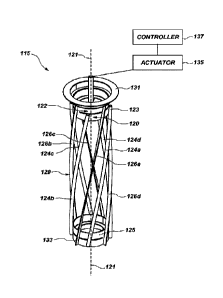
FIG. 2A is a perspective view of a cage assembly 115 according to one or more
embodiments of the present disclosure. FIGS. 2B and 2C are bottom and top
views,
20 respectively, of the cage assembly 115 of FIG. 2A. FIG. 2D is a side
cross-sectional view of
the cage assembly 115 of FIG. 2A. FIG. 2E is an exploded view of the cage
assembly 115 of
FIG. 2A.
Referring to FIGS. 2A-2E together, the cage assembly 115 may include a first
cage 120 and a second cage 122. The first cage 120 and the second cage 122 may
share a
25 center longitudinal axis 121, and one of the first or second cages 120,
122 may be configured
to rotate about the center longitudinal axis relative to the other of the
first or second
cages 120.
=The first cage 120 may include a first upper annular member 123, a first
lower annular
member 125, and a first plurality of helical members 124a, 124b, 124c, 124d
extending
30 between the first upper annular member 123 and the first lower annular
member 125. The
first plurality of helical members may be referred to herein collectively with
the reference
numeral "124". Additionally, one or more of the first plurality of helical
members may
generally be referred to with the reference numeral "124." As used herein, the
term "helical,"
CA 03143544 2022-1-11
- 7 -
when used in reference to members of the first and/or second cages 120, 122,
indicates that
center longitudinal axes of the referenced members have a general shape of at
least a portion
of a helix and/or spiral. In some embodiments, each of the first plurality of
helical
members 124a, 124b, 124c, 124d may have an arcuate radially outermost surface
129
5 intended to contact and rub against an interior surface of an associated
filtration
component 113.
The second cage 122 may include a second upper annular member 131, a second
lower annular member 133, and a second plurality of helical members 126a,
126b, 126c,
126d extending between the second upper annular member 131 and the second
lower annular
10 member 133. The second plurality of helical members may be referred to
herein collectively
with the reference numeral "126". Additionally, one or more of the second
plurality of helical
members may generally be referred to with the reference numeral "126". In some
embodiments, each of the first plurality of helical members 124a, 124b, 124c,
124d may have
a general blade shape for contacting the interior surface of the associated
filtration
15 component 113 (FIG. 1). Each helical member 124 of the first plurality
of helical
members 124a, 124b, 124c, 124d may be disposed between two adjacent helical
members 126 of the second plurality of helical members 126a, 126b, 126c, 126d.
In some embodiments, each helical member 124 may extend helically around an
outer
perimeter of the cage assembly 100 and from the first upper annular member 123
to the first
20 lower annular member 125 such that an upper end of a first helical
member (e.g., helical
member 124a) vertically overlaps with a lower end of an adjacent first member
(e.g., helical
member 124d). In other words, both the upper end of the first helical member
(e.g., helical
member 124b) and the lower end of the adjacent first helical member (e.g.,
helical
member 124d) may intersect a vertical line parallel to the center longitudinal
axis 121 of the
25 cage assembly 115.
In one or more embodiments, each of the first helical members 124 forms an
angle a
with the lower surface of the first upper annular member 123, as well as with
the upper
surface of the first lower annular member 125. In some embodiments, the angle
a may be
within a range of about 1 to about 90 , and more particularly, within a range
of about 20
30 to about 70 (e.g., about 45 ). The angle a may be selected to ensure
that an upper end of a
given first helical member (e.g., helical member 124a) will overlap with a
lower end of an
adjacent first helical member (e.g., helical member 124d).
CA 03143544 2022-1-11
- 8 -
In one or more embodiments, one or more of the first cage 120 and the second
cage 122 may be coupled to an actuator 135 (e.g., a solenoid, motor, an
actuated lever, etc.).
In some embodiments, as is discussed in greater detail below, the actuator 135
may be
configured to rotate the first cage 120 relative to the second cage 122 in a
first direction and
5 a second opposite direction about the center longitudinal axis 121 of the
cage assembly 115.
For instance, the actuator 135 may be operably coupled to a controller 137,
which may
include a user interface, as well as a microprocessor, or any other processing
means capable
of processing software code. The software code may be stored on computer-
readable media
including memory or other data storage that has instructions stored thereon
for controlling
10 the actuator. As is described in greater detail below, in some
embodiments, the actuator 135
may cause the first cage 120 to oscillate between first and second positions
relative to the
second cage 122.
In one or more embodiments, the first cage 120 and the second cage 122 may
both
be disposed within an interior of a respective filtration component 113 (FIG.
1). In some
15 embodiments, the second cage 122 may be fixed relative to the respective
filtration
component 113 (FIG. 1) and may serve to support the respective filtration
component 113
(FIG. 1) and keep the respective filtration component 113 in an open (e.g.,
inflated, non-
collapsed, a set-up) configuration. For instance, the second cage 122 may
serve as an inner
frame of the respective filtration component 113 (FIG. 1).
20 In some embodiments, the first and second cages 120, 122 may include a
metal
material. For instance, the first and second cages 120, 122 may include steel,
stainless steel,
aluminum, titanium, or any metallic alloy. In additional embodiments, the
first and second
cages 120, 122 may include a polymer (e.g., a thermoset). In additional
embodiments, the
first and second cages may include a ceramic coating. In some embodiments, one
or more
25 portions of the first and second cages 120, 122 may be formed via
additive manufacturing.
In some embodiments, a diameter of the cage assembly 100 may be within a range
of about 2.0 inches (5.08 cm) and about 72 inches (182.88 cm). For example, in
some
embodiments, the cage assembly 100 may have a diameter of about 4.0 inches
(10.16 cm).
In operation, the actuator 135 may rotate the first cage 120 about the center
30 longitudinal axis 121 of the cage assembly 115 in a first direction
until each of the first helical
members of the first plurality of helical members 124 abut against or
approximate a second
helical members of the second plurality of helical members 126; subsequently,
the
actuator 135 may rotate the first cage 120 about the center longitudinal axis
121 of the cage
CA 03143544 2022-1-11
- 9 -
assembly 115 in a second opposite direction until each of the first helical
members of the
first plurality of helical members 124 again abut against or approximate a
second helical
member of the second plurality of helical members 126, albeit a different
second helical
member of the second plurality of helical members 126. In other words, the
actuator 135 may
5 cause the first cage 120 to oscillate between first and second positions.
In some
embodiments, the actuator 135 may rotate the first cage 120 about the center
longitudinal
axis 121 of the cage assembly 100 by an angle p. In one or more embodiments,
the angle 13
may be within a range of about 10 and about 450. In additional embodiments,
the angle f3
may be within a range of about 45 and about 90 . In yet further embodiments,
the angle 13
10 may be within a range of about 90 and about 180 .
Rotating the first cage 120 relative to the second cage 122 may cause the
helical
members of the of the first plurality of helical members 124 to rub across
(e.g., scrape
against) the interior surface of the respective filtration component 113, and
rubbing the
helical members of the first plurality of helical members 124 against the
interior surface of
15 the respective filtration component 113 may cause the respective
filtration component 113
to flex and deform (e.g., bulge), which in turn, may cause material 104
accumulated on the
exterior surface of the respective filtration component 113 to be dislodged
and fall off the
respective filtration bag. Thus, rotating the first cage 120 relative to the
second cage 122 may
at least partially clean the respective filtration component 113.
20 In some embodiments, the conveyor system 111 may cause the filtration
component 113 to be relatively tight (e.g., taut) against the second cage 122
during use. For
example, the blower or fan 114 and resulting air flow (and pressure
differential) may suck
the filtration component 113 up against the second cage 122 such that movement
of the first
cage 120 causes the filtration component 113 to deform and flex where the
first helical
25 members 124 rub against the interior surface of the filtration component
113. For instance,
an average outer diameter of the filtration component 113 during operation may
be smaller
than an outer diameter of the first cage 120. The operation of the cage
assembly 115 is
described in greater detail below in regard to FIG. 5.
=The cage assemblies of the present disclosure may be advantageous over
30 conventional systems and methods for cleaning filtration components
(e.g., bags) of
pneumatic conveyance systems. For example, the cage assemblies and methods of
the
present disclosure do not require vibrating or shaking the filtration
components or pneumatic
conveyance systems to remove buildup. As mentioned above, shaking can cause
significant
CA 03143544 2022-1-11
- 10 -
damage to the filtration components and/or pneumatic conveyance systems and
shorten life
cycles of the filtration components and/or pneumatic conveyance systems.
Conversely, the
cage assemblies and methods of the present disclosure do not require shaking
and may lead
to longer life cycles of the filtration components and/or pneumatic conveyance
systems in
5 comparison to conventional systems. Additionally, the cage assemblies and
methods of the
present disclosure do not require that a velocity of a bulk solid being moved
to be reduced to
remove buildup, which is required in reverse flow conventional systems.
Therefore, the cage
assemblies and methods of the present disclosure mitigate a risk and a
likelihood of clogs
occurring within the pneumatic conveyance systems during operation.
Additionally, the cage
10 assemblies and methods of the present disclosure are relatively easy to
manufacture, require
less energy (e.g., electrical energy) than conventional systems (e.g.,
compressed air systems),
and can be retrofitted to current pneumatic conveyance systems. As a result,
the cage
assemblies and methods of the present disclosure may decrease costs of
operation in
comparison to conventional pneumatic conveyance systems and provide a
relatively quick
15 and easy replacement system.
FIG. 3A is a perspective view of a cage assembly 315 according to one or more
embodiments of the present disclosure. FIGS. 313 and 3C are bottom and top
side views,
respectively, of the cage assembly 315 of FIG. 3A. FIG. 3D is a side cross-
sectional view
of the cage assembly 315 of FIG. 3A. FIG. 3E is an exploded view of the cage
assembly 315
20 of FIG. 3A.
Referring to FIGS. 3A-3E together, similar to the cage assembly 115 described
above
in regard to FIGS. 2A-2E, the cage assembly 315 may include a first cage 320
and a second
cage 322. Furthermore, similar to the cage assembly 115 described above in
regard to
FIGS. 2A-2E, the first cage 320 and the second cage 322 may share a center
longitudinal
25 axis 321, and one of the first or second cages 320, 322 may be
configured to rotate about the
center longitudinal axis 321 relative to the other of the first or second
cages 320, 322.
However, instead of helical members 124, 126, the first and second cages 320,
322
may include linear members 324 and adjacent linear members 326, respectively.
The cage
assembly 315 may operate in substantially the same manner as the cage assembly
115
30 described above in regard to FIGS. 2A-2E.
FIG. 4A is a perspective view of a cage assembly 415 according to one or more
embodiments of the present disclosure. FIGS. 411 and 4C are bottom and top
side views,
respectively, of the cage assembly 415 of FIG. 4A. FIG. 4D is a side cross-
sectional view of
CA 03143544 2022-1-11
- 11 -
the cage assembly 415 of FIG. 4A. FIG. 4E is an exploded view of the cage
assembly 415 of
FIG. 4A.
Referring to FIGS. 4A-4E together, similar to the cage assembly 115 described
above
in regard to FIGS. 2A-2E, the cage assembly 415 may include a first cage 420
and a second
5 cage 422. Furthermore, similar to the cage assembly 115 described above
in regard to
FIGS. 2A-2E, the first cage 420 and the second cage 422 may share a center
longitudinal
axis 421.
However, instead of helical members 124, 126, the first and second cages 420,
422
may include first ring members 424 and second ring members 426, respectively.
The cage
assembly 415 may operate in substantially the same manner to the cage assembly
115
described above in regard to FIGS. 2A-2E, but rather than rotating about the
center
longitudinal axis 421, one of the first or second cages 420, 422 may move
axially along the
center longitudinal axis 421 relative to the other of the first or second
cages 420, 422. In
some embodiments, an axial distance between the first and second ring members
424, 426
15 may be within a range of about 1.0 inch (2.54 cm) and about 12 inches
(30.48 cm.). For
example, the distance may be about 8 inches (20.32 cm.)
The cage assemblies described above with regard to FIGS. 3A-4E may provide the
same advantages over conventional systems described above in regard to FIGS.
2A-2E.
FIG. 5 is a schematic top cross-sectional view of a first member 560 of a
given
20 cage 520 of a cage assembly 500 pressing (e.g., rubbing) against a
filtration component 113
(e.g., a filtration bag) and dislodging buildup according to one or more
embodiments of the
present disclosure. FIG. 6 is a flow chart illustrating a method 600 of
dislodging buildup
using a cage assembly according to one or more embodiments of the present
disclosure.
Referring to FIGS. 5 and 6 together, the first member 560 may include any of
the
25 first members described above in regard to first cages 120, 320, 420,
and a second
member 562 of a second cage may include any of the second members described
above in
regard to second cages 122, 322, 422.
In some embodiments, the method may include, in response to an event (e.g., a
user
input, a timing sequence, a sensor reading, etc.), causing the first cage of
the cage assembly
30 to move relative to the second cage within a filtration component 113 of
a pneumatic
conveyance system in a first direction, as shown in act 602 of FIG. 6. For
instance, act 602
of the method 600 may include causing the first cage to move relative to the
second cage in
any of the manners described above in regard to FIGS. 1-4E. For example, the
method 600
CA 03143544 2022-1-11
- 12 -
may include rotating the first cage about a center longitudinal axis of the
cage assembly in
the first direction until each of the first member abuts against or
approximates the second
member 562. In other embodiments, the method 600 may include causing the first
member 560 of the first cage to translate axially along the longitudinal axis
of the cage
5 assembly relative to the second member 562 of the second cage.
The method may further include causing the first cage to move relative to the
second
cage within the filtration component in a second opposite direction, as shown
in act 604 of
FIG. 6. For instance, act 604 of the method 600 may include causing the first
cage to move
relative to the second cage in any of the manners described above in regard to
FIGS. 1-4E.
10 Moving
the first cage relative to the second cage may cause the first cage to rub
across
(e.g., scrape against) the interior surface of the filtration component 113,
and may further
cause the filtration component 113 to flex and deform (e.g., bulge). A
resulting deformity of
the filtration component 113 may translate (e.g., move up or down or
angularly) along the
filtration component 113 in directions parallel or orthogonal to a center
longitudinal axis of
15 the
first cage as the first cage moves (e.g., rotates or translates). The
deformity and the
movement of the deformity may cause material 104 accumulated on the exterior
surface
and/or within a wall of the filtration component 113 to be dislodged and fall
off the filtration
component. Thus, moving the first member 560 relative to the second member 562
may at
least partially clean the respective filtration component 113.
20 FIG. 7
is a schematic view of a pneumatic conveyance system according to one or
more embodiments of the present disclosure. This pneumatic conveyance system
700 may
include, for example, a vacuum system, where suction draws material 704 into
the pneumatic
conveyance system 700 and is dislodged in an analogous manner to that
described in regard
to FIG. 1. Any of the cage systems and methods described above in regard to
FIGS. 2A-6
25 may be
utilized in the pneumatic conveyance system of FIG. 7. However, the filtration
component 713 of the pneumatic conveyance system 700 (e.g., the vacuum) may
include any
conventional filtration component of vacuums (e.g., a cartridge filter).
Referring to FIGS. 1-7 together, in additional embodiments, one or more of the
first
cage (e.g., first cage 120) and the second cage (e.g., second cage 122) may be
disposed on
30 the
exterior of the filtration component. For example, the second cage may be
fixed relative
to the respective filtration component, may be disposed within the respective
filtration
component, and may serve as an inner frame of the respective filtration
component. The first
cage may be disposed on an exterior of the respective filtration component and
may be
CA 03143544 2022-1-11
- 13 -
configured to rotate relative to the second cage in any of the manners
described above. For
instance, the first cage may have an arcuate radially innermost surface for
rubbing against an
exterior surface of the respective filtration component 113.
Referring to FIGS. 1-4E together, in additional embodiments, the first cage
(e.g., first
5 cage 120) may be rotatable by 360 relative to the second cage (e.g.,
second cage 122). For
example, the first cage may only rotate in one direction relative to the
second cage.
Referring still to FIGS. 1-4E together, in some embodiments, the first cage
may
include a first upper annular member, a first lower annular member, and at
least one coil
member extending between the first upper annular member and the first lower
annular
10 member. The coil member may extend in a spring shape around an outer
perimeter of the
cage assembly. In some embodiments, the coil member may have an arcuate
radially
outermost surface for rubbing against an interior surface of an associated
filtration
component. The second cage may include a second upper annular member, a second
lower
annular member, and a plurality of linear members extending between the second
upper
15 annular member and the second lower annular member. For instance, the
second cage may
include a second cage similar to the second cage described above in regard to
FIGS. 3A-3E.
Furthermore, an outermost diameter of the second cage may be smaller than an
innermost
diameter of the first cage (e.g., the second cage may be oriented relative to
the first cage).
The first cage may be coupled to an actuator, and the actuator may be
configured to rotate
20 the first cage relative to the second cage via any of the manners
described above. In some
embodiments, the coil member may have a general blade shape for contacting the
interior
surface of the associated filtration component.
Embodiments of the present disclosure further include:
Embodiment 1. A pneumatic conveyance system, comprising: at least one
filtration
25 component; a cage assembly disposed within the at least one filtration
component and
comprising: an actuator; a first cage; and a second cage, wherein the actuator
is configured
to move the first cage relative to the second cage and cause at least a
portion of the first cage
to rub against an interior surface of the at least one filtration component.
Embodiment 2. The pneumatic conveyance system of embodiment 1, wherein the
30 second cage is fixed relative to the at least one filtration component.
Embodiment 3. The pneumatic conveyance system of any one of embodiments 1 and
2, wherein the first cage comprises: an upper annular member; a lower annular
member; and
CA 03143544 2022-1-11
- 14 -
at least one helical member extending between the upper annular member and the
lower
annular member.
Embodiment 4. The pneumatic conveyance system of embodiment 3, wherein the at
least one helical member is disposed between two adjacent helical members of
the second
5 cage.
Embodiment 5. The pneumatic conveyance system of any one of embodiments 1-4,
wherein the first cage comprises: an upper annular member; a lower annular
member; and at
least one linear member extending between the upper annular member and the
lower annular
member.
10 Embodiment 6. The pneumatic conveyance system of embodiment 5, wherein
the at
least one linear member is disposed between two adjacent linear members of the
second cage.
Embodiment 7. The pneumatic conveyance system of any one of embodiments 1-6,
wherein the first cage comprises: an upper annular member; a lower annular
member; and at
least one ring member disposed axially between the upper annular member and
the lower
15 annular member.
Embodiment 8. The pneumatic conveyance system of any one of embodiments 1-7,
wherein the actuator is configured to cause the first cage to rotate about a
center longitudinal
axis of the cage assembly.
Embodiment 9. The pneumatic conveyance system of embodiment 8, wherein the
20 actuator is configured to cause the first cage to rotate 90 about the
center longitudinal axis
of the cage assembly relative to the second cage in a first direction.
Embodiment 10. The pneumatic conveyance system of any one of embodiments 1-9,
wherein the actuator comprises a motor and a lever coupled to the rotating
cage.
Embodiment 11. The pneumatic conveyance system of any one of embodiments 1-10,
25 wherein a diameter of the first cage is greater than an operating
diameter of the filtration
component.
Embodiment 12. The pneumatic conveyance system of any one of embodiments 1-11,
wherein the first cage comprises: an upper annular member; a lower annular
member; and at
least one coil member extending between the upper annular member and the lower
annular
30 member.
Embodiment 13. The pneumatic conveyance system of any one of embodiments 1-12,
further comprising: a hopper; a receptacle within which the filtration
component and cage
CA 03143544 2022-1-11
- 15 -
assembly are at least partially disposed; and a material conveying conduit
extending from
the hopper to the receptacle.
Embodiment 14. The pneumatic conveyance system of any one of embodiments 1-13,
wherein the filtration component comprises one of a bag or cartridge.
5
Embodiment 15. An assembly, comprising: at least one filtration component; and
a
cage assembly disposed within the at least one filtration component, and
comprising: a first
cage; and a second cage, wherein the first cage is configured to rotate about
a center
longitudinal axis relative to the second cage.
Embodiment 16. The assembly of embodiment 15, wherein the cage assembly
further
10
comprises an actuator configured to move the first cage relative to the second
cage and cause
at least a portion of the first cage to rub against an interior surface of the
at least one filtration
component.
Embodiment 17. The assembly of any one of embodiments 15 and 16, wherein the
second cage is fixed relative to the at least one filtration component.
15
Embodiment 18. The assembly of any one of embodiments 15-17, wherein the first
cage comprises: an upper annular member; a lower annular member; and at least
one helical
member extending between the upper annular member and the lower annular
member.
Embodiment 19. The assembly of embodiment 18, wherein the at least one helical
member is disposed between two adjacent helical members of the second cage.
20
Embodiment 20. A method of dislodging material buildup within a pneumatic
conveyance system, comprising: causing a first cage of a cage assembly to
rotate relative to
a second cage within a filtration component in a first direction about a
center longitudinal
axis; and causing the first cage of the cage of the cage assembly to rotate
relative to the
second cage within the filtration component in a second opposite direction
about the center
25 longitudinal axis.
While certain illustrative embodiments have been described in connection with
the
figures, those of ordinary skill in the art will recognize and appreciate that
the scope of this
disclosure is not limited to those embodiments explicitly shown and described
herein. Rather,
many additions, deletions, and modifications to the embodiments described
herein may be
30 made
to produce embodiments within the scope of this disclosure, such as those
hereinafter
claimed, including legal equivalents. In addition, features from one disclosed
embodiment
may be combined with features of another disclosed embodiment while still
being within the
scope of this disclosure, as contemplated by the inventor.
CA 03143544 2022-1-11