Note: Descriptions are shown in the official language in which they were submitted.
CA 03143592 2021-12-15
WO 2020/257179
PCT/US2020/037905
1
WATER INJECTION INTO A HYDROCARBON
RESERVOIR
FIELD OF THE INVENTION
[0001] This invention relates to the injection of water under pressure into
a
hydrocarbon reservoir to facilitate the recovery of hydrocarbons from the
reservoir.
BACKGROUND OF THE INVENTION
[0002] The oil & gas industry continuously strives to increase the recovery
of
hydrocarbons from underground reservoirs. One widely used technique is called
"waterflooding": the injection of water into the reservoir to increase
pressure and displace
hydrocarbons from within the formation. This is considered "secondary
recovery" and
typically follows "primary recovery" wherein the natural pressure and
conditions result in
hydrocarbon production. The injection of water is associated with an energy
cost;
increasingly producers are seeking to lower the cost of production of
hydrocarbons and
there is an ongoing need to reduce the energy input and therefore the
financial cost of
waterflooding.
[0003] The water used for waterflooding typically comes from either
produced water
(PW), i.e. groundwater simultaneously extracted with the oil, or seawater.
Seawater and
PW can also be mixed and in that case, it is referred to as commingling.
Depending on
the composition of the two streams, commingling can result in undesirable
precipitation
of solids. One example is the formation of highly insoluble barium sulfate: PW
can be
high in barium and when commingled with seawater high in sulfate; the barium
sulfate
solubility limit is exceeded and it precipitates. This precipitation is highly
undesirable as
it can lead to plugging of the reservoir with solids and reduce the
effectiveness of
waterflooding and/or add to the pumping energy needed.
[0004] The water used for waterflooding must also be compatible with the
reservoir's
connate water. If there is an incompatibility, undesirable solids can form due
to chemical
interactions between the PW/seawater and the connate water.
CA 03143592 2021-12-15
WO 2020/257179
PCT/US2020/037905
2
[0005] The effectiveness of waterflooding is directly affected by the
volume of water
used and its chemistry. In general, the more water used, the higher the
secondary oil
recovery. It has been proposed that water of lower salinity is more effective
than
relatively high salinity water for secondary oil recovery (see US patent
7,455,109).
[0006] Some known sources of water for waterflooding include:
a) Produced water (PW);
b) Produced water commingled with desalinated seawater;
c) Produced water commingled with seawater;
d) Seawater;
e) Nanofiltered seawater (filtered to remove divalent ions).
[0007] Each of these options face challenges:
[0008] Regarding (a), produced water typically has a very high salinity
which can
reduce its effectiveness in waterflooding applications. Also, depending on
actual
conditions, there may not be sufficient PW available so a second source of
water may be
needed.
[0009] Regarding (b), addition of desalinated water to produced water is
beneficial in
that the salinity is lowered and volume increased but it is energy-intensive
as desalinated
water is typically produced by reverse osmosis (RO) of seawater. RO may
require the
seawater to be pressurized to 60 bar (900 psi, or 6.2MPa) and product water
recovery
may be limited to 35 to 50%.
[0010] Regarding (c), when seawater and PW are commingled, compatibility
issues
may arise and result in precipitation of inorganics, e.g. barium sulfate.
Also, seawater
contains significant organics that can lead to biogrowth and/or reservoir
souring.
[0011] Regarding (d), although seawater is readily available, there can be
compatibility issues with the connate water that can ultimately lead to
injectivity
challenges. Also, the organics in seawater can lead to biological growth
and/or reservoir
souring as noted under (c).
[0012] Regarding (e), filtering of seawater to remove hardness can improve
water
quality by reducing the likelihood of inorganic precipitation but this adds to
the specific
energy requirements.
CA 03143592 2021-12-15
WO 2020/257179
PCT/US2020/037905
3
[0013] There
is therefore a current need to provide an energy efficient, and therefore
cost efficient, way of pumping water into hydrocarbon reservoirs to stimulate
production,
whilst keeping the salinity of the water as low as possible and if possible
avoid adding the
organics or the inorganic chemicals in seawater which can lead to biological
growth,
reservoir souring or precipitation of insoluble compounds.
[0014]
US9227586 describes diluting a concentrated brine solution with saline water
from waste drilling mud and then use the diluted solution as a frack fluid.
[0015]
US7455109B2 describes a method of applying forward osmosis principles to
prepare desalinated or low salinity water for waterflooding a hydrocarbon
reservoir. The
target total dissolved solids in the water for waterflooding is in the range
of 200 ¨ 5,000
mg/L and most preferably 1,000 to 3,000 mg/L.
[0016] The
journal article by Coday et al, "The Sweet Spot of Forward Osmosis:
Treatment of Produced Water, Drilling Wastewater, and other Complex and
Difficult
Liquid Streams," Desalination 333 (2014) 23-25, describes a number of
different
applications, but the main focus of the article is on two processes: (i)
producing water
through a two-step FO process where the second step involves removing water
from the
draw solution and re-concentrating the draw solution for reuse in the first
step; and (ii)
applying osmotic dilution to extract water from a wastewater to minimize
hauling costs.
BRIEF SUMMARY OF THE DISCLOSURE
[0017] The
invention more particularly includes a method of injecting water into a
hydrocarbon reservoir, comprising: (a) passing a first stream of water having
a first
salinity at a first pressure across a first side of an osmotic membrane; (b)
passing a
second stream of water having a second salinity at a second pressure across a
second side
of the membrane; (c) wherein the first pressure is approximately the same as
or is greater
than the second pressure; (d) wherein the first salinity is greater than the
second salinity;
(e) whereby water is drawn across the membrane from the second stream into the
first
stream by osmotic energy to produce an injection stream of water at
approximately the
first pressure and having a salinity lower than the first salinity; (f)
injecting the injection
stream of water into a hydrocarbon reservoir.
CA 03143592 2021-12-15
WO 2020/257179
PCT/US2020/037905
4
[0018] The term "approximately the same as" in this context means +/-3 bar
(0.3
MPa).
[0019] The first salinity may be at least 80 g/L greater than the second
salinity in
terms of total dissolved solids (such as between 80 g/L and 300 g/L),
optionally at least
120 g/L greater (such as between 120 and 260 g/L. The first pressure may be
between 4
and 60 bar (0.4 and 6 MPa) greater than the second pressure, optionally
between 6 and 40
bar (0.6 and 4 MPa) greater, such as between 10 and 30 bar (1 and 3 MPA)
greater. The
first stream may be produced water, which may have salinity between 120 and
290 g/L
total dissolved solids, optionally between 160 and 280 g/L total dissolved
solids. The
second stream may be seawater or produced water of lower salinity than that of
the first
stream; the seawater may have salinity between 32 g/L total dissolved solids
and 45 g/L
total dissolved solids.
[0020] The first stream may be diluted 20 ¨ 40%, optionally 25 ¨ 30%, with
water
drawn across the membrane in step (e). The second stream may be concentrated
by 30 ¨
70% to between 50 and 70 g/L total dissolved solids.
[0021] The pressure of the injection stream may be increased by passing it
though a
booster pump downstream of the osmotic membrane. This could raise the
injection
pressure to whatever is required for injection. Required injection pressures
can vary 10
to 500 bar (1 to 50 MPa), more commonly 15 to 350 bar (1.5 to 35 MPa), such as
20 to
300 bar (2 to 30 MPa).
[0022] The invention also includes apparatus for injecting water into a
hydrocarbon
reservoir, the apparatus comprising: (a) pressure-retarded osmosis membrane
element(s);
(b) a first pump communicating with the draw side of the pressure retarded
osmosis
membrane element(s) and with a first supply of water at a first salinity; (c)
a second pump
communicating with the feed side of the pressure retarded osmosis membrane
element(s)
and communicating with a second supply of water at a second salinity, lower
than the
first salinity; and (d) the pressure retarded osmosis unit having an output
communicating
with a water injection well of a hydrocarbon reservoir.
[0023] The first pump may be arranged to pump water from the first supply
at a
pressure between 1.5 and 60 bar (0.15 and 6 MPa), optionally between 2 and 40
bar (0.2
CA 03143592 2021-12-15
WO 2020/257179
PCT/US2020/037905
and 4 MPa), such as between 3 and 30 bar (0.3 and 3 MPa). The second pump may
be
arranged to pump water from the second supply at a pressure between 1.5 and 5
bar (0.15
and 0.5 MPa), optionally between 2 and 2.5 bar (0.2 and 0.25 MPa).
[0024] The
apparatus may further comprise a booster pump downstream of the
membrane element(s) and upstream of the water injection well. It may also
comprise a
pretreatment unit or units for treating the first and/or second water supply
upstream of the
membrane element(s). It may also comprise a post-treatment unit or units for
injection of
field chemicals (e.g. biocide, corrosion inhibitors).
[0025]
Examples and various features and advantageous details thereof are explained
more fully with reference to the exemplary, and therefore non-limiting,
examples
illustrated in the accompanying drawings and detailed in the following
description.
Descriptions of known starting materials and processes can be omitted so as
not to
unnecessarily obscure the disclosure in detail. It should be understood,
however, that the
detailed description and the specific examples, while indicating the preferred
examples,
are given by way of illustration only and not by way of limitation. Various
substitutions,
modifications, additions and/or rearrangements within the spirit and/or scope
of the
underlying inventive concept will become apparent to those skilled in the art
from this
disclosure.
[0026] As used
herein, the terms "comprises," "comprising," "includes," "including,"
"has," "having" or any other variation thereof, are intended to cover a non-
exclusive
inclusion. For example, a process, product, article, or apparatus that
comprises a list of
elements is not necessarily limited only those elements but can include other
elements not
expressly listed or inherent to such process, process, article, or apparatus.
Further, unless
expressly stated to the contrary, "or" refers to an inclusive or and not to an
exclusive or.
For example, a condition A or B is satisfied by any one of the following: A is
true (or
present) and B is false (or not present), A is false (or not present) and B is
true (or
present), and both A and B are true (or present).
[0027] The
term substantially, as used herein, is defined to be essentially conforming
to the particular dimension, shape or other word that substantially modifies,
such that the
CA 03143592 2021-12-15
WO 2020/257179
PCT/US2020/037905
6
component need not be exact. For example, substantially cylindrical means that
the object
resembles a cylinder, but can have one or more deviations from a true
cylinder.
[0028] Additionally, any examples or illustrations given herein are not to
be regarded
in any way as restrictions on, limits to, or express definitions of, any term
or terms with
which they are utilized. Instead these examples or illustrations are to be
regarded as being
described with respect to one particular example and as illustrative only.
Those of
ordinary skill in the art will appreciate that any term or terms with which
these examples
or illustrations are utilized encompass other examples as well as
implementations and
adaptations thereof which can or cannot be given therewith or elsewhere in the
specification and all such examples are intended to be included within the
scope of that
term or terms. Language designating such non-limiting examples and
illustrations
includes, but is not limited to: "for example," "for instance," "e.g.," "In
some examples,"
and the like.
[0029] Although the terms first, second, etc. can be used herein to
describe various
elements, components, regions, layers and/or sections, these elements,
components,
regions, layers and/or sections should not be limited by these terms. These
terms are only
used to distinguish one element, component, region, layer or section from
another. Thus,
a first element, component, region, layer or section discussed below could be
termed a
second element, component, region, layer or section without departing from the
teachings
of the present inventive concept.
BRIEF DESCRIPTION OF THE DRAWINGS
[0030] A more complete understanding of the present invention and benefits
thereof
may be acquired by referring to the following description taken in conjunction
with the
accompanying drawings in which:
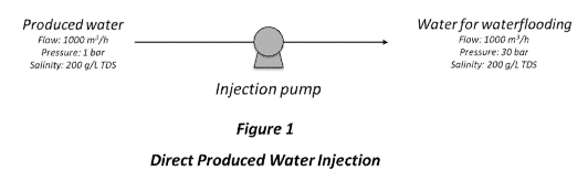
[0031] Figure 1 is a schematic representing the direct injection of
produced water
(prior art);
[0032] Figure 2 is a schematic representing the injection of commingled
produced
water and RO permeate (prior art);
[0033] Figure 3 is a schematic representing the injection of commingled PW
and
seawater (prior art);
CA 03143592 2021-12-15
WO 2020/257179
PCT/US2020/037905
7
[0034] Figure
4 is a schematic representing the direct injection of seawater (prior art);
[0035] Figure
5 is a schematic representing the injection of nanofiltered permeate
from seawater (prior art);
[0036] Figure
6 is a schematic representing the injection of commingled PW and
pressure retarded osmosis (PRO) permeate in accordance with the invention;
[0037] Figure
7 is a schematic representing the injection of commingled PW and
"zero pressure" PRO permeate in accordance with the invention; and
[0038] Figure
8 is a schematic representing the injection of commingled PW and
pressure retarded PRO permeate in accordance with the invention, with a
booster pump
downstream of the PRO unit.
DETAILED DESCRIPTION
[0039] Turning
now to the detailed description of the preferred arrangement or
arrangements of the present invention, it should be understood that the
inventive features
and concepts may be manifested in other arrangements and that the scope of the
invention
is not limited to the embodiments described or illustrated. The scope of the
invention is
intended only to be limited by the scope of the claims that follow.
[0040] This
technique targets secondary oil recovery applications (waterflooding) and
offers a novel process that uses the natural "osmotic energy" of highly saline
produced
water and may provide benefits compared with the prior art techniques.
Possible benefits
may include:
1. Increasing the volume of water available for waterflooding,
2. Improving the quality of the water used for waterflooding by lowering its
salinity and
without introducing compatibility issues associated with commingling with
seawater
3. Simultaneously reducing the specific pumping energy required (i.e. kWh/m3)
[0041] This
technique involves the application of "pressure-retarded osmosis" (PRO)
technology for waterflooding in the oil & gas industry. PRO is a membrane
filtration
process that normally occurs at ambient temperature and uses pumps and
commercially
available PRO membranes. PRO membranes are similar to reverse osmosis
membranes in
CA 03143592 2021-12-15
WO 2020/257179
PCT/US2020/037905
8
that they allow the passage of water but can be highly effective in
restricting the passage
of dissolved ions, including sodium and chloride.
[0042] In PRO, there can be two inlet streams: (i) a high salinity "draw
solution", e.g.
hypersaline produced water at a comparatively higher hydrostatic head, and
(ii) a low
salinity "feed", e.g. seawater, at a comparatively lower hydrostatic head.
Water is drawn
from the low salinity stream through the membrane into the high salinity
stream against
the hydrostatic head. The primary application of PRO referenced in the
literature and
commercial trials relates to installations where fresh water from a river
discharges in the
ocean or other seawater. The salinity gradient between the low salinity river
water and
the higher salinity seawater is used to produce permeate which ultimately
drives a turbine
to produce electricity.
[0043] Water for waterflooding can be injected into a reservoir at a
variety of
pressures. The required injection pressure is not critical to the invention,
which merely
requires two water sources of different salinities such that pressurized
injection of the
higher salinity stream into a well can be augmented at a low energy cost by
employing
the osmotic energy resulting from the difference in salinity of the two
sources. Pressures
for injection can typically vary between 10 bar and 300 bar (1 MPa and 30 MPa)
but can
also be considerably higher.
[0044] In the following embodiments, examples and claims, quoted values for
pressure are absolute values as opposed to gauge values.
[0045] In all the embodiments, a biocide and/or corrosion inhibitors would
be added
to the water for injection, as is standard current procedure. Also a
pretreatment stage
before introduction of fluids to an osmotic membrane unit is normal and the
nature of the
pretreatment will be dictated by the membrane manufacturer. For example,
pretreatment
to remove the suspended solids from seawater and the oil from produced water
would
commonly be required.
[0046] Two possible scenarios (amongst others) for application of this
invention are:
(i) where the draw solution is "hypersaline" produced water and the feed
solution is
seawater and (ii) where the draw solution is seawater and the feed is low
salinity
produced or process water. By "produced water", is meant water which is
extracted
CA 03143592 2021-12-15
WO 2020/257179
PCT/US2020/037905
9
along with hydrocarbons from a hydrocarbon well; it can originate from the
natural
formation (connate water) or be water which has previously been deliberately
injected
(flowback), or a mixture of the two. By "process water" is meant water which
results
from any of a number of treatment processes associated with the production and
processing of hydrocarbons.
[0047] In either scenario, it is proposed that the osmotic energy arising
from the
difference in salinity between the two solutions is employed to assist the
injection pump
or, more accurately, to increase the volume flow rate whilst maintaining
pressure (thus
reducing specific energy), whilst at the same time reducing the salinity of
the water (and
in some cases removing substances which may have an adverse effect on the
formation).
[0048] The first embodiment described below falls under case (i). Figure 6
(which
also relates to Example 6 below) may assist with understanding this
embodiment.
[0049] In a first, hypothetical, embodiment of the invention, it is
envisaged that an oil
producing rig in the North Sea has installed on it a water injection system
comprising a
high pressure produced water injection pump, a low pressure seawater pump and
an
pressure retarded osmosis unit containing one or more membrane elements.
Although
related to one of the examples below, Figure 6 may be helpful in understanding
this
embodiment as well as the second and fourth embodiments below). The elements
consist
of multiple hollow fiber membranes in long cylindrical housings, such as are
commercially available for example from the Toyobo company. Spiral wound PRO
elements with flat sheet membranes are also under development, and this
construction
may be an option for the future.
[0050] There are two inputs to the membrane elements. The one is produced
water at
a hydrostatic head of 30 bar (3 MPa) and a salinity of 200 g/L. This salinity
produces an
osmotic pressure of approximately 170 bar (17 MPa). The second input flow is
seawater
at a hydrostatic head of 3 bar (0.3 MPa) and a salinity of 35 g/L. If
available on the
platform, the seawater could warm seawater that has been used as cooling water
on the
platform. The seawater osmotic pressure is approximately 28 bar (2.8 MPa).
[0051] The two input flows pass across respective sides of the osmotic
membrane,
with the produced water acting as a draw solution drawing pure water across
from the
CA 03143592 2021-12-15
WO 2020/257179
PCT/US2020/037905
seawater feed. The pure water is drawn across the membrane by osmotic action
(i.e.
difference in osmotic pressures), because the 130 bar (13 MPa) difference in
osmotic
pressure exceeds the hydrostatic pressure difference of approximately 30 bar
(3 MPa).
[0052] In fact, as the desalinated water comes through the membrane, the PW
salinity
and osmotic pressure decrease and the salinity and osmotic pressure of the
seawater
increases. Optimum efficiency considerations will result in a design with a 20
¨40%
dilution of the produced water and a seawater salinity increase of 30 ¨ 70%.
This applies
to all the embodiments and examples, and the difference in salinities can
drive the
optimum "recovery". The energy benefit calculations set out below are not
affected by
this, however.
[0053] One output from the membrane element(s) is a flow comprising water
having
a salinity somewhat above that of seawater, which is flowed to sea at low
pressure (1 bar,
0.1 MPa).
[0054] The other output is water to be injected into the reservoir. This
water
injection stream comprises produced water which has been diluted or commingled
with
pure water which has passed through the membrane ¨ this water therefore has a
salinity
which is reduced compared to the produced water. The osmotic energy from the
salinity
difference between the two sides of the membrane is sufficient to cause
permeate flow
across the membrane into the produced water stream at 30 bar (3 MPa), so the
pressure of
the commingled output stream is maintained essentially at that of the produced
water
input stream. Whilst the pressure is kept essentially the same, the volume
flow rate of the
water to be injected is increased vs. that of the produced water. Thereby the
specific
energy consumption (the energy consumed per unit volume of injected water) is
reduced
since the additional volume flow rate of water is provided at essentially the
same
pressure, using osmotic energy. In addition, virtually all contaminants in the
seawater
feed, such as organics and undesirable inorganic ions, are prevented from
passing across
the membrane into the water for injection.
[0055] A second, hypothetical, embodiment is similar in most respects to
the first
embodiment. The only differences are (i) that the pressure at which produced
water is
pumped into the osmotic membrane element is approximately 60 bar (6 MPa) and
the
CA 03143592 2021-12-15
WO 2020/257179
PCT/US2020/037905
11
pressure at which water is injected into the well is approximately the same,
and (ii) that
the osmotic membrane is more robust than the membrane in the first embodiment
and
able to tolerate a larger pressure differential without physically failing.
[0056] The osmotic energy from the difference in salinity between the
seawater and
produced water is still sufficient to overcome the higher static pressure
difference
between the two sides of the membrane. Therefore, all the advantages of the
first
embodiment are provided, with additional energy benefits. The disadvantage is
though
that the lower osmotic energy differential means lower permeate flux and hence
more
membrane area will be required to achieve the same permeate flow. The energy
savings
and hence lower operating expense will be partially offset by the higher
capital expense.
[0057] It should be pointed out that, at the time of filing, no commercial
membrane
for PRO exists which could tolerate a 60 bar (6 MPa) pressure drop. However,
osmotic
membranes are an active area of development and the inventors anticipate that
a
membrane which could tolerate 60 bar (6 MPa) pressure differential, or even
more, may
be available in the near future.
[0058] In a third, hypothetical, embodiment, it is envisaged that a rig in
the North Sea
requires a waterflooding injection pressure of 300 bar (30 MPa). Figure 8 may
be helpful
in understanding this embodiment. The 300 bar (30 MPa) pressure is more than
can be
created by the osmotic energy from the salinity difference between the
produced water
and seawater (using values from the first and second embodiments). This is
addressed by
pumping produced water into the PRO unit at 30 bar (3 MPa) and passing low
pressure (3
bar, 0.3 MPa) seawater into the other side of the PRO unit, as with the first
embodiment.
The concentrated seawater is fed back to the sea at low pressure whilst the 30
bar (3
MPa) injection stream is passed to a booster pump to increase its pressure to
300 bar (30
MPa) for injection. In this embodiment the injection pressure can of course be
as large as
desired, and the energy benefit from increasing the volume of the flow passing
into the
booster pump can be increased as and when it becomes possible for PRO
membranes to
physically support higher pressure differentials.
[0059] In a fourth, hypothetical, embodiment, in mainland USA, a new, deep,
reservoir is to be exploited under an existing older reservoir. The lower
reservoir
CA 03143592 2021-12-15
WO 2020/257179
PCT/US2020/037905
12
produces water at high salinity (280 g/L salinity) whilst the old high-level
reservoir
produces water at a relatively low salinity (50 g/L).
[0060] The upper reservoir is at the stage in its life where waterflooding
is required in
order to increase oil recovery. The upper reservoir therefore has had a water
injection
well drilled and, installed near the injection well, is a water injection
system comprising a
high pressure produced (PW) water injection pump, a low-pressure pump and a
pressure
retarded osmosis (PRO) unit.
[0061] High salinity PW from the deeper reservoir is pumped at 30 bar (3
MPa) into
the PRO unit as a draw solution, whilst low salinity PW from the upper
reservoir is
pumped at 3 bar (0.3 MPa) into the PRO unit as the feed solution. The outputs
from the
PRO are a low-pressure waste stream and a stream comprising the PW from the
deep
well mixed with permeate from the PRO unit at 30 bar (3 MPa).
[0062] The upper reservoir does not produce enough water for waterflooding.
Combining produced water from the lower reservoir with produced water from the
upper
reservoir provides sufficient water, and the additional water is provided at a
very low cost
in terms of energy because the osmotic energy arising from the difference in
salinity is
employed. As with the second and third embodiments, if higher injection
pressure is
required, then this may be provided either (i) by using a PRO unit which can
tolerate a
higher pressure difference (as and when stronger PRO membranes become
available)
and/or (ii) by providing a booster pump downstream of the PRO unit.
[0063] In a fifth embodiment, it is envisaged that a rig in the North Sea
has installed
on it a water injection system in accordance with the invention. The required
injection
water pressure is 300 bar (30 MPa). Two low pressure pumps on the rig convey a
flow of
PW and seawater to respective sides of a pressure retarded osmosis unit at
about 2 bar
(0.2 MPa). The unit is similar to the embodiments above, but there is
essentially no static
pressure drop across the membrane. The outputs from the PRO unit are a low
pressure
concentrated seawater and a low pressure injection water stream comprising
commingled
PW and permeate. A high pressure pump is provided downstream of the PRO unit
to
take the pressure up to 300 bar (30 MPa) for injection into the reservoir.
CA 03143592 2021-12-15
WO 2020/257179
PCT/US2020/037905
13
[0064] The following examples of theoretic models and calculations for both
known
systems and certain embodiments of the invention are given. Each example
relating to
the invention is provided by way of explanation of the invention, one of many
embodiments of the invention, and the following examples should not be read to
limit, or
define, the scope of the invention.
[0065] Examples 1-8, including comparative examples 1-5
Each of these examples is a theoretical calculation of the power requirements
for the
individual pumps and the total power required (see Tables 1 and 2). The power
requirements were calculated based on the following assumptions:
Waterflooding flow required: 1,000 m3/h
Injection pressure needed: Examples 1- 7: 30 bar (3 MPa); Example 8: 60 bar (6
MPa)
PRO pressure: Examples 6 & 8: 30 bar (3 MPa); Example 7: 3 bar (0.3 MPa)
PW salinity: 200 g/L (20%) total dissolved solids (TDS)
Seawater TDS: 35 g/L
Seawater RO operating pressure: 60 bar (6 MPa)
Seawater RO recovery: 33%
Nanofilter operating pressure: 20 bar (2 MPa)
Nanofilter recovery: 67%
Temperature: 25 C
Pump efficiency: 75%
Produced water dilution by PRO permeate: 25%
For Example 8, the energy benefit is not directly comparable since the
required injection
pressure is assumed to be 60 bar (60 MPa).
[0066] The following pumping energy equation was used to derive these
results:
CA 03143592 2021-12-15
WO 2020/257179 PCT/US2020/037905
14
= 31.7.P g (3.6 10.6)' (1)
where
pf,04,.9 = hydraulic power lidite)
q = ficKe capacity
p = den sty of td (A7.073-3,.)
g = wavily (p.81 m/82)
h = differential head (m)
[0067] The electric power required (kW) was calculated by dividing the
hydraulic
power by the assumed combined efficiency for the pump and motor of 75%.
[0068] Comparative Example 1
[0069] Referring to Figure 1, a common approach is simply to inject
produced water
directly. In this example, a high-pressure pump is used to pump high salinity
produced
water (200 g/L TDS) into a reservoir at 30 bar (3 MPa) and a rate of 1000
m3/h.
Calculated parameters are given below in Table 1.
[0070] Comparative Example 2
[0071] Referring to Figure 2, another approach is to dilute the produced
water with
desalinated seawater from a reverse osmosis process. This is done in order to
reduce the
salinity of the PW since reducing salinity is thought to have a favourable
effect on
minimizing connate water compatibility issues and reduce injectivity
challenges. In this
example, PW with a salinity of 200 g/L TDS is fed to a mixing tank using a low
pressure
pump. Seawater is pumped at 60 bar (6 MPa) through a reverse osmosis unit. A
60 bar
(6 MPa) pressure drop is maintained across the RO membrane, which provides a
desalinated pure or low salinity permeate at 1 bar (0.1 MPa) which is also fed
to the
mixing tank. A reject flow of comprises increased salinity seawater at 1 bar
(0.1 MPa).
The mingled water in the tank has a salinity of 150 g/L TDS and this is then
pumped at
30 bar (3 MPa) into the reservoir. Calculated parameters are given below in
Table 1.
Although salinity is reduced and undesirable constituents of the seawater are
eliminated
CA 03143592 2021-12-15
WO 2020/257179
PCT/US2020/037905
by the RO, this process is costly in energy. Because the osmotic unit is a
reverse osmosis
unit, it is possible to achieve a static pressure drop of 60 bar (6 MPa)
across the
membrane using currently available technology.
[0072] Comparative Example 3
[0073] Referring to Figure 3, an alternative method for reducing PW
salinity is
simply to commingle it with seawater. A disadvantage of this approach is that
the
undesirable constituents of seawater are not removed. Of particular concern is
the
formation of barium sulfate. PW can be high in barium and seawater typically
contains
sufficient sulfate that when mixed with PW containing barium, the solubility
limit for
barium sulfate can be exceeded and barium sulfate may precipitate. This can
lead to
plugging of the reservoir and higher pumping pressures being required to
achieve the
desired waterflooding flow. The organics in the seawater can also lead to
undesirable
biological growth in the reservoir, referred to as "reservoir souring". In
this example, a
mixture of seawater and PW having a salinity of 150 g/L TDS is pumped at 30
bar (3
MPa) and a rate of 1000 m3/h into the reservoir. Calculated results are shown
in Table 1.
[0074] Comparative Example 4
[0075] Seawater is often simply injected directly. In situations where
seawater is
plentiful, this is an attractive option which is inexpensive energetically,
but it results in
the injection of considerable amounts of undesirable seawater contaminants
into the
reservoir. The dissolved minerals in seawater can precipitate with minerals in
the
connate water and lead to similar reservoir plugging issues as described in
Example 3.
Also, as noted in Example 3, the organics in the seawater can also lead to
reservoir
souring. In this example, seawater with a salinity of 35 g/L TDS is injected
into the
reservoir at 30 bar (3 MPa) and a rate of 1000 m3/h.
[0076] Comparative Example 5
[0077] Figure 5 relates to this example. To reduce the contaminants in
seawater,
nanofiltration can be used. In this example, seawater is pumped at 20 bar (2
MPa, a
CA 03143592 2021-12-15
WO 2020/257179
PCT/US2020/037905
16
typical value for a nanofiltration unit) and a rate of 1500 m3/h into a
nanofiltration (NF)
unit. A 500 m3/h flow of reject water from the NF unit flows from the unit,
whilst a 1000
m3/h flow at 1 bar (0.1 MPa) flows to a storage tank from where it is pumped
at 30 bar (3
MPa) and a rate of 1000 m3/h into the reservoir. The salinity is changed only
slightly by
the removal of divalent ions by the NF unit. Calculated results are shown in
Table 1.
This approach is comparatively energy intensive.
[0078] Table 1 ¨ Comparative Examples 1-5 (prior art)
Pumping power requirements Water to
waterflooding
Total Flow TDS Energy
Ex Description Pump Flow Head TDS Density Power
Power
(rn3/h) (bar) (g/L) (kW) (kW) (r13/hr)
(g/L) (kWh/m3)
Produced Injection
1 1000 30 200 1.15 1273 1273 1000 200 1.27
water pump
High
Produced pressure RO 750 60 35 1.03 1709
water with pump
2 2939
1000 150 2.94
RO
Injection
permeate 1000 30 150 1.11 1230
pump
PW &
seawater Injection
3 1000 30 150 1.11 1234 1234 1000 150 1.23
commingled pump
(70%/30%)
4 Seawater Injection 1000 30 35 1.03 1140 1140 1000 35 1.14
pump
High
pressure NF 1500 20 35 1.03 1140
NF 2279
pump 1000 35 2.28
permeate
Injection
1000 30 35 1.03 1140
pump
[0079] Example 6
[0080] This
Example (see Figure 6) also assumes the same requirements as the
comparative examples in terms of pressure and flow rate of injected water. A
high
pressure pump conveys PW with a salinity of 200 g/L TDS at 30 bar (3 MPa) and
a flow
rate of 750 m3/h to a pressure retarded osmosis (PRO) unit as the "draw"
stream. Another
low pressure pump conveys seawater (salinity 35 g/1 TDS) at 3 bar (0.3 MPa)
and a flow
rate of 750 m3/h to the PRO unit as the "feed" stream.
CA 03143592 2021-12-15
WO 2020/257179
PCT/US2020/037905
17
[0081] Because the osmotic pressure differential exceeds the hydrostatic
head
differential, pure water is drawn across the PRO membrane against the static
pressure
head from the seawater stream to the PW stream. At the assumed permeate
recovery rate
of 33%, the permeate flow is 250 m3/h. The permeate flow combined with the
original
PW flow is now 1000 m3/h and the pressure remains at 30 bar (3 MPa). Through
the
addition of the permeate, the salinity of the PW has been reduced by 25% from
200 g/L
to 150 g/L TDS. This flow is injected directly into the reservoir. Salinity is
reduced and
seawater contaminants removed, whilst a 1000 m3/h flow rate of injected water
is
achieved for the same energy cost of pumping 750 m3/h at the same pressure.
500 m3/h of
increased salinity seawater flows back to the sea at 1 bar (0.1 MPa).
Calculated results
are shown in Table 2.
[0082] Example 7
[0083] In the event that the required injection pressure is higher than the
limit for
commercially available PRO membranes, or simply because the existing equipment
arrangement favours having the PRO unit upstream, it may be desirable to have
the high-
pressure pump located after the PRO unit. Figure 7 shows an example of this
arrangement. Low pressure pumps convey 750 m3/h of both PW and seawater
streams
each at 3 bar (0.3 MPa) to the PRO unit. Although the term "pressure retarded
osmosis"
is used, in fact there is a negligible pressure increase across the membrane
in this
example and the process is more accurately referred to as "osmotic dilution"
of the
produced water. The 30 bar (3 MPa) injection pressure can be higher or lower
but is used
in this example to provide an effective method for comparing the various
configurations.
Although energy savings are not realized, the key benefits of i) more water
available for
waterflooding, ii) lower salinity and iii) less reservoir incompatibility
issues, are still
realized.
[0084] A 500 m3/h reject stream of increased salinity seawater flows from
the unit.
The other output from the PRO unit is a mixture of a 250 m3/h permeate stream
of
desalinated seawater and the 750 m3/h PW stream. This 1000 m3/h output has
salinity
150 m3/h and flows to a storage tank before being pumped at 30 bar (3 MPa) by
an
CA 03143592 2021-12-15
WO 2020/257179 PCT/US2020/037905
18
injection pump into the reservoir. Calculated results are shown in Table 2.
Although not
as energetically favourable as Example 6, this example compares well
energetically to
other systems which use desalinated seawater.
[0085] Example 8
[0086] In this example (see Figure 8), the required injection pressure is
60 bar (6
MPa). This is higher than the other examples and therefore the energy benefits
cannot be
compared but the example is nonetheless provided for completeness. Using
technology
available today, a PRO membrane cannot tolerate a 60 bar (6 MPa) static
pressure
difference. One way of providing a higher pressure for injection whilst still
obtaining a
benefit from the osmotic energy from the salinity difference is to provide a
downstream
booster pump. A 30 bar (3 MPa) input PW stream to the PRO unit is provided.
The
seawater stream enters the PRO unit at low pressure and the permeate joins the
PW
stream exiting the PRO unit to make a commingled injection stream at 30 bar (3
MPa).
This injection stream is then passed through a booster pump to take the
pressure up to 60
bar (6 MPa).
[0087] Table 2 ¨ Examples 6, 7 and 8
Pumping power requirements
Water to waterflooding
Total
Description Pump Flow Head TDS Density Power Flow TDS Energy
Power
(m3/h) (bar) (g/L) (kW) (m3/h) (m3/hr) (g/L)
(kWh/m3)
Produced Seawater feed
750 2 35 1.03 57
water with pump
6 1012 1000 150 1.01
PRO
Injection pump 750 30 200 1.15 955
permeate
Seawater feed
750 2 35 1.03 57
Produced pump
water with
7 PW feed pump 750 2 200 1.15 64 1350
1000 150 1.35
PRO
permeate
Injection pump 1000 30 150 1.11 1230
Seawater feed
750 2 35 1.03 57
Produced pump
water with
8 PW feed pump 750 30 200 1.15 955 2241
1000 150 2.24
PRO
permeate Downstream
1000 30 150 1.11 1230
booster
CA 03143592 2021-12-15
WO 2020/257179
PCT/US2020/037905
19
[0088] The
advantages of the invention, as exemplified in Example 6, are
summarized below in comparison to the various known methodologies of Examples
1 to
5.
[0089] Example
1: Direct produced water injection: The invention lowers the energy
consumption by 21% and improves the quality of the water sent to waterflooding
by
lowering its salinity by 25%.
[0090] Example
2: PW commingled with RO permeate: The invention lowers energy
consumption by 66% while sending comparable quality water to waterflooding
[0091] Example
3: PW commingled with seawater: The invention lowers energy
consumption by 18% and improves water quality because inorganic and organic
contaminants present in seawater are not added.
[0092] Example
4: Direct seawater injection: The invention lowers energy
consumption by 11% and although the salinity is higher, it improves water
quality
because inorganic and organic contaminants present in seawater are not
injected into the
reservoir.
[0093] Example
5: Nanofiltered (softened) seawater: The invention lowers energy
consumption by 56% and although the salinity is higher, compatibility issues
with
formation are not expected since the water was obtained from the formation.
[0094] In
closing, it should be noted that the discussion of any reference is not an
admission that it is prior art to the present invention, especially any
reference that may
have a publication date after the priority date of this application. At the
same time, each
and every claim below is hereby incorporated into this detailed description or
specification as additional embodiments of the present invention.
[0095]
Although the systems and processes described herein have been described in
detail, it should be understood that various changes, substitutions, and
alterations can be
made without departing from the spirit and scope of the invention as defined
by the
following claims. Those skilled in the art may be able to study the preferred
embodiments and identify other ways to practice the invention that are not
exactly as
described herein. It is the intent of the inventors that variations and
equivalents of the
invention are within the scope of the claims while the description, abstract
and drawings
CA 03143592 2021-12-15
WO 2020/257179
PCT/US2020/037905
are not to be used to limit the scope of the invention. The invention is
specifically
intended to be as broad as the claims below and their equivalents.
REFERENCES
All of the references cited herein are expressly incorporated by reference.
The discussion of
any reference is not an admission that it is prior art to the present
invention, especially any
reference that may have a publication data after the priority date of this
application.
Incorporated references are listed again here for convenience:
US9227856
U S7455109B 2
Coday et al, "The Sweet Spot of Forward Osmosis: Treatment of Produced Water,
Drilling Wastewater, and
other Complex and Difficult Liquid Streams," Desalination 333 (2014) 23-25