Note: Descriptions are shown in the official language in which they were submitted.
CA 03143765 2021-12-16
WO 2020/252593 PCT/CA2020/050859
INDUSTRIAL-SCALE PROCESSING OF CANNABIS MATERIAL
CROSS-REFERENCE TO RELATED APPLICATION
[0001] This application is related to, and claims priority to, United
States
Provisional Patent Application No. 62/864,594, entitled "INDUSTRIAL-SCALE
PROCESSING OF CANNABIS MATERIAL", and filed on June 21, 2019, the entire
contents of which are incorporated by reference herein.
FIELD
[0002] This disclosure relates generally to processing of cannabis
material. In
particular, the disclosure relates to systems and methods for processing
cannabis
material on an industrial scale, in continuous and/or integrated processes or
systems in
some embodiments.
BACKGROUND
[0003] Cannabis materials, such as cannabis plant material and other
materials
that are derived from cannabis plant material, are typically processed in a
segmented
and non-continuous "batch" process in which the cannabis materials are moved
from
one finite processing station to another in batches. As each station completes
its
processing of a batch of input material, personnel move a batch of processed
material
to a next station. This requires allocating personnel not only to operate each
station,
but also to transfer materials from one station to the next.
[0004] Also, due to stringent regulatory requirements such as those in
respect of
weight and loss traceability, a batch process incurs greater cost for
operation. It is
estimated that 50-60% of employee time is spent on administrative
documentation of
tracking cannabis material.
SUMMARY
[0005] Conventional batch processing tends to be slow and inefficient in
that
each station completes its processing of a batch of input material before any
processed
CA 03143765 2021-12-16
WO 2020/252593 PCT/CA2020/050859
material is provided to a next station so that the next station can begin its
processing.
This can introduce time delay and/or inefficiencies in usage of processing
stations if, for
example, a processing station is idle during a time when it has no input
material to
process because a previous processing station from which it receives input
material has
not yet completed processing of a batch of cannabis material.
[0006] Human intervention required in conventional batch processing is
also
prone to increased operation cost, contamination risk, and human error as a
result of
the high level of involvement of personnel in such processing.
[0007] Some embodiments disclosed herein propose establishing fluid
communication and/or other transfer means or mechanisms between cannabis
material
processing stations so that materials flow through a processing system without
the need
for human intervention to physically move those materials during processing.
[0008] Some embodiments propose also or instead integrating cannabis
material
processing stations that are separate stations in conventional processing
systems.
[0009] At least some aspects of processing are automated in some
embodiments. For example, electronic equipment and/or components that execute
software are used in some embodiments for such purposes as coordinating or
synchronizing processing by stations and/or operation of transfer mechanisms
such as
fluid pumps to streamline and potentially optimize processing.
[0010] Regarding employee time spent on administrative documentation for
tracking cannabis material as noted above, it is expected that a continuous
and/or
otherwise integrated, automated, or streamlined process or system would
significantly
reduce the amount of this administrative work, by half or more.
[0011] One particular aspect of the present disclosure relates to a
system
comprising: a first station to reduce size of a cannabis plant material; and a
second
station, coupled to receive reduced size cannabis plant material from the
first station, to
obtain from the reduced size cannabis plant material a cannabis extract
including at
2
CA 03143765 2021-12-16
WO 2020/252593 PCT/CA2020/050859
least one cannabinoid and/or terpene. The second station may be coupled to
receive a
continuous supply of reduced size cannabis plant material, for example.
[0012] In some embodiments, the second station is in fluid communication
with
the first station.
[0013] In some embodiments, the second station is coupled to the first
station via
a transfer mechanism configured for transferring the reduced size cannabis
plant
material from the first station to the second station.
[0014] In some embodiments, the transfer mechanism comprises a vessel to
hold
the reduced size cannabis plant material from the first station before
transfer to the
second station.
[0015] In some embodiments, the transfer mechanism comprises a conveyor.
[0016] In some embodiments, the transfer mechanism comprises a pipe.
[0017] In some embodiments, the second station is configured to obtain
the
cannabis extract by performing mechanical extraction on the reduced size
cannabis
plant material.
[0018] In some embodiments, the second station is configured to obtain
the
cannabis extract by extracting the reduced size cannabis plant material with
an
extraction solvent.
[0019] In some embodiments, the second station is configured for
contacting the
reduced size cannabis plant material with the extraction solvent.
[0020] In some embodiments, the first station is configured for
contacting the
cannabis plant material with the extraction solvent.
[0021] In some embodiments, the extraction solvent transfers the reduced
size
cannabis plant material from the first station to the second station.
3
CA 03143765 2021-12-16
WO 2020/252593 PCT/CA2020/050859
[0022] In some embodiments, the extracting comprises a warm solvent
extraction
process that further causes decarboxylation of the at least one cannabinoid.
[0023] In some embodiments, the system further comprises a winterization
station, coupled to receive the cannabis extract from the second station, to
winterize the
cannabis extract. The winterization station may be coupled to receive a
continuous
supply of the cannabis extract from the second station.
[0024] In some embodiments, the winterization station is in fluid
communication
with the second station.
[0025] In some embodiments, the winterization station is coupled to the
second
station via a transfer mechanism configured for transferring the cannabis
extract from
the second station to the winterization station.
[0026] In some embodiments, the transfer mechanism configured for
transferring
the cannabis extract from the second station to the winterization station
comprises a
pipe.
[0027] In some embodiments, the transfer mechanism configured for
transferring
the cannabis extract from the second station to the winterization station
comprises a
vessel to hold the cannabis extract from the second station before transfer to
the
winterization station.
[0028] In some embodiments, the system further comprises: a winterization
station, coupled to receive the cannabis extract from the second station, to
winterize the
cannabis extract, and the extraction solvent transfers the cannabis extract
from the
second station to the winterization station. The winterization station may be
coupled to
receive a continuous supply of the cannabis extract from the second station.
[0029] In some embodiments, the winterization station is configured for
contacting
the cannabis extract with a winterization solvent.
[0030] In some embodiments, the system further comprises a distillation
station,
coupled to receive winterized cannabis extract from the winterization station,
to purify
4
CA 03143765 2021-12-16
WO 2020/252593 PCT/CA2020/050859
the at least one cannabinoid and/or terpene. The distillation station may be
coupled to
receive a continuous supply of the winterized cannabis extract from the
winterization
station.
[0031] In some embodiments, the distillation station is in fluid
communication with
the winterization station.
[0032] In some embodiments, the distillation station is coupled to the
winterization
station via a transfer mechanism configured for transferring the winterized
cannabis
extract from the winterization station to the distillation station.
[0033] In some embodiments, the transfer mechanism configured for
transferring
the winterized cannabis extract from the winterization station to the
distillation station
comprises a pipe.
[0034] In some embodiments, the transfer mechanism is configured for
transferring the winterized cannabis extract from the winterization station to
the
distillation station comprises a vessel to hold the winterized cannabis
extract from the
winterization station before transfer to the distillation station.
[0035] In some embodiments, the system further comprises a distillation
station,
coupled to receive winterized cannabis extract from the winterization station,
to purify
the at least one cannabinoid and/or terpene, and the winterization solvent
transfers the
winterized cannabis extract from the winterization station to the distillation
station. The
distillation station may be coupled to receive a continuous supply of the
winterized
cannabis extract from the winterization station.
[0036] In some embodiments, the system further comprises a distillation
station,
coupled to receive the cannabis extract from the second station, to purify the
at least
one cannabinoid and/or terpene. The distillation station may be coupled to
receive a
continuous supply of the cannabis extract from the second station.
[0037] In some embodiments, the distillation station is in fluid
communication with
the second station.
CA 03143765 2021-12-16
WO 2020/252593 PCT/CA2020/050859
[0038] In some embodiments, the distillation station is coupled to the
second
station via a transfer mechanism configured for transferring the cannabis
extract from
the second station to the distillation station.
[0039] In some embodiments, the transfer mechanism is configured for
transferring the cannabis extract from the second station to the distillation
station
comprises a pipe.
[0040] In some embodiments, the transfer mechanism configured for
transferring
the cannabis extract from the second station to the distillation station
comprises a
vessel to hold the cannabis extract from the second station before transfer to
the
distillation station.
[0041] In some embodiments, the system further comprises a distillation
station,
coupled to receive the cannabis extract from the second station, to purify the
at least
one cannabinoid and/or terpene, and the extraction solvent transfers the
cannabis
extract from the second station to the distillation station. The distillation
station may be
coupled to receive a continuous supply of the cannabis extract from the second
station.
[0042] In some embodiments, the system further comprises a separation
station,
coupled to receive the cannabis extract from the second station, to separate
the at least
one cannabinoid and/or terpene from the cannabis extract.
[0043] In some embodiments, the system further comprises a separation
station,
coupled to receive winterized cannabis extract from the winterization station,
to
separate the at least one cannabinoid and/or terpene from the winterized
cannabis
extract.
[0044] In some embodiments, the system further comprises a separation
station,
coupled to receive a distillate from the distillation station, to further
purify the at least
one cannabinoid and/or terpene.
[0045] In some embodiments, the system further comprises a pre-treatment
station to pre-treat the cannabis plant material, and the first station is
coupled to receive
6
CA 03143765 2021-12-16
WO 2020/252593 PCT/CA2020/050859
pre-treated cannabis plant material from the pre-treatment station and reduce
size of
the pre-treated cannabis plant material.
[0046] Another aspect of the present disclosure relates to a method
comprising:
processing a cannabis plant material at a first station, to reduce size of the
cannabis
plant material and produce reduced size cannabis plant material; and
processing the
reduced size cannabis plant material, at a second station that is coupled to
receive the
reduced size cannabis plant material from the first station, to obtain from
the reduced
size cannabis plant material a cannabis extract including at least one
cannabinoid
and/or terpene. The second station may be coupled to receive a continuous
supply of
reduced size cannabis plant material, for example.
[0047] In some embodiments, the second station is in fluid communication
with
the first station.
[0048] In some embodiments, the method further comprises controlling a
transfer
mechanism to transfer the reduced size cannabis plant material from the first
station to
the second station.
[0049] In some embodiments, processing the reduced size cannabis plant
material at the second station comprises performing mechanical extraction on
the
reduced size cannabis plant material.
[0050] In some embodiments, processing the reduced size cannabis plant
material at the second station comprises extracting the reduced size cannabis
plant
material with an extraction solvent.
[0051] In some embodiments, the extracting comprises contacting the
reduced
size cannabis plant material with the extraction solvent.
[0052] In some embodiments, processing the cannabis plant material at the
first
station comprises contacting the cannabis plant material with the extraction
solvent to
transfer the reduced size cannabis plant material from the first station to
the second
station.
7
CA 03143765 2021-12-16
WO 2020/252593 PCT/CA2020/050859
[0053] In some embodiments, the extracting comprises a warm solvent
extraction
process that further causes decarboxylation of the at least one cannabinoid.
[0054] In some embodiments, the method further comprises processing the
cannabis extract, at a winterization station that is coupled to receive the
cannabis
extract from the second station, to winterize the cannabis extract. The
winterization
station may be coupled to receive a continuous supply of the cannabis extract,
for
example.
[0055] In some embodiments, the winterization station is in fluid
communication
with the second station.
[0056] In some embodiments, the method further comprises controlling a
transfer
mechanism to transfer the cannabis extract from the second station to the
winterization
station.
[0057] In some embodiments, the method further comprises: transferring
the
cannabis extract, in a continuous supply for example, from the second station
to a
winterization station using the extraction solvent; and processing the
cannabis extract,
at the winterization station, to winterize the cannabis extract.
[0058] In some embodiments, processing the cannabis extract at the
winterization
station comprises contacting the cannabis extract with a winterization
solvent.
[0059] In some embodiments, the method further comprises processing
winterized cannabis extract, at a distillation station that is coupled to
receive winterized
cannabis extract from the winterization station, to purify the at least one
cannabinoid
and/or terpene. The distillation station may be coupled to receive a
continuous supply
of the winterized cannabis extract from the winterization station, for
example.
[0060] In some embodiments, the distillation station is in fluid
communication with
the winterization station.
8
CA 03143765 2021-12-16
WO 2020/252593 PCT/CA2020/050859
[0061] In some embodiments, the method further comprises controlling a
transfer
mechanism to transfer the winterized cannabis extract from the winterization
station to
the distillation station.
[0062] In some embodiments, the method further comprises: transferring
winterized cannabis extract, in a continuous supply for example, from the
winterization
station to a distillation station using the winterization solvent; and
processing the
winterized cannabis extract, at the distillation station, to purify the at
least one
cannabinoid and/or terpene.
[0063] In some embodiments, the method further comprises processing the
cannabis extract, at a distillation station that is coupled to receive the
cannabis extract
from the second station, to purify the at least one cannabinoid and/or
terpene. The
distillation station may be coupled to receive a continuous supply of the
cannabis
extract from the second station, for example.
[0064] In some embodiments, the distillation station is in fluid
communication with
the second station.
[0065] In some embodiments, the method further comprises controlling a
transfer
mechanism to transfer the cannabis extract from the second station to the
distillation
station.
[0066] In some embodiments, the method further comprises: transferring
the
cannabis extract, in a continuous supply for example, from the second station
to a
distillation station using the extraction solvent; and processing the cannabis
extract, at
the distillation station, to purify the at least one cannabinoid and/or
terpene.
[0067] In some embodiments, the method further comprises processing the
cannabis extract, at a separation station that is coupled to receive the
cannabis extract
from the second station, to separate the at least one cannabinoid and/or
terpene from
the cannabis extract.
9
CA 03143765 2021-12-16
WO 2020/252593 PCT/CA2020/050859
[0068] In some embodiments, the method further comprises processing
winterized cannabis extract, at a separation station that is coupled to
receive the
winterized cannabis extract from the winterization station, to separate the at
least one
cannabinoid and/or terpene from the winterized cannabis extract.
[0069] In some embodiments, the method further comprises processing a
distillate, at a separation station that is coupled to receive the distillate
from the
distillation station, to further purify the at least one cannabinoid and/or
terpene.
[0070] In some embodiments, the method further comprises pre-treating the
cannabis plant material at pre-treatment station, and the processing at the
first station
comprises processing pre-treated cannabis plant material from the pre-
treatment
station.
[0071] A system according to a further aspect of the present disclosure
includes
one or more controllers to control operation of a first station to reduce size
of a cannabis
plant material, and to control operation of a second station that is coupled
to receive a
continuous supply of reduced size cannabis plant material from the first
station and to
obtain from the reduced size cannabis plant material a cannabis extract
including at
least one cannabinoid and/or terpene.
[0072] The one or more controllers may be configured to coordinate
operation of
the first station and operation of the second station with the continuous
supply.
[0073] The one or more controllers may include a controller to
coordinate, with
operation of the first station and operation of the second station, operation
of a transfer
mechanism to transfer the reduced size cannabis plant material from the first
station to
the second station.
[0074] The one or more controllers may include a controller to coordinate
operation of one or more further stations with each other and/or with
operation of either
or both of the first station and the second station.
CA 03143765 2021-12-16
WO 2020/252593 PCT/CA2020/050859
[0075] In an embodiment, the one or more controllers include a controller
to
coordinate operation of one or more transfer mechanisms to transfer cannabis
material
to or from the one or more further stations with operation of the one or more
further
stations and/or with operation of either or both of the first station and the
second station.
[0076] The one or more further stations may include any one or more of: a
decarboxylation station; a winterization station; a distillation station; a
separation station;
and a pre-treatment station, for example.
[0077] A method according to yet another aspect of the present disclosure
involves controlling processing of a cannabis plant material at a first
station to reduce
size of the cannabis plant material and produce reduced size cannabis plant
material;
and controlling processing of the reduced size cannabis plant material at a
second
station that is coupled to receive a continuous supply of the reduced size
cannabis plant
material from the first station and to obtain from the reduced size cannabis
plant
material a cannabis extract including at least one cannabinoid and/or terpene.
[0078] Controlling processing at the first station and controlling
processing at the
second station may involve coordinating the processing at the first station
and the
processing at the second station with the continuous supply.
[0079] Such a method may involve controlling transfer of the reduced size
cannabis plant material from the first station to the second station.
[0080] In some embodiments, a method involves coordinating processing at
one
or more further stations with each other and/or with the processing at either
or both of
the first station and the second station.
[0081] Some embodiments may involve coordinating transfer of cannabis
material
to or from the one or more further stations with the processing at the one or
more further
stations and/or with the processing at either or both of the first station and
the second
station. As noted above, the one or more further stations may include any one
or more
of: a decarboxylation station; a winterization station; a distillation
station; a separation
station; and a pre-treatment station, for example.
11
CA 03143765 2021-12-16
WO 2020/252593 PCT/CA2020/050859
[0082] Another aspect of the present disclosure relates to a system
comprising: a
first station to process a cannabis plant material to obtain a cannabis
extract including at
least one cannabinoid and/or terpene; and a second station, coupled to receive
the
cannabis extract from the first station, to purify the cannabis extract. The
cannabis
extract is continuously transferred from the first station in some
embodiments.
[0083] The system may also include a transfer mechanism, coupled to the
first
station and to the second station, to continuously transfer at least a portion
of the
cannabis extract from the first station to the second station.
[0084] The first station may be configured to obtain the cannabis extract
by
processing the cannabis plant material with an extraction solvent, and the
transfer
mechanism may be configured to transfer at least the portion of the cannabis
extract to
the second station in at least a portion of the extraction solvent.
[0085] The first station may be configured to obtain the cannabis extract
by
performing mechanical extraction on the cannabis plant material.
[0086] In some embodiments, the first station comprises: a first
substation to
reduce size of the cannabis plant material; and a second substation, coupled
to receive
reduced size cannabis plant material from the first substation, to obtain the
cannabis
extract from the reduced size cannabis plant material.
[0087] In some embodiments, the first station comprises: a pre-treatment
substation to pre-treat cannabis plant material; and an extraction substation,
coupled to
receive pre-treated cannabis plant material from the pre-treatment substation,
to obtain
the cannabis extract from the pre-treated cannabis plant material.
[0088] In some embodiments, the first station comprises: a pre-treatment
substation to pre-treat cannabis plant material; a first substation, coupled
to receive pre-
treated cannabis plant material from the pre-treatment substation, to reduce
size of the
pre-treated cannabis plant material; and a second substation, coupled to
receive
reduced size cannabis plant material from the first substation, to obtain the
cannabis
extract from the reduced size cannabis plant material.
12
CA 03143765 2021-12-16
WO 2020/252593 PCT/CA2020/050859
[0089] In some embodiments, the second station comprises a winterization
substation to process the cannabis extract and obtain a winterized extract.
[0090] The winterization substation may be configured to winterize the
cannabis
extract in presence of a winterization solvent to obtain the winterized
extract.
[0091] In some embodiments, the second station comprises a distillation
substation to process the cannabis extract and obtain the at least one
cannabinoid
and/or terpene.
[0092] In some embodiments, the second station further comprises a
distillation
substation, coupled to receive the winterized extract from the winterization
substation, to
process the winterized extract and obtain the at least one cannabinoid and/or
terpene.
[0093] A system may include a transfer mechanism, coupled to the
winterization
substation and to the distillation substation, to transfer the winterized
extract to the
distillation substation.
[0094] In some embodiments, the second station comprises a separation
substation to process the cannabis extract and obtain the at least one
cannabinoid
and/or terpene.
[0095] In some embodiments, the second station further comprises a
separation
substation, coupled to receive the winterized extract from the winterization
substation, to
process the winterized extract and obtain the at least one cannabinoid and/or
terpene.
[0096] A system may include a transfer mechanism, coupled to the
winterization
substation and to the separation substation, to transfer the winterized
extract to the
separation substation.
[0097] In some embodiments, the second station further comprises a
separation
substation, coupled to receive from the distillation substation a distillate
comprising the
at least one cannabinoid and/or terpene, to process the distillate and further
purify the at
least one cannabinoid and/or terpene.
13
CA 03143765 2021-12-16
WO 2020/252593 PCT/CA2020/050859
[0098] A system may include a transfer mechanism, coupled to the
separation
substation and to the distillation substation, to transfer the distillate to
the separation
substation.
[0099] In some embodiments, the first station includes an extraction
vessel to
hold the cannabis extract in an extraction solvent; and a transfer mechanism
coupled to
the extraction vessel and configured to continuously withdraw a portion of the
extraction
solvent containing the cannabis extract from the extraction vessel so as to
substantially
maintain at least a minimum volume of plant material and extraction solvent in
the
extraction vessel. The transfer mechanism may be configured to continuously
withdraw
the portion of the extraction solvent containing the cannabis extract from the
extraction
vessel so as to substantially maintain a constant volume of plant material and
extraction
solvent in the extraction vessel.
[0100] The second station may include a winterization substation coupled
to the
transfer mechanism, to receive the withdrawn portion of the extraction solvent
containing the cannabis extract.
[0101] The winterization substation may be configured to contact the
extract with
a winterization solvent.
[0102] In some embodiments, a distillation substation is coupled to the
transfer
mechanism, to receive the withdrawn portion of the extraction solvent
containing the
cannabis extract. The second station may include a separation substation in
fluid
communication with the distillation substation. A transfer mechanism may be
coupled to
the separation substation and to the distillation substation, to transfer a
distillate from
the distillation substation to the separation substation.
[0103] A separation substation may be coupled to the transfer mechanism,
to
receive the withdrawn portion of the extraction solvent containing the
cannabis extract.
[0104] The second station may include a distillation substation in fluid
communication with the winterization substation. A transfer mechanism may be
14
CA 03143765 2021-12-16
WO 2020/252593 PCT/CA2020/050859
coupled to the winterization substation and to the distillation substation, to
transfer
winterized extract to the distillation station.
[0105] In some embodiments, a separation substation is in fluid
communication
with the winterization substation. A transfer mechanism may be coupled to the
winterization substation and to the separation station, to transfer winterized
extract to
the separation station.
[0106] Another aspect of the present disclosure relates to a method
comprising:
processing a cannabis plant material at a first station to obtain a cannabis
extract
including at least one cannabinoid and/or terpene; and processing the cannabis
extract,
at a second station that is coupled to receive the cannabis extract from the
first station,
to purify the cannabis extract. The second station may be coupled to receive
the
cannabis extract that is continuously transferred from the first station, for
example.
[0107] A method may include continuously transferring at least a portion
of the
cannabis extract from the first station to the second station.
[0108] The processing at the first station may involve processing the
cannabis
plant material with an extraction solvent, and continuously transferring may
involve
transferring at least the portion of the cannabis extract to the second
station in at least a
portion of the extraction solvent.
[0109] In an embodiment, the processing at the first station involves
performing
mechanical extraction on the cannabis plant material.
[0110] In some embodiments, the processing at the first station
comprises:
processing the cannabis plant material at a first substation of the first
station to reduce
size of the cannabis plant material; and processing reduced size cannabis
plant material
from the first substation, at a second substation of the first station that is
coupled to
receive the reduced size cannabis plant material from the first substation, to
obtain the
cannabis extract from the reduced size cannabis plant material.
CA 03143765 2021-12-16
WO 2020/252593 PCT/CA2020/050859
[0111] In some embodiments, the processing at the first station
comprises: pre-
treating cannabis plant material at a pre-treatment substation; and processing
pre-
treated cannabis plant material from the pre-treatment substation, at an
extraction
substation of the first station that is coupled to receive the pre-treated
cannabis plant
material from the pre-treatment substation, to obtain the cannabis extract
from the pre-
treated cannabis plant material.
[0112] In some embodiments, the processing at the first station
comprises: pre-
treating cannabis plant material at a pre-treatment substation; processing pre-
treated
cannabis plant material at a first substation that is coupled to receive the
pre-treated
cannabis plant material from the pre-treatment substation, to reduce size of
the pre-
treated cannabis plant material; and processing reduced size cannabis plant
material
from the first substation, at a second substation of the first station that is
coupled to
receive the reduced size cannabis plant material from the first substation, to
obtain the
cannabis extract from the reduced size cannabis plant material.
[0113] In some embodiments, the processing at the second station
comprises
winterizing the cannabis extract to obtain a winterized extract. The
winterizing may
involve winterizing the cannabis extract in presence of a winterization
solvent to obtain
the winterized extract.
[0114] In some embodiments, processing at the second station comprises
distilling the cannabis extract to obtain the at least one cannabinoid and/or
terpene.
[0115] In some embodiments, processing at the second station further
comprises
distilling the winterized extract to obtain the at least one cannabinoid
and/or terpene.
[0116] In some embodiments, the processing at the second station
comprises
performing separation to separate the at least one cannabinoid and/or terpene
in the
cannabis extract and obtain the at least one cannabinoid and/or terpene.
[0117] In some embodiments, the processing at the second station further
comprises performing separation to separate the at least one cannabinoid
and/or
terpene in the winterized extract and obtain the at least one cannabinoid
and/or terpene.
16
CA 03143765 2021-12-16
WO 2020/252593 PCT/CA2020/050859
[0118] In some embodiments, the processing at the second station further
comprises performing separation to further purify the at least one cannabinoid
and/or
terpene by separating the at least one cannabinoid and/or terpene in a
distillate
comprising the at least one cannabinoid and/or terpene.
[0119] The first station may include an extraction vessel to hold the
cannabis
extract in an extraction solvent, and a method may involve continuously
withdrawing a
portion of the extraction solvent containing the cannabis extract from the
extraction
vessel so as to substantially maintain at least a minimum volume of plant
material and
extraction solvent in the extraction vessel. Continuously withdrawing may
involve
continuously withdrawing the portion of the extraction solvent containing the
cannabis
extract from the extraction vessel so as to substantially maintain a constant
volume of
plant material and extraction solvent in the extraction vessel.
[0120] The second station may include a winterization substation in fluid
communication with the extraction vessel, and a method may involve
transferring the
extract from the extraction vessel to the winterization substation.
[0121] The withdrawn portion of the extraction solvent may transfer the
extract
from the extraction vessel to the winterization substation.
[0122] A method may involve incorporating a winterization solvent such
that the
extract is in contact with the winterization solvent in the winterization
substation.
[0123] In some embodiments, a method involves winterizing the extract.
[0124] The second station further comprises a distillation substation in
fluid
communication with the winterization substation. A method may involve
transferring
winterized extract from the winterization substation to the distillation
substation. In
some embodiments, a method involves distillation of the winterized extract to
purify the
at least one cannabinoid and/or terpene.
[0125] In an embodiment, the second station includes a distillation
substation in
fluid communication with the extraction vessel. The withdrawn portion of the
extraction
17
CA 03143765 2021-12-16
WO 2020/252593 PCT/CA2020/050859
solvent may transfer the extract from the extraction vessel to the
distillation substation.
In some embodiments, a method involves distillation of the extract to purify
the at least
one cannabinoid and/or terpene.
[0126] A method may involve separation of the at least one cannabinoid
and/or
terpene in the cannabis plant extract to obtain the at least one cannabinoid
and/or
terpene.
[0127] In an embodiment, a method involves separation of the at least one
cannabinoid and/or terpene in winterized extract from the winterization
substation.
[0128] A method may involve separation of a distillate comprising the at
least one
cannabinoid and/or terpene, to further purify the at least one cannabinoid
and/or
terpene.
[0129] Another aspect of the present disclosure relates to a method
comprising:
processing a cannabis plant material at an extraction station to obtain a
cannabis
extract including at least one cannabinoid and/or terpene; and continuously
transferring
at least a portion of the cannabis extract to a purification station that is
coupled to
receive the cannabis extract from the extraction station.
[0130] In some embodiments, the processing at an extraction station
comprises
processing the cannabis plant material with an extraction solvent, and wherein
the
transferring comprises transferring at least the portion of the cannabis
extract in at least
a portion of the extraction solvent.
[0131] In some embodiments, the processing at an extraction station
comprises
performing mechanical extraction on the cannabis plant material.
[0132] In some embodiments, the purification station comprises a
winterization
station, and the method further comprises winterizing the cannabis extract in
presence
of a winterization solvent to obtain a winterized extract.
18
CA 03143765 2021-12-16
WO 2020/252593 PCT/CA2020/050859
[0133] In some embodiments, the purification station further comprises a
distillation station, and the method further comprises distillation of the
winterized extract
to obtain the at least one cannabinoid and/or terpene.
[0134] In some embodiments, the purification station comprises a
distillation
station, and the method further comprises distillation of the cannabis extract
to obtain
the at least one cannabinoid and/or terpene.
[0135] In some embodiments, the purification station comprises a
separation
station, and the method further comprises separation of the at least one
cannabinoid
and/or terpene in the cannabis extract to obtain the at least one cannabinoid
and/or
terpene from the cannabis extract.
[0136] In some embodiments, the purification station further comprises a
separation station, and the method further comprises separation of the at
least one
cannabinoid and/or terpene in the winterized cannabis extract to obtain the at
least one
cannabinoid and/or terpene from the winterized cannabis extract.
[0137] In some embodiments, the purification station further comprises a
separation station, and the method further comprises separation of the at
least one
cannabinoid and/or terpene in a distillate, to further purify the at least one
cannabinoid
and/or terpene.
[0138] Another aspect of the present disclosure relates to a system
comprising:
an extraction station to obtain from a cannabis plant material a cannabis
extract
including at least one cannabinoid and/or terpene; a purification station to
purify the
cannabis extract; and a transfer mechanism, coupled to the extraction station
and to the
purification station, to continuously transfer at least a portion of the
cannabis extract
from the extraction station to the purification station.
[0139] In some embodiments, the extraction station is configured to
obtain the
cannabis extract by processing the cannabis plant material with an extraction
solvent,
and the transfer mechanism is configured to transfer at least the portion of
the cannabis
extract to the purification station in at least a portion of the extraction
solvent.
19
CA 03143765 2021-12-16
WO 2020/252593 PCT/CA2020/050859
[0140] In some embodiments, the extraction station is configured to
obtain the
cannabis extract by performing mechanical extraction on the cannabis plant
material.
[0141] In some embodiments, the purification station comprises a
winterization
station to winterize the cannabis extract in presence of a winterization
solvent to obtain
a winterized extract.
[0142] In some embodiments, the purification station further comprises a
distillation station, coupled to receive the winterized extract from the
winterization
station, to distill the winterized extract to obtain the at least one
cannabinoid and/or
terpene.
[0143] In some embodiments, the purification station comprises a
distillation
station, coupled to receive the cannabis extract from the extraction station,
to distill the
cannabis extract to obtain the at least one cannabinoid and/or terpene.
[0144] In some embodiments, the purification station comprises a
separation
station, coupled to receive the cannabis extract from the extraction station,
to separate
the at least one cannabinoid and/or terpene in the cannabis extract and obtain
the at
least one cannabinoid and/or terpene from the cannabis extract.
[0145] In some embodiments, the purification station further comprises a
separation station, coupled to receive the winterized extract from the
winterization
station, to separate the at least one cannabinoid and/or terpene in the
winterized
cannabis extract and obtain the at least one cannabinoid and/or terpene from
the
winterized cannabis extract.
[0146] In some embodiments, the purification station further comprises a
separation station, coupled to receive from the distillation station a
distillate comprising
the at least one cannabinoid and/or terpene, to further purify the at least
one
cannabinoid and/or terpene by separating the at least one cannabinoid and/or
terpene
in the distillate.
CA 03143765 2021-12-16
WO 2020/252593 PCT/CA2020/050859
[0147]
Another aspect of the present disclosure relates to a process comprising:
providing an extraction vessel containing a cannabis plant extract in an
extraction
solvent; incorporating a cannabis plant material and a volume of extraction
solvent into
the vessel; and continuously withdrawing a portion of the extraction solvent
containing
the cannabis plant extract from the vessel so as to substantially maintain a
constant
volume of plant material and extraction solvent in the vessel, wherein the
cannabis plant
extract includes at least one cannabinoid and/or terpene.
[0148]
An embodiment may involve providing an extraction vessel to hold a
cannabis plant extract in an extraction solvent; and continuously withdrawing
a portion
of the extraction solvent containing the cannabis plant extract from the
vessel so as to
substantially maintain at least a minimum volume of plant material and
extraction
solvent in the extraction vessel, wherein the cannabis plant extract includes
at least one
cannabinoid and/or terpene.
Continuously withdrawing may involve continuously
withdrawing the portion of the extraction solvent containing the cannabis
plant extract
from the vessel so as to substantially maintain a constant volume of the plant
material
and extraction solvent in the extraction vessel.
[0149]
In some embodiments, the extraction vessel is in fluid communication with
a winterization station.
[0150]
In some embodiments, the process further comprises transferring the
extract from the extraction vessel to the winterization station.
[0151]
In some embodiments, the withdrawn portion of the extraction solvent
transfers the extract from the extraction vessel to the winterization station.
[0152]
In some embodiments, the process further comprises incorporating a
winterization solvent such that the extract is in contact with the
winterization solvent in
the winterization station.
[0153]
In some embodiments, the process further comprises winterizing the
extract to obtain a winterized extract.
21
CA 03143765 2021-12-16
WO 2020/252593 PCT/CA2020/050859
[0154] In some embodiments, the winterization station is in fluid
communication
with a distillation station.
[0155] In some embodiments, the process further comprises transferring
winterized extract from the winterization station to the distillation station.
[0156] In some embodiments, the process further comprises distillation of
the
winterized extract to purify the at least one cannabinoid and/or terpene.
[0157] In some embodiments, the extraction vessel is in fluid
communication with
a distillation station.
[0158] In some embodiments, the withdrawn portion of the extraction
solvent
transfers the extract from the extraction vessel to the distillation station.
[0159] In some embodiments, the process further comprises distillation of
the
extract to purify the at least one cannabinoid and/or terpene.
[0160] In some embodiments, the process further comprises separation of
the at
least one cannabinoid and/or terpene in the cannabis plant extract to obtain
the at least
one cannabinoid and/or terpene.
[0161] In some embodiments, the process further comprises separation of
the at
least one cannabinoid and/or terpene in winterized extract from the
winterization station,
for example to purify the at least one cannabinoid and/or terpene.
[0162] In some embodiments, the process further comprises separation of a
distillate comprising the at least one cannabinoid and/or terpene, to further
purify the at
least one cannabinoid and/or terpene.
[0163] Another aspect of the present disclosure relates to a system
comprising:
an extraction vessel containing a cannabis plant extract in an extraction
solvent; and a
transfer mechanism coupled to the extraction vessel and configured to
continuously
withdraw a portion of the extraction solvent containing the cannabis plant
extract from
the vessel so as to substantially maintain a constant volume of plant material
and
22
CA 03143765 2021-12-16
WO 2020/252593 PCT/CA2020/050859
extraction solvent in the vessel, wherein the cannabis plant extract includes
at least one
cannabinoid and/or terpene.
[0164] In an embodiment, a system includes an extraction vessel to hold a
cannabis plant extract in an extraction solvent; and a transfer mechanism
coupled to the
extraction vessel and configured to continuously withdraw a portion of the
extraction
solvent containing the cannabis plant extract from the vessel so as to
substantially
maintain at least a minimum volume of plant material and extraction solvent in
the
extraction vessel, wherein the cannabis plant extract includes at least one
cannabinoid
and/or terpene. The transfer mechanism may be configured to continuously
withdraw
the portion of the extraction solvent containing the cannabis plant extract
from the
extraction vessel so as to substantially maintain a constant volume of plant
material and
extraction solvent in the extraction vessel.
[0165] In some embodiments, the system further comprises a winterization
station coupled to the transfer mechanism, to receive the withdrawn portion of
the
extraction solvent containing the cannabis plant extract.
[0166] In some embodiments, the winterization station is configured to
contact the
extract with a winterization solvent.
[0167] In some embodiments, the system further comprises a distillation
station in
fluid communication with the winterization station.
[0168] In some embodiments, the system further comprises a transfer
mechanism, coupled to the winterization station and to the distillation
station, to transfer
the winterized extract to the distillation station.
[0169] In some embodiments, the system further comprises a distillation
station
coupled to the transfer mechanism, to receive the withdrawn portion of the
extraction
solvent containing the cannabis plant extract.
23
CA 03143765 2021-12-16
WO 2020/252593 PCT/CA2020/050859
[0170] In some embodiments, the system further comprises a separation
station
coupled to the transfer mechanism, to receive the withdrawn portion of the
extraction
solvent containing the cannabis plant extract.
[0171] In some embodiments, the system further comprises a separation
station
in fluid communication with the winterization station.
[0172] A transfer mechanism may be coupled to the winterization station
and to
the separation station, to transfer winterized extract to the separation
station.
[0173] In some embodiments, the system further comprises a separation
station
in fluid communication with the distillation station.
[0174] A transfer mechanism may be coupled to the separation station and
to the
distillation station, to transfer a distillate from the distillation station
to the separation
station.
[0175] A system according to a further aspect of the present disclosure
includes
one or more controllers to control operation of a first station to process
cannabis plant
material to obtain a cannabis extract including at least one cannabinoid
and/or terpene,
and to control operation of a second station that is coupled to receive a
continuous
transfer of the cannabis extract from the first station and to purify the
cannabis extract.
[0176] The one or more controllers may be configured to coordinate
operation of
the first station and operation of the second station with continuous transfer
of the
cannabis extract.
[0177] The first station may include an extraction vessel to hold the
cannabis
extract in an extraction solvent, and the one or more controllers may include
a controller
to control continuous withdrawal of a portion of the extraction solvent
containing the
cannabis extract from the extraction vessel so as to substantially maintain at
least a
minimum volume of plant material and extraction solvent in the extraction
vessel.
[0178] A method according to yet another aspect of the present disclosure
involves: controlling operation of a first station to process cannabis plant
material to
24
CA 03143765 2021-12-16
WO 2020/252593 PCT/CA2020/050859
obtain a cannabis extract including at least one cannabinoid and/or terpene;
and
controlling operation of a second station that is coupled to receive the
cannabis extract
continuously transferred from the first station and to purify the cannabis
extract.
[0179] Controlling operation of the first station and controlling
operation of the
second station may involve coordinating operation of the first station and
operation of
the second station with continuous transfer of the cannabis extract.
[0180] The first station may include an extraction vessel to hold the
cannabis
extract in an extraction solvent, and such a method may involve controlling
continuous
withdrawal of a portion of the extraction solvent containing the cannabis
extract from the
extraction vessel so as to substantially maintain at least a minimum volume of
plant
material and extraction solvent in the extraction vessel.
[0181] Another aspect of the present disclosure relates to a process for
removing
an undesirable component from a cannabis plant extract, the cannabis plant
extract
including an extraction solvent, with one or more cannabinoids and the
undesirable
component in solution in the extraction solvent, the undesirable component
having a
precipitation temperature at which the one or more cannabinoids remain in
solution in
the extraction solvent, the process comprising: continuously supplying
cannabis plant
extract to a precipitation separator that comprises a cooling path to cool the
cannabis
plant extract, as the cannabis plant extract is passing through the cooling
path at a flow
rate, to induce precipitation of the undesirable component; controlling a rate
of heat
extraction from the cooling path in relation to the flow rate to bring the
cannabis plant
extract passing through the cooling path to a temperature that is below the
precipitation
temperature; and removing precipitated undesirable component from cooled
cannabis
plant extract.
[0182] The precipitation separator may be or be part of a winterization
station.
The process may involve controlling a rate of transfer of the cannabis plant
extract to
the precipitation separator to substantially match a rate of winterization.
[0183] A process may involve controlling the flow rate.
CA 03143765 2021-12-16
WO 2020/252593 PCT/CA2020/050859
[0184] Controlling the flow rate may involve controlling the flow rate
using one or
more valves at one or both of an inlet of the cooling path and an outlet of
the cooling
path. Controlling the flow rate may also or instead involve controlling the
flow rate using
one or more pumps.
[0185] The cannabis plant extract is gravity fed through the cooling path
in some
embodiments.
[0186] A process may involve adjusting any one or more of: an angle of the
cooling path with respect to vertical, shape of the cooling path, size of the
cooling path,
and drag exerted on the cannabis plant extract by the cooling path, to control
the flow
rate.
[0187] The adjusting may involve adjusting the drag exerted on the
cannabis
plant extract by the cooling path by changing a width or a cross-sectional
area of the
cooling path, for example.
[0188] In some embodiments, heat is extracted from the cooling path using
a heat
exchanger.
[0189] Removing the undesirable component may involve repeatedly or
continuously removing the undesirable component from the cooled cannabis
extract as
it flows through the cooling path.
[0190] The removing may involve filtering.
[0191] In an embodiment, the removing involves using one or more filters.
[0192] The removing may also or instead involve using one or more
membranes.
[0193] The removing may involve a brush or filter periodically or
continuously
sweeping to catch or trap the undesirable component.
[0194] A process may involve depositing the undesirable component in a
container.
26
CA 03143765 2021-12-16
WO 2020/252593 PCT/CA2020/050859
[0195] A system for removing an undesirable component from a cannabis
plant
extract is also disclosed. The cannabis plant extract includes an extraction
solvent, with
one or more cannabinoids and the undesirable component in solution in the
extraction
solvent. The undesirable component has a precipitation temperature at which
the one
or more cannabinoids remain in solution in the extraction solvent. In an
embodiment,
the system includes: a precipitation separator to receive a continuous supply
of
cannabis plant extract, the precipitation separator comprising a cooling path
to cool the
cannabis plant extract, as the cannabis plant extract passes through the
cooling path at
a flow rate, to induce precipitation of the undesirable component; and a
controller to
control a rate of heat extraction from the cooling path in relation to the
flow rate to bring
the cannabis plant extract passing through the cooling path to a temperature
that is
below the precipitation temperature.
[0196] The precipitation separator may be or be part of a winterization
station.
[0197] The controller or a further controller may be configured to control
a rate of
transfer of the cannabis plant extract to the precipitation separator to
substantially
match a rate of winterization.
[0198] The controller or a further controller may be configured to control
the flow
rate. The controller or the further controller may be configured to control
the flow rate
using valves at one or both of an inlet of the cooling path and an outlet of
the cooling
path. The controller or the further controller may be configured to control
the flow rate
by also or instead controlling the flow rate using one or more pumps.
[0199] The cannabis plant extract may be gravity fed through the cooling
path in
such a system.
[0200] The controller or a further controller may be configured to control
the flow
rate by adjusting any one or more of: angle of the cooling path with respect
to vertical,
shape of the cooling path, size of the cooling path, and drag exerted on the
cannabis
plant extract by the cooling path, to control the flow rate. In an embodiment,
the
controller or the further controller is configured to control the flow rate by
adjusting the
27
CA 03143765 2021-12-16
WO 2020/252593 PCT/CA2020/050859
drag exerted on the cannabis plant extract by the cooling path by changing a
width or a
cross-sectional area of the cooling path.
[0201] A system may include a heat exchanger to extract heat from the
cooling
path.
[0202] In an embodiment, a system includes an element for removal of
precipitated undesirable component from cooled cannabis plant extract as it
flows
through the cooling path.
[0203] The element may include one or more filters.
[0204] The element may also or instead include one or more membranes.
[0205] The element may also or instead include one or more centrifuges.
[0206] The element may include a brush.
[0207] A system may include a container, and a pipe to enable the
undesirable
component to be removed and to deposit the undesirable component in the
container.
[0208] In an embodiment, a system includes an output coupled to an input
of a
heating element to allow winterized cannabis plant extract to enter the
heating element.
[0209] Such a system may include a filter to prevent the undesirable
component
from flowing into the heating element.
[0210] The winterized cannabis plant extract flows to the heating element
in a
continuous stream in some embodiments.
[0211] A method according to another aspect of the present disclosure
involves:
controlling continuous supply of cannabis plant extract to a precipitation
separator that
comprises a cooling path to cool the cannabis plant extract, as the cannabis
plant
extract passes through the cooling path at a flow rate, to induce
precipitation of an
undesirable component from the cannabis plant extract, the cannabis plant
extract
including an extraction solvent, with one or more cannabinoids and the
undesirable
28
CA 03143765 2021-12-16
WO 2020/252593 PCT/CA2020/050859
component in solution in the extraction solvent, the undesirable component
having a
precipitation temperature at which the one or more cannabinoids remain in
solution in
the extraction solvent; and controlling a rate of heat extraction from the
cooling path in
relation to the flow rate to bring the cannabis plant extract passing through
the cooling
path to a temperature that is below the precipitation temperature.
[0212] The precipitation separator may be or be part of a winterization
station,
and a method may involve controlling a rate of transfer of the cannabis plant
extract to
the precipitation separator to substantially match a rate of winterization.
[0213] A method may involve controlling the flow rate.
[0214] Controlling the flow rate may involve controlling the flow rate
using one or
more valves at one or both of an inlet of the cooling path and an outlet of
the cooling
path, and/or using one or more pumps.
[0215] A method may involve coordinating processing of cannabis material
at one
or more further stations with each other and/or with processing of the
cannabis plant
extract at a winterization station that includes the precipitation separator.
[0216] In an embodiment, a method involves coordinating transfer of
cannabis
material to or from the one or more further stations with the processing at
the one or
more further stations and/or with the processing of the cannabis plant extract
at the
winterization station.
[0217] The one or more further stations may include, for example, any one
or
more of: a pre-treatment station; a milling station; an extraction station; a
decarboxylation station; a distillation station; and a separation station.
[0218] A system may include one or more controllers to: control continuous
supply of cannabis plant extract to a precipitation separator that comprises a
cooling
path to cool the cannabis plant extract, as the cannabis plant extract passes
through the
cooling path at a flow rate, to induce precipitation of an undesirable
component from the
cannabis plant extract, the cannabis plant extract including an extraction
solvent, with
29
CA 03143765 2021-12-16
WO 2020/252593 PCT/CA2020/050859
one or more cannabinoids and the undesirable component in solution in the
extraction
solvent, the undesirable component having a precipitation temperature at which
the one
or more cannabinoids remain in solution in the extraction solvent; and to
control a rate
of heat extraction from the cooling path in relation to the flow rate to bring
the cannabis
plant extract passing through the cooling path to a temperature that is below
the
precipitation temperature.
[0219] The precipitation separator may be or be part of a winterization
station,
and the one or more controllers may include a controller to control a rate of
transfer of
the cannabis plant extract to the precipitation separator to substantially
match a rate of
winterization.
[0220] The one or more controllers may include a controller to control the
flow
rate.
[0221] The controller to control the flow rate may be configured to
control the flow
rate using one or more valves at one or both of an inlet of the cooling path
and an outlet
of the cooling path, and/or using one or more pumps.
[0222] The one or more controllers may include a controller to coordinate
processing of cannabis material at one or more further stations with each
other and/or
with processing of the cannabis plant extract at a winterization station that
includes the
precipitation separator.
[0223] The one or more controllers may include a controller to coordinate
transfer
of cannabis material to or from the one or more further stations with the
processing at
the one or more further stations and/or with the processing of the cannabis
plant extract
at the winterization station.
[0224] The one or more further stations may include any one or more of: a
pre-
treatment station; a milling station; an extraction station; a decarboxylation
station; a
distillation station; and a separation station, for example.
CA 03143765 2021-12-16
WO 2020/252593 PCT/CA2020/050859
[0225] All features of exemplary embodiments which are described in this
disclosure and are not mutually exclusive can be combined with one another.
Elements
of one embodiment can be utilized in the other embodiments without further
mention.
Other aspects and features of the present invention will become apparent to
those
ordinarily skilled in the art upon review of the following description of
specific
embodiments in conjunction with the accompanying Figures.
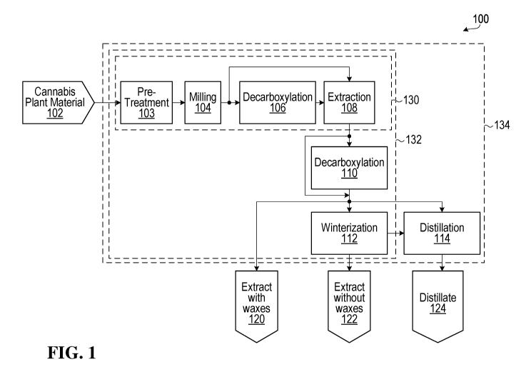
BRIEF DESCRIPTION OF THE DRAWINGS
[0226] For a more complete understanding of the present disclosure,
reference is
now made to the following description taken in conjunction with the
accompanying
drawings, in which:
[0227] Fig. 1 is a flow diagram illustrating an example process for
producing
cannabis products by processing cannabis material in accordance with an
embodiment;
[0228] Fig. 2 is a block diagram illustrating an example system for
producing
cannabis products in accordance with an embodiment;
[0229] Fig. 3 is a block diagram illustrating an integrated system for
production of
cannabis products according to another embodiment;
[0230] Figs. 4A-4E are block diagrams illustrating an example automated
cannabis material processing system;
[0231] Fig. 5 is a flow diagram illustrating a method according to another
embodiment;
[0232] Fig. 6 is a flow diagram illustrating a method according to a
further
embodiment.
[0233] In the drawings, exemplary embodiments are illustrated by way of
example. It is to be expressly understood that the description and drawings
are only for
the purpose of illustrating certain embodiments and are an aid for
understanding. They
are not intended to be a definition of the limits of the invention.
31
CA 03143765 2021-12-16
WO 2020/252593 PCT/CA2020/050859
DETAILED DESCRIPTION
[0234] For illustrative purposes, specific example embodiments will be
explained
in greater detail below in conjunction with the figures. It should be
appreciated,
however, that the present disclosure provides many applicable concepts that
can be
embodied in any of a wide variety of specific contexts. The specific
embodiments
discussed are merely illustrative and do not limit the scope of the present
disclosure.
For example, embodiments could include additional, different, or fewer
features than
shown in the drawings.
[0235] The present disclosure relates, in part, to the production of one
or more
cannabis products by processing one or more cannabis materials. The term
"cannabis
product(s)" includes goods that are produced from cannabis or hemp, which
include
plant material, oils, resins, drinks, food additives, edibles, creams, aerosol
sprays and
vaporization substances, for example. The term "cannabis material(s)" includes
cannabis plant material, which refers to plants or parts thereof, and/or
materials that are
derived from cannabis plant material and are intended for further processing
to produce
one or more cannabis products.
[0236] A cannabis material or product could include a cannabinoid in its
pure or
isolated form, or a source material that includes a cannabinoid. Examples of
source
materials include cannabis or hemp plant material (for example, flowers,
seeds,
trichomes, and kief), milled cannabis or hemp plant material, extracts
obtained from
cannabis or hemp plant material (for example, resins, waxes and concentrates),
and
distilled extracts. In some embodiments, pure or isolated cannabinoids and/or
source
materials comprising cannabinoids could be combined with water, lipids,
hydrocarbons
(for example, butane), ethanol, acetone, isopropanol, or mixtures thereof.
[0237] The term "cannabis plant" encompasses wild type cannabis sativa,
cannabis indica, cannabis afghanica, and other variants thereof, including
cannabis
species or chemovars which naturally contain different amounts of individual
cannabinoids. For example, some cannabis strains have been bred to produce
minimal
levels of THC, the principal psychoactive constituent responsible for the high
associated
32
CA 03143765 2021-12-16
WO 2020/252593 PCT/CA2020/050859
with cannabis, and other strains have been selectively bred to produce high
levels of
THC and other psychoactive cannabinoids. Also included are hemp plants and
cannabis subspecies and plants which are the result of genetic crosses, self-
crosses or
hybrids thereof. The term "cannabis extract" is also to be interpreted
accordingly as
encompassing material extracted from one or more cannabis plants.
[0238]
A particular substance could be considered a cannabis product in some
embodiments and a cannabis material in other embodiments. For example, a
cannabis
extract could be produced as a cannabis product in some embodiments, or
further
processed to produce a cannabis product in the form of a cannabis distillate
in other
embodiments.
[0239]
Uses of cannabis products include medical and/or recreational uses.
Large-scale production of cannabis products is expected to focus primarily, if
not
exclusively, on cannabis products that include active substances such as
cannabinoids.
However, cannabis products might not always include an active substance.
[0240]
As used herein, the term "cannabinoid" is generally understood to include
any chemical compound that acts upon a cannabinoid receptor. For the purpose
of this
specification, the expression "cannabinoid" means a compound such as
tetrahydrocannabinol (THC), cannabidiol (CBD), cannabigerolic acid (CBGA),
cannabigerol (CBG), cannabigerol monomethylether (CBGM), cannabigerovarin
(CBGV), cannabichromene (CBC), cannabichromevarin (CBCV), cannabidiol
monomethylether (CBDM), cannabidiol-C4 (CBD-C4), cannabidivarin (CBDV),
cannabidiorcol (CBD-C1), delta-9-
tetrahydrocannabinol (A9-THC), delta-9-
tetrahydrocannabinolic acid A (THCA-A), delta-9-tetrahydrocannabionolic acid B
(THCA-B), delta-9-tetrahydrocannabinolic acid-C4 (THCA-C4),
delta-9-
tetrahydrocannabinol-C4, delta-9-
tetrahydrocannabivarin (THCV), delta-9-
tetrahydrocannabiorcol (THC-C1), delta-7-cis-iso tetrahydrocannabivarin, delta-
8-
tetrahydrocannabinol (A8-THC), cannabicyclol (CBL), cannabicyclovarin (CBLV),
cannabielsoin (CBE), cannabinol (CBN), cannabinol methylether (CBNM),
cannabinol-
C4 (CBN-C4), cannabivarin (CBV), cannabinol-C2 (CBN-C2), cannabiorcol (CBN-
C1),
cannabinodiol (CBND), cannabinodivarin (CBVD), cannabitriol (CBT), 10-ethoxy-
33
CA 03143765 2021-12-16
WO 2020/252593 PCT/CA2020/050859
9hydroxy-delta-6a-tetrahydrocannabinol, 8, 9-d ihydroxy-delta-6a-tetrahyd
rocannabinol,
cannabitriolvarin (CBTV), ethoxy-cannabitriolvarin (CBTVE),
dehydrocannabifuran
(DCBF), cannabifuran (CBF), cannabichromanon (CBCN), cannabicitran (CBT), 10-
oxo-
delta-6a-tetrahydrocannabionol (OTHC), delta-9-cis-tetrahydrocannabinol (cis-
THC),
3,4,5,6-tetrahydro-7-hydroxy-alpha-alpha-2-trimethy1-9-n-propy1-2,
6-methano-2H-1-
benzoxocin-5-methanol (OH-iso-HHCV), cannabiripsol (CBR), trihydroxy-delta-9-
tetrahydrocannabinol (tri0H-THC), cannabinol propyl variant (CBNV), and
derivatives
thereof.
[0241]
In some embodiments, the cannabinoid is cannabidiol (CBD). For the
purpose of this specification, the expressions "cannabidiol" or "CBD" are
generally
understood to refer to one or more of the following compounds, and, unless a
particular
other stereoisomer or stereoisomers are specified, includes the compound "A2-
cannabidiol." These compounds are: (1) A5-cannabidiol (2-(6-isopropeny1-3-
methy1-5-
cyclohexen-l-y1)-5-pentyl-1,3-benzenediol); (2) A4-cannabidiol (2-(6-
isopropeny1-3-
methy1-4-cyclohexen-l-y1)-5-penty1-1,3-benzenediol); (3)
A3-cannabidiol (2-(6-
isopropeny1-3-methy1-3-cyclohexen-l-y1)-5-penty1-1,3-benzenediol); (4) A3,7-
cannabidiol
(2-(6-isopropeny1-3-methylenecyclohex-1-y1)-5-pentyl-1,3-benzenediol);
(5) A2-
cannabidiol (2-(6-isopropeny1-3-methy1-2-cyclohexen-l-y1)-5-penty1-1,3-
benzenediol); (6)
A1-cannabidiol (2-(6-isopropeny1-3-methy1-1-cyclohexen-l-y1)-5-penty1-1,3-
benzenediol);
and (7) A6-cannabidiol (2-(6-isopropeny1-3-methy1-6-cyclohexen-l-y1)-5-pentyl-
1,3-
benzenediol).
[0242]
In some embodiments, the cannabinoid is tetrahydrocannabinol (THC).
THC is only psychoactive in its decarboxylated state. The carboxylic acid form
(THCA)
is non-psychoactive. Delta-9-tetrahydrocannabinol (A9-THC) and delta-8-
tetrahydrocannabinol (A8-THC) produce the effects associated with cannabis by
binding
to the CB1 cannabinoid receptors in the brain.
[0243]
A cannabinoid may be in an acid form or a non-acid form, the latter also
being referred to as the decarboxylated form since the non-acid form can be
generated
by decarboxylating the acid form. Within the context of the present
disclosure, where
34
CA 03143765 2021-12-16
WO 2020/252593 PCT/CA2020/050859
reference is made to a particular cannabinoid, the cannabinoid can be in its
acid or non-
acid form, or be a mixture of both acid and non-acid forms.
[0244] As used herein, the term "terpene" (or "decarboxylated terpene",
which is
known as a terpenoid) is generally understood to include any organic compound
derived
biosynthetically from units of isoprene. Terpenes may be classified in various
ways,
such as by their sizes. For example, suitable terpenes may include
monoterpenes,
sesquiterpenes, or triterpenes. At least some terpenes are expected to
interact with,
and potentiate the activity of, cannabinoids. Examples of terpenes known to be
extractable from cannabis include aromadendrene, bergamottin, bergamotol,
bisabolene, borneol, 4-3-carene, caryophyllene, cineole/eucalyptol, p-cymene,
dihydroj
asmone, elemene, farnesene, fenchol, geranylacetate, guaiol, hum ulene,
isopulegol,
limonene, linalool, menthone, menthol, menthofuran, myrcene, nerylacetate,
neomenthylacetate, ocimene, perillylalcohol, phellandrene, pinene, pulegone,
sabinene,
terpinene, terpineol, 4-terpineol, terpinolene, and derivatives thereof.
[0245] Additional examples of terpenes include nerolidol, phytol,
geraniol, alpha-
bisabolol, thymol, genipin, astragaloside, asiaticoside, camphene, beta-
amyrin, thujone,
citronellol, 1,8-cineole, cycloartenol, and derivatives thereof. Further
examples of
terpenes are discussed in US Patent Application Pub. No. US2016/0250270.
[0246] Fig. 1 is a flow diagram illustrating an example process 100 for
producing
cannabis products by processing cannabis material. In Fig. 1, a rectangle
generally
denotes a step, apparatus, device, location or operation, and a pentagon
generally
denotes an input material, a processed material, or a final output product.
Process 100
includes one or more pre-treatment operations 103, an operation 104 of
milling,
operations 106, 110 of decarboxylation, an operation 108 of extraction, an
operation
112 of winterization, and an operation 114 of distillation. The example
process 100
shown in Fig. 1 is intended to be illustrative and non-limiting. Other
embodiments
include fewer, additional, and/or different operations. For example, not all
embodiments
necessarily involve pre-treatment at 103. Decarboxylation is performed at 106
and/or
110 in some embodiments, but in other embodiments decarboxylation is also or
instead
CA 03143765 2021-12-16
WO 2020/252593 PCT/CA2020/050859
performed on an extract. Some embodiments do not involve any decarboxylation
at all
during processing. Winterization at 112 and distillation at 114 are also
optional
purification operations. Some embodiments include either or both of these
operations,
and other embodiments include other purification operations such as isolation
or
separation, in combination with or instead of winterization at 112 and/or
distillation at
114. Chromatography is another example of a purification operation or process
that
may also or instead be used in some embodiments.
[0247]
In the example process 100, cannabis plant material 102 is a source or
starting material for process 100 in the example shown. In some embodiments,
cannabis plant material 102 is produced and harvested in a cannabis grow area,
and
then transferred into process 100. Other possible sources of cannabis plant
material
102 include a producer and/or a supplier of cannabis, from which cannabis
plant
material is received. Cannabis plant material 102 is intended to include any
material
that originated from a cannabis plant, including cannabis flower, trim and/or
waste for
example. Cannabis flower could also be referred to as bud, and is typically
harvested
from mature cannabis plants. Trim includes the leaves of the cannabis plant
that are
separated from the flower and stems. Trim could be harvested before the
flower, while
plants mature. Waste could include roots, stalks, stems and leaves that were
not
separated into trim, for example. In some embodiments, cannabis plant material
102 is
received from a plant part separation process that separates harvested
cannabis plants
into flower, trim and/or waste.
[0248]
Process 100 begins with harvesting, receiving, or otherwise providing a
supply of cannabis plant material 102. Such a supply of cannabis plant
material 102 is
continuous in some embodiments, to feed the process 100 as plant material is
needed.
In other embodiments, the supply of cannabis plant material 102 is semi-
continuous and
provided in batches while process 100 is ongoing so that the cannabis plant
material
does not run out. Therefore, at least a portion of process 100 could be active
and
processing material when cannabis plant material 102 is received. It should be
noted
however, that not all embodiments involve a continuous supply of cannabis
plant
material 102 or continuous processing of such material.
Semi-continuous or
36
CA 03143765 2021-12-16
WO 2020/252593 PCT/CA2020/050859
substantially continuous operation is also possible. For example, in some
embodiments
processing is continuous for a certain amount of time or material and one or
more parts
or stations in a processing line are then taken offline or shut down for
cleaning, between
different strains of cannabis plant material for instance.
[0249] Examples of optional pre-treatment operations at 103 include
drying,
freezing, or dewaxing (e.g., using chemical and/or enzymatic dewaxing). Any
one or
more of these pre-treatments could be applied at 103, depending on the
specific
cannabis product(s) to be produced, for example. Pre-treatment at 103 is
tailored to
specific extract products in some embodiments.
[0250] In some embodiments, drying involves air drying cannabis plant
material,
on one or more trays or racks for example, with or without the application of
heat by a
heater. Chemical treatment, in a treatment vessel or reactor vessel for
example, to
remove water or reduce water content is also possible. Freezing cannabis plant
material, in a chiller or freezer for example, makes the cannabis plant
material more
brittle and can also or instead be performed at 103 to prepare the cannabis
plant
material for milling. Dewaxing and digestion involve enzyme and/or chemical
treatment,
such as in a treatment vessel or reactor vessel, to reduce wax content in the
case of
dewaxing for example, in some embodiments.
[0251] Cannabis plant material 102, which has been pre-processed in some
embodiments, is sent for milling, also referred to as shredding, at operation
104.
Operation 104 could include processing at least a portion of cannabis plant
material 102
using a milling machine, for example, to reduce the physical size of the
cannabis plant
material and produce reduced size cannabis plant material. Reduced size
cannabis
plant material could increase the efficiency of other processes such as
extraction,
relative to process efficiency for non-milled cannabis plant material.
Examples of
processing of cannabis plant material 102 using a milling machine include
manual
processing, automated processing, and combined processing that is partially
manual
and partially automated.
37
CA 03143765 2021-12-16
WO 2020/252593 PCT/CA2020/050859
[0252] In some embodiments, milling at 104 is performed until a
predetermined
size of cannabis plant material has been reached. Milling time is another
possible
control parameter, and milling is performed for a predetermined milling time
in other
embodiments.
[0253] Operation 104 is illustrative of an operation for which flow rate
or feed rate
control for input material is potentially beneficial. For example, instead of
loading a
milling machine with a batch of cannabis plant material 102, in an embodiment
cannabis
plant material 102 is transferred to the milling machine at a rate that is
controlled to
substantially match a rate of milling at the milling machine and potentially
avoid
bottlenecks at the milling stage 104 in process 100.
[0254] In the present disclosure, "matching" and "substantially matching"
flow
rates and/or processing rates refer to matching such rates to within a range
that avoids
or at least reduces overflow / backup / oversupply of cannabis plant material
during
processing and/or underflow / shortage / undersupply of cannabis plant
material during
processing. Such rates need not be matched exactly, and as described elsewhere
herein components such as vessels are used in some embodiments to accommodate
at
least some rate mismatch in a processing system. It should also be appreciated
that
rates to be matched are not necessarily quantified using the same units. For
example,
in an embodiment an input rate for extraction is based on a unit of weight per
a unit of
time, whereas an output rate for extraction is based on a unit of volume per a
unit of
time, and those rates can still be matched to each other even though the flow
rate units
are different.
[0255] In some embodiments, the transfer of cannabis plant material 102
to the
milling operation 104 is, at least in part, automated. Consider, for example,
an
embodiment in which cannabis plant material 102 is loaded into a hopper or
other
vessel, and the vessel is controlled to supply cannabis plant material to a
milling
machine. The vessel could be considered a reservoir or buffer to provide a
continuous
supply of cannabis plant material 102 for the milling operation. The vessel
itself need
not necessarily be fed continuously, and is at least partially filled with
cannabis plant
material 102 intermittently in some embodiments. In some embodiments, a vessel
is
38
CA 03143765 2021-12-16
WO 2020/252593 PCT/CA2020/050859
periodically emptied for cleaning and then refilled with cannabis plant
material. Manual
and/or automated cannabis plant material supply vessel filling and/or
refilling operations
are possible.
[0256] In some embodiments, the vessel is coupled to a transfer
mechanism, to
transfer the cannabis plant material from the vessel to the milling operation.
As used
herein, "transfer mechanism" is intended to denote a device or apparatus that
moves
cannabis material from one location to another. In some embodiments, a
transfer
mechanism is used to help move matter from one processing operation and/or
machine
to a different processing operation and/or machine.
[0257] Examples of vessels and transfer mechanisms are discussed in
further
detail elsewhere herein.
[0258] Reduced size cannabis plant material is transferred from milling
operation
104 to decarboxylation operation 106 in some embodiments, to produce reduced
size
decarboxylated cannabis plant material. Decarboxylation is a process in which
acid
forms of cannabinoids are converted to their neutral forms. More specifically,
decarboxylation involves a chemical reaction that removes a carboxyl group
from
cannabinoids and releases CO2.
[0259] THC and CBD are two of the main medicinally active constituents in
cannabis. However, these constituents are present as the biologically inactive
carboxylic acids in cannabis plants. When extracting THC or CBD from cannabis
plants,
it has been the practice to convert the storage precursor compounds of THCA
and
CBDA into their more readily extractable and pharmacologically active forms.
THC and
CBD acids slowly decarboxylate over time, and applying heat increases the rate
of
decarboxylation.
[0260] In some embodiments, decarboxylation of cannabinoid acids is a
function
of time and temperature. At higher temperatures a shorter period of time will
be taken
for complete decarboxylation of a given amount of cannabinoid acid. In
selecting
appropriate conditions for decarboxylation consideration must, however, be
given to
minimizing thermal degradation of the desirable cannabinoids into undesirable
39
CA 03143765 2021-12-16
WO 2020/252593 PCT/CA2020/050859
degradation products, particularly thermal degradation of THC to cannabinol
(CBN).
Heat need not necessarily be applied during decarboxylation.
[0261]
Referring again to Fig. 1, in some embodiments process 100 involves
transferring reduced size cannabis plant material from milling operation 104
to a
decarboxylation device for carrying out operation 106.
In some embodiments,
decarboxylation involves heating the cannabis plant material, using a heater
such as a
decarboxylation oven or a heat tunnel. A heat tunnel or other heater in which
cannabis
plant material is heated as it is moved through the heater may be preferred in
a
continuous process. If the cannabis plant material for decarboxylation is in
solution or
suspension or is otherwise carried in or by a solvent, then a Continuous
Stirred-Tank
Reactor (CSTR) or Plug Flow Reactor (PFR), for example, could be used in
performing
decarboxylation operation 106. A fluidized bed reactor is another example of a
device
that could be used in some embodiments of decarboxylation. One or more of
these
types of reactors are used to implement other vessels disclosed herein, in
some
embodiments,
[0262]
In some embodiments, at least a portion of the transfer of reduced size
cannabis plant material to a decarboxylation process is automated. For
example, in an
embodiment a decarboxylation device is coupled to a milling machine via a
transfer
mechanism that is configured for transferring the reduced size cannabis plant
material
from the milling machine to the decarboxylation device.
[0263]
Reduced size cannabis plant material need not necessarily remain in
motion during the entirety of a transfer between milling operation 104 and
decarboxylation operation 106. For example, in some embodiments the reduced
size
cannabis plant material from milling operation 104 is held in a vessel after
milling but
before transfer to the decarboxylation operation 106. The vessel in this
example is a
form of reservoir or buffer to provide a continuous supply of reduced size
cannabis plant
material for the decarboxylation operation 106. For example, the vessel feeds
a
decarboxylation device using a transfer mechanism in an embodiment. The rate
of
transfer of reduced size cannabis plant material to the decarboxylation
operation 106 is
controlled in some embodiments to substantially match a rate of
decarboxylation at the
CA 03143765 2021-12-16
WO 2020/252593 PCT/CA2020/050859
decarboxylation operation 106 and/or a rate of milling operation 104, to
potentially avoid
bottlenecks around the decarboxylation operation in process 100.
[0264] In some embodiments, decarboxylation begins by setting a
decarboxylation device to a temperature of 150 C. Cannabis plant material
might not
be transferred to the decarboxylation device until it has reached a minimum
temperature
of 120 C. A temperature probe or thermometer inserted into the cannabis plant
material
enables monitoring of temperature of the cannabis plant material during
decarboxylation, and provides for control of heating of the cannabis plant
material in the
decarboxylation device until the cannabis plant material reaches a predefined
temperature, such as the temperature at which the decarboxylation process
occurs. In
some embodiments, the predefined temperature is 120 C. For cannabis plant
material
and an oven or heat tunnel, an example decarboxylation temperature range is 80
C to
150 C. For CSTR or PFR decarboxylation of cannabis plant material that is in
solution
or carried by a solvent, for example, decarboxylation is performed within a
temperature
range of 60 C to 150 C in some embodiments.
[0265] The temperature of the cannabis plant material is maintained
within a
certain range of a predefined temperature in some embodiments, such as within
4 C of
120 C.
[0266] Heating the cannabis plant material to temperatures that exceed
this
range of the predefined temperature might be undesirable. Such temperatures
could
induce other reactions, such as vaporization of cannabinoids and terpenes,
which might
affect the properties of a processed material and/or a final cannabis product.
In some
embodiments, if the cannabis plant material reaches temperatures greater than
125 C,
the set point temperature of the heater is decreased.
[0267] Weight of the cannabis plant material is also or instead monitored
during
decarboxylation in some embodiments, using one or more scales for example.
Decarboxylation can then be controlled based on weight of the cannabis plant
material,
in addition to or instead of temperature.
41
CA 03143765 2021-12-16
WO 2020/252593 PCT/CA2020/050859
[0268] Control of a decarboxylation device, such as control of the
temperature of
the decarboxylation device, is automated in some embodiments.
[0269] It should be noted that decarboxylation at operation 106 might not
be
performed in all embodiments. For example, reduced size cannabis material from
operation 104 could bypass operation 106, as illustrated in Fig. 1, and
instead proceed
directly to operation 108. Moreover, some embodiments of the present
disclosure relate
to processes for producing cannabis materials or products that do not include
an
operation for decarboxylation before an operation for extraction.
[0270] The extraction at operation 108 includes processing cannabis plant
material to obtain from the cannabis plant material one or more cannabis
extracts that
include at least one cannabinoid and/or at least one terpene. In some
embodiments,
the cannabis plant material processed in operation 108 includes reduced size
cannabis
plant material from operation 104 and/or decarboxylated cannabis plant
material from
operation 106. Examples of cannabis extracts include oils and non-oils such as
resins.
[0271] In some embodiments, operation 108 involves a fluid extraction
process,
such as a solvent extraction process to obtain a cannabis extract by
extracting cannabis
plant material with an extraction solvent. Solvent extraction involves
extracting one or
more separate compounds from a source material based on solubility of each
compound in an extraction solvent. A solvent extraction process includes
processing
or contacting cannabis plant material with an extraction solvent, which
separates one or
more cannabinoids and/or terpenes from the cannabis plant material and
captures them
in the form of a cannabis extract. Any cannabis material that remains after
extraction is
either treated as waste or subject to further processing.
[0272] In some embodiments, operation 108 includes solvent extraction
using
ethanol as the extraction solvent. In some embodiments, operation 108 includes
supercritical fluid extraction using supercritical CO2 as an extraction
solvent. Other
examples of extraction solvents include water, hexane, propane, pentane,
butane,
acetone, and other hydrocarbons. However, the embodiments described herein are
not
limited to any specific extraction solvents, or even to a solvent extraction.
Features
42
CA 03143765 2021-12-16
WO 2020/252593 PCT/CA2020/050859
disclosed herein in the context of ethanol may also be applicable to other
solvents,
and/or to a solution of a solvent with one or more other compounds such as
water.
Ethanol is intended to be a representative example of a solvent, and
references to a
solvent or any particular solvent such as ethanol are intended to be inclusive
of solvent
solutions. Solvents are fluids, but could be liquid or gas.
[0273]
For solvent extraction, operation 108 involves some sort of extractor or
extraction vessel to contact cannabis plant material with an extraction
solvent. In an
embodiment, an extractor is provided to transfer extraction solvent into
contact with the
cannabis plant material. Examples of other features provided by an extractor
in some
embodiments include pressure control, temperature control, extraction fluid
flow rate
control and/or control of other parameters of an extraction process.
In some
embodiments, running an extractor is at least partially an automated process,
involving
an operating program for the extractor that defines parameters for an
extraction run,
including one or more of time duration(s), extraction solvent(s) flow rate(s),
temperature(s) and pressure(s), for example. Such an operating program is
stored in
memory and/or on a controller of the extractor, for example, and the
controller or
another component that executes the operating program controls one or more
components of the extractor during a run.
[0274]
In fluid extraction using ethanol, ethanol immerses and/or flows through
cannabis plant material, and captures cannabinoids, terpenes, and/or other
substances
such as waxes in the cannabis plant material that are soluble in ethanol. In
some
embodiments, a mixture of ethanol and cannabis plant material is agitated by
an
extractor to encourage dissolution of at least cannabinoids, and possibly
terpenes, in
the ethanol.
[0275]
Fluid extraction using ethanol under warm conditions (above room
temperature, > 25 C.), room temperature conditions (20-25 C.), cool
conditions (below
room temperature, < 20 C.) or super-cooled conditions (< -20 C., e.g.,
cooled in dry-
ice) are possible. In an embodiment, ethanol is boiled in a flask or pot,
cooled in a
condensing coil, and then dripped through cannabis plant material to capture
cannabinoids and terpenes. Such a warm ethanol process improves efficiency of
fluid
43
CA 03143765 2021-12-16
WO 2020/252593 PCT/CA2020/050859
extraction, in terms of extraction time and/or amount of ethanol consumed for
example,
at least for cannabinoids and terpenes that have a higher solubility in warm
ethanol.
Decarboxylation is another potential benefit of warm-ethanol extraction, in
that warm
ethanol can cause decarboxylation of the extracted cannabinoid(s), as part of
extraction
rather than in a separate process. Therefore, in some embodiments, an
extracting
operation involves a warm solvent extraction process that further causes
decarboxylation of at least one cannabinoid in a cannabis extract.
[0276] Although fluid extraction using ethanol is possible under room
temperature, cool and/or super-cooled conditions, the efficiency of an
extraction
process in terms of extraction time and ethanol consumed, for example, is
potentially
reduced relative to fluid extraction under warm conditions as a result of
lower solubility
of cannabinoids, terpenes and/or waxes in cooler ethanol.
[0277] In supercritical fluid extraction with CO2, an extraction run
involves sealing
an extraction chamber that contains cannabis plant material, and allowing the
extraction
chamber to fill up with CO2, by adjusting inlet and outlet regulating valves
on the
extractor for example. In some embodiments, a CO2 monitor is used to monitor
the
amount of CO2 in the extraction chamber. After the extraction chamber is
filled to a
target CO2 level or concentration and has reached a stable pressure, as
monitored by
one or more pressure sensors, a chamber heater is started. In some
embodiments, the
chamber is left for a predefined time, such as 30 minutes, to allow the
chamber to reach
a stable temperature, as monitored by one or more temperature sensors for
example.
[0278] With stable temperature and pressure, an extractor could then be
run to
produce extract from the cannabis plant material. Running an extractor could
include
further adjusting heat and/or pressure in the extractor to convert gaseous CO2
into a
supercritical fluid that dissolves cannabinoids and/or terpenes in the
cannabis plant
material. After the extraction run is complete, the extraction chamber could
be purged
with CO2 to collect the produced cannabis extract.
[0279] At an input side of operation 108, in some embodiments reduced
size
cannabis plant material from operation 104 is transferred to the extraction
operation,
44
CA 03143765 2021-12-16
WO 2020/252593 PCT/CA2020/050859
and in other embodiments decarboxylated cannabis plant material from operation
106 is
also or instead transferred to the extraction process. This transfer is at
least partially
automated in some embodiments.
[0280] For example, an extractor could be coupled to a decarboxylation
heater
via a transfer mechanism that is configured for transferring the
decarboxylated cannabis
plant material from the decarboxylation device to the extractor. An extractor
could also
or instead be coupled to a milling machine via another transfer mechanism
configured
for transferring the reduced size cannabis plant material from the milling
machine to the
extractor. The rate(s) of transfer could be controlled to substantially match
a rate of
extraction in the extractor and thereby potentially avoid processing
bottlenecks and/or
cannabis material supply shortages or underflows.
[0281] Processed cannabis plant material from operation 104 and/or
operation
106 could be held in one or more vessels before or during transfer to
extraction at
operation 108. Such a vessel is a form of a reservoir or buffer to provide a
continuous
supply of cannabis plant material for extraction, with some capacity to
accommodate
transfer / processing rate mismatch.
[0282] In some embodiments, an extraction solvent is used to transfer
cannabis
plant material from milling and/or decarboxylation to extraction. For example,
milling
operation 104 could include contacting cannabis plant material with an
extraction
solvent. The extraction solvent could be added before, during and/or after
milling, and
could be added by manually pouring the solvent into the milling machine and/or
by
using one or more components such as pipes, pumps and/or valves to transfer
the
extraction solvent into a milling machine. Any or all reduced size cannabis
plant
material produced at operation 104 could become at least partially dissolved
and/or
suspended in the extraction solvent, creating a solution and/or suspension of
reduced
size cannabis plant material. The fluidic properties of the extraction solvent
could allow
the cannabis plant material to flow from the milling machine to an extractor.
As such,
the extraction solvent could be considered a form of carrier or vehicle to
carry any or all
reduced size cannabis material from operation 104 to operation 108.
CA 03143765 2021-12-16
WO 2020/252593 PCT/CA2020/050859
[0283]
Using an extraction solvent to transfer reduced size cannabis plant
material from a milling process to an extraction process could also have other
uses. For
example, certain waxes and/or other compounds in cannabis plant material could
form a
tacky residue that adheres to the inside of a milling machine during a milling
process.
When this residue builds up to a certain level, the efficiency and/or
effectiveness of the
milling process could be reduced, and the milling process might be interrupted
or
stopped to clean the milling machine. An extraction solvent that includes
ethanol, for
example, could function as a solvent for this residue, and could be used to
clean the
milling machine during a stoppage. In some embodiments, an extraction solvent
is also
or instead used to clean a milling machine during use, when the milling
machine is
actively milling cannabis plant material. Contacting the cannabis plant
material with an
extraction solvent during milling could wash waxes and/or other residues from
a milling
machine as the machine operates, potentially reducing the length and/or
frequency of
milling machine stoppages for cleaning.
[0284]
In some embodiments, solvent exiting a milling machine contains
dissolved and/or suspended reduced size cannabis plant material, flows into an
extractor, and is used as an extraction solvent during solvent extraction.
Additional
solvent might or might not be added for extraction at 108. The solvent that
carries the
reduced size cannabis plant material into an extractor is sufficient to also
perform
extraction in some embodiments. However, in other embodiments, additional
solvent is
added during solvent extraction. Moreover, the solvent that carries the
reduced size
cannabis plant material to the extractor might not be used for extraction in
all
embodiments. For example, in an embodiment the reduced size cannabis plant
material is filtered out of the solvent and transferred to the extractor, and
fresh solvent
and/or a different extraction solvent is then added and used for extraction.
[0285]
Another potential use of solvent-based extraction is for performing
decarboxylation.
For example, if warm ethanol is used during extraction, then
decarboxylation might occur during extraction. Thus, process 100 might not
perform a
separate decarboxylation operation at 106, 110 in the case that warm ethanol
extraction
is performed at operation 108, for example. If room temperature, cool, or
super-cooled
46
CA 03143765 2021-12-16
WO 2020/252593 PCT/CA2020/050859
ethanol is used for extraction, then decarboxylation of a mixture of ethanol
and cannabis
plant material could be performed at operation 106. In some embodiments,
operation
106 includes receiving a mixture of cannabis plant material and ethanol from
operation
104. Decarboxylation could then be performed at operation 106 by heating this
mixture
in a flask or other container to induce decarboxylation.
[0286] Solvent-based extraction is one example of an extraction process.
Mechanical extraction to separate trichomes from cannabis plant material, for
example,
may be used in some embodiments. Other embodiments could employ other types of
extraction, and/or multiple types of extraction.
[0287] In some embodiments, the cannabis extract(s) produced by
extraction at
106 are sent to operation 110 for decarboxylation, to produce decarboxylated
cannabis
extracts. For example, decarboxylation is performed at 110 in some embodiments
in
which decarboxylation is not performed at 106 and does not take place during
extraction
at 108. In the case that cannabis extract(s) are mixed with an extraction
solvent,
operation 108 could include heating the mixture in a flask or other container,
for
example, to induce decarboxylation. However, operation 110 need not be
performed in
all embodiments. Therefore, the cannabis extract(s) from operation 108 bypass
operation 110 in some embodiments, and this is illustrated in Fig. 1.
[0288] Although not shown in Fig. 1, decarboxylation could be implemented
following winterization at operation 112 and/or distillation at operation 114.
However,
some embodiments of the present disclosure relate to processes for producing
cannabis products that do not involve decarboxylation after extraction.
Furthermore,
some processes might not include decarboxylation at all. For example, the
production
of cannabis-based vaporization substances might not include decarboxylation
because
decarboxylation could occur when a user vaporizes the vaporization substances.
[0289] An output of the extraction at operation 108, and/or an output of
the
decarboxylation at operation 110, could be a cannabis extract 120 that
includes waxes
and/or lipids. These waxes and/or lipids could include wax esters, glycerides,
and/or
unsaturated fatty acids that were extracted from cannabis plant material along
with the
47
CA 03143765 2021-12-16
WO 2020/252593 PCT/CA2020/050859
cannabinoids and/or terpenes. Such waxes and/or lipids are also referred to as
waxy
ballast, and tend to hinder an extract from forming a refined liquid state.
Extract 120,
also referred to as a crude extract, a concentrate or a resin, is an example
of a possible
cannabis-containing end product of process 100, and is packaged and shipped to
end
users or other licensed producers in some embodiments. Even though an extract
120 is
a cannabis product that is produced by the process 100 in some embodiments,
the
extract is further processed in some embodiments to produce cannabis-infused
consumer products, for example. The following is a non-exhaustive list of
examples of
cannabis-infused consumer products that could be produced using a cannabis
material
or product as an ingredient:
= Cannabis-infused beverages (beverages incorporating cannabinoid-
containing
substance(s) and which are intended to be consumed in the same manner as
beverage drinks);
= Cannabis-infused edibles (products incorporating cannabinoid-containing
substance(s) and which are intended to be consumed in the same manner as
food);
= Cannabis-infused topicals (products that incorporate cannabinoid-
containing
substance(s) and which are intended to be used on external body surfaces, such
as skin, hair, and/or nails);
= Cannabis-infused mucoadhesive delivery systems (products that incorporate
cannabinoid-containing substance(s) and which are intended to be used on
mucosa body surfaces, such as mouth, anal, nasal and vaginal cavities); and
= Cannabis-infused vaping oil (oil products incorporating cannabinoid-
containing
substance(s) and which are intended to be consumed in a vaping device, such
as an electronic cigarette).
[0290] The winterization operation 112 is an operation to winterize a
cannabis
extract in the presence of a winterization solvent to obtain a winterized
extract.
Winterization is also be referred to as a secondary extraction, which extracts
or
48
CA 03143765 2021-12-16
WO 2020/252593 PCT/CA2020/050859
removes one or more undesirable components from a cannabis extract. For
example,
in some embodiments winterization reduces the amount of, or even rids an
extract of,
any or all waxes and/or lipids, while retaining the more polar cannabinoid
molecules.
[0291]
A winterization solvent is incorporated with a cannabis extract such that
the cannabis extract is in contact with the winterization solvent, and a
mixture of
cannabis extract and winterization solvent is formed.
For example, in some
embodiments a winterization solvent such as ethanol is mixed with the cannabis
extract
during operation 112. Other examples of winterization solvents include
ethanol/water
solutions and acetone, and other solvents are also possible. Additional
solvent
examples are provided elsewhere herein.
[0292]
Also or alternatively, the cannabis extract could be mixed with the
winterization solvent before operation 112.
For example, ethanol is mixed with the
cannabis extract during a prior extraction process and/or milling process in
some
embodiments.
[0293]
Operation 112 also involves cooling the mixture of winterization solvent
and cannabis extract in some embodiments. In other embodiments, the
winterization
solvent is cooled before it is mixed with the cannabis.
[0294]
Although described herein primarily in the context of removal of
undesirable components from a cannabis plant extract, winterization is also or
instead
used for other purposes in some embodiments. For example, in some embodiments
winterization is used to flash-freeze cannabis plant material as an
alternative to drying in
pre-treatment before milling and/or as a pre-extraction processing operation
after
milling.
[0295]
Winterization at 112 operates on a principle that undesirable
component(s) in a cannabis plant extract have precipitation temperature(s) at
which the
undesirable component(s) precipitate out of solution in a winterization
solvent but one or
more cannabinoids and/or terpenes remain in solution. Therefore, the
undesirable
component(s) precipitate out of the solution while the cannabinoid(s) and/or
terpene(s)
49
CA 03143765 2021-12-16
WO 2020/252593 PCT/CA2020/050859
remain dissolved. The undesirable component(s) can then be removed, by
filtering for
example, from the winterization solvent. In some embodiments, winterization
also or
instead releases any or all other trapped solvents, such as extraction
solvents, from a
cannabis extract.
[0296]
Ethanol is polar solvent that is used as a winterization solvent in ethanol
winterization or ethanolic precipitation, for example.
However, other winterization
solvents are also possible, and examples are provided herein. In some
embodiments,
ethanol winterization is used to separate and remove waxy ballast, and thereby
purify a
crude cannabis extract by removing or at least reducing such undesirable
components
as waxes and/or lipids.
[0297]
A winterization chiller is used to carry out at least a portion of the
winterization process at operation 112 in some embodiments. A winterization
chiller
cools a mixture of winterization solvent and cannabis extract to induce the
precipitation
of the undesirable component(s). Any of various types of refrigeration and/or
freezing
equipment, including refrigerators, freezers, and/or cooling or freezing
tunnels which
might be preferred for continuous processes, are suitable for implementation
of a
winterization chiller.
[0298]
Removing the waxy ballast from the cannabis extract could include chilling
a mixture of cannabis extract and winterization solvent to a temperature less
than or
equal to about 0 C, alternatively less than or equal to about -10 C,
alternatively less
than or equal to about -20 C, for a time period. The time period may be at
least 1 hour,
alternatively at least about 24 hours, alternatively at least about 48 hours,
alternatively
at least about 50 hours, alternatively at least about 72 hours. After the
chilling period,
the crude cannabis extract can be cold-filtered to remove the waxy ballast.
For
example, a filter with vacuum assist and/or pressure assist could be initially
used to
remove plant material that is insoluble, and secondly the crude extract could
be run
through syringe filters (for example, 0.45 and/or 0.2 micron filters), to
filter out
components such as remaining plant material and/or bacteria that may be
present. In
CA 03143765 2021-12-16
WO 2020/252593 PCT/CA2020/050859
some embodiments, the winterization station 220 also includes one or more
centrifuges
to separate waxy ballast from the crude cannabis extract.
[0299] In some embodiments, a winterization station also includes one or
more
mixture vessels. Mixing during winterization may be useful, for example, to
aid in
avoiding or reducing clogging and maintaining flow as a crude cannabis extract
is
cooled.
[0300] In the example process 100, cannabis extract is transferred from
operation
108 and/or from operation 110 to winterization at 112. In some embodiments, at
least a
portion of the transfer to the winterization process is automated. For
example, a
winterization chiller could be coupled to a decarboxylation device via a
transfer
mechanism that is configured for transferring the decarboxylated cannabis
extract from
the decarboxylation device to the winterization chiller. A winterization
chiller could also
or instead be coupled to an extractor via another transfer mechanism
configured for
transferring the cannabis extract from the extractor to the winterization
chiller. The
rate(s) of transfer, to a precipitation separator that is part of a
winterization station for
example, could be controlled to substantially match a rate of winterization in
the
winterization chiller and potentially avoid bottlenecks and/or cannabis
material shortage
at an input and/or output of the winterization at 112.
[0301] In some embodiments, cannabis extract is held in one or more
vessels
before transfer to a winterization chiller. Any such vessel could be
considered a
reservoir or buffer to provide a continuous supply of cannabis extract for
winterization
and at least some capacity to accommodate mismatch between transfer rate(s)
and/or
between transfer rate(s) and winterization rate.
[0302] In some embodiments, extraction solvent helps transfer cannabis
extract
from an extractor to a winterization chiller. For example, an extraction
solvent could
help reduce the viscosity of the extract and facilitate the flow of cannabis
extract to the
winterization chiller. The extraction solvent could be added before, during
and/or after
the extraction operation 108. For example, any or all ethanol that is added
during the
51
CA 03143765 2021-12-16
WO 2020/252593 PCT/CA2020/050859
milling operation 104 and/or the extraction operation 108 could dissolve
and/or suspend
a cannabis extract, and thus reduce the viscosity of the cannabis extract.
[0303]
An output of the winterization operation 112 is a cannabis extract 122 that
has a lower amount or concentration of one or more undesirable components. In
some
embodiments, a winterized cannabis extract is substantially free of
undesirable
components such as waxes and/or lipids. Extract 122 is another example of a
possible
cannabis-containing end product of process 100, which is packaged and shipped
to end
users in some embodiments. Extract 122 could also or instead be transferred
for further
processing to produce cannabis-infused consumer products, examples of which
are
provided elsewhere herein.
[0304]
Operation 114 involves distillation to purify, isolate and/or crystallize at
least one cannabinoid from a cannabis extract. Distillation could include the
use of a
distillation column or other form of distiller, for example.
[0305]
Inputs to distillation operation 114 could include cannabis extract
transferred from operation 108, operation 110 and/or operation 112.
In some
embodiments, such transfers involve holding cannabis extract from operation
108,
operation 110 and/or operation 112 in one or more vessels. Any or all of these
vessels
provide a form of reservoir or buffer, to enable a continuous supply of
cannabis extract
for distillation, and/or to accommodate at least some mismatch in rate(s) of
flow and/or
processing of cannabis material through the example process 100.
[0306]
In some embodiments, at least a portion of the transfer of cannabis extract
to distillation is automated. For example, a distiller could be coupled to an
extractor, a
decarboxylation device, and/or a winterization chiller via one or more
transfer
mechanisms configured for transferring cannabis extract from the extractor,
decarboxylation device, and/or winterization chiller to the distiller. The
rate(s) of transfer
of cannabis extract are controlled in some embodiments to substantially match
a rate of
distillation in the distiller to potentially avoid buildup and/or shortage of
cannabis
material at an input and/or output of distillation at 114.
52
CA 03143765 2021-12-16
WO 2020/252593 PCT/CA2020/050859
[0307]
In some embodiments, a winterization solvent and/or an extraction solvent
are used to help transfer cannabis extract to the distiller from a
winterization chiller
and/or an extractor. As noted above, ethanol or other appropriate solvent(s)
could be
used as both an extraction solvent and a winterization solvent, and therefore
a solvent
could help transfer cannabis extract from an extractor and/or a winterization
chiller to
the distiller. In such embodiments, one or more cannabinoids and/or terpenes
are
separated from a solvent by distillation, or the solvent is also or instead
removed
between any of operations 104, 106, 108, 112, 114 by filtering cannabis plant
material
and/or cannabis extract from the solvent, for example. In some embodiments,
the
solvent is removed into order to collect extracts 120, 122.
[0308]
An output of the distillation at operation 114 is a distillate 124 that
substantially consists of a single pure cannabinoid or a mixture of
cannabinoids. For
example, in some embodiments the output distillate includes a single
cannabinoid
having at least 90% purity, or at least 95% purity, or at least 98% purity, or
at least 99%
purity, or being almost 100% pure. Distillate 124 is another example of a
possible
cannabis-containing end product of process 100, and is packaged and shipped to
end
users in some embodiments. Distillate 124 could also or instead be further
processed
to produce cannabis-infused consumer products, for example, such as those
described
elsewhere herein.
[0309]
The process 100 is at least partially automated in some embodiments, to
provide a continuous process. Process automation in some embodiments allows
one or
more components, such as milling machines, decarboxylation devices,
extractors,
winterization chillers and/or distillers, to be operated more efficiently than
in
implementations that require a higher degree of human intervention. For
example, in
some embodiments automation enables cannabis material to be transferred to,
from,
and/or between operations at rates that are determined based on actual
operating
conditions or parameters at any of various locations or positions in a process
or
processing system.
Another potential benefit of automation is to limit human
involvement in a cannabis production process, thereby reducing the likelihood
of human
53
CA 03143765 2021-12-16
WO 2020/252593 PCT/CA2020/050859
error and/or reducing contamination risk associated with cannabis material
handling by
personnel.
[0310] The foregoing description of process 100 illustrates that some
compounds, such as ethanol or other solvent(s), could help facilitate a
continuous
process. Example uses of solvents include: use as a cleaning solvent for
cleaning a
milling machine at operation 104 (for example through high pressure steam
processes),
use as an extraction solvent at operation 108, use as a winterization solvent
at
operation 112, and use in helping perform decarboxylation at any or all of
operations
106, 108, 110. A solvent is recovered and reused for multiple operations in
some
embodiments, potentially reducing the overall amount of solvent consumed
relative to
conventional processes.
[0311] In some embodiments, solvent is also involved in transferring
cannabis
materials. As an example, a solution and/or suspension of cannabis plant
material
and/or cannabis extracts in a solvent is used for transfers between any or all
of
operations 103, 104, 106, 108, 110, 112 and 114, in some embodiments. Since
the
solvent could confer at least some fluidic properties to the cannabis plant
material
and/or cannabis extracts, any of various fluidic components could be used to
transfer
the cannabis plant material and/or cannabis extracts between different
processes.
Examples of fluidic components include pipes, valves and pumps. These fluidic
components could be automated, and therefore potentially reduce the need for
manual
operations in a process or processing system.
[0312] In some embodiments, the process 100 is made continuous at least
in part
by controlling one or more processes or processing devices / equipment so that
there is
a constant supply of input material for each of operations 103, 104, 106, 108,
110, 112
and 114. For example, operation 108 could include providing, and/or the use
of, an
extraction vessel that contains a cannabis plant extract in an extraction
solvent. This
extraction vessel could be a component of an extractor, or a separate vessel
thereto.
[0313] Operation 108 could further include incorporating a cannabis plant
material and a volume of extraction solvent into the vessel, and continuously
54
CA 03143765 2021-12-16
WO 2020/252593 PCT/CA2020/050859
withdrawing a portion of the extraction solvent containing the extract from
the vessel.
By continuously withdrawing a portion of the extraction solvent at a certain
rate,
operation 108 could substantially maintain a constant volume of cannabis plant
material
and extraction solvent in the vessel. In some embodiments, the volume is
maintained
within a certain range of a target volume, above a minimum volume, below a
maximum
volume, and/or at a volume relative to one or more thresholds.
Substantially
maintaining a constant volume in this example is one way, but not the only
way, to
implement a continuous process. Volume could vary to at least a certain
degree,
without vessel overflow or emptying for example, in a continuous process.
[0314]
The rate at which the extraction solvent is withdrawn in this example could
be predetermined, and/or sensors could actively adjust the rate to aid in
maintaining a
constant volume in the vessel. The withdrawn portion of the extraction solvent
could
transfer extract from the extraction vessel in operation 108 to winterization
operation
112, for example. Also or alternatively, the withdrawn portion of the
extraction solvent
could transfer extract from the extraction vessel in operation 108 to
distillation operation
114.
[0315]
Although the embodiments described in relation to Fig. 1 primarily discuss
the use of ethanol as an extraction solvent and a winterization solvent, this
need not be
the case in all embodiments. Other solvents could also or instead be used for
cleaning
a milling machine, serving as an extraction solvent during extraction, serving
as a
winterization solvent during winterization, and/or aiding in the transfer of
cannabis plant
material and/or cannabis extracts. Examples are disclosed elsewhere herein.
[0316]
As noted above, the process 100 may be made continuous at least in part
by controlling one or more processes or processing devices / equipment so that
there is
a constant supply of input material for each of operations 103, 104, 106, 108,
110, 112
and 114. In general, any operation, process, component, station, substation,
or system
may receive a continuous supply, continuous stream, continuous flow, or
continuous
transfer of an input cannabis material for processing and/or provide a
continuous
supply, continuous stream, continuous flow, or continuous transfer of an
output
processed cannabis material. Examples of input cannabis material for
processing and
CA 03143765 2021-12-16
WO 2020/252593 PCT/CA2020/050859
output processed cannabis material are provided elsewhere herein. Various
options in
respect of operations, processes, components, stations, or substations that
may be
coupled to each other or otherwise receive cannabis material from or provide
cannabis
material to each other are also provided elsewhere herein. Cannabis material,
which
may take any of various forms dependent upon a particular operation, process,
component, station, or substation, may be received in or received as a
continuous
supply, continuous stream, continuous flow, or continuous transfer. Cannabis
material
may also or instead be transferred in or transferred as a continuous supply,
continuous
stream, continuous flow, or continuous transfer to any operation, process,
component,
station, or substation.
[0317] Some aspects of the present disclosure relate to the integration
of
processes that are conventionally implemented as separate and distinct
processes. For
example, Fig. 1 illustrates possible integrated operations 130, 132, 134 using
dashed
rectangles. Integrated operation 130 includes any two or more of operations
103, 104,
106, 108. As such, any two or more of operations 103, 104, 106, 108 could be
considered sub-operations of integrated operation 130. Similarly, integrated
operation
132 includes any two or more of operations 103, 104, 106, 108, 110, 112, and
integrated operation 134 includes any two or more of operations 103, 104, 106,
108,
110, 112, 114.
[0318] To implement integrated operations 130, 132, 134, several
different
systems and/or devices are integrated or combined. Examples of system
integration
include coupling different systems together, and providing a single system
that performs
two or more of the operations illustrated in Fig. 1.
[0319] One potential benefit of integrated operations such as those
illustrated at
130, 132, 134 is reducing the number of manual steps in process 100. For
example, in
some embodiments integrated operations 130, 132, 134 provide automated
operations
that produce cannabis products with little to no human involvement.
[0320] Integrated operations 130, 132, 134 illustrated in Fig. 1
represent
examples, and should not be considered limiting in any way. In general,
integration is
56
CA 03143765 2021-12-16
WO 2020/252593 PCT/CA2020/050859
potentially applicable to any of operations 103, 104, 106, 108, 110, 112, 114
of Fig. 1 in
any of a number of different combinations.
[0321] The foregoing description concentrates primarily on processing.
Systems
and devices for producing cannabis products are described in further detail
below. Fig.
2 is a block diagram illustrating an example system 200 for producing cannabis
products. In some embodiments, system 200 is used to implement processing
consistent with process 100 of Fig. 1.
[0322] System 200 includes multiple processing stations 203, 204, 208,
212, 216,
220, 224, multiple vessels 201, 202, 206, 210, 214, 218, 222, and multiple
transfer
mechanisms 230, 231, 232, 233, 234, 236, 238, 240, 242, 244, 246, 248, 250,
252, 254,
256, 258 interconnecting vessels and processing stations.
[0323] Stations 203, 204, 208, 212, 216, 220, 224 could be discrete
subsystems
or devices for performing respective processes. However, as discussed in
further detail
herein, one or more of stations 203, 204, 208, 212, 216, 220, 224 could be
integrated
into a single station to perform multiple different processes. In a processing
system that
implements at least partially continuous processing and/or integrated
processing
stations, multiple stations 203, 204, 208, 212, 216, 220, 224 are co-located
as part of a
processing or production line for example. Embodiments in which processing
stations
203, 204, 208, 212, 216, 220, 224 are at different locations, such as in
different rooms
or buildings or even at different sites, are also possible. As noted elsewhere
herein, not
all embodiments necessarily involve continuous or integrated processing.
[0324] The vessels 201, 202, 206, 210, 214, 218, 222 are provided to hold
or
store cannabis materials or cannabis products in system 200. For example, in
an
embodiment a vessel includes an intake or input port through which a cannabis
material
or cannabis product is received, an internal space for holding the cannabis
material or
cannabis product, and an outlet or output port through which the cannabis
material or
cannabis product is released or dispensed from the vessel. As used herein, a
vessel is
intended to denote any type of holding container in which a cannabis material
or
cannabis product is or could be contained. This includes holding containers
that are
57
CA 03143765 2021-12-16
WO 2020/252593 PCT/CA2020/050859
used for storing cannabis materials or cannabis products before, during and/or
after
processing, as well as containers that store cannabis products for sale.
Hoppers, bins,
and tanks are examples of vessels that are suitable for use in a production
setting such
as system 200. Vessels could be constructed from one or more materials such as
wood, paper, cardboard, plastic, glass, for example.
[0325] In some embodiments, vessels are sealed or sealable, to seal
cannabis
materials or cannabis products from their environment. Examples of vessel
seals
include caps, lids, and covers. Vessels could also or instead be sealed with
one or
more of: foil seals, heat seals, induction seals, and shrink wrap, for
example. In some
embodiments, seals are tamper-resistant or tamper-proof, as in the case of a
tamper-
proof induction seal, for example.
[0326] Vessels that are at least partially open to a surrounding
environment are
also possible.
[0327] The present disclosure is not limited vessels of any particular
physical
dimension(s). Vessels of any of a variety of different shapes, including
cylindrical,
rectangular, and/or triangular, for example, could be implemented in a
processing
system such as 200. Similarly, volume of a vessel is not limited in the
embodiments
described herein. A vessel could have a volume less than about 1L, less than
about 5L,
less than about 10L, less than about 20L, less than about 50L, less than about
100L,
less than about 200L, less than about 500L, or less than about 1000L, for
example.
[0328] In general, vessel characteristics are chosen or selected based on
any of
various processing system or processing criteria. In some embodiments vessel
size is
determined based on one or more of: physical space available to build a
processing or
production line, the type of cannabis material or cannabis product that is to
be held or
stored (cannabis plant material before milling occupies more space than
reduced size
cannabis plant material after milling for example), the amount of cannabis
material or
cannabis product that is to be held or stored (it may be desirable to store a
larger
amount of input cannabis material for a faster processing station than for a
slower
processing station, and/or to have a larger holding or storage capacity for
processed
58
CA 03143765 2021-12-16
WO 2020/252593 PCT/CA2020/050859
cannabis material from a faster processing station than from a slower
processing
station, for example), and/or how cannabis materials or cannabis products are
to be
separated or packaged (for example, it might be necessary to maintain
separation or
trackability between different lots or amounts of cannabis materials or
cannabis
products in order to satisfy regulatory and/or other requirements, which in
turn dictates a
maximum vessel storage capacity at one or more stations in a processing
system).
[0329] Other vessel characteristics such as material construction, type,
and
sealed or unsealed design, are also potentially determined or selected based
on any of
various criteria. Vessel construction and/or type could depend upon the type
of
cannabis material or cannabis product that is to be held or stored, and/or the
particular
transfer mechanism(s) or processing station(s) to which a vessel is to be
coupled, for
example. A sealed vessel might be preferred over a partially open or unsealed
vessel
for cannabis materials or cannabis products that are sensitive to
environmental
conditions and/or for longer term holding or storage above a time threshold
such as
beyond an expected processing time to complete a production run.
[0330] Other embodiments in which these and/or other criteria are taken
into
account in vessel design, and/or other aspects of processing system design,
are also
possible.
[0331] Transfer mechanisms 230, 231, 232, 233, 234, 236, 238, 240, 242,
244,
246, 248, 250, 252, 254, 256, 258 are provided to move cannabis materials or
cannabis
products throughout system 200. For example, a transfer mechanism could be
used to
move a cannabis material or cannabis product from one station or vessel to
another
station or vessel. Active transfer mechanisms and passive transfer mechanisms
are
possible.
[0332] An active transfer mechanism is powered or driven to impart motion
to a
cannabis material or cannabis product. An example of an active transfer
mechanism is
a pump, for a fluid or liquid-like cannabis material or cannabis product such
as a
cannabis extract and/or a cannabis material or cannabis product that is
dissolved and/or
suspended in a solvent or other liquid for example. Conveyors are another
example of
59
CA 03143765 2021-12-16
WO 2020/252593 PCT/CA2020/050859
an active transfer mechanism, for solids such as cannabis plant material or
milled
cannabis plant material for example. Non-limiting examples of conveyors
include
conveyor belts, roller conveyors, vibrating conveyors, chain conveyors, bucket
conveyors and screw or auger conveyors.
[0333]
A gravity feed, from a hopper through a bottom or lower outlet for
example, is illustrative of a passive transfer mechanism. A passive transfer
mechanism
enables transfer of a cannabis material or cannabis product, but does not
itself induce
motion to the cannabis material or cannabis product. A hollow structure that
is capable
of transporting matter is referred to generally herein as a pipe or conduit,
and
represents another example of a passive transfer mechanism. Pipes could be
straight,
bent or curved, for example. Pipes are also not limited to any particular
cross-sectional
shape or size. For example, circular, rectangular and triangular cross-
sections are
possible.
[0334]
In some embodiments, a transfer mechanism includes both one or more
active components and one or more passive components. As an example, in a
transfer
mechanism in which a pump forces a fluid through a conduit or pipe, the pump
is an
active component and the conduit or pipe is a passive component.
[0335]
Other components are also provided in some embodiments of transfer
mechanisms. For example, some embodiments include one or more valves to
control
the flow of cannabis materials or cannabis products into vessels, into pipes,
out of
vessels, and/or out of pipes.
[0336]
Although transfer mechanisms and vessels are illustrated in Fig. 2 as
separate components, this might not always be the case. In some embodiments, a
transfer mechanism includes one or more vessels. For example, in an
embodiment,
transfer mechanism 232 includes vessel 206. A pipe and a vessel could even be
integrated together as a combined, unitary component.
Moreover, in another
embodiment, transfer mechanisms 232, 234 and vessel 206 are part of the same
transfer mechanism. Similar comments also apply to transfer mechanisms 230,
231,
CA 03143765 2021-12-16
WO 2020/252593 PCT/CA2020/050859
233, 236, 238, 240, 242, 244, 246, 248, 250, 252, 254, 256, 258 and vessels
201, 202,
210, 214, 218, 222.
[0337] Embodiments in which a processing station or subsystem includes
one or
more vessels and/or one or more transfer mechanisms are also possible. In an
embodiment, a transfer mechanism, such as a gravity feed or pipe for example,
is built
into or otherwise integrated with a processing station to provide at least
part of an input
or output transfer mechanism for the processing station.
[0338] Characteristics of transfer mechanisms are chosen or selected
based on
any of various processing system or processing criteria. In some embodiments
transfer
mechanism type, size, and/or transfer or driving capacity are determined based
on one
or more of: suitability for automation (an active transfer mechanism might
provide more
granular and/or reliable control than a passive transfer mechanism for
example),
physical space available to build a processing or production line, the type of
cannabis
material or cannabis product that is to be transferred (a conveyor for solids
such as
cannabis plant material or a pump for fluids or liquid-like cannabis materials
or cannabis
products for example), the amount of cannabis material or cannabis product
that is to be
transferred (larger pipe size, pump size, and/or conveyor size for moving
larger
amounts of cannabis material to and/or from a faster processing station that
processes
material faster than a slower processing station), and/or transfer speed (to
transfer
cannabis materials or cannabis products at a speed that is expected to achieve
or at
least be conducive to meeting target parameters for such conditions as
settling,
dissolution, precipitation, change in temperature, change in pressure,
filtering,
evaporation, and/or condensation during transfer, for example).
[0339] Other transfer mechanism characteristics such as material
construction
and/or shape, are also potentially determined or selected based on any of
various
criteria. Such criteria include those described above or elsewhere herein,
and/or
possibly others such as the particular vessel(s) or processing station(s) to
which a
transfer mechanism is to be coupled, for example.
61
CA 03143765 2021-12-16
WO 2020/252593 PCT/CA2020/050859
[0340]
Other embodiments in which these and/or other criteria are taken into
account in transfer mechanism design, and/or other aspects of processing
system
design, are also possible.
[0341]
Examples of systems, devices, or equipment to carry out pre-treatment,
milling, decarboxylation, extraction, winterization, and distillation are
provided above,
with reference to these operations in Fig. 1. These examples are illustrative
of possible
options for implementing pre-treatment station 203, milling station 204,
decarboxylation
station 208 and/or 216, extraction station 212, winterization station 220, and
distillation
station 224 in Fig. 2. Additional and/or more detailed examples are also
provided
below.
[0342]
In the example system 200, vessel 202 is provided to hold cannabis plant
material that is used as a source material for the system. This cannabis plant
material
could be cannabis plant material 102 described above with reference to Fig. 1,
for
example. In some embodiments, harvested cannabis plant material is placed in
vessel
201, transferred to pre-treatment station 203 by transfer mechanism 231, pre-
treated at
pre-treatment station 203, and then transferred to vessel 202 by transfer
mechanism
233. Examples of pre-treatment operations and devices or equipment to perform
such
operations are provided elsewhere herein, including at least above with
reference to
pre-treatment at 103 in Fig. 1. Examples of pre-treatment operations and
devices or
equipment to perform such operations are provided elsewhere herein, including
at least
above with reference to pre-treatment at 103 in Fig. 1.
Examples of transfer
mechanisms are also provided elsewhere herein.
[0343]
Vessel 202 is coupled to milling station 204 via transfer mechanism 230.
In some embodiments, transfer mechanism 230 includes a conveyor that transfers
cannabis plant material from vessel 202 to milling station 204 at a
predetermined or
variable transfer rate. In another embodiment, vessel 202 is a hopper that is
mounted
to or otherwise located above milling station 204, and transfer mechanism 230
includes
a gravity feed from the hopper to an inlet or input port of the milling
station.
62
CA 03143765 2021-12-16
WO 2020/252593 PCT/CA2020/050859
[0344] Milling station 204 is provided to reduce the physical size of the
cannabis
plant material. In some embodiments, the milling station is coupled to receive
pre-
treated cannabis plant material from the pre-treatment station 203 and reduce
size of
the pre-treated cannabis plant material.
[0345] Milling station 204 includes a milling machine or shredder in an
embodiment. In a milling machine that includes rotating blades driven by a
motor, for
example, the rotating blades could be at least partially enclosed by a chamber
or a tube.
In the case of a milling machine that includes a chamber, cannabis plant
material could
be added into the chamber, milled using the rotating blades, and then removed
from the
chamber. In the case of a milling machine that includes a tube for enclosing
the rotating
blades, cannabis plant material could be fed into one end of the tube, be
milled by the
rotating blades, and then flow from the other end of the tube. Using a tube to
enclose
rotating blades in a milling machine could allow for a continuous milling
process, in
which cannabis plant material is continuously fed into one end of the tube,
flows through
the tube during milling, and is continuously collected from the other end of
the tube.
[0346] Feeding cannabis plant material into a milling machine could
include a
gravity feeding process as noted herein. An angle of a milling machine chamber
or tube
relative to vertical could influence the rate at which cannabis plant material
passes
through the milling machine, and thus could also influence how finely the
cannabis plant
material is milled. For example, orientating the tube of a milling machine
with its axis
close to vertical might cause cannabis plant material to pass through the
milling
machine relatively quickly in comparison to a tube that is oriented at a
greater angle
from vertical. A more vertical orientation could therefore result in the
production of
relatively large particles of cannabis plant material. In some embodiments, an
infeed
transfer mechanism angle and/or a milling chamber or tube angle is used as a
control
parameter, and is adjustable, manually or automatically in response to sensed
output
particle size, to provide control over a feeding or flow rate of cannabis
plant material into
a milling station 204.
63
CA 03143765 2021-12-16
WO 2020/252593 PCT/CA2020/050859
[0347]
Decarboxylation station 208 is coupled to receive reduced size cannabis
plant material from milling station 204. As illustrated in Fig. 2,
decarboxylation station
208 is coupled to milling station 204 via transfer mechanisms 232, 234, and
vessel 206.
[0348]
Transfer mechanisms 232, 234 are configured for transferring reduced
size cannabis material from milling station 204 to decarboxylation station 208
through
vessel 206. In this context, such configuration for transferring reduced size
cannabis
material refers to ability of a transfer mechanism to transfer reduced size
plant material.
Transfer mechanism 232 collects or otherwise receives reduced size cannabis
plant
material from an output of a milling machine at milling station 204, and
deposits the
reduced size cannabis plant material into vessel 206 through an inlet or input
port.
Vessel 206 is implemented to hold the reduced size cannabis material that is
produced
by the milling station 204 before transfer of the reduced size cannabis
material for
further processing. Transfer mechanism 234 collects or otherwise receives
reduced
size cannabis plant material from an output of vessel 206, and deposits the
reduced
size cannabis plant material into decarboxylation station 208 through an inlet
or input
port.
[0349]
For example, transfer mechanisms 232, 234 could include respective
conveyors to carry reduced size cannabis plant material from milling station
204 to
vessel 206 and from vessel 206 to decarboxylation station 208. In some
embodiments,
reduced size cannabis plant material from milling station 204 is in a fluid or
liquid-like
state (for example, if the reduced size cannabis plant material is mixed with
a solvent)
and the transfer mechanisms 232, 234 include pipes and possibly one or more
pumps.
[0350]
Decarboxylation station 208 performs decarboxylation, an example of
which is shown as operation 106 in Fig. 1 and described above. In an
embodiment,
decarboxylation station 208 includes a heating element to increase the
temperature of
the cannabis plant material and induce decarboxylation. In some embodiments, a
decarboxylation heater is used to heat the cannabis plant material.
In other
embodiments, a heated container at decarboxylation station 208 used to heat a
mixture
of cannabis plant material and a solvent. Other examples of equipment provided
at a
decarboxylation station 208 in some embodiments include a CSTR and a PFR. A
64
CA 03143765 2021-12-16
WO 2020/252593 PCT/CA2020/050859
choice between a decarboxylation device, a heated container, and/or other
equipment
at decarboxylation station 208 is made in some embodiments based on such
factors as
whether the reduced size cannabis plant material received from milling station
204 is
mixed with a solvent.
[0351] Extraction station 212 is also coupled to receive reduced size
cannabis
plant material from milling station 204. Two options for reduced size cannabis
plant
transfer from milling station 204 to extraction station 212 are shown in Fig.
2. One
transfer path is through transfer mechanisms 238, 240 and vessel 210, and
another
transfer path is through transfer mechanisms 232, 234, 236, 240, vessels 206,
210, and
decarboxylation station 208. Some embodiments include only one of these
transfer
paths, and other embodiments include both transfer paths. In some embodiments
with
both of these transfer paths, two vessels are provided at 210, including one
to hold
reduced size cannabis plant material from milling station 204 and another to
hold
decarboxylated reduced size cannabis plant material from decarboxylation
station 208.
[0352] Transfer mechanisms 232, 234 and vessel 206 are described above,
and
transfer mechanisms 236, 238, 240 and vessel 210 are implemented in the same
manner or similarly in some embodiments. Vessel(s) 206 hold the reduced size
cannabis plant material from milling station 204 and/or decarboxylated reduced
size
cannabis plant material from decarboxylation station 208 before transfer to
extraction
station 212.
[0353] In some embodiments, transfer mechanisms 236, 240 include
respective
conveyors to receive and carry reduced size cannabis plant material from
decarboxylation station 208 to extraction station 212 via vessel 210.
Similarly, transfer
mechanisms 238, 240 include conveyors in some embodiments to receive and carry
reduced size cannabis plant material from milling station 204 to extraction
station 212
via vessel 210. In some embodiments, extraction station 212 is in fluid
communication
with or fluidly connected to milling station 204 and vessel 210. For example,
any or all
of transfer mechanisms 232, 234, 236, 238, 240 could include pipes to carry
solutions
and/or suspensions of reduced size cannabis material in a solvent. Milling
station 204
could be configured for contacting cannabis plant material with this solvent.
CA 03143765 2021-12-16
WO 2020/252593 PCT/CA2020/050859
[0354] For example, ethanol and/or another solvent could be added to a
milling
machine in milling station 204 while the milling machine is operating. The
solvent could
dissolve and/or suspend reduced size cannabis plant material produced by the
milling
machine, and carry this cannabis plant material through a pipe in transfer
mechanism
238. Vessel 210 could hold the solution/suspension of the cannabis plant
material, and
transfer mechanism 240 could transfer the solution/suspension to extraction
station 212.
When the ethanol reaches extraction station 212, it could be used as an
extraction
solvent. Therefore, the solvent that transfers reduced size cannabis plant
material from
milling station 204 to extraction station 212 could be an extraction solvent.
[0355] Extraction station 212 performs extraction to obtain a cannabis
extract
including at least one cannabinoid. The extraction station could be configured
to obtain
the cannabis extract by performing mechanical extraction on the reduced size
cannabis
plant material, for example. In some embodiments, extraction station 212 is
configured
to obtain the cannabis extract by extracting reduced size cannabis plant
material with an
extraction solvent. Extraction station 212 could be configured for contacting
the
reduced size cannabis plant material with the extraction solvent during a
fluid extraction
process, for example. In some embodiments the extracting involves a warm
solvent
extraction process that further causes decarboxylation of the at least one
cannabinoid.
[0356] In an embodiment, extraction station 212 includes an extractor or
an
extraction vessel in which the solvent extraction process is performed. Such
an
extractor could include an inlet or input port to receive cannabis plant
material, an
interior space to hold the received cannabis plant material, and an outlet or
output port
for the produced cannabis extract. An extractor could further include or be
coupled to
flasks, pots, valves, channels, coils and/or pumps to transfer extraction
solvent into
contact with the cannabis plant material. One or more pumps, heaters,
chillers, and/or
valves could adjust or control any of a number of parameters in the extractor,
including
temperature and/or pressure, to perform extraction.
[0357] Other types of extraction are also or instead implemented at the
extraction
station 212 in other embodiments.
66
CA 03143765 2021-12-16
WO 2020/252593 PCT/CA2020/050859
[0358] Decarboxylation station 216 is one of the stations in system 200
that is
coupled to receive cannabis extract from extraction station 212 in the example
shown.
As illustrated in Fig. 2, decarboxylation station 216 is coupled to extraction
station 212
via transfer mechanisms 242, 244, and vessel 214. Decarboxylation station 216
could
be implemented in the same or a similar manner as decarboxylation station 208,
for
example.
[0359] Winterization station 220 is another station coupled to receive
cannabis
extract from extraction station 212. Extraction station 212 and winterization
station 220
are coupled via transfer mechanisms 248, 250, and vessel 218. Winterization
station
220 could also or instead receive cannabis extract via decarboxylation station
216 and
vessel 218 or a separate vessel. Decarboxylation system 216 and winterization
station
220 are coupled via transfer mechanisms 246, 250, and vessel 218 in the
example
shown. Transfer mechanisms 242, 244, 246, 248, 250 are configured for
transferring
(possibly decarboxylated) cannabis extract from extraction station 212 to
winterization
station 220. Vessel 214 and/or vessel(s) 218 are provided to hold cannabis
extract from
extraction station 212 before transfer to winterization station 220.
[0360] In some embodiments, winterization station 220 is in fluid
communication
with or fluidly connected to extraction station 212 and vessel(s) 218. For
example, any
or all transfer mechanisms 242, 244, 246, 248, 250 could include pipes to
fluidly
connect winterization station 220 and extraction station 212. An extraction
solvent,
which could have been used during fluid extraction at extraction station 212,
could
transfer cannabis extract from extraction station 212 to winterization station
220. For
example, ethanol containing dissolved and/or suspended cannabis extract from
the
extraction station 212 could flow through transfer mechanisms 248, 250 and a
vessel
218 to winterization station 220.
[0361] Winterization station 220 is provided to winterize a cannabis
extract. The
cannabis extract could include one or more cannabinoids and an undesirable
component such as waxes and/or lipids. To perform winterization, winterization
station
220 could include a chiller and/or a precipitation separator, for example. In
some
embodiments, winterization station 220 is configured for contacting a cannabis
extract
67
CA 03143765 2021-12-16
WO 2020/252593 PCT/CA2020/050859
with a winterization solvent. The winterization solvent could be added when
the
cannabis extract reaches the winterization station 220. However, an extraction
solvent
from extraction station 212, such as ethanol, could also be used in
winterization station
220 as a winterization solvent. As such, additional winterization solvent
might, but need
not necessarily, be added at winterization station 220.
[0362] In some embodiments, winterization station 220 is configured to
perform a
continuous winterization process on a cannabis extract using a precipitation
separator
that includes a cooling path. The cannabis extract could include an extraction
solvent
such as ethanol, and the cooling path could be a pipe or other channel in
which the
cannabis extract is cooled.
[0363] Extraction station 212 could continuously supply the cannabis
extract to
the precipitation separator, where the cannabis extract could pass through the
cooling
path at a predefined flow rate. The flow rate could be controlled using valves
at the inlet
and/or outlet of the cooling path, for example. Pumps could also or instead be
used to
help control the flow rate. In some embodiments, the cannabis extract is
gravity fed
through the cooling path, and therefore such parameters as any one or more of
angle of
the cooling path with respect to vertical, shape of the cooling path, size of
the cooling
path, and the drag exerted on the cannabis extract by the cooling path, could
be
adjusted to help control the flow rate. For example, the drag exerted on the
cannabis
extract by the cooling path could be adjusted by changing the width or cross-
sectional
area of the cooling path.
[0364] The cannabis extract is cooled as it passes through the cooling
path, to
induce precipitation of the undesirable component(s). In some embodiments,
heat is
extracted from the cooling path using a heat exchanger that could be
implemented in
any of a number of different ways. For example, the cooling path could be
located in a
chiller to reduce the temperature of the cooling path. The cooling path could
also or
instead be in contact with a coolant, such as liquid nitrogen, to reduce the
temperature
of the cooling path. Controlling the rate of heat extraction from the cooling
path in
relation to the flow rate could bring the cannabis extract passing through the
cooling
path to a temperature that is below a precipitation temperature of the
undesirable
68
CA 03143765 2021-12-16
WO 2020/252593 PCT/CA2020/050859
component(s) to induce the precipitation of the undesirable component(s).
The
undesirable component(s) might be repeatedly or continuously removed from the
cooled
cannabis extract as it flows through the cooling path using one or more
filters and/or
membranes, for example.
[0365]
Distillation station 224 is yet another station coupled to receive cannabis
extract from extraction station 212. Extraction station 212 and distillation
station 224
are coupled via transfer mechanisms 254, 258 and a vessel 222. Decarboxylation
station 216 and distillation station 224 are coupled via transfer mechanisms
256, 258,
and a vessel 222. Winterization station 220 and distillation station 224 are
coupled via
transfer mechanisms 252, 258, and a vessel 222. The various transfer
mechanisms
242, 244, 246, 248, 250, 252, 254, 256, 258 in the possible transfer paths
between
extraction station 212 and distillation station 224 are configured for
transferring
cannabis extract from the extraction station, possibly through other stations,
to the
distillation station. Vessel 214, vessel(s) 218, and/or vessel(s) 222 could
hold (possibly
decarboxylated and/or winterized) cannabis extract from extraction station 212
before
transfer to distillation station 224.
In some embodiments, distillation station 224 is in
fluid communication with or fluidly connected to extraction station 212 and a
vessel 222.
For example, any or all transfer mechanisms 242, 244, 246, 248, 250, 252, 254,
256,
258 could include pipes to fluidly connect distillation station 224 and
extraction station
212. An extraction solvent, which could have been used during fluid extraction
at
extraction station 212, could transfer cannabis extract from extraction
station 212 to
distillation station 224.
[0366]
Distillation station 224 is also coupled to receive winterized cannabis
extract from winterization station 220 in the example system 200.
Transfer
mechanisms 252, 258 are configured for transferring the winterized cannabis
extract
from winterization station 220 to distillation station 224.
A vessel 222, which is
separate from vessel(s) that are coupled to extraction station 212 and/or
decarboxylation station 216 in some embodiments, is provided to hold the
winterized
cannabis extract from winterization station 220 before transfer to
distillation station 224.
69
CA 03143765 2021-12-16
WO 2020/252593 PCT/CA2020/050859
[0367]
In some embodiments, distillation station 224 is in fluid communication
with or fluidly connected to winterization station 220 and vessel 222.
For example,
either or both of transfer mechanism 252, 258 could include a pipe to carry a
winterized
cannabis extract. The winterized cannabis extract could be an oil-like product
that flows
freely. A winterization solvent could also or instead transfer the winterized
cannabis
extract from winterization station 220 to the distillation station 224. The
winterization
solvent could have been mixed with the cannabis extract at winterization
station 220.
The winterization solvent could have also functioned as an extraction solvent
and/or a
solvent for cleaning a milling machine for example, and therefore the
winterization
solvent could have been added upstream of winterization station 220.
[0368]
Distillation station 224 could include distillation column or other form of
distiller, for example, to purify at least one cannabinoid in a cannabis
extract that is
received at the distillation station. A distiller could include one or more
flasks, heating
elements, pumps, and cooling channels. The cooling channels could be coupled
to
refrigeration units and/or coolant, for example. In some embodiments, extract
that is
received at distillation station 224 is held in an input flask of the
distiller and heated to
evaporate at least a portion of the extract, which could include cannabinoids
and/or
terpenes, for example. The vaporized cannabinoids and terpenes flow into one
or more
cooling channels. Vacuum pumps, for example, could induce the flow of
cannabinoids
and terpenes into the cooling channel(s). The cannabinoids and terpenes
condense at
different points in these cooling channels based on their respective
condensation
temperatures, and are separated into different collection flasks or
containers. This type
of distiller is only one example, and other embodiments include distillers
that are
configured and/or operated differently.
[0369]
The numbers and configurations of components illustrated in system 200
are provided by way of example. Other embodiments could have more, fewer
and/or
different numbers of components configured in a similar or different manner.
For
example, other systems could be implemented without one or more of vessels
202, 206,
210, 214, 218, 222, and with stations directly coupled together via a single
transfer
mechanism. In some embodiments, certain stations are not coupled to each other
CA 03143765 2021-12-16
WO 2020/252593 PCT/CA2020/050859
using a transfer mechanism, and instead cannabis product is manually moved
from one
station to another. More or fewer stations than shown could be implemented.
For
example, only one of decarboxylation stations 208, 216 might be used in other
systems,
and some systems might not have any decarboxylation systems at all.
[0370] A separation station is illustrative of another station that is
provided in
some embodiments. For example, a separation station could be coupled to
receive a
cannabis extract directly or indirectly from an extraction station such as
212, to separate
at least one cannabinoid and/or terpene from the cannabis extract. In another
embodiment, a separation station is coupled to receive winterized cannabis
extract
directly or indirectly from a winterization station such as 220, to separate
at least one
cannabinoid and/or terpene from the winterized cannabis extract. According to
another
embodiment, a separation station is coupled to receive a distillate directly
or indirectly
from a distillation station such as 224, to further purify at least one
cannabinoid and/or
terpene.
[0371] Some embodiments include a pre-treatment station to pre-treat
cannabis
plant material, and one or more other processing stations are coupled to
receive pre-
treated cannabis plant material from the pre-treatment station. The milling
station 204 is
coupled to receive pre-treated cannabis plant material from the pre-treatment
station
and reduce size of the pre-treated cannabis plant material in some
embodiments.
[0372] It should therefore be appreciated that Fig. 2, like other
drawings herein, is
intended solely as an illustrative example. In some embodiments, a system
could
include only some of the components that are shown, such as a first station
(204 for
example) to reduce physical size of a cannabis plant material, and a second
station
(212 for example) coupled to receive reduced size cannabis plant material from
the first
station to obtain from the reduced size cannabis plant material a cannabis
extract
including at least one cannabinoid and/or terpene. Examples of inter-station
couplings
to enable a station, in this example the second station, to receive an output
from
another station, in this example the first station, include: the stations
being in fluid
communication with each other, and the stations being coupled together via a
transfer
mechanism such as a conveyor and/or a pipe and possibly one or more vessels.
The
71
CA 03143765 2021-12-16
WO 2020/252593 PCT/CA2020/050859
second station may be coupled to receive a continuous supply of reduced size
cannabis
plant material, for example, in any of various embodiments disclosed herein.
[0373]
Additional stations are also provided in some embodiments. According to
one such embodiment, a winterization station such as 220 is coupled to receive
the
cannabis extract from the second station, to winterize the cannabis extract.
Fluid
communication and transfer mechanisms are examples of inter-station couplings
suitable for transferring cannabis extract to a winterization station. For
example, in any
of various embodiments disclosed herein, the winterization station may be
coupled to
receive a continuous supply of the cannabis extract from the second station.
[0374]
Other stations that are also or instead provided in some embodiments
include, for example: a distillation station such as 224 coupled to receive
winterized
cannabis extract from a winterization station to purify the at least one
cannabinoid
and/or terpene, a distillation station coupled to receive the cannabis extract
from an
extraction station to purify the at least one cannabinoid and/or terpene, and
a
decarboxylation station such as 208 and/or 216, coupled to receive and
decarboxylate
reduced size cannabis plant material and/or cannabis extract.
Again, fluid
communication and transfer mechanisms are examples of inter-station couplings
suitable for transferring reduced size cannabis plant material and/or cannabis
extract
from one processing station to another. In any of various embodiments
disclosed
herein, the distillation station may be coupled to receive a continuous supply
of the
winterized cannabis extract from the winterization station or a continuous
supply of
cannabis extract from the second station, for example.
[0375]
A separation station is provided in some embodiments, in addition to or
instead of a distillation station such as 224, to isolate or separate at least
one
cannabinoid and/or terpene from an extract or solution.
Membrane filtration or
separation, in which an extract or solution is passed through one or more
membranes,
is one example implementation of isolation or separation.
[0376]
In the above examples, one or more other stations are provided in addition
to a first station to reduce physical size of a cannabis plant material and a
second
72
CA 03143765 2021-12-16
WO 2020/252593 PCT/CA2020/050859
station to obtain from the reduced size cannabis plant material a cannabis
extract
including at least one cannabinoid and/or terpene. Other subsets of stations
are also
possible. In another embodiment, a system includes a first station such as 212
to
process a cannabis plant material to obtain a cannabis extract including at
least one
cannabinoid and a second station, coupled to receive the cannabis extract from
the first
station, to purify the cannabis extract. The cannabis extract is continuously
transferred
from the first station to the second station and/or received by the second
station as or in
a continuous supply of the cannabis extract in some embodiments.
[0377] A system may also include a transfer mechanism, coupled to the
first
station and to the second station, to continuously transfer at least a portion
of the
cannabis extract from the first station to the second station. The first
station may be
configured to obtain the cannabis extract by processing the cannabis plant
material with
an extraction solvent, and the transfer mechanism may be configured to
transfer at least
the portion of the cannabis extract to the second station in at least a
portion of the
extraction solvent. In some embodiments, the first station is configured to
obtain the
cannabis extract by performing mechanical extraction on the cannabis plant
material.
[0378] Examples of a second station in this context of purifying the
cannabis
extract include a winterization station such as 220 to process the cannabis
extract and
obtain a winterized extract, a distillation station such as 224 to process the
cannabis
extract and obtain the at least one cannabinoid and/or terpene, and a
separation system
to obtain or further purify the at least one cannabinoid and/or terpene. Both
a
winterization station 220 and a distillation station 224, coupled to receive
and process
winterized extract from the winterization station to obtain the at least one
cannabinoid
and/or terpene, are provided in some embodiments. Similarly, some embodiments
include a distillation station, other embodiments include a separation
station, and some
embodiments include both a distillation station and a separation station.
[0379] A system may include a transfer mechanism, coupled to a
winterization
substation and to a distillation substation, to transfer winterized extract to
the distillation
substation. In a system with a winterization substation and a separation
substation, a
transfer mechanism may be coupled to the winterization substation and to the
73
CA 03143765 2021-12-16
WO 2020/252593 PCT/CA2020/050859
separation substation, to transfer winterized extract to the separation
substation. A
system with a separation substation and a distillation substation may include
a transfer
mechanism, coupled to the separation substation and to the distillation
substation, to
transfer distillate to the separation substation. Such transfers of cannabis
material
between substations (or stations), like other transfers of cannabis material
herein, may
be continuous to provide a continuous supply, continuous stream, continuous
flow, or
continuous transfer.
[0380]
Other variations are also possible. For example, the first station may
include an extraction vessel to hold the cannabis extract in an extraction
solvent, and a
transfer mechanism coupled to the extraction vessel and configured to
continuously
withdraw a portion of the extraction solvent containing the cannabis extract
from the
extraction vessel so as to substantially maintain at least a minimum volume of
plant
material and extraction solvent in the extraction vessel. The transfer
mechanism may
be configured to continuously withdraw the portion of the extraction solvent
containing
the cannabis extract from the extraction vessel so as to substantially
maintain a
constant volume of plant material and extraction solvent in the extraction
vessel, as in
other embodiments disclosed herein.
[0381]
In an extraction vessel embodiment, the second station may include a
winterization substation coupled to the transfer mechanism, to receive the
withdrawn
portion of the extraction solvent containing the cannabis extract.
As in other
embodiments, the winterization substation may be configured to contact the
extract with
a winterization solvent, for example.
[0382]
A distillation substation may be coupled to the transfer mechanism, to
receive the withdrawn portion of the extraction solvent containing the
cannabis extract,
and in some embodiments the second station include a separation substation in
fluid
communication with the distillation substation. A transfer mechanism may be
coupled to
the separation substation and to the distillation substation, to transfer a
distillate from
the distillation substation to the separation substation.
74
CA 03143765 2021-12-16
WO 2020/252593 PCT/CA2020/050859
[0383] A separation substation may instead be coupled to the transfer
mechanism, to receive the withdrawn portion of the extraction solvent
containing the
cannabis extract.
[0384] Multiple substation embodiments are possible in conjunction with an
extraction vessel. For example, the second station may include a distillation
substation
in fluid communication with a winterization substation that is coupled to
receive the
withdrawn portion of the extraction solvent containing the cannabis extract. A
transfer
mechanism may be coupled to the winterization substation and to the
distillation
substation, to transfer winterized extract to the distillation station, as in
other
embodiments. In some embodiments, a separation substation is in fluid
communication
with the winterization substation, and a transfer mechanism may be coupled to
the
winterization substation and to the separation station, to transfer winterized
extract to
the separation station.
[0385] As noted herein, some aspects of the present disclosure relate to
integration of devices, equipment, or systems that are conventionally
implemented
separately. Such integration is another example of a way in which processing
stations
are coupled together in some embodiments, to enable stations to receive
outputs from
other stations and/or provide inputs to other stations. Fig. 3 is a block
diagram
illustrating an integrated system 300 for the production of cannabis products
according
to one such embodiment.
[0386] System 300 includes a pre-treatment station 311, a vessel 314, a
conveyor 316, an extraction station 302 and a purification station 304. A pipe
328
couples extraction station 302 and purification station 304 in the example
shown.
[0387] Extraction station 302 includes a pre-treatment substation 317, a
milling
substation 306 and an extraction substation 308. The term "substation" refers
to a
discrete part or component of an integrated processing station. A substation
has a
distinct function within the integrated processing station. For example, an
integrated
processing station includes multiple substations that each perform a distinct
process or
CA 03143765 2021-12-16
WO 2020/252593 PCT/CA2020/050859
operation. These substations are integrated together within the integrated
processing
station to produce a unitary or cohesive result.
[0388] In extraction station 302, pre-treatment station 317 is coupled to
milling
substation 306, which includes a milling machine 318 and a pipe 320 that is
coupled to
the milling machine. Extraction substation 308 includes an extraction vessel
322, and
two pipes 324, 326 that are coupled to the extraction vessel. Extraction
station 302
processes a cannabis plant material to obtain a cannabis extract including at
least one
cannabinoid and/or terpene. Specifically, a pre-treatment substation 317 is
provided in
some embodiments to pre-treat cannabis plant material, milling substation 306
is
provided to reduce the size of the cannabis plant material, and extraction
substation 308
is provided to obtain the cannabis extract from the reduced size cannabis
plant material.
As illustrated in Fig. 3, extraction substation 308 is coupled to receive the
reduced size
cannabis plant material directly from milling substation 306, by gravity feed
in the
example shown. The milling machine 318 is mounted above an inlet or input port
of the
extraction vessel 322, and feeds milled cannabis material into the extraction
vessel. A
manual transfer, for example, is not needed to transfer the reduced size
cannabis
material to extraction substation 308. In at least this sense, extraction
substation 308
and milling substation 306 are considered to be integrated together.
Similarly, milling
machine 318 is coupled to receive pre-treated cannabis plant material from pre-
treatment substation 317 by gravity feed in the example shown. The pre-
treatment
substation 317 is mounted above an inlet or input port of the milling machine
318 and
feeds pre-treated cannabis plant material into the milling substation 306. In
at least this
sense, pre-treatment substation 317 and milling substation 306 are considered
to be
integrated together. Extraction station 302 in the example shown integrates
pre-
treatment substation 317, milling substation 306, and extraction substation
308.
[0389] Purification station 304 includes a winterization substation 310
and a
distillation substation 312. Winterization substation 310 includes a chiller
330, and two
pipes 332, 334 that are coupled to the chiller. Distillation substation 312
includes a
heating element 336, a pipe 346 that is coupled to the heating element, a
distillation
column 338 that is also coupled to the heating element, and three pipes 340,
342, 344
76
CA 03143765 2021-12-16
WO 2020/252593 PCT/CA2020/050859
that are coupled to the distillation column. Purification station 304 is
coupled to receive
the cannabis extract from extraction station 302, to purify the cannabis
extract by
winterizing and/or distilling the cannabis extract in the example shown. One
or more
other purification substations, including a separation system for example, are
also or
instead provided in other embodiments.
[0390] Winterization substation 310 processes the cannabis extract to
obtain a
winterized extract. Distillation substation 312 processes the winterized
extract to obtain
at least one cannabinoid and/or terpene. As illustrated in Fig. 3,
distillation substation
312 is coupled to receive winterized extract directly from winterization
substation 310.
In at least this sense, winterization substation 310 and distillation
substation 312 are
considered to be integrated together.
[0391] The structure and/or function of any or all of substations 317,
306, 308,
310, 312 could be similar to any or all of stations 204, 212, 220, 224 of Fig.
2, for
example.
[0392] In some embodiments, system 300 is used to process a cannabis
plant
material at extraction station 302 to obtain a cannabis extract, and
continuously transfer
at least a portion of the cannabis extract to purification station 304.
Cannabis plant
material is received and stored in vessel 314. Pre-treatment station 311 is
coupled to
vessel 314 by a transfer mechanism 313 in the example shown, and illustrates
that pre-
treatment is not necessarily implemented only in an integrated processing
station such
as 302 or only in a separate processing station such as 311. Pre-treatment,
and
similarly other processing operations, could be implemented in one or more
integrated
processing stations, in one or more separate processing stations, or both in
one or more
integrated processing stations and in one or more separate processing
stations.
[0393] Conveyor 316 is coupled to vessel 314 to transfer the cannabis
plant
material to extraction station 302. In an arrangement as shown in Fig. 3,
conveyor 316
is provided to receive the cannabis plant material from vessel 314 and convey
the
cannabis plant material to pre-treatment subsystem 317. Pre-treated cannabis
plant
material is dropped into the top of milling machine 318 after pre-treatment is
complete.
77
CA 03143765 2021-12-16
WO 2020/252593 PCT/CA2020/050859
In some embodiments, a container of solvent (not shown) is coupled to pipe
320, and
solvent is transferred to milling machine 318 through the pipe 320. Any such
added
solvent mixes with the cannabis plant material being milled. As discussed
elsewhere
herein, the solvent could help to actively clean milling machine 318, and/or
help to
transfer milled material out of the milling machine. The transfer of cannabis
plant
material and/or solvent into milling machine 318 could be continuous and/or
automated.
Any additives for other operations, such as pre-treatment at 311 and/or 317
could
similarly be supplied to pre-treatment station 311 and/or pre-treatment
substation 317
through one or more pipes and/or other transfer mechanisms.
[0394] An output of milling machine 318 is directly coupled to an input
of
extraction vessel 322 to allow reduced size cannabis plant material to enter
the
extraction substation 308 directly after milling. A mesh filter, for example,
could be
provided between milling machine 318 and extraction vessel 322 to help ensure
that
only cannabis plant material smaller than a predefined size can enter the
extraction
vessel. Any solvent added to milling machine 318 could also help wash reduced
size
cannabis material from the milling machine into extraction vessel 322. The
transfer of
reduced size cannabis plant material and/or solvent into extraction vessel 322
could be
continuous and/or automated.
[0395] In an embodiment, solvent fluid extraction is performed in
extraction
vessel 322, and examples of such extraction are provided herein. Any solvent
that
flows into extraction vessel 322 from milling machine 318 could act as an
extraction
solvent. Extraction solvent could also or instead be added from a container of
extraction solvent (not shown) to extraction vessel 324 through pipe 324. In
some
embodiments, pipes 320, 324 are coupled to the same solvent container.
[0396] In some embodiments, an extraction station is configured to obtain
the
cannabis extract by performing mechanical extraction on cannabis plant
material.
[0397] Waste that is produced in extraction vessel 322 could be separated
from
the cannabis extract and removed from extraction vessel 322 through pipe 326.
The
removal of waste is periodic in some embodiments, and continuous in other
78
CA 03143765 2021-12-16
WO 2020/252593 PCT/CA2020/050859
embodiments. Waste removal is automated in some embodiments. For example, a
brush or filter could periodically or continuously sweep through extraction
vessel 322 to
catch or trap waste material and separate the waste material from the cannabis
extract.
Pipe 326 could be connected to a container (not shown) to store the waste from
extraction vessel 322. In some embodiments, an active transfer mechanism is
provided
to remove the waste from extraction vessel 322, to deal with waste that does
not flow
freely for example.
[0398] Cannabis extract is transferred from the extraction vessel 322 to
chiller
330 through pipe 328. This transfer could include transferring cannabis
extract in an
extraction solvent. For example, a mixture of cannabis extract and extraction
solvent
could flow through pipe 328 and into chiller 330. The flow of cannabis extract
could be
controlled by valves at the outlet of extraction vessel 322 and/or the inlet
of chiller 330.
Pipe 328 could also or instead include one or more valves, one or more pumps,
and/or
one or more vessels to aid in controlling the flow of cannabis extract.
[0399] In some embodiments, the flow of cannabis extract from extraction
vessel
322 is continuous. The rate of flow of material out of extraction vessel 322
could be
controlled to substantially match a rate of flow of material into the
extraction vessel. For
example, the rate of flow into extraction vessel 322 could be equal to the sum
of the rate
of reduced size cannabis material and extraction solvent entering the
extraction vessel
from milling machine 318, and the rate of extraction solvent entering the
extraction
vessel from pipe 324. The rate of flow out of extraction vessel 322 could be
equal to the
sum of the rate of waste material exiting the extraction vessel through pipe
326, and the
rate of cannabis extract and/or extraction solvent exiting the extraction
vessel through
pipe 328. Matching a rate of flow into and out of extraction vessel 322 could
help
prevent bottlenecks forming during the operation of system 300, which could
otherwise
result in stoppages. One or more vessels could also be useful in accommodating
mismatch between flow rate(s) and/or between flow rate(s) and extraction rate.
[0400] Chiller 330 performs a winterization process on the output from
extraction
vessel 322, which is a mixture of cannabis extract and extraction solvent in
some
embodiments. Winterization solvent, which could be the same as or different
from the
79
CA 03143765 2021-12-16
WO 2020/252593 PCT/CA2020/050859
extraction solvent, could be added to chiller 330 through pipe 332 and mixed
with the
cannabis extract. The pipe 332 is coupled to a source of winterization
solvent, which
could be the same vessel to which one or both of the pipes 320, 324 are
coupled, or a
different vessel for example.
[0401] The cannabis extract flows through chiller 330 during
winterization. A heat
exchanger in chiller 330, for example, cools the mixture of cannabis extract
and
winterization solvent to induce precipitation of one or more undesirable
components
such as waxes. A brush or filter periodically or continuously sweeps through
chiller 330
to catch or trap the undesirable components and separate the undesirable
component(s) from the winterized extract in some embodiments. In other
embodiments,
the chiller 330 also or instead includes other elements or devices for removal
of
undesirable component(s), such as any one or more of: one or more
precipitation
separators, one or more centrifuges, and one or more filters. One or more
mixture
vessels are also provided in the chiller 330 in some embodiments.
[0402] Pipe 334 is provided in the example system 300 to enable the
undesirable
component(s) to be removed from chiller 330, and to possibly deposit the
undesirable
component(s) in a container (not shown) for example. Although such
component(s) are
undesirable in a cannabis extract, any or all component(s) may have other
uses, and
therefore need not necessarily be discarded.
[0403] An output of chiller 330 is directly coupled to an input of
heating element
336 to allow the winterized cannabis extract to enter the heating element
directly after
winterization. A filter, for example, could be provided between chiller 330
and heating
element 336 to help prevent any undesirable component(s) such as precipitated
waxes,
for example, from flowing into the heating element 336. The winterized
cannabis extract
could flow to heating element 336 in a continuous stream, and the rate of flow
of
winterized cannabis extract could substantially match a rate of flow of
cannabis extract
into chiller 330 to avoid bottlenecks and/or stoppages in the chiller, for
example. One or
more vessels could be provided at an inlet, an outlet, and/or inside of the
chiller 330 to
help accommodate mismatch between flow rate(s) and/or between flow rate(s) and
winterization rate.
CA 03143765 2021-12-16
WO 2020/252593 PCT/CA2020/050859
[0404] Heating element 336 is provided to initiate a distillation
process. For
example, heating element 336 could be coupled to a container of winterized
cannabis
extract, to heat the winterized cannabis extract. Cannabinoids and terpenes in
the
winterized cannabis extract evaporate and flow into distillation column 338.
Vacuum
pressure, for example, could induce the flow of cannabinoids and/and terpenes
into
distillation column 338. Distillation column 338 is cooled, by the ambient
atmosphere
and possibly with the aid of a heat exchanger, to cool the vaporized
cannabinoids
and/and terpenes. Within distillation column 338, the cannabinoids and
terpenes
condense at different points based on their relative condensation
temperatures. Pipes
340, 342, 344 capture and separate the different cannabinoids and/or terpenes
based
on where they condense in distillation column 338. Pipes 340, 342, 344 are
shown by
way of example, and more or fewer pipes or distillate collectors could be
coupled to a
distillation column in other embodiments. Furthermore, other devices, in
addition to or
different from pipes 340, 342, 344, could be used to capture and separate
different
cannabinoids and/or terpenes in a distillation column.
[0405] Some components of the winterized cannabis extract received by
heating
element 336 might not be vaporized. Pipe 346 represents an example of a device
or
element to enable such components, whether or not considered waste, to be
removed
from heating element 336. In some implementations, one or more undesirable
components could be vaporized by heating element 336 and collected by one or
more
pipes 340, 342, 344. For example, a solvent could be vaporized and collected.
This
solvent might be reused in one or more stations of system 300.
[0406] System 300 is provided by way of example, and other integrated
systems
for producing cannabis products are also possible. For example, not all
processing
stations are necessarily integrated. In an embodiment, a first station such as
302 to
process a cannabis plant material to obtain a cannabis extract including at
least one
cannabinoid and/or terpene is implemented with a first substation such as 306
to reduce
size of the cannabis plant material and a second substation such as 308,
coupled to
receive reduced size cannabis plant material from the first substation, to
obtain the
cannabis extract from the reduced size cannabis plant material. In other
embodiments,
81
CA 03143765 2021-12-16
WO 2020/252593 PCT/CA2020/050859
a first station includes a pre-treatment substation such as 317 to pre-treat
cannabis
plant material, and an extraction substation such as 322, coupled to receive
pre-treated
cannabis plant material from the pre-treatment substation, to obtain the
cannabis extract
from the pre-treated cannabis plant material. Another example of an integrated
processing station is as shown in Fig. 1, with three substations including a
pre-treatment
substation such as 317 to pre-treat cannabis plant material; a first
substation such as
318, coupled to receive pre-treated cannabis plant material from the pre-
treatment
substation, to reduce size of the pre-treated cannabis plant material; and a
second
substation such as 322, coupled to receive reduced size cannabis plant
material from
the first substation, to obtain the cannabis extract from the reduced size
cannabis plant
material.
[0407]
Such an integrated processing station could be implemented on its own or
in conjunction with other stations that might or might not be integrated.
In the
embodiment shown in Fig. 3, a second station 304 is also an integrated
processing
station.
[0408]
A second station that includes both a winterization substation 310 to
process the cannabis extract and obtain a winterized extract, and a
distillation
substation 312 to process winterized cannabis extract and obtain the at least
one
cannabinoid and/or terpene, is also an illustrative example. Only one or the
other of
these substations is provided in other embodiments.
Other stations that are
implemented in conjunction with an integrated purification station such as 304
need not
necessarily also be integrated processing stations.
[0409]
As another example, in some embodiments a second station includes a
separation substation to process the cannabis extract and obtain the at least
one
cannabinoid and/or terpene. Another embodiment of an integrated second station
includes a winterization substation and a separation station, coupled to
receive the
winterized extract from the winterization substation, to process the
winterized extract
and obtain the at least one cannabinoid and/or terpene. In a further
embodiment, an
integrated second station includes a distillation station and a separation
station, coupled
to receive from the distillation substation a distillate that includes the at
least one
82
CA 03143765 2021-12-16
WO 2020/252593 PCT/CA2020/050859
cannabinoid and/or terpene, to process the distillate and further purify the
at least one
cannabinoid and/or terpene.
[0410] Similar embodiments of a purification station are also
contemplated,
including the following examples: a purification station that includes a
separation station,
coupled to receive cannabis extract from an extraction station, to separate at
least one
cannabinoid and/or terpene in the cannabis extract and obtain the at least one
cannabinoid and/or terpene from the cannabis extract; a purification station
that
includes a winterization station and a separation station, coupled to receive
winterized
extract from the winterization station, to separate at least one cannabinoid
and/or
terpene in the winterized cannabis extract and obtain the at least one
cannabinoid
and/or terpene from the winterized cannabis extract; and a purification
station that
includes a distillation station and a separation station, coupled to receive
from the
distillation station a distillate that includes at least one cannabinoid
and/or terpene, to
further purify the at least one cannabinoid and/or terpene by separating the
at least one
cannabinoid and/or terpene in the distillate.
[0411] Figs. 1 to 3 provide high-level views of example cannabis
processing and
production or processing systems. More detailed examples are also provided
below.
[0412] Figs. 4A-4E are block diagrams illustrating an example automated
cannabis material processing system. This example system 400 includes various
constituent subsystems as example implementations of stations that are
described
above and/or elsewhere herein.
[0413] The system 400 includes, as shown in Figs. 4A-4E, respectively, a
milling
subsystem 420a, a decarboxylation subsystem 420b, an extraction subsystem
420c, a
winterization subsystem 420d, and a distillation subsystem 420e. Each of these
example subsystems is described in detail herein. A processing system could be
implemented in conjunction with other systems or subsystems, such as any one
or more
of: a cultivation and harvest system, a plant part separation system, a waste
destruction
system, a fresh plant material processing system, a drying system, an oil
formulation
system, a packaging system, a sterilization system, a testing system, and a
shipping
83
CA 03143765 2021-12-16
WO 2020/252593 PCT/CA2020/050859
system as disclosed in Canadian Patent Application No. 3,033,404, filed on
February
11, 2019, for example. Canadian Patent Application No. 3,033,404 is
incorporated in its
entirety herein by reference. A drying system is an example of a pre-treatment
systems, and more generally one or more pre-treatment systems are provided in
some
embodiments. Examples include not only drying systems, but also freezing
systems,
dewaxing systems, and digestion systems.
[0414] The system 400 also includes a server 402. The server 402 includes
a
memory 404 storing a database 414, a processor 406, a network interface 408, a
display 410, and one or more input/output (I/O) devices 412. In some
embodiments,
these server components are interconnected to each other by an internal bus
and/or
other type(s) of connection(s).
[0415] The memory 404 could be or include one or more memory devices,
such
as one or more solid state memory devices, and/or one or more memory devices
that
use movable or even removable storage media. The database 414 could be
formatted
or otherwise provided in the memory 404 to store information that is related
to
processing of cannabis material and/or cannabis product(s) produced by such
processing. For example, in some embodiments the database 414 stores records,
parameters, measurements and/or other information for such purposes as
processing /
production history recording, auditing, and/or tracking by an inventory
control system
(ICS).
[0416] The processor 406 is implemented in some embodiments by one or
more
processors that execute instructions stored in the memory 404. Example
implementations of the processor 406 include implementations, in whole or in
part,
using dedicated circuitry, such as an application specific integrated circuit
(ASIC), a
central processing unit (CPU), and/or a programmed field programmable gate
array
(FPGA) for performing any of various operations of the processor, for example.
[0417] The network interface 408 is an example of an input-output device,
and
enables communications between the server 402 and other devices or systems
over a
network 416. The particular structure of the network interface 408 is
implementation-
84
CA 03143765 2021-12-16
WO 2020/252593 PCT/CA2020/050859
dependent, and may vary between embodiments that support different types of
connections and/or communication protocols, for example. The network interface
408
could enable communications over wired and/or wireless connections. In
general, a
network interface includes a physical interface such as a port, connector, or
other
component to interface with a communication medium, and a receiver and/or
transmitter
to process received signals and/or process transmit signals for transmission.
A
transceiver is an example of a component that includes both a receiver and a
transmitter, and could be implemented in the network interface 408.
[0418] The display 410 is another example of an input-output device, to
allow
users such as system operators to view any or all information stored in the
database
414 and/or to otherwise interact with the server 402 and/or other components
of the
system 400. For example, in some embodiments the display 410 enables a user to
access and show a record for a cannabis product and/or process. The display
410 could
also or instead allow a user to view the current status of any or all systems
within the
system 400, including information regarding which systems or devices are
currently in
use, the processes these systems or devices are performing, and/or the
operator(s)
using the systems or devices, for example. Any of various types of displays
could be
implemented at 410, including touchscreen displays that also enable user
input.
[0419] Other I/O devices 412 could also or instead be provided. For
example,
one or more user input devices that allow a user to manually input
information, actions
and/or requests could be provided. Examples of user input devices include
keyboards,
computer mice, touchscreens, buttons, dials and switches. The I/O devices 412
could
also or instead include one or more output devices, such as output ports for
exporting
data stored in the database 414. Other types of I/O devices are also
contemplated. An
access card scanner, for example, could provide security and access control
for the
server 402.
[0420] In some embodiments, the server 402 itself does not include user
I/O
devices such as a display 410 or user input devices for receiving inputs from
a user.
User interaction with the server 402 could be through one or more separate
components such as one or more workstations that communicate with the server
402
CA 03143765 2021-12-16
WO 2020/252593 PCT/CA2020/050859
through local connections with the server and/or network connections through
the
network 416. Such workstations could be identical to or similar in structure
to the server
402, but might not locally store the database 414, for example.
[0421] The network 416 could be or include any of various types of
network
equipment implementing any of various type(s) of network(s). In some
embodiments,
the network 416 includes a corporate network of a cannabis processor or
cannabis
producer. The network 416 could also or instead include the internet. The
particular
type(s) of networks(s) in a system such as 400 could be implementation-
dependent. In
some embodiments, the server 402 is located at a corporate office, and at
least some of
the subsystems 420a-420e are located remotely from the server 402. At least
the
remotely-located subsystems could connect or otherwise communicate with the
server
402 through the internet, whereas co-located subsystems that are at the same
location
as the server 402 could connect or otherwise communicate with the server
through a
local area network (LAN) or other type(s) of local network(s).
[0422] The network 416 is connected to or otherwise in communication with
multiple servers 418a, 418b, 418c, 418d, 418e, shown in Figs. 4A-4E,
respectively.
Network/server communications could be provided, for example, using physical
connections such as cables and/or wires, and/or using wireless connections or
channels, such as WIFITM connections, BluetoothTM connection, and/or longer-
range
wireless communications.
[0423] The servers 418a-418e could be generally similar in structure to
the sever
402, but there could be at least operational, and/or possibly structural,
differences
between servers. For example, the servers 418a-418e could be involved in
maintaining
the database 414 at the server 402 by sending system-related information
through the
network 416 to the server 402, but the servers 418a-418e might not locally
store a
complete copy of the database 414.
[0424] In some embodiments, the servers 418a-418e relay information from
other
devices to the server 402. Information could also or instead be stored on the
servers
418a-418e. Although the servers 418a-418e could be distributed throughout the
system
86
CA 03143765 2021-12-16
WO 2020/252593 PCT/CA2020/050859
400 as shown, this might not always be the case. Two or more of the servers
418a-
418e, for example, could be co-located. Although illustrated separately in
Figs. 4A-4E,
in some embodiments two or more of the servers 418a-418e are implemented using
a
single server. At least some of the subsystems 420a-420e could be connected to
or
otherwise in communication with the network 416 without an intervening server
418a-
418e. One or more components of a system 420a-420e could communicate with the
network 416 without necessarily traversing a server in connecting to the
network. A
subsystem component could also or instead communicate with the network 416
through
some other type of communication equipment or device that does not necessarily
implement a server.
[0425] The milling subsystem 420a includes one or more computers 424a,
one or
more controllers 426a, one or more sensors 428a, and one or more scales 430a-
1,
430a-2. These components are each connected to the server 418a in the example
shown. Connections between these components and the server 418a could include
wired and/or wireless connections, through any of various types of interfaces.
Each
component that is connected to or otherwise in communication with the server
418a
includes an interface compatible with an interface that is provided at the
server. The
particular type(s) of interface(s) provided at the subsystem components and
the server
418a would be dependent upon the type(s) of connection(s) and/or communication
protocol(s) to be supported.
[0426] In some embodiments, one or more computers such as 424a are
implemented for such purposes as enabling users or operators to manually enter
data,
otherwise interact with the system 400, and/or control system devices. For
example, a
computer 424a could store entered data and/or transmit entered data to the
server
418a, which could store and/or forward the data to the server 402. A computer
424a
could also or instead enable an operator to access data, in the database 414
for
example, and output an indication of that data on a display screen or other
output
device. Examples of computers include desktop computers, laptop computers,
tablet
computers and other electronic devices. In general, a computer 424a could be
similar in
structure to a server 402 and/or 418a, but need not necessarily store the
database 414.
87
CA 03143765 2021-12-16
WO 2020/252593 PCT/CA2020/050859
Depending on implementation, a computer 424a might or might not include a
network
interface. In a server-based implementation as shown in Fig. 4A, for example,
a
computer 424a could include an interface that might or might not be a network
interface
but is compatible with an interface provided at the server 418a.
[0427] In some embodiments, one or more controllers such as 426a are
implemented to control any or all of various types of devices or equipment. A
controller
could be integrated within a controlled device or equipment, or be separate
from the
controlled device or equipment as shown in Fig. 4A. Controllers could be
implemented,
for example, using hardware, firmware, one or more components that execute
software
stored in one or more non-transitory memory devices. Microprocessors, ASICs,
FPGAs,
and Programmable Logic Devices (PLDs) are examples of processing devices that
could be used to execute software. In some embodiments, a controller 426a
includes a
processor and computer readable storage in the form of one or more memory
devices.
[0428] A controller 426a could store, receive, and/or otherwise obtain
control
settings, and control one or more devices or equipment to run according to
those
settings. For example, a controller 426a could be programmable by operators,
through a
computer 424a and/or through a user interface of the controller for example. A
programmable controller 426a could access, download, or otherwise determine,
or be
programmed with, control settings from the database 414. In some embodiments,
a
controller 426a records control settings and/or other information in the
database 414.
Information that is used by and/or obtained by a controller 426a could be
locally stored,
by the controller and/or another component of the milling subsystem 420a for
example,
and/or transmitted to the server 418a for local storage and/or transmission to
the server
402.
[0429] In some embodiments, one or more sensors 428a are implemented to
measure or otherwise determine any or a variety of parameters involved in
processing
cannabis material. These parameters, and possibly other information such as
the time
at which measurements were taken, could be recorded in the database 414.
Examples
of sensors, any one or more of which could be implemented at 428a, include the
following: flow sensors to measure or otherwise determine flow rate(s) of
cannabis
88
CA 03143765 2021-12-16
WO 2020/252593 PCT/CA2020/050859
material(s) or cannabis product(s) through the milling subsystem(s), and
milling
parameter sensors to measure or otherwise determine any of various milling
parameters such as milling machine operating conditions and/or current size of
milled
cannabis plant material.
[0430] Sensor readings or measurements could be locally stored, by a
sensor
428a and/or another component of the milling subsystem 420a for example,
and/or
transmitted to the server 418a for local storage at the server 418a and/or
transmission
to the server 402.
[0431] In some embodiments, one or more scales such as 430a-1, 430a-2 are
implemented to weigh cannabis materials, cannabis products, and/or vessels
such as
holding containers, for example. Although two sets of scale(s) are shown at
430a-1,
430a-2, in some embodiments a milling subsystem includes only one set of one
or more
scales. Different vessels could be transferred to the same weighing station
with one set
of scales, for example. One or more sets of scales are inline in a processing
system in
some embodiments, not only in a milling subsystem but also or instead in other
subsystems.
[0432] Scales could include, for example, electronic scales that are in
communication with or otherwise able to access the database 414. When an
electronic
scale measures the weight of a cannabis material, a cannabis product, and/or a
vessel,
for example, the scale could automatically transmit this weight to the server
418a,
where it could be recorded and/or transmitted to the server 402. Non-
electronic scales
could also or instead be implemented, and the weights measured by these scales
could
be manually entered into the system 400 using a computer 424a, for example.
[0433] A description of a weight measured by a scale 430a-1, 430a-2 could
also
be recorded in the system 400. The description could include information
regarding the
current stage of production of a cannabis material, cannabis product and/or
vessel
when the cannabis material, cannabis product, or vessel was weighed. An
operator
could manually enter this description into an electronic scale 430a-1, 430a-2
or a
computer 424a, for example, which could then transmit the description to the
server
89
CA 03143765 2021-12-16
WO 2020/252593 PCT/CA2020/050859
418a and/or server 402. A description of a measured weight could also or
instead be
inferred by a computer 424a and/or a server 402, 418a. For example, an
electronic
scale 430a-1, 430a-2 could be associated with a specific step or operation
during
cannabis processing or a specific device or equipment in a cannabis processing
system, and a description of the weights measured by that scale could
therefore be
predefined in a computer 424a and/or a server 402, 418a. For example, in some
embodiments a certain scale 430a-1 is only used to measure the weight of
vessels
containing cannabis plant material before milling, and a computer 424a and/or
a server
402, 418a automatically associates any or all weights measured by that scale
with the
pre-milling stage of processing or production.
[0434] A scale 430a-1, 430a-2 receives control information and/or other
information in some embodiments. For example, a scale 430a-1, 430a-2 could be
controlled to record a weight only when a vessel is in proper position for
weighing. In
some embodiments, a controller sends a control signal to a scale 430a-1, 430a-
2 to
trigger a measurement. Such a controller could be integrated with a scale 430a-
1, 430a-
2, or be separate from the scale as shown by way of example at 426a.
Measurement
could also or instead be manually initiated or triggered by an operator,
through a user
interface of a scale 430a-1, 430a-2 or another component that is connected to
or
otherwise in communication with the scale.
[0435] Weight measurements, and/or possibly other information that is
determined or otherwise obtained by or from a scale 430a-1, 430a-2, could be
locally
stored by the scale and/or another component of the milling subsystem 420a for
example, and/or transmitted to the server 418a for local storage at the server
and/or
transmission to the server 402.
[0436] The milling subsystem 420a further includes one or more cannabis
plant
material vessels 450a, one or more milling machines 452a, one or more sifters
454a
and one or more reduced size plant material vessels 456a. The vessels 450a,
456a
could include any of various types of container, and different container types
could be
used for cannabis plant material at 450a and reduced size milled cannabis
plant
material at 456a. The vessel(s) 450a could contain cannabis flower and/or trim
from
CA 03143765 2021-12-16
WO 2020/252593 PCT/CA2020/050859
plant part separation, and/or dried cannabis plant material from a drying
process, for
example.
[0437]
Transfer mechanism(s) 460a-1, 460a-2 are also shown in Fig. 4A, and as
an example the transfer mechanism 460a-1 is shown as including valve(s) 462a,
466a
and one or more conveyors 464a. The valve(s) 462a, 466a are examples of flow
control devices that control flow of cannabis plant material from the
vessel(s) 450a to
the milling machine(s) 452a. Such flow control is provided in other ways in
some
embodiments, by controlling a speed of the conveyor(s) 464a for example.
[0438]
Examples of conveyors, and other types of transfer mechanisms such as
transfer mechanisms that include one or more vessels, are provided elsewhere
herein.
Valve(s) such as those shown at 462a, 466a and in other drawings are intended
to
represent devices that are controllable to at least open and close to permit
(when open)
and block (when closed) flow of material in a processing system. The valve(s)
462a,
466a are provided to enable flow control for cannabis material. One or more
valves
could also or instead be provided to enable flow control for other materials,
such as
solvents. Examples of valves include ball valves, gate valves, butterfly
valves, and
check valves. Some valves are open-close controllable, and others enable more
granular or graduated control to open or restrict passage of materials to
different
degrees. Different types of valves could be implemented, for example,
depending on
the type(s) of material(s) for which flow control is to be provided.
In some
embodiments, different types of valves are provided to enable flow control for
solid
materials and materials that include liquids, such as solutions and/or
suspensions.
[0439]
In some embodiments, one or more solvents are added to a milling
machine 452a. For example, one or more solvents are added during milling of
cannabis
plant material in some embodiments to aid in cleaning of the milling
machine(s) 452a,
during or after milling to aid in transferring milled cannabis plant material
out of the
milling machine(s), and/or after milling to aid in cleaning the milling
machine(s). In the
milling subsystem 420a, such solvent(s) are added to the milling machine(s)
452a from
one or more solvent supplies 470a. A solvent supply 470a could be coupled to
or
otherwise in communication with one or more controllers 426a and/or one or
more
91
CA 03143765 2021-12-16
WO 2020/252593 PCT/CA2020/050859
sensors 428a to control and/or monitor supply of solvent(s) to the milling
machine(s)
452a. Solvent transfer between the solvent supply(ies) 470a and the milling
machine(s)
452a, and/or other components of the milling subsystem 420a, could be through
one or
more transfer mechanism(s) that have not been shown in Fig. 4A to avoid
congestion in
the drawing. Such transfer mechanism(s) could be active or passive, and
include one
or more flow control devices such as valves in some embodiments.
[0440] Some interconnections in Fig. 4A are in solid lines and others are
in
dashed lines. In Figs. 4A-4E, solid lines are intended to represent wired or
wireless
connections for communications between components. Dashed lines are intended
to
indicate that components interact with each other or are related or associated
in some
way, but are not necessarily in communication with or coupled to each other.
By way of
example, the scale(s) 430a-1 could weigh the vessel(s) 450a, but this does not
necessarily mean that scale(s) would be in communication with the vessel(s),
or that the
scale(s) would necessarily remain physically coupled to the vessel(s) after
weighing.
[0441] In an embodiment, a vessel (or each vessel) 450a is weighed using
the
scale(s) 430a-1, to quantify inputs to the milling subsystem 420a. The
cannabis plant
material in the vessel(s) 450a is then transferred to the milling machine(s)
452a through
the transfer mechanism(s) 460a-1. Examples of a milling machine 452a are
provided
elsewhere herein, and also include milling equipment to mill the cannabis
plant material
and/or one or more grinders to grind the cannabis plant material. One or more
of the
controller(s) 426a could be connected to or otherwise in communication with
the milling
machine(s) 452a to control the milling machine(s). One or more sensor(s) 428a
could
similarly be connected to or otherwise in communication with the milling
machine(s)
452a, to measure one or more parameters and/or otherwise monitor one or more
properties of a milling process or equipment.
[0442] Milled, reduced size cannabis plant material is then transferred
to one or
more vessel(s) 456a through the transfer mechanism(s) 460a-2.
[0443] In some embodiments, milled plant material is also or instead
transferred
to one or more sifters 454a. The sifter(s) 454a include one or more filters or
screens to
92
CA 03143765 2021-12-16
WO 2020/252593 PCT/CA2020/050859
sift the milled cannabis plant material and separate it based on particle
size. In some
embodiments, the sifter(s) 454a are used for mechanical extraction, to produce
kief
and/or other extract(s) for example. Output(s) from the sifter(s) 454a are
transferred to
one or more vessel(s) 456a, and/or possibly returned to the milling machine(s)
452a for
further milling. Cannabis plant material transfer between the sifter(s) 454a
and either or
both of the milling machine(s) 452a and the vessel(s) 456a could be through
one or
more transfer mechanism(s), which have not been shown in Fig. 4A to avoid
congestion
in the drawing. Such transfer mechanism(s) could be active or passive, and
include one
or more flow control devices such as valves in some embodiments. In some
embodiments, a sifter 454a is coupled to or otherwise communicates with one or
more
controller 426a and/or one or more sensors 428a.
[0444] In the milling subsystem 420a, the scale(s) 430a-2 weigh the
vessel(s)
456a. Weights as measured by the scale(s) 430a-2 could be used, for example,
to
reconcile input cannabis plant material with total output milled cannabis
plant material,
and/or otherwise to maintain desired and/or required records of cannabis
material
during processing.
[0445] Other devices or equipment such as barcode readers and/or other
types
of scanners could be implemented to obtain information for record-keeping
and/or
reporting. As an example, in some embodiments information is read from barcode
labels on vessels by one or more barcode readers and recorded. Other types of
information instead of or in addition to barcodes and other types of readers
or scanners
instead of or in addition to barcode readers are possible. Such features
relating to
information collection, recording, and/or reporting apply not only to a
milling subsystem
but also or instead to other subsystems.
[0446] Referring now to Fig. 4B, an example decarboxylation subsystem
420b
includes one or more computers 424b, one or more controllers 426b, one or more
sensors 428b, and one or more scales at 430b-1 and/or 430b-2. These components
are
connected to or otherwise in communication with the server 418b.
Implementation
options for all of these components are described herein, at least above with
reference
93
CA 03143765 2021-12-16
WO 2020/252593 PCT/CA2020/050859
to Fig. 4A. Although two sets of scale(s) are shown in at 430b-1, 430b-2, in
some
embodiments a decarboxylation system includes only one set of one or more
scales.
[0447] The decarboxylation subsystem 420b further includes one or more
source
material holding vessels 450b, one or more decarboxylation devices 452b and
one or
more decarboxylated material vessels 456b. The vessels 450b, 456b could
include any
of various types of container, and different container types could be used for
source
cannabis material and decarboxylated cannabis material. The source cannabis
material
vessel(s) 450b could contain cannabis flower and/or trim from plant part
separation,
dried cannabis plant material from a drying process, and/or milled cannabis
plant
material from a milling process, for example. In some embodiments, the source
cannabis material vessel(s) 450b are or at least include the same vessel(s) as
shown at
456a in Fig. 4A.
[0448] Transfer mechanism(s) 460b-1, 460b-2 are also shown in Fig. 4B. As
examples, the transfer mechanism 460b-1 is shown as including valve(s) 462b,
466b
and a conveyor 464b, and the transfer mechanism 460b-2 is shown as including
valve(s) 461b, 465b and one or more pipes 463b as another example of a
component to
transfer or carry cannabis material between processing equipment, components,
or
subsystems. The valve(s) 462b, 466b and 461b, 465b are examples of flow
control
devices that control flow of cannabis plant material to and from the
decarboxylation
device(s) 452b. Such flow control is provided in other ways in some
embodiments, by
controlling a speed of the conveyor(s) 464b for example. Examples of valves,
conveyors and pipes, and other types of transfer mechanisms such as transfer
mechanisms that include one or more vessels, are provided elsewhere herein.
The
valves in the transfer mechanisms 460b-1, 460b-2 carry different reference
numbers to
illustrate that different transfer mechanisms possibly include different types
of valves.
[0449] In some embodiments, one or more solvents are added to a
decarboxylation device 452b. For example, one or more extraction solvents
added to a
decarboxylation device 452b after decarboxylation could aid in transferring
decarboxylated cannabis material to an extraction subsystem. In some
embodiments,
one or more solvents are added after decarboxylated cannabis material has been
94
CA 03143765 2021-12-16
WO 2020/252593 PCT/CA2020/050859
transferred from a decarboxylation device 452b to clean the decarboxylation
device. In
the decarboxylation subsystem 420b, the solvent(s) are added to the
decarboxylation
device(s) 452b from one or more solvent supplies 470b. A solvent supply 470b
could
be coupled to or otherwise in communication with one or more controllers 426b
and/or
one or more sensors 428b to control and/or monitor supply of solvent(s) to the
decarboxylation device(s) 452b. Solvent transfer between the solvent
supply(ies) 470b
and the decarboxylation device(s) 452b, and/or other components of the
decarboxylation subsystem 420b, could be through one or more transfer
mechanism(s)
that have not been shown in Fig. 4B to avoid congestion in the drawing. Such
transfer
mechanism(s) could be active or passive, and include one or more flow control
devices
such as valves in some embodiments.
[0450] In an embodiment, a vessel (or each vessel) 450b is weighed using
the
scale(s) 430b-1, to quantify inputs to the decarboxylation subsystem 420b. The
cannabis material in the vessel(s) 450b is then transferred to the
decarboxylation
device(s) 452b, to heat the cannabis material as described elsewhere herein.
One or
more of the controller(s) 426b could be connected to or otherwise in
communication
with the decarboxylation device(s) 452b, to control the decarboxylation
device(s). One
or more sensor(s) 428b could similarly be connected to or otherwise in
communication
with the decarboxylation device(s) 452b, to measure one or more parameters
and/or
otherwise monitor one or more properties of a decarboxylation process or
equipment.
Temperature sensors to measure temperature of cannabis plant material during
decarboxylation and weight sensors to measure weight of cannabis plant
material
during decarboxylation are examples.
[0451] Decarboxylated cannabis material is then transferred to the
vessel(s)
456b. The decarboxylated cannabis material holding vessel(s) 456b are weighed
by the
scale(s) 430b-2. Weights as measured by the scale(s) 430b-2 could be used, for
example, to reconcile input source product with total output extracted
product, and/or
otherwise to maintain desired and/or required records of cannabis material
during
processing.
CA 03143765 2021-12-16
WO 2020/252593 PCT/CA2020/050859
[0452] An example extraction subsystem 420c is shown in Fig. 4C, and
includes
one or more computers 424c, one or more controllers 426c, one or more sensors
428c,
and one or more scales at 430c-1 and/or 430c-2. These components are connected
to
or otherwise in communication with the server 418c. Implementation options for
all of
these components are described herein, at least above with reference to Fig.
4A.
Although two sets of scale(s) are shown in at 430c-1, 430c-2, in some
embodiments an
extraction subsystem includes only one set of one or more scales.
[0453] The extraction subsystem 420c further includes one or more source
material holding vessels 450c, one or more extractors 452c and one or more
extract
holding vessels 456c. The vessels 450c, 456c could include any of various
types of
container, and different container types could be used for source cannabis
material and
extract. The source cannabis material holding vessel(s) 450c could contain
decarboxylated cannabis material, for example. In some embodiments, the
vessel(s)
450c are or include the same vessel(s) as shown at 456a in Fig. 4A and/or 456b
in Fig.
4B.
[0454] Transfer mechanism(s) 460c-1, 460c-2 are also shown in Fig. 4C. As
examples, the transfer mechanism 460c-1 is shown as including valve(s) 461c,
465c
and one or more pipes 463c, and the transfer mechanism 460c-2 is shown as
including
pump(s) 467c, 469c and one or more pipes 463c. In some embodiments, a transfer
mechanism includes both valves and pumps. The valve(s) 461c, 465c and the
pump(s)
467c, 469c are examples of flow control devices that control flow of cannabis
plant
material to and from the extractor(s) 452c. Examples of valves, pumps and
pipes, and
other types of transfer mechanisms, are provided elsewhere herein.
[0455] In some embodiments, one or more solvents are added to an
extractor
452c. One or more extraction solvents could also or instead be added to
cannabis
material upstream of the extractor(s) 452c. For example, one or more
extraction
solvents added during or after milling and/or decarboxylation to aid in
transferring
cannabis material between processing stations or subsystems. In the example
shown
in Fig. 4C, one or more solvent(s) are added to the extractor(s) 452c from one
or more
solvent supplies 470c. A solvent supply 470c could be coupled to or otherwise
in
96
CA 03143765 2021-12-16
WO 2020/252593 PCT/CA2020/050859
communication with one or more controllers 426c and/or one or more sensors
428c to
control and/or monitor supply of solvent(s) to the extractor(s) 452c. Solvent
transfer
between the solvent supply(ies) 470c and the extractor(s) 452c, and/or other
components of the extraction subsystem 420c, could be through one or more
transfer
mechanism(s) that have not been shown in Fig. 4C to avoid congestion in the
drawing.
Such transfer mechanism(s) could be active or passive, and include one or more
flow
control devices such as valves in some embodiments.
[0456] Extraction solvent need not be supplied in all embodiments. For
example,
in some embodiments non-solvent extraction such as mechanical extraction is
implemented at 452c.
[0457] In an embodiment, a vessel (or each vessel) 450c is weighed using
the
scale(s) 430c-1, to quantify inputs to the extraction subsystem 420c. The
cannabis
material in the vessel(s) 450c is then transferred to the extractor(s) 452c,
which
implements any of various extraction processes to produce one or more extracts
from
the input cannabis material. Examples of extraction processes and extracts are
disclosed elsewhere herein.
[0458] One or more of the controller(s) 426c could be connected to or
otherwise
in communication with the extractor(s) 452c, to control the extractor(s). One
or more
sensor(s) 428c could similarly be connected to or otherwise in communication
with the
extractor(s) 452c, to measure one or more parameters and/or otherwise monitor
one or
more properties of an extraction process or equipment.
[0459] The produced extract(s) are transferred to one or more vessels
456c. The
vessel(s) 456c are weighed by the scale(s) 430c-2. Weights as measured by the
scale(s) 430c-2 could be used, for example, to reconcile input cannabis
material with
total output extract(s), and/or otherwise to maintain desired and/or required
records of
cannabis material during processing.
[0460] An extract is further processed in some embodiments, through
winterization and/or distillation for example.
97
CA 03143765 2021-12-16
WO 2020/252593 PCT/CA2020/050859
[0461] Fig. 4D illustrates an example winterization subsystem 420d, which
includes one or more computers 424d, one or more controllers 426d, one or more
sensors 428d, and one or more scales at 430d-1 and/or 430d-2. These components
are
connected to or otherwise in communication with the server 418d.
Implementation
options for all of these components are described herein, at least above with
reference
to Fig. 4A. Although two sets of scale(s) are shown in at 430d-1, 430d-2, in
some
embodiments a winterization subsystem includes only one set of one or more
scales.
[0462] The winterization subsystem 420d further includes one or more
source
material holding vessels 450d, one or more winterization chillers 452d, and
one or more
winterized cannabis material holding vessels 456d. The vessels 450d, 456d
could
include any of various types of container, and different container types could
be used for
input cannabis material at 450d and output cannabis material at 456d. The
vessel(s)
450d hold cannabis extract-based material in some embodiments, and could be or
include one or more of the vessel(s) 456c in Fig. 4C for example.
[0463] Transfer mechanism(s) 460d-1, 460d-2 are also shown in Fig. 4D. As
an
example, the transfer mechanisms 460d-1, 460d-2 are shown as including pump(s)
467d, 469d and one or more pipes 463d. In some embodiments, a transfer
mechanism
includes valves instead of or in addition to pumps. The pump(s) 467d, 469d are
examples of flow control devices that control flow of cannabis plant material
to and from
the winterization chiller(s) 452d. Examples of valves, pumps and pipes, and
other types
of transfer mechanisms, are provided elsewhere herein.
[0464] In some embodiments, one or more solvents are added to a
winterization
chiller 452d. One or more winterization solvents could also or instead be
added to
cannabis material upstream of the winterization chiller(s) 452d. For example,
one or
more winterization solvents could be added during or after extraction to also
aid in
transferring cannabis material between an extraction subsystem and the
winterization
subsystem 420d. In the example shown in Fig. 4D, one or more solvent(s) are
added to
the winterization chiller(s) 452d from one or more solvent supplies 470d. A
solvent
supply 470d could be coupled to or otherwise in communication with one or more
98
CA 03143765 2021-12-16
WO 2020/252593 PCT/CA2020/050859
controllers 426d and/or one or more sensors 428d to control and/or monitor
supply of
solvent(s) to the winterization chiller(s) 452d.
[0465] Solvent recovery is provided at 471d in some embodiments. As noted
elsewhere herein, solvent(s) may be recovered and reused. Solvent(s) recovered
at
471d are returned to the solvent(s) supply(ies) 470d in the example shown,
although
recovered solvent(s) could also or instead be provided directly to the
winterization
chiller(s) 452d for reuse. A distillation apparatus is one example of a
solvent recovery
device or system that is implemented at 471d in some embodiments. Examples of
distillation apparatus that can be used at 471d includes a rotary evaporator
or a falling
film evaporator (such as the AutoVapTM from TruSteel, Grass Valley, USA).
[0466] Solvent transfer between the solvent supply(ies) 470d and the
winterization chiller(s) 452d, and/or other components of the winterization
subsystem
420d, could be through one or more transfer mechanism(s) that have not been
shown in
Fig. 4D to avoid congestion in the drawing. Such transfer mechanism(s) could
be active
or passive, and include one or more flow control devices such as valves in
some
embodiments.
[0467] In an embodiment, a vessel (or each vessel) 450d is weighed using
the
scale(s) 430d-1, to quantify inputs to the winterization subsystem 420d. The
cannabis
material in the vessel(s) 450d is then transferred to the winterization
chiller(s) 452d. An
example of a winterization chiller 452d is a refrigerator, and other examples
are
disclosed herein. In some embodiments, the winterization chiller(s) 452d are
provided to
cool a mixture of extract and winterization / polar solvent(s) to a
temperature at which
waxes and/or lipids separate from the extract. The winterization chiller(s)
452d also
include one or more devices or elements to remove one or more undesirable
components from a crude cannabis extract. Examples are disclosed elsewhere
herein.
These devices or elements are not separately shown in Fig. 4D to avoid further
congestion in the drawing.
[0468] One or more of the controller(s) 426d could be connected to or
otherwise
in communication with the winterization chiller(s) 452d, to control the
winterization
99
CA 03143765 2021-12-16
WO 2020/252593 PCT/CA2020/050859
chiller(s). One or more sensor(s) 428d could similarly be connected to or
otherwise in
communication with the winterization chiller(s) 452d, to measure one or more
parameters and/or otherwise monitor one or more properties of a winterization
process
or equipment.
[0469] One or more outputs of the winterization chiller(s) 452d are
transferred to
one or more vessel(s) 456d. The vessel(s) 456d are weighed by the scale(s)
430d-2.
Weights as measured by the scale(s) 430d-2 could be used, for example, to
reconcile
input cannabis material with total output winterized extract(s), and/or
otherwise to
maintain desired and/or required records of cannabis material during
processing.
[0470] Another purification process that is provided in some embodiments
is
distillation. Fig. 4E illustrates an example distillation subsystem 420e,
which includes
one or more computers 424e, one or more controllers 426e, one or more sensors
428e,
and one or more scales at 430e-1 and/or 430e-2. These components are connected
to
or otherwise in communication with the server 418e. Implementation options for
all of
these components are described herein, at least above with reference to Fig.
4A.
Although two sets of scale(s) are shown in at 430e-1, 430e-2, in some
embodiments a
distillation subsystem includes only one set of one or more scales.
[0471] The distillation subsystem 420e further includes one or more
source
material holding vessels 450e, one or more distillers 452e, and one or more
distillate
holding vessels 456e. The vessels 450e, 456e could include any of various
types of
container, and different container types could be used for input cannabis
material at
450e and output cannabis distillate at 456e. The vessel(s) 450e hold cannabis
extract-
based material, which has been winterized in some embodiments, and could be or
include one or more of the vessel(s) 456c in Fig. 4C and/or 456d in Fig. 4D
for example.
[0472] Transfer mechanism(s) 460e-1, 460e-2 are also shown in Fig. 4E. As
an
example, the transfer mechanisms 460e-1, 460e-2 are shown as including pump(s)
467e, 469e and one or more pipes 463e. In some embodiments, a transfer
mechanism
includes valves instead of or in addition to pumps. The pump(s) 467e, 469e are
examples of flow control devices that control flow of cannabis plant material
to and from
100
CA 03143765 2021-12-16
WO 2020/252593 PCT/CA2020/050859
the distiller(s) 452e. Examples of valves, pumps and pipes, and other types of
transfer
mechanisms, are provided elsewhere herein.
[0473]
In some embodiments, one or more solvents are added to a distiller 452e.
One or more solvents could also or instead be added to cannabis material
upstream of
the distiller(s) 452e. For example, one or more solvents could be added during
or after
extraction and/or winterization to also aid in transferring cannabis material
from an
extraction subsystem and/or a winterization subsystem. In the example shown in
Fig.
4E, one or more solvent(s) are added to the distiller(s) 452e from one or more
solvent
supplies 470e.
A solvent supply 470e could be coupled to or otherwise in
communication with one or more controllers 426e and/or one or more sensors
428e to
control and/or monitor supply of solvent(s) to the distiller(s) 452e. Solvent
recovery is
provided at 471e in some embodiments, and examples of solvent recovery are
provided
elsewhere herein. Solvent(s) are recovered during distillation and are
collected as one
or more outputs of the distiller(s) 452e in some embodiments. Solvent(s)
recovered at
471e are returned to the solvent(s) supply(ies) 470e in the example shown,
although
recovered solvent(s) could also or instead be provided directly to the
distiller(s) 452d for
reuse.
[0474]
Solvent transfer between the solvent supply(ies) 470e and the distiller(s)
452e, and/or other components of the distillation subsystem 420e, could be
through one
or more transfer mechanism(s) that have not been shown in Fig. 4E to avoid
congestion
in the drawing. Such transfer mechanism(s) could be active or passive, and
include one
or more flow control devices such as valves in some embodiments.
[0475]
In an embodiment, a vessel (or each vessel) 450e is weighed using the
scale(s) 430e-1, to quantify inputs to the distillation subsystem 420e. The
cannabis
material in the vessel(s) 450e is then transferred to the distiller(s) 452e.
An example of
a distiller 452e is a distillation column, to separate one or more
cannabinoids and/or
terpenes from extract(s).
[0476]
One or more of the controller(s) 426e could be connected to or otherwise
in communication with the distiller(s) 452e, to control the distiller(s). The
sensor(s) 428e
ioi
CA 03143765 2021-12-16
WO 2020/252593 PCT/CA2020/050859
could similarly be connected to or otherwise in communication with the
distiller(s) 452e,
to measure one or more parameters and/or otherwise monitor one or more
properties of
a distillation process or equipment.
[0477]
One or more outputs of the distiller(s) 452e are transferred to the vessel(s)
456e. The vessel(s) 456e are weighed by the scale(s) 430e-2. Weights as
measured
by the scale(s) 430e-2 could be used, for example, to reconcile input cannabis
material
with total output distillate, and/or otherwise to maintain desired and/or
required records
of cannabis material during processing.
[0478]
The example system 400 shown in Figs. 4A-4E and described in detail
herein represents one illustrative embodiment. Other embodiments are also
possible.
For example, although various components are shown separately in these
drawings,
multiple components could be implemented in a single component. In some
embodiments, any two or more of the computer(s), controller(s), sensor(s), and
scale(s)
in a subsystem, or possibly such components of multiple subsystems, are
implemented
using a single device.
[0479]
In other embodiments, other types of subsystems are also or instead
provided. For example, one or more pre-treatment subsystems are implemented in
a
similar manner as other subsystems in some embodiments. One embodiment of a
pre-
treatment subsystem is the drying system disclosed in Canadian Patent
Application No.
3,033,404, filed on February 11, 2019.
Other pre-treatment subsystems are
implemented in substantially the same way in some embodiments, with different
sets of
one or more pre-treatment devices. Referring to Fig. 4B as an example, in some
embodiments a pre-treatment subsystem includes the same components, with the
exception that one or more pre-treatment devices are provided at 452b instead
of a
device to perform decarboxylation.
The solvent(s) supply(ies) 470b might not
necessarily be provided in a pre-treatment subsystem, depending on the pre-
treatment(s) to be performed. The numbers and/or type(s) of other components,
such
as vessel(s), transfer mechanism(s), scale(s), controller(s), and/or
sensor(s), in a pre-
treatment subsystem may also vary depending on the pre-treatment(s) to be
performed.
102
CA 03143765 2021-12-16
WO 2020/252593 PCT/CA2020/050859
[0480]
In general, in some embodiments of a pre-treatment subsystem one or
more computers, one or more controllers, one or more sensors, and one or more
sets of
scales are connected to or otherwise in communication with a server, and
implementation options for all of these components are described elsewhere
herein.
One or more source material holding vessels are coupled to one or more pre-
treatment
devices through one or more transfer mechanisms, and the one or more pre-
treatment
devices are coupled to one or more pre-treated material holding vessels
through one or
more transfer mechanisms. Examples of vessels and transfer mechanisms are also
provided elsewhere herein.
[0481]
For solvent-based embodiments, one or more solvents are added to a
vessel and/or a pre-treatment device, from one or more solvent supplies, for
example.
Solvent(s) are also recovered and reused in some embodiments, and examples of
solvent recovery options are provided elsewhere herein. Pre-treatment could,
but need
not necessarily, involve a solvent.
[0482]
One or more controllers in a pre-treatment subsystem are connected to or
otherwise in communication with the pre-treatment device(s), to control the
pre-
treatment device(s).
One or more sensors are connected to or otherwise in
communication with the pre-treatment device(s), to measure one or more
parameters
and/or otherwise monitor one or more properties of a pre-treatment process or
equipment.
[0483]
One or more source material vessels and/or one or more pre-treated
material vessels are weighed by one or more scales in some embodiments.
Weights as
measured by the scale(s) could be used, for example, to reconcile input
cannabis
material with total output cannabis material, and/or otherwise to maintain
desired and/or
required records of cannabis material during processing.
[0484]
As noted herein, distillation is one example of a purification process.
Some embodiments also or instead include a separation subsystem, to purify a
cannabis extract or further purify a distilled cannabis extract for example. A
separation
subsystem is implemented in substantially the same way as the distillation
subsystem
103
CA 03143765 2021-12-16
WO 2020/252593 PCT/CA2020/050859
420e in Fig. 4E in some embodiments, with the exception that one or more
separators,
such as membrane filtration or separation systems, are provided at 452e
instead of the
distiller(s) 452e. The solvent(s) supply(ies) 470e might not necessarily be
provided in a
separation subsystem, depending on the type(s) of separation to be performed.
The
numbers and/or type(s) of other components, such as vessel(s), transfer
mechanism(s),
scale(s), controller(s), and/or sensor(s), in a separation subsystem may also
vary
depending on the type(s) of separation to be performed.
[0485] In general, in some embodiments of a separation subsystem one or
more
computers, one or more controllers, one or more sensors, and one or more sets
of
scales are connected to or otherwise in communication with a server, and
implementation options for all of these components are described elsewhere
herein.
One or more source material holding vessels are coupled to one or more
separators
through one or more transfer mechanisms, and the one or more separators are
coupled
to one or more separated material holding vessels through one or more transfer
mechanisms. Examples of vessels and transfer mechanisms are also provided
elsewhere herein.
[0486] For solvent-based embodiments, one or more solvents are added to a
vessel and/or a separator, from one or more solvent supplies, for example.
Solvent(s)
are also recovered and reused in some embodiments, and examples of solvent
recovery options are provided elsewhere herein. Separation could, but need not
necessarily, involve a solvent. A membrane filtration or separation system is
an
example of an separator to separate one or more cannabinoids and/or terpenes,
from
extract(s) and/or distillate(s) for example.
[0487] One or more controllers are connected to or otherwise in
communication
with the separator(s), to control the separator(s). One or more sensor(s) are
connected
to or otherwise in communication with the separator(s) in some embodiments, to
measure one or more parameters and/or otherwise monitor one or more properties
of a
separation process or equipment.
104
CA 03143765 2021-12-16
WO 2020/252593 PCT/CA2020/050859
[0488]
One or more source material vessels and/or one or more separated
material vessels are weighed by one or more scales in some embodiments.
Weights as
measured by the scale(s) could be used, for example, to reconcile input
cannabis
material with total output cannabis material, and/or otherwise to maintain
desired and/or
required records of cannabis material during processing.
[0489]
Pre-treatment subsystems and separation subsystems are examples of
other subsystems that are not explicitly shown in the system 40 but are
provided in
some embodiments. Other subsystems are also possible.
[0490]
A system such as the system 400 enables either or both of distributed
control and centralized control. Referring again to Figs. 4A and 4B, for
example, in
some embodiments the controller(s) 426a, 426b provide local control of at
least some
components of the milling subsystem 420a and the decarboxylation subsystem
420b,
respectively. Such local, per-subsystem or intra-subsystem control is an
example of
distributed control. Centralized control is also possible, with at least some
control
functions centralized and/or coordinated at a server 402, 418a, and/or 418b,
for
example. Local controllers 426a, 426b could still be provided to actually
carry out
control actions in each subsystem, but at least some aspects of system control
and
operation involve at least information that is associated with multiple
subsystems. For
example, in some embodiments a server-based central controller monitors
processing
system operating conditions, determines control actions based on those
conditions, and
controls system components either directly or through local subsystem
controllers such
as 426a, 426b.
[0491]
In a milling subsystem such as 420a, milling of cannabis plant material by
the milling machine(s) 452a is likely a processing bottleneck. Transfer of
cannabis plant
material to and from the milling machine(s) 452a by the transfer mechanism(s)
460a-1,
460a-2 does not involve actually processing that plant material, and therefore
physically
moving the plant material by means of the transfer mechanisms is not expected
to
introduce significant delay. Transfer mechanism control, however, can still be
an
important part of overall processing system control.
For example, in some
embodiments monitoring of the milling machine(s) 452a and controlling the
transfer
105
CA 03143765 2021-12-16
WO 2020/252593 PCT/CA2020/050859
mechanisms 460a-1, 460a-2 based on such monitoring helps reduce or avoid
backup of
excess input material to the milling machine(s), shortage of input material to
the milling
machine(s), backup of output milled material from the milling machine(s),
and/or
shortage output milled material from the milling machine(s).
[0492] In an embodiment, measurements by the scale(s) 430a-1, 430a-2 are
used to calculate or otherwise determine rates at which plant material is
currently being
input to and output from the milling machine(s) 452. A mismatch between these
rates is
used in some embodiments to determine an adjustment to a flow rate through one
or
both of the transfer mechanisms 460a-1, 460a-2, that should at least reduce
the
mismatch and bring input and output flow rates closer to a match. Flow rate
adjustments are made in the milling subsystem 420a by controlling one or more
valves
such as 462a, 466a and/or speed of one or more conveyors such as 464a for
example.
An inability to reduce a rate mismatch, after a certain number of adjustment
and/or
monitoring cycles for example, is treated as an error condition in some
embodiments
and is indicative of such undesirable operating conditions such as spillage of
material at
milling machine input(s) and/or output(s), full or partial blockage of a
processing path or
line, and/or malfunction of one or more milling machine(s) 452a.
[0493] For control based on weight monitoring, the scale(s) 430a-1, 430a-
2
collect weight measurements. In some embodiments, the weight measurements are
provided by the scale(s) 430a-1, 430a-2 to the server 418a, and the server
provides the
weight measurements to one or more local controllers 426a or to a central
controller at
the server itself and/or at the server 402. The controller(s) receive the
weight
measurements, and then determine any adjustments and/or error conditions, as
well as
appropriate control actions based on the weight measurements. Control actions
are
then implemented or performed by controlling one or more subsystem components.
Examples of control actions associated with the milling subsystem 420a include
increasing or decreasing an input material transfer rate, increasing or
decreasing an
output material transfer rate, increasing or decreasing milling machine speed,
and
distributing material to more or fewer milling machines by bringing more
milling
106
CA 03143765 2021-12-16
WO 2020/252593 PCT/CA2020/050859
machines online or shutting down one or more milling machines that are
currently online
for example.
[0494] It should be noted that processing control need not necessarily
always be
geared toward increasing processing speed. Under certain conditions, such as a
downstream bottleneck in a processing system, it is possible that processing
speed
should be reduced. In that event, one or more system components are controlled
accordingly, to reduce a rate of transfer of cannabis material through at
least part of a
processing system.
[0495] Rate mismatch is one example of a control parameter or condition
based
upon which one or more system components are controlled. Control is also or
instead
based on any of various other conditions in further embodiments, and
additional
examples are disclosed herein.
[0496] Even in the milling subsystem 420a, other sensors 428a are also or
instead used in some embodiments, to measure or otherwise determine and report
operating conditions or parameters that are taken into account in processing
system
control. Examples of sensors 428a include valve position sensors, conveyor
speed
sensors, milling machine motor speed sensors, milling machine temperature
sensors,
and milling machine power consumption sensors. Based on weight measurements
from
the scale(s) 430a-2 and a speed measurement from a sensor 428a that measures
speed of a conveyor of a transfer mechanism 460a-2 for example, a controller
426a
and/or a server-based controller at the server 418a and/or the server 402 is
able to
determine whether a conveyor speed increase (or decrease) had an intended
effect on
actual flow rate of milled cannabis material from the milling machine(s) 452a.
If not,
then this indicates to the controller(s) that further adjustment of flow rate
should target
one or more other system components rather than the conveyor in a transfer
mechanism 460a-2 in this example.
[0497] In some embodiment, one milling machine 452a is operated
continuously
to process a continuous stream of cannabis plant material and provide a
continuous
stream of milled cannabis plant material. In other embodiments, operation of
multiple
107
CA 03143765 2021-12-16
WO 2020/252593 PCT/CA2020/050859
milling machines 452a is staged so that at least one milling machine is always
available
to receive input cannabis material and/or at least one milling machine is
always
providing output milled cannabis plant material. Such staged operation is
controlled
based on any of one or more sensor readings indicative of milling progress at
the milling
machines 452a in some embodiments. Each individual milling machine might
operate
in a batch or non-continuous mode, but overall continuous processing can still
be
provided.
[0498] One or more solvents are used in some embodiments, for example to
aid
in cleaning the milling machine(s) 452a and/or to aid in transferring reduced
size
cannabis plant material from the milling machine(s). In Fig. 4A, any such
solvent(s) are
added from the solvent supply(ies) 470a. One or more transfer mechanism(s) are
provided in some embodiments to control flow of solvent(s) from the solvent
supply(ies)
470a to the milling machine(s) 452a and/or other subsystem components. For
example,
in an embodiment the sensor(s) 428a include one or more flow sensors to
measure
solvent flow from one or more of the solvent supply(ies) 470a, and one or more
one or
more transfer mechanism components such as valves and/or pumps coupled to the
solvent supply(ies) are controllable to control a flow rate and/or amount of
any
solvent(s) dispensed from the solvent supply(ies). In embodiments, solvent
dispensing
from the solvent supply(ies) 470a is controlled based on any one or more of:
an amount
of cannabis plant material milled by a milling machine 452a; a rate of
milling; an input
flow rate of cannabis plant material into a milling machine; an output flow
rate of milled
cannabis plant material out of a milling machine; type(s) of cannabis plant
material
milled in a milling machine; whether solvent is to be added before, during, or
after
milling; an amount of time since a milling machine was previously cleaned; and
an
amount of milling residue detected in a milling machine by a sensor 428a.
[0499] Turning to the decarboxylation subsystem 420b in Fig. 4B, in some
embodiments measurements from one or more scale(s) 430b-1, 430b-2 and/or
sensors
428b, and/or possibly other information about the subsystem, the type(s) of
cannabis
material being processed, and/or the decarboxylation process(es) to be
performed are
taken into account for the purpose of system control. For example, flow
control as
108
CA 03143765 2021-12-16
WO 2020/252593 PCT/CA2020/050859
described with reference to Fig. 4A is an example of system control that could
also or
instead be implemented in the decarboxylation subsystem 420b based on
measurements from one or more scale(s) 430b-1, 430b-2 and/or sensors 428b.
Although only one control connection from the controller(s) 426b to the
transfer
mechanism(s) 460b-2 and only one connection from the sensor(s) 428b to each of
the
transfer mechanism(s) 460b-1, 460b-2 are shown in Fig. 4B, this is solely to
avoid
congestion in the drawings. Any of various types of controller(s) and/or
sensor(s) could
be provided to control and/or monitor multiple system conditions and/or
operating
conditions associated with the transfer mechanism(s) 460b-1, 460b-2.
[0500] In the example decarboxylation subsystem 420b, control of material
flow
through the transfer mechanism(s) 460b-1 is by adjustment of one or both of
the
valve(s) 462b, 466b and/or speed of the conveyor 464b. For the transfer
mechanism(s)
460b-2, the valve(s) 461b, 465b are controllable to control material flow
through the
pipe(s) 463b. In other embodiments, similar, different, and/or additional
components
are controllable to adjust material flow during processing. For example, in a
flow control
embodiment, input flow rate(s) to the decarboxylation device(s) 452b and/or
output flow
rate(s) from the decarboxylation device(s) are controlled to match or be
within a certain
range of decarboxylation rate(s).
[0501] Regarding the decarboxylation device(s) 452b, as noted elsewhere
herein
decarboxylation of cannabinoid acids is a function of time and temperature in
some
embodiments. Time and temperature are therefore examples of control parameters
for
the decarboxylation device(s) 452b. In some embodiments, temperature of
cannabis
material in a decarboxylation device 452b is measured by a sensor 428b such as
a
temperature probe or thermometer, and a heater in the decarboxylation device
is
controlled based on one or more temperature measurements, and possibly other
conditions or parameters such as reducing or minimizing thermal degradation of
desirable pharmacological cannabinoids into undesirable degradation products.
Weight
of cannabis plant material is also or instead monitored in other embodiments
and used
in controlling the decarboxylation device 452b and/or other components.
109
CA 03143765 2021-12-16
WO 2020/252593 PCT/CA2020/050859
[0502] In some embodiments, control of material transfer and
decarboxylation is
coordinated. For example, cannabis plant material might not be transferred to
a
decarboxylation device 452b until a temperature probe or thermometer for
internal
heater temperature measures a minimum temperature, such as 120 C, at which
time
the transfer mechanism(s) 460b-1 is controlled to transfer cannabis plant
material from
the vessel(s) 450b to the decarboxylation device. Multiple decarboxylation
devices
452b and/or one or more decarboxylation device(s) that are monitored and
controlled to
maintain a target decarboxylation temperature are used in some embodiments to
enable substantially continuous transfer of cannabis plant material for
decarboxylation
and substantially continuous decarboxylation. For example, operation of
multiple
decarboxylation devices 452b is staged in some embodiments so that at least
one
decarboxylation device is always available to receive input cannabis material
and/or at
least one decarboxylation device is always providing output decarboxylated
cannabis
material. Such staged operation is controlled based on any of one or more
sensor
readings indicative of decarboxylation progress at the decarboxylation devices
in some
embodiments.
[0503] One or more solvents are used in some embodiments, for example to
aid
in cleaning the decarboxylation device(s) 452b and/or to aid in transferring
decarboxylated cannabis plant material from the decarboxylation device(s). In
Fig. 4B,
any such solvent(s) are added from the solvent supply(ies) 470b. One or more
transfer
mechanism(s) are provided in some embodiments to control flow of solvent(s)
from the
solvent supply(ies) 470b to the decarboxylation device(s) 452b and/or other
subsystem
components. For example, in an embodiment the sensor(s) 428b include one or
more
flow sensors to measure solvent flow from one or more of the solvent
supply(ies) 470b,
and one or more transfer mechanism components such as valves and/or pumps
coupled to the solvent supply(ies) are controllable to control a flow rate
and/or amount
of any solvent(s) dispensed from the solvent supply(ies). In embodiments,
solvent
dispensing from the solvent supply(ies) 470b is controlled based on any one or
more of:
an amount of cannabis plant material decarboxylated by a decarboxylation
device 452b;
a rate of decarboxylation; an input flow rate of cannabis plant material into
a
decarboxylation device; an output flow rate of cannabis plant material out of
a
110
CA 03143765 2021-12-16
WO 2020/252593 PCT/CA2020/050859
decarboxylation device; type(s) of cannabis plant material decarboxylated in a
decarboxylation device; whether solvent is to be added before, during, or
after
decarboxylation; an amount of time since a decarboxylation devicewas
previously
cleaned; and an amount of cannabis plant residue detected in a decarboxylation
device
by a sensor 428b.
[0504] In the extraction subsystem 420c in Fig. 4C, cannabis material
flow rate(s)
into and/or out of the extractor(s) 452c are controllable in some embodiments
in much
the same manner as other flow rate examples discussed herein. For example, in
some
embodiments measurements from one or more scale(s) 430c-1, 430c-2 and/or
sensors
428c, and/or possibly other information about the subsystem, the type(s) of
cannabis
material being processed, and/or the extraction process(es) to be performed
are taken
into account for the purposes of system control. Flow control as described
with
reference to Fig. 4A and/or Fig. 4B is an example of system control that could
also or
instead be implemented in the extraction subsystem 420c based on measurements
from one or more scale(s) 430c-1, 430c-2 and/or sensors 428c. Although only
one
control connection from the controller(s) 426c to the transfer mechanism(s)
460c-2 and
only one connection from the sensor(s) 428c to each of the transfer
mechanism(s)
460c-1, 460c-2 are shown in Fig. 4C, this is solely to avoid congestion in the
drawings.
Any of various types of controller(s) and/or sensor(s) could be provided to
control and/or
monitor multiple system conditions and/or operating conditions associated with
the
transfer mechanism(s) 460c-1, 460c-2.
[0505] In the example extraction subsystem 420c, control of material flow
through
the transfer mechanism(s) 460c-1 is by adjustment of one or both of the
valve(s) 461c,
465c. For the transfer mechanism(s) 460c-2, the pump(s) 467c, 469c are
controllable
to control a rate of material flow through the pipe(s) 463c. In other
embodiments,
similar, different, and/or additional components are controllable to adjust
material flow
during processing. For example, in a flow control embodiment, input flow
rate(s) to the
extractor(s) 452c and/or output flow rate(s) from the extractor(s) are
controlled to match
or be within a certain range of extraction rate(s) in one embodiment.
111
CA 03143765 2021-12-16
WO 2020/252593 PCT/CA2020/050859
[0506] Regarding the extractor(s) 452c, as noted elsewhere herein
extraction
involves an extraction solvent in some embodiments, and features provided by
an
extractor in some embodiments include pressure control, temperature control,
extraction
fluid flow rate control and/or control of other parameters of an extraction
process.
These are illustrative of parameters or conditions for which one or more
components
such as the extractor(s) 452c are controlled based on measurements from one or
more
scales(s) 430c-1, 430c-2 and/or one or more sensors 428c in some embodiments.
[0507] Consider supercritical fluid extraction with CO2 or extraction
with water as
an example. In an embodiment, a transfer mechanism 460c-1 is controlled to
transfer
an amount of cannabis material into an extraction chamber of an extractor
452c, and
the extractor is controlled to seal the extraction chamber, and the extraction
chamber is
then allowed to fill up, with CO2 for CO2 extraction or water for water
extraction, by
controlling inlet and outlet regulating valves on the extractor for example.
The sensor(s)
428c include one or more CO2 or fluid/water level or volume monitors in an
embodiment, to monitor the amount of CO2 or fluid/water in the extraction
chamber(s) of
the extractor(s) 452c. After an extraction chamber is filled to a target CO2
or fluid/water
level or concentration and has reached a stable pressure, as monitored by one
or more
pressure sensor(s) at 428c, a heater of the extractor is controlled to start
heating the
chamber. In some embodiments, the extraction chamber is left for a predefined
time,
such as 30 minutes, to allow the chamber to reach a stable temperature, as
monitored
by one or more temperature sensors at 428c for example. In some embodiments,
temperature of cannabis material in an extractor 452c is also or instead
measured by a
sensor 428c such as a temperature probe or thermometer, and a heater in the
extractor
is controlled based on one or more cannabis material temperature measurements,
and
possibly other conditions or parameters.
[0508] After an extraction run is complete, in some embodiments the
extraction
chamber is purged with CO2, by controlling inlet and outlet regulating valves
on the
extractor for example, to collect the produced cannabis extract, and the
cannabis
extract is transferred from the extractor(s) 452c by controlling one or more
components
of the transfer mechanism(s) 460c-2, such as one or more pumps 467c, 469c.
112
CA 03143765 2021-12-16
WO 2020/252593 PCT/CA2020/050859
[0509] Even though the extraction process in this example is a batch
process in
which an amount of cannabis material is sealed inside an extraction chamber
during
extraction, multiple extractors 452c and/or one or more extractor(s) that
implement a
continuous extraction are used in some embodiments to enable substantially
continuous
transfer of cannabis material for extraction and substantially continuous
extraction. For
example, operation of multiple extractors 452c is staged in some embodiments
so that
at least one extractor is always available to receive input cannabis material
and/or at
least one extractor is always providing output cannabis extract. Such staged
operation
is controlled based on any of one or more sensor readings indicative of
extraction
progress at the extractors in some embodiments.
[0510] One or more extraction solvents are used in some embodiments. In
Fig.
4C, the solvent(s) are added from the solvent supply(ies) 470c. One or more
transfer
mechanism(s) are provided in some embodiments to control flow of solvent(s)
from the
solvent supply(ies) 470c to the extractor(s) 452c, and/or possibly to other
subsystem
components. For example, in an embodiment the sensor(s) 428c include one or
more
flow sensors to measure solvent flow from one or more of the solvent
supply(ies) 470c,
and one or more transfer mechanism components such as valves and/or pumps
coupled to the solvent supply(ies) are controllable to control a flow rate
and/or amount
of any solvent(s) dispensed from the solvent supply(ies). In embodiments,
solvent
dispensing from the solvent supply(ies) 470c is controlled based on any one or
more of:
an amount of cannabis plant material processed by an extractor 452c; an amount
of
solvent (if any) added to cannabis material upstream of an extractor; a rate
of
extraction; an input flow rate of cannabis plant material into an extractor;
an output flow
rate of cannabis extract out of an extractor; type(s) of cannabis plant
material processed
by an extractor; whether solvent is to be added before, during, or after
extraction; an
amount of time since an extractor was previously cleaned; and an amount of
cannabis
plant residue detected in an extractor by a sensor 428c.
[0511] Turning now to winterization and the example winterization
subsystem
420d in Fig. 4D, cannabis material flow rate(s) into and/or out of the
winterization
chiller(s) 452d are controllable in some embodiments in much the same manner
as
113
CA 03143765 2021-12-16
WO 2020/252593 PCT/CA2020/050859
other flow rate examples discussed herein. For example, in some embodiments
measurements from one or more scale(s) 430d-1, 430d-2 and/or sensors 428d,
and/or
possibly other information about the subsystem, the type(s) of cannabis
material being
processed, and/or the winterization process(es) to be performed are taken into
account
for the purposes of system control. Flow control as described with reference
to one or
more of Figs. 4A to 4C is an example of system control that could also or
instead be
implemented in the winterization subsystem 420d based on measurements from one
or
more scale(s) 430d-1, 430d-2 and/or sensors 428d. Although only one control
connection from the controller(s) 426d to the transfer mechanism(s) 460d-2 and
only
one connection from the sensor(s) 428d to each of the transfer mechanism(s)
460d-1,
460d-2 are shown in Fig. 4D, this is solely to avoid congestion in the
drawings. Any of
various types of controller(s) and/or sensor(s) could be provided to control
and/or
monitor multiple system conditions and/or operating conditions associated with
the
transfer mechanism(s) 460d-1, 460d-2.
[0512] In the example extraction subsystem 420d, control of material flow
through
either or both of the transfer mechanism(s) 460d-1, 460d-2 is by adjustment of
one or
more pump(s) 467d, 469d. In other embodiments, similar, different, and/or
additional
components are controllable to adjust material flow during processing. For
example, in
a flow control embodiment, input flow rate(s) to the winterization chiller(s)
452d and/or
output flow rate(s) from the extractor(s) are controlled to match or be within
a certain
range of extraction rate(s) in one embodiment.
[0513] Regarding the winterization chiller(s) 452d, as noted elsewhere
herein
winterization involves reducing temperature of a cannabis extract, which is
mixed with a
winterization solvent in some embodiments, to induce precipitation of
undesirable
components and thereby purify the extract. Flow rate through the winterization
chiller(s)
452d, temperature in the winterization chiller(s) or parts thereof, and/or
flow rate of
winterization solvent are illustrative of parameters or conditions for which
one or more
components of the winterization chiller(s) 452d and/or other components of the
winterization subsystem 420d are controlled based on measurements from one or
more
scales(s) 430d-1, 430d-2 and/or one or more sensors 428d in some embodiments.
114
CA 03143765 2021-12-16
WO 2020/252593 PCT/CA2020/050859
[0514] According to illustrative examples provided above, removing waxy
ballast
from cannabis extract includes chilling a mixture of cannabis extract and
winterization
solvent to a temperature less than or equal to about 0 C, alternatively less
than or
equal to about -10 C, alternatively less than or equal to about -20 C, for a
time period
of at least 1 hour, alternatively at least about 24 hours, alternatively at
least about 48
hours, alternatively at least about 50 hours, alternatively at least about 72
hours.
Temperature at one or more locations or devices in the winterization
chiller(s) 452d is
controlled based on these temperature and/or time parameters and measurements
by
one or more of the sensor(s) 428d. Material flow rate(s) through one or more
parts of
the winterization chiller(s) 452d are also or instead controlled in some
embodiments, by
controlling one or more of pump(s) 467d, 469d in the transfer mechanism(s)
460d-1,
460d-2 and/or flow control components such as pumps and/or valves in the
winterization chiller(s) 452d.
[0515] Temperature and/or flow rate control is based not only on target
or
setpoint parameters such as the above temperature and time parameters noted
above,
but also or instead on other information in some embodiments. Examples of such
other
information that is used in winterization temperature and/or flow rate control
in some
embodiments include any one or more of: measurements of extract temperature by
one
or more of the sensor(s) 428d such as one or more thermometers or temperature
probes; measurements of extract flow rate by one or more of the sensor(s) 428d
such
as flow sensors; measurements of extract viscosity by one or more of the
sensor(s)
428d such as viscosity sensors; measurements of extract density by one or more
of the
sensor(s) 428d such as density sensors; pressure measurements by one or more
of the
sensor(s) 428d such as pressure sensors, potentially indicating flow
restriction with the
winterization chiller(s) 452d; and measurements of precipitate buildup in the
winterization chiller(s) or components therein such as filters, by one or more
of the
sensor(s) 428d.
[0516] Winterization is a continuous process in some embodiments, and
input
flow rate(s) and output flow rate(s) through the transfer mechanisms 460d-1,
460d-2,
respectively, are controlled to match or substantially match a rate of flow of
extract
115
CA 03143765 2021-12-16
WO 2020/252593 PCT/CA2020/050859
through the winterization chiller(s) 452d. In some embodiments, operation of
multiple
winterization chiller(s) 452d is staged so that at least one winterization
chiller is always
available to receive input cannabis material and/or at least one winterization
chiller is
always providing output winterized cannabis extract.
Such staged operation is
controlled based on any of one or more sensor readings indicative of
winterization
progress at the winterization chillers in some embodiments.
[0517]
One or more winterization solvents are added from the solvent supply(ies)
470d in some embodiments, and one or more transfer mechanism(s) are provided
in
some embodiments to control flow of solvent(s) from the solvent supply(ies) to
the
winterization chiller(s) 452d, and/or possibly to other subsystem components.
For
example, in an embodiment the sensor(s) 428d include one or more flow sensors
to
measure solvent flow from one or more of the solvent supply(ies) 470d, and one
or
more transfer mechanism components such as valves and/or pumps coupled to the
solvent supply(ies) are controllable to control a flow rate and/or amount of
any
solvent(s) dispensed from the solvent supply(ies). In embodiments, solvent
dispensing
from the solvent supply(ies) 470d is controlled based on any one or more of:
an amount
of cannabis extract processed by a winterization chiller 452d; a rate of
winterization; an
input flow rate of cannabis extract into a winterization chiller; an output
flow rate of
cannabis extract out of a winterization chiller; type(s) of cannabis extract
processed by a
winterization chiller; and whether solvent is to be added before or during
winterization.
In some embodiments, one or more solvents are also or instead used to aid in
cleaning
a winterization chiller 452d, and in such embodiments solvent dispensing from
the
solvent supply(ies) 470d could be controlled based on any one or more of: an
amount of
time since an extractor was previously cleaned; and an amount of precipitate
residue
detected in an extractor by a sensor 428d, for example.
[0518]
As in other subsystems, cannabis material flow rate(s) into and/or out of
the distiller(s) 452e in the distillation subsystem 420e in Fig. 4E are
controllable in some
embodiments. For example, in some embodiments measurements from one or more
scale(s) 430e-1, 430e-2 and/or sensors 428e, and/or possibly other information
about
the subsystem, the type(s) of cannabis material being processed, and/or the
distillation
116
CA 03143765 2021-12-16
WO 2020/252593 PCT/CA2020/050859
process(es) to be performed are taken into account for the purposes of system
control.
Flow control as described with reference to one or more of Figs. 4A to 4D is
an example
of system control that could also or instead be implemented in the
distillation subsystem
420e based on measurements from one or more scale(s) 430e-1, 430e-2 and/or
sensors 428e. Although only one control connection from the controller(s) 426e
to the
transfer mechanism(s) 460e-2 and only one connection from the sensor(s) 428e
to each
of the transfer mechanism(s) 460e-1, 460e-2 are shown in Fig. 4E, this is
solely to avoid
congestion in the drawings. Any of various types of controller(s) and/or
sensor(s) could
be provided to control and/or monitor multiple system conditions and/or
operating
conditions associated with the transfer mechanism(s) 460e-1, 460e-2.
[0519]
In the example distillation subsystem 420e, the pump(s) 467e, 469e are
controllable to control a rate of material flow through the pipe(s) 463e in
the transfer
mechanism(s) 460e-1, 460e-2.
In other embodiments, similar, different, and/or
additional components are controllable to adjust material flow during
processing. For
example, in a flow control embodiment, input flow rate(s) to the distiller(s)
452e and/or
output flow rate(s) from the distiller(s) are controlled to match or be within
a certain
range of distillation rate(s) in one embodiment.
[0520]
Regarding the distiller(s) 452e, as noted elsewhere herein distillation
involves purifying, isolating and/or crystallizing at least one cannabinoid
from a cannabis
extract. Features provided by a distiller in some embodiments include pressure
control,
temperature control, cannabis extract flow rate control, vapor flow control
and/or control
of other parameters of a distillation process. These are illustrative of
parameters or
conditions for which one or more components such as the distiller(s) 452e are
controlled
based on measurements from one or more scales(s) 430e-1, 430e-2 and/or one or
more sensors 428e in some embodiments.
[0521]
According to examples described above, a distiller 452e includes one or
more flasks, heating elements, pumps, and cooling channels, and in some
embodiments cannabis extract that is received for distillation is held in an
input flask of
a distiller and heated to evaporate at least a portion of the extract. A rate
of flow of
cannabis extract into a distiller 452e is controlled by controlling a transfer
mechanism
117
CA 03143765 2021-12-16
WO 2020/252593 PCT/CA2020/050859
460e-1 or such components as one or more of the pump(s) 467e, 469e in the
example
shown in Fig. 4E. The flow rate control is based on such parameters as
capacity of the
input flask, fill level of the input flask as measured by a sensor 428e such
as a level
sensor, and a rate of distillation as measured by a sensor 428e such as a
vapor sensor
in some embodiments. Vaporized cannabinoids and terpenes flow into one or more
cooling channels in the distiller(s) 452e, and in some embodiments flow
control
components such as vacuum pumps in the distiller(s) are controlled based on
vapor
detection or measurement by one or more vapor sensors at 428e.
[0522]
Cannabinoids and terpenes that condense at different points in cooling
channels of the distiller(s) based on their respective condensation
temperatures are
separated into different collection flasks or containers. Flow rate through
the distiller(s)
452e and temperature in the distiller(s) or parts thereof are illustrative of
parameters or
conditions for which one or more components of the distiller(s) 452e and/or
other
components of the distillation subsystem 420e are controlled based on any of
various
measurements in some embodiments. For example, in some embodiments vapor flow
rate is increased (or decreased) in response to vapor temperature
measurements, by
one or more sensors 428e such as thermometers or temperature probes, that are
below
(or above) a target temperature at one or more particular locations in a
distillation
column. One or more heaters and/or coolers in the distiller(s) 452e are also
or instead
controlled in some embodiments to maintain target vapor temperature(s). These
flow
and temperature control examples are illustrative of control actions that
could be taken
to help control the location or position in a distiller 452e at which
different components
of vapor condense for collection.
[0523]
In some embodiments, operation of multiple distiller(s) 452e is staged so
that at least one distiller is always available to receive input cannabis
extract and/or at
least one distiller is always providing output distillate.
Such staged operation is
controlled based on any of one or more sensor readings indicative of
distillation
progress at the distillers in some embodiments.
[0524]
One or more solvents are used in some embodiments, to aid in cleaning
the distiller(s) 452e for example. In Fig. 4E, the solvent(s) are added from
the solvent
118
CA 03143765 2021-12-16
WO 2020/252593 PCT/CA2020/050859
supply(ies) 470e.
One or more transfer mechanism(s) are provided in some
embodiments to control flow of solvent(s) from the solvent supply(ies) 470e to
the
distiller(s) 452e, and/or possibly to other subsystem components. For example,
in an
embodiment the sensor(s) 428e include one or more flow sensors to measure
solvent
flow from one or more of the solvent supply(ies) 470e, and one or more
transfer
mechanism components such as valves and/or pumps coupled to the solvent
supply(ies) are controllable to control a flow rate and/or amount of any
solvent(s)
dispensed from the solvent supply(ies). In embodiments, solvent dispensing
from the
solvent supply(ies) 470e is controlled based on any one or more of: an amount
of
cannabis extract processed by a distiller 452e; a rate of distillation; an
input flow rate of
cannabis extract into a distiller; an output flow rate of cannabis distillate
out of a distiller;
type(s) of cannabis extract processed by a distiller; an amount of time since
a distiller
was previously cleaned; and an amount of residue detected in a distiller by a
sensor
428e.
[0525]
The examples above refer to the subsystems shown in Figs. 4A to 4E, and
are intended to illustrate how such subsystems are controlled in some
embodiments.
Devices or equipment within such subsystems, other than the devices or
equipment
explicitly referenced in the examples, are also or instead controlled based on
one or
more measured parameters and/or control parameters or setpoints in other
embodiments. One or more mixture vessels and one or more centrifuges in a
winterization chiller are examples of such other devices or equipment.
[0526]
In some embodiments other subsystems, such as pre-treatment
subsystems and/or separation subsystems, are also or instead controlled based
on one
or more measured parameters and/or control parameters or setpoints
[0527]
These control examples for the subsystems shown in Figs. 4A to 4E are
illustrative of per-subsystem control embodiments. In some embodiments,
coordinated
inter-subsystem control is also possible.
[0528]
For example, in some embodiments a solvent that is added to aid in
cleaning a milling machine, cleaning a decarboxylation device, and/or moving
cannabis
119
CA 03143765 2021-12-16
WO 2020/252593 PCT/CA2020/050859
material between processing stations or subsystems is also effective as an
extraction
solvent. In such embodiments, a possible application of coordinated control is
in
optimizing or at least improving solvent usage efficiency.
[0529] Consider an embodiment in which an extraction solvent is added to
a
milling machine 452a. The amount of extraction solvent added in the milling
subsystem
420a is measured and reported to the server 418a by a sensor 428a, and stored
by the
server 418a and/or in the database 414 by the server 402. Addition of
extraction
solvent at the extraction subsystem 420c is then based not only on a total
amount of the
extraction solvent that is needed for extraction, which could be stored as
part of an
operating program or parameters for extraction, but also on the amount of the
extraction
solvent that was already added at the milling subsystem 420a. In an
embodiment, the
amount of extraction solvent that is to be added for extraction is calculated
by
subtracting the amount of extraction solvent that was added at the milling
subsystem
420a from the total amount of the extraction solvent that is needed for
extraction.
[0530] This calculation, and control of solvent addition for extraction,
can be
automatic with this type of coordinated control or interaction between
subsystems. In
an embodiment, a controller 426c in the extraction subsystem 420c accesses or
is
otherwise provided with information that is stored in the database 414 and/or
elsewhere
to indicate how much extraction solvent was added at the milling subsystem
420a,
calculates how much more extraction solvent is required for extraction, and
controls one
or more components such as a valve and/or a pump to dispense the calculated
amount
of extraction solvent from the solvent supply(ies) 470c.
[0531] Such coordination between subsystems and automated control can
more
accurately and reliably control usage of extraction solvent(s) relative to
batch
processing systems in which each processing operation is separate and distinct
and/or
processing systems that involve a higher degree of human for operation and/or
control.
[0532] Solvent that is also or instead added at other times or locations
before
extraction, such as before, during, and/or after decarboxylation, are
similarly taken into
account in controlling addition of extraction solvent for extraction in other
embodiments.
120
CA 03143765 2021-12-16
WO 2020/252593 PCT/CA2020/050859
[0533] Another possible application of inter-subsystem coordinated
control is in
managing processing across multiple subsystems, or even end-to-end such as
from
milling through distillation in the example system 400 illustrated in Figs. 4A
to 4E. Some
processes inevitably take longer than others in a processing system, and
coordinated
control can be particularly useful in optimizing or at least streamlining
processing to
improve such characteristics as system efficiency, equipment usage, and/or
processing
throughput, for example.
[0534] Any of various types of sensors implemented at any of various
locations in
a processing system enable collection of state information based upon which
control
actions are determined. Per-subsystem flow rate control and temperature
control as
described herein are examples of control actions. Inter-subsystem coordinated
control
adds a further level of control to potentially enable more effective
processing
management.
[0535] With per-subsystem monitoring and control, operations such as
cannabis
material flow rates and processing rates can be matched in an effort to avoid
backup of
input and/or output cannabis material within each subsystem. In some
embodiments,
control of one subsystem is further dependent upon conditions in one or more
other
subsystems.
[0536] As an example, consider a processing system in which multiple
extractors
are implemented in order to support continuous processing. In the event of an
extractor
failing or otherwise becoming inoperable, it might not be possible to maintain
a current
overall extraction rate. Although a lower rate of extraction might eventually
be detected
in an upstream subsystem such as a milling subsystem when cannabis material
backs
up in the processing system as a result of lower extraction throughput, in an
embodiment with coordinated inter-subsystem control a change in state or
condition of
one subsystem is signaled to one or more other subsystems.
[0537] In this example of an extractor failure, in one embodiment a
controller
426c and/or a sensor 428c in the extraction subsystem 420c in Fig. 4C detects
the
failure and signals the server 418c to report the failure. The server 418c
determines
121
CA 03143765 2021-12-16
WO 2020/252593 PCT/CA2020/050859
one or more appropriate control actions and/or reports the failure to another
server,
such as the milling subsystem server 418a and/or the central server 402. Such
reporting enables control actions to be determined by one or more server-based
controllers or one or more controllers in a different subsystem, to reduce
processing
throughput. Processing control can thereby adapt more quickly as operating
conditions
change, to backpressure cannabis material processing and/or supply from
upstream
stations in this example.
[0538] In the above example of an extractor failure, the failure is also
or instead
reported to, and/or used to control one or more components of, one or more
downstream subsystems in some embodiments. Reducing downstream processing
throughput by executing control actions that are based on a state or condition
affecting
an upstream processing subsystem potentially avoids a cannabis material supply
shortage at the downstream subsystem(s).
[0539] An extractor failure is described above as an illustrative
example. Similar
recovery procedures are also or instead provided for failure of other
processing system
devices or equipment in other embodiments.
[0540] Control is also or instead responsive to less dramatic changes
operating
conditions in other embodiments. Suppose, for example, that a buildup of
milled
cannabis material is detected by a controller 426a or the server 418a in the
milling
subsystem 420a based on weight measurements taken by a scale 430a-2. Examples
of
per-subsystem or intra-subsystem control actions include reducing the speed of
a
milling machine 452a and reducing flow rate through the transfer mechanism(s)
460a-1
and/or 460a-2 to reduce, slow, or eliminate the buildup. In another
embodiment, one or
more control actions for other subsystems are also or instead determined and
applied.
In this example of buildup of milled cannabis material, examples of such
control actions
include increasing a flow rate for transfer of milled cannabis material out of
the vessel(s)
456a, increasing a speed of a next downstream processing subsystem such as a
decarboxylation subsystem or an extraction subsystem, increasing a speed of
further
downstream cannabis material transfer from that next downstream processing
subsystem, and so on along at least part of a processing system. Additional
examples
122
CA 03143765 2021-12-16
WO 2020/252593 PCT/CA2020/050859
include decreasing a flow rate for transfer of cannabis material from a next
upstream
processing subsystem, decreasing a processing speed of the next upstream
processing
subsystem, decreasing a speed of input cannabis material transfer to that next
upstream processing subsystem, and so on along at least another part of a
processing
system.
[0541] In some embodiments, such coordinated control between subsystems
is
applied to other processing management tasks such as determining when to
bring, or
not bring, additional processing capacity online. In the above example of an
inoperable
extractor, suppose that the extractor is replaced, repaired, or otherwise
ready to resume
operation. A controller 426c or a sensor 428c in the extraction system 420c
detects and
reports the availability of the extractor to the server 418c in an embodiment,
and one or
more control actions to increase supply of input cannabis material from
upstream
processing are determined by one or more server-based controllers and/or one
or more
other subsystem controllers, such as controllers 426a, 426b in milling
subsystem 420a
and decarboxylation subsystem 420b. The additional extraction capacity can
then be
brought online when additional input cannabis material is available for
extraction, or
held offline to avoid cannabis material shortage or under-run as a result of
insufficient
upstream processing capacity to supply cannabis material at a higher flow
rate.
[0542] Similar control coordination is applied in other embodiments to
bring
processing equipment or components offline, to reduce processing capacity or
throughput, and/or to determine that additional processing capacity should not
be
brought online. For example, in an embodiment, a controller 426a, one or more
server-
based controllers, and/or one or more controllers in another subsystem
determines that
additional milling capacity (an additional milling machine for example) should
not be
brought online because there is not sufficient downstream processing capacity
(extraction capacity for example)to avoid downstream backup of cannabis
material.
[0543] Many of the illustrative embodiments described above relate to
operation
of a processing system, stations, and substations. Various control embodiments
are
also contemplated. Control embodiments may involve one or more controllers,
examples of which are provided elsewhere herein. Although the example control
123
CA 03143765 2021-12-16
WO 2020/252593 PCT/CA2020/050859
embodiments described below by way of example refer to controllers, it should
be
appreciated that a controller could be implemented, for example, using
hardware,
firmware, one or more components that execute software stored in one or more
non-
transitory memory devices, including one or more computers or other electronic
devices. Control embodiments may involve not only one or more controllers, but
also
other components such as one or more sensors, one or more scales, one or more
storage devices, one or more input devices, and/or one or more servers, for
such
purposes as collecting or providing measurements and/or other data that may be
used
in controlling an operation, processing, system, station, or substation, for
example.
[0544] In one embodiment, a system includes one or more controllers to
control
operation of a first station to reduce size of a cannabis plant material, and
to control
operation of a second station that is coupled to receive a continuous supply
of reduced
size cannabis plant material from the first station and to obtain from the
reduced size
cannabis plant material a cannabis extract including at least one cannabinoid
and/or
terpene. A single controller or multiple different controllers may be
involved.
[0545] The one or more controllers may be configured to coordinate
operation of
the first station and operation of the second station with the continuous
supply, to
streamline processing and avoid overflow and/or underflow of input and/or
output
cannabis material at or between the first station and the second station, for
example.
[0546] The one or more controllers may include a controller to
coordinate, with
operation of the first station and operation of the second station, operation
of a transfer
mechanism to transfer the reduced size cannabis plant material from the first
station to
the second station. The transfer mechanism controller may be a separate
controller, or
a controller that controls the first station and/or the second station may
also control the
transfer mechanism.
[0547] The one or more controllers may include a controller, which may be
a
controller of the first station, a controller of the second station, a
controller of the transfer
mechanism, or another controller, to coordinate operation of one or more
further
stations with each other and/or with operation of either or both of the first
station and the
124
CA 03143765 2021-12-16
WO 2020/252593 PCT/CA2020/050859
second station. Examples of coordinating operation of multiple components,
stations, or
substations are provided elsewhere herein.
[0548] The one or more controllers may also or instead include a
controller, which
again may be a separate controller or a controller of another component,
station, or
substation for example, to coordinate operation of one or more transfer
mechanisms to
transfer cannabis material to or from the one or more further stations with
operation of
the one or more further stations and/or with operation of either or both of
the first station
and the second station. Examples of coordinating transfer mechanisms or
transfer of
cannabis material with operation of components, stations, or substations are
provided
elsewhere herein.
[0549] In this example of a first station to reduce size of cannabis plant
material
and a second station to obtain a cannabis extract, the one or more further
stations may
include any one or more of: a decarboxylation station; a winterization
station; a
distillation station; a separation station; and a pre-treatment station, for
example.
Embodiments may also or instead include other components, stations, or
substations.
[0550] In another embodiment, a system includes one or more controllers to
control operation of a first station to process cannabis plant material to
obtain a
cannabis extract including at least one cannabinoid and/or terpene, and to
control
operation of a second station that is coupled to receive a continuous transfer
of the
cannabis extract from the first station and to purify the cannabis extract.
[0551] The one or more controllers may be configured to coordinate
operation of
the first station and operation of the second station with continuous transfer
of the
cannabis extract.
[0552] The first station in this example may include an extraction vessel
to hold
the cannabis extract in an extraction solvent, and the one or more controllers
may
include a controller to control continuous withdrawal of a portion of the
extraction
solvent containing the cannabis extract from the extraction vessel so as to
substantially
125
CA 03143765 2021-12-16
WO 2020/252593 PCT/CA2020/050859
maintain at least a minimum volume of plant material and extraction solvent in
the
extraction vessel.
[0553] According to another embodiment, a system includes one or more
controllers to: control continuous supply of cannabis plant extract to a
precipitation
separator that comprises a cooling path to cool the cannabis plant extract, as
the
cannabis plant extract passes through the cooling path at a flow rate, to
induce
precipitation of an undesirable component from the cannabis plant extract; and
to
control a rate of heat extraction from the cooling path. The cannabis plant
extract
includes an extraction solvent, with one or more cannabinoids and the
undesirable
component in solution in the extraction solvent, and the undesirable component
has a
precipitation temperature at which the one or more cannabinoids remain in
solution in
the extraction solvent. The one or more controllers are configured to control
the rate of
heat extraction from the cooling path in relation to the flow rate to bring
the cannabis
plant extract passing through the cooling path to a temperature that is below
the
precipitation temperature.
[0554] The precipitation separator may be or be part of a winterization
station,
and the one or more controllers may include a controller to control a rate of
transfer of
the cannabis plant extract to the precipitation separator to substantially
match a rate of
winterization.
[0555] The one or more controllers may include a controller to control the
flow
rate. The controller to control the flow rate may be configured to control the
flow rate
using one or more valves at one or both of an inlet of the cooling path and an
outlet of
the cooling path, and/or using one or more pumps, for example.
[0556] The one or more controllers may include a controller to coordinate
processing of cannabis material at one or more further stations with each
other and/or
with processing of the cannabis plant extract at a winterization station that
includes the
precipitation separator.
126
CA 03143765 2021-12-16
WO 2020/252593 PCT/CA2020/050859
[0557] The one or more controllers may include a controller to coordinate
transfer
of cannabis material to or from the one or more further stations with the
processing at
the one or more further stations and/or with the processing of the cannabis
plant extract
at the winterization station.
[0558] In this example embodiment of control in conjunction with a
precipitation
separator, the one or more further stations may include any one or more of: a
pre-
treatment station; a milling station; an extraction station; a decarboxylation
station; a
distillation station; and a separation station, for example.
[0559] These and other examples of processing and processing equipment
control are intended solely for illustrative purposes. Other control
embodiments are also
possible.
[0560] Various apparatus or system embodiments are described above.
Features that are described primarily with reference to stations may also or
instead be
applicable to substations, and similarly features that are described primarily
with
reference to substations may also or instead be applicable to stations.
Features that
are disclosed herein in the context of apparatus or systems are also or
instead
applicable to method embodiments. Similarly, features that are disclosed
herein in the
context of methods are also or instead applicable to apparatus or systems.
Several
method embodiments are described by way of example below.
[0561] Fig. 5 is a flow diagram illustrating a method 500 according to
another
embodiment. Some embodiments involve pre-treatment of cannabis plant material
at
pre-treatment station as shown at 501, and examples of pre-treatment are
provided
elsewhere herein. As shown at 502, the example method 500 involves processing
a
cannabis plant material, at a first station for example, to reduce size of the
cannabis
plant material and produce reduced size cannabis plant material. The
processing at
502 involves processing pre-treated cannabis plant material from a pre-
treatment
station in some embodiments. Decarboxylation at 504 is optional, and therefore
is
shown in Fig. 5 in a dashed line box. At 506, the reduced size cannabis plant
material
is received and processed, at a second station that is coupled to receive the
reduced
127
CA 03143765 2021-12-16
WO 2020/252593 PCT/CA2020/050859
size cannabis plant material from the first station in some embodiments, to
obtain from
the reduced size cannabis plant material a cannabis extract including at least
one
cannabinoid. The second station may be coupled to receive a continuous supply
of
reduced size cannabis plant material, for example.
[0562] In one embodiment that includes a first station and a second
station, the
second station is in fluid communication with the first station, and is in
this manner
coupled to receive the reduced size cannabis plant material from the first
station.
Integration of the first and second stations together in a single device or
piece of
processing equipment is another option to couple the second station to receive
the
reduced size cannabis plant material from the first station. Integration
examples are
disclosed elsewhere herein.
[0563] Processing stations are coupled together through a transfer
mechanism in
some embodiments. In such an embodiment with a first station and a second
station for
example, a method also includes controlling the transfer mechanism to transfer
the
reduced size cannabis plant material from the first station to the second
station.
[0564] An example of processing reduced size cannabis plant material at a
second station at 506 is extracting the reduced size cannabis plant material
with an
extraction solvent. Solvent-based extraction involves contacting the reduced
size
cannabis plant material with the extraction solvent. Another example of
processing the
reduced size cannabis plant material at the second station at 506 is
performing
mechanical extraction on the reduced size cannabis plant material.
[0565] An extraction solvent need not necessarily only be used for
extraction.
For example, in some embodiments processing cannabis plant material at a first
station
at 502 involves contacting the cannabis plant material with the extraction
solvent to
transfer the reduced size cannabis plant material from the first station to
the second
station. In some embodiments, extraction involves a warm solvent extraction
process
that further causes decarboxylation of the at least one cannabinoid.
[0566] A processing method involves additional processing in some
embodiments, as shown by way of example in Fig. 5 at 508.
128
CA 03143765 2021-12-16
WO 2020/252593 PCT/CA2020/050859
[0567]
In some embodiments, a method also involves processing the cannabis
extract, at a winterization station that is coupled to receive the cannabis
extract from the
second station, to winterize the cannabis extract. The winterization station
is in fluid
communication with the second station in some embodiments. The winterization
station
may be coupled to receive a continuous supply of the cannabis extract, for
example.
[0568]
Transfer of cannabis extract through a transfer mechanism, as disclosed
elsewhere herein, involves controlling the transfer mechanism to transfer the
cannabis
extract, in a continuous supply for example, from the second station to the
winterization
station.
In some embodiments that implement solvent-based extraction with
winterization, a method involves transferring the cannabis extract from the
second
station to a winterization station using the extraction solvent, and
processing the
cannabis extract, at the winterization station, to winterize the cannabis
extract.
[0569]
Processing cannabis extract at a winterization station involves contacting
the cannabis extract with a winterization solvent in some embodiments.
[0570]
Another example of optional further processing at 508 is distillation. In an
embodiment, a method involves processing winterized cannabis extract, at a
distillation
station that is coupled to receive the winterized cannabis extract from the
winterization
station, to purify the at least one cannabinoid. The distillation station is
in fluid
communication with the winterization station in some embodiments. The
distillation
station may be coupled to receive a continuous supply of the winterized
cannabis
extract from the winterization station, for example.
[0571]
Some methods involve controlling a transfer mechanism to transfer the
winterized cannabis extract from the winterization station to the distillation
station.
[0572]
When a winterization solvent is used in winterization of cannabis extract, a
method could involve transferring the winterized cannabis extract, in a
continuous
supply for example, from the winterization station to a distillation station
using the
winterization solvent and then processing the winterized cannabis extract at
the
distillation station to purify the at least one cannabinoid.
129
CA 03143765 2021-12-16
WO 2020/252593 PCT/CA2020/050859
[0573] Distillation need not be implemented in combination with
winterization. In
some embodiments, a method involves processing the cannabis extract, at a
distillation
station that is coupled to receive the cannabis extract from the second
station, to purify
the at least one cannabinoid. The distillation station may be coupled to
receive a
continuous supply of the cannabis extract from the second station, for
example. As in
other embodiments noted above, the distillation station could be in fluid
communication
with the second station, and/or a method could involve controlling a transfer
mechanism
to transfer the cannabis extract, in a continuous supply for example, from the
second
station to the distillation station.
[0574] Isolation and/or separation, generally referred to herein as
"separation",
are provided in some embodiments, to purify one or more cannabinoids in a
crude
extract and/or to further purify one or more cannabinoids in a distillate for
example. In
one such embodiment, a method involves processing cannabis extract, at a
separation
station that is coupled to receive the cannabis extract from another station,
in a
continuous supply for example, to separate at least one cannabinoid and/or
terpene
from the cannabis extract. Another embodiment involves processing winterized
cannabis extract, at a separation station that is coupled to receive the
winterized
cannabis extract from a winterization station, in a continuous supply for
example, to
separate at least one cannabinoid and/or terpene from the winterized cannabis
extract.
In a further embodiment, both distillation and separation are provided, and a
method
involves processing a distillate, at a separation station that is coupled to
receive the
distillate from a distillation station, in a continuous supply for example, to
further purify at
least one cannabinoid and/or terpene.
[0575] An extraction solvent used in extraction at the second station is
also used
in transferring the cannabis extract from the second station to a distillation
station in
some embodiments. The cannabis extract, transferred to the distillation
station in the
extraction solvent, is then processed at the distillation station to purify
the at least one
cannabinoid.
[0576] Some embodiments relate to integrated processing stations, and
integrated processing is applied in some method embodiments as well. Consider,
for
130
CA 03143765 2021-12-16
WO 2020/252593 PCT/CA2020/050859
example, a method that involves processing a cannabis plant material at a
first station
to obtain a cannabis extract including at least one cannabinoid and/or
terpene, and
processing the cannabis extract, at a second station that is coupled to
receive the
cannabis extract from the first station, to purify the cannabis extract. The
second station
may be coupled to receive the cannabis extract that is continuously
transferred from the
first station, for example. A method may include continuously transferring at
least a
portion of the cannabis extract from the first station to the second station.
The
processing at the first station may involve processing the cannabis plant
material with
an extraction solvent, and continuously transferring may involve transferring
at least the
portion of the cannabis extract to the second station in at least a portion of
the
extraction solvent. In another embodiment, the processing at the first station
involves
performing mechanical extraction on the cannabis plant material.
[0577] In an embodiment, the processing at the first station involves
integrated
processing, including processing the cannabis plant material at a first
substation of the
first station to reduce size of the cannabis plant material (at 502 in Fig. 5
for example),
and processing reduced size cannabis plant material from the first substation,
at a
second substation of the first station that is coupled to receive the reduced
size
cannabis plant material from the first substation, to obtain the cannabis
extract from the
reduced size cannabis plant material (at 506 in Fig. 5 for example).
[0578] In this example, the processing at the second station involves
winterizing
the cannabis extract to obtain a winterized extract in some embodiments, and
possibly
distilling the winterized extract to obtain the at least one cannabinoid.
[0579] In other embodiments, the processing at the second station
involves
distilling the cannabis extract to obtain the at least one cannabinoid.
[0580] Integrated processing also involves pre-treatment in some
embodiments.
For example, in an embodiment processing at the first station involves pre-
treating
cannabis plant material at a pre-treatment substation, and processing pre-
treated
cannabis plant material from the pre-treatment substation, at an extraction
substation of
the first station that is coupled to receive the pre-treated cannabis plant
material from
131
CA 03143765 2021-12-16
WO 2020/252593 PCT/CA2020/050859
the pre-treatment substation, to obtain the cannabis extract from the pre-
treated
cannabis plant material. According to another embodiment, processing at the
first
station involves: pre-treating cannabis plant material at a pre-treatment
substation;
processing pre-treated cannabis plant material at a first substation that is
coupled to
receive the pre-treated cannabis plant material from the pre-treatment
substation, to
reduce size of the pre-treated cannabis plant material; and processing reduced
size
cannabis plant material from the first substation, at a second substation of
the first
station that is coupled to receive the reduced size cannabis plant material
from the first
substation, to obtain the cannabis extract from the reduced size cannabis
plant material.
[0581]
Distillation is described above as an example of second station
processing.
In other embodiments, processing at the second station involves
performing separation to separate at least one cannabinoid and/or terpene in
the
cannabis extract and obtain the at least one cannabinoid and/or terpene.
Another
example of processing at the second station involves performing separation to
separate
at least one cannabinoid and/or terpene in a winterized extract and obtain the
at least
one cannabinoid and/or terpene. In further embodiments, processing at the
second
station involves performing separation to further purify at least one
cannabinoid and/or
terpene after distillation, by separating the at least one cannabinoid and/or
terpene in a
distillate that includes the at least one cannabinoid and/or terpene.
[0582]
As in other embodiments, the first station may include an extraction vessel
to hold the cannabis extract in an extraction solvent. A method may involve
continuously withdrawing a portion of the extraction solvent containing the
cannabis
extract from the extraction vessel so as to substantially maintain at least a
minimum
volume of plant material and extraction solvent in the extraction vessel.
Continuously
withdrawing may involve continuously withdrawing the portion of the extraction
solvent
containing the cannabis extract from the extraction vessel so as to
substantially
maintain a constant volume of plant material and extraction solvent in the
extraction
vessel.
[0583]
The second station may include a winterization substation in fluid
communication with the extraction vessel, and a method may involve
transferring the
132
CA 03143765 2021-12-16
WO 2020/252593 PCT/CA2020/050859
extract from the extraction vessel to the winterization substation. The
withdrawn portion
of the extraction solvent may transfer the extract from the extraction vessel
to the
winterization substation.
[0584] As in other embodiments, a method may involve incorporating a
winterization solvent such that the extract is in contact with the
winterization solvent in
the winterization substation, and/or involve winterizing the extract.
[0585] The second station may include a distillation substation in fluid
communication with the winterization substation. In some embodiments, a method
may
involve transferring winterized extract from the winterization substation to
the distillation
substation, and may also or instead involve distillation of the winterized
extract to purify
the at least one cannabinoid and/or terpene.
[0586] In an embodiment, the second station includes a distillation
substation in
fluid communication with the extraction vessel. The withdrawn portion of the
extraction
solvent may transfer the extract from the extraction vessel to the
distillation substation.
In some embodiments, a method involves distillation of the extract to purify
the at least
one cannabinoid and/or terpene.
[0587] A method may involve separation of the at least one cannabinoid
and/or
terpene in the cannabis plant extract withdrawn from the extraction vessel to
obtain the
at least one cannabinoid and/or terpene, separation of the at least one
cannabinoid
and/or terpene in winterized extract from the winterization substation, and/or
separation
of a distillate comprising the at least one cannabinoid and/or terpene, to
further purify
the at least one cannabinoid and/or terpene.
[0588] Fig. 6 is a flow diagram illustrating a method according to a
further
embodiment. The example method 600 in Fig. 6 involves processing a cannabis
plant
material, at an extraction station for example, to obtain a cannabis extract
including at
least one cannabinoid. This is shown by way of example at 602, which also
illustrates
that other operations such as milling are performed in some embodiments.
133
CA 03143765 2021-12-16
WO 2020/252593 PCT/CA2020/050859
[0589]
Some embodiments also involve continuously transferring at least a
portion of the cannabis extract to a purification station that is coupled to
receive the
cannabis extract from the extraction station. This is shown at 604.
[0590]
The processing at an extraction station involves processing the cannabis
plant material with an extraction solvent in some embodiments, in which case
the
transferring could involve transferring at least the portion of the cannabis
extract in at
least a portion of the extraction solvent. Processing at an extraction station
also or
instead includes performing mechanical extraction on the cannabis plant
material in
some embodiments.
[0591]
Examples of a purification station include a winterization station and a
distillation station. In the case of a winterization station, purifying an
extract as shown at
606 involves winterizing the cannabis extract in presence of a winterization
solvent to
obtain a winterized extract in some embodiments. If a purification station
also includes
comprises a distillation station, then a method also includes distillation of
the winterized
extract to obtain the at least one cannabinoid in some embodiments.
[0592]
A purification station need not necessarily include both a winterization
station and a distillation station. A method involving purification at a
distillation station
without a winterization station includes, in an embodiment, distillation of
the cannabis
extract to obtain the at least one cannabinoid.
[0593]
In some embodiments, a purification station also or instead includes a
separation station, to purify one or more cannabinoids in a crude extract
and/or to
further purify one or more cannabinoids in a distillate for example. In an
embodiment,
the purification station includes a separation station and a method involves
separation
of the at least one cannabinoid and/or terpene in the cannabis extract to
obtain the at
least one cannabinoid and/or terpene from the cannabis extract.
In another
embodiment, the purification station includes a winterization station and a
separation
station, and a method involves separation of the at least one cannabinoid
and/or
terpene in the winterized cannabis extract to obtain the at least one
cannabinoid and/or
terpene from the winterized cannabis extract. According to a still further
embodiment,
134
CA 03143765 2021-12-16
WO 2020/252593 PCT/CA2020/050859
the purification station includes a distillation station and a separation
station, and a
method involves separation of the at least one cannabinoid and/or terpene in a
distillate,
to further purify the at least one cannabinoid and/or terpene.
[0594] As noted herein, features disclosed in the context of method
embodiments
are also applicable to system or apparatus embodiments. Considering the
foregoing
description of a method with reference to Fig. 6, a system embodiment includes
an
extraction station to obtain from a cannabis plant material a cannabis extract
including
at least one cannabinoid, a purification station to purify the cannabis
extract, and a
transfer mechanism, coupled to the extraction station and to the purification
station, to
continuously transfer at least a portion of the cannabis extract from the
extraction
station to the purification station.
[0595] In an embodiment, the extraction station is configured to obtain
the
cannabis extract by processing the cannabis plant material with an extraction
solvent,
and the transfer mechanism is configured to transfer at least the portion of
the cannabis
extract to the purification station in at least a portion of the extraction
solvent.
[0596] The purification station in some embodiments includes a
winterization
station to winterize the cannabis extract in presence of a winterization
solvent to obtain
a winterized extract.
[0597] The purification station includes, in other embodiments, a
distillation
station, coupled to receive the cannabis extract from the extraction station,
to distill the
cannabis extract to obtain the at least one cannabinoid; or a distillation
station, coupled
to receive the winterized extract from the winterization station, to distill
the winterized
extract to obtain the at least one cannabinoid.
[0598] A purification station includes a separation station in some
embodiments,
instead of or in addition to a winterization station and/or a distillation
station.
[0599] The example method 600 is also illustrative of other embodiments,
including a process that involves providing an extraction vessel containing a
cannabis
plant extract in an extraction solvent and incorporating a cannabis plant
material and a
135
CA 03143765 2021-12-16
WO 2020/252593 PCT/CA2020/050859
volume of extraction solvent into the vessel. These operations are examples of
operations performed in extraction at 602 in some embodiments.
[0600]
Another example of an operation that is performed at 604 in some
embodiments is continuously withdrawing a portion of the extraction solvent
containing
the cannabis plant extract from the vessel, so as to substantially maintain a
constant
volume of plant material and extraction solvent in the vessel in some
embodiments.
The cannabis plant extract includes at least one cannabinoid and/or terpene.
[0601]
Continuously withdrawing a portion of the extraction solvent containing the
cannabis plant extract from the extraction vessel at 604 may involve
continuously
withdrawing so as to substantially maintain at least a minimum volume of plant
material
and extraction solvent in the extraction vessel. A constant volume is
substantially
maintained in some embodiments, and in other embodiments continuous withdrawal
at
604 is to substantially maintain at least a minimum volume, but not
necessarily a
constant volume, of the plant material and extraction solvent in the
extraction vessel.
[0602]
The minimum volume may be selected or determined to avoid underflow
of the extraction vessel and/or insufficient extraction solvent in the
extraction vessel, for
example. A maximum volume may also or instead be selected or determined, to
avoid
a bottleneck or overflow of the extraction vessel, for example.
Continuously
withdrawing a portion of the extraction solvent containing the cannabis plant
extract
from the vessel may be such that at most the maximum volume is substantially
maintained.
In another embodiment, the continuous withdrawing is so as to
substantially maintain a volume in the extraction vessel between the minimum
volume
and the maximum volume. The volume that is substantially maintained in the
extraction
vessel may or may not be constant.
[0603]
The vessel is in fluid communication with a winterization station in some
embodiments.
[0604]
A method could involve transferring the extract from the vessel to the
winterization station. In some embodiments, the withdrawn portion of the
extraction
solvent transfers the extract from the vessel to the winterization station.
136
CA 03143765 2021-12-16
WO 2020/252593 PCT/CA2020/050859
[0605] For winterization, some method embodiments involve incorporating a
winterization solvent such that the extract is in contact with the
winterization solvent in
the winterization station.
[0606] Winterizing the extract to obtain a winterized extract is one
example of
purification at 606.
[0607] Distillation could be provided in addition to winterization, and
in some
embodiments the winterization station is in fluid communication with a
distillation station.
A method implementing distillation with winterization include, in some
embodiments,
transferring the winterized extract to the distillation station, and
distillation of the extract
to purify the at least one cannabinoid and/or terpene.
[0608] For distillation without winterization, in some embodiments the
vessel from
which a portion of the extraction solvent containing the cannabis plant
extract is
withdrawn is in fluid communication with a distillation station. The withdrawn
portion of
the extraction solvent transfers the extract from the vessel to the
distillation station in
some embodiments. Distillation of the extract to purify the at least one
cannabinoid
and/or terpene is another example of purification at 606.
[0609] A process also includes separation in some embodiments, such as:
separation of the at least one cannabinoid and/or terpene in the cannabis
plant extract
to obtain the at least one cannabinoid and/or terpene; separation of the at
least one
cannabinoid and/or terpene in the winterized extract to purify the at least
one
cannabinoid and/or terpene; and/or separation of a distillate comprising the
at least one
cannabinoid and/or terpene, to further purify the at least one cannabinoid
and/or
terpene.
[0610] A system embodiment to implement such methods or processes
includes
an extraction vessel containing a cannabis plant extract in an extraction
solvent, and a
transfer mechanism coupled to the extraction vessel and configured to
continuously
withdraw a portion of the extraction solvent containing the cannabis plant
extract from
the vessel so as to substantially maintain a constant volume of plant material
and
extraction solvent in the vessel. As noted elsewhere herein, a constant volume
may or
137
CA 03143765 2021-12-16
WO 2020/252593 PCT/CA2020/050859
may not be substantially maintained. The transfer mechanism may be configured
to
continuously withdraw a portion of the extraction solvent containing the
cannabis plant
extract from the vessel so as to substantially maintain at least a minimum
volume, at
most a maximum volume, or a volume between a minimum volume and a maximum
volume in the vessel.
[0611] A winterization station is coupled to the transfer mechanism in
some
embodiments, to receive the withdrawn portion of the extraction solvent
containing the
cannabis plant extract. The winterization station is configured to contact the
extract with
a winterization solvent in some embodiments.
[0612] Some system embodiments include a distillation station in fluid
communication with the winterization station, and possibly a transfer
mechanism,
coupled to the winterization station and to the distillation station, to
transfer the
winterized extract to the distillation station.
[0613] In other embodiments a distillation station is coupled to the
transfer
mechanism that is coupled to the extraction vessel, to receive the withdrawn
portion of
the extraction solvent containing the cannabis plant extract.
[0614] A separation station is coupled to the transfer mechanism, to
receive the
withdrawn portion of the extraction solvent containing the cannabis plant
extract in some
embodiments.
[0615] In some embodiments that include a winterization station, a
separation
station in fluid communication with the winterization station. A transfer
mechanism may
be coupled to the winterization station and to the separation station, to
transfer
winterized extract to the separation station.
[0616] In some embodiments that include a distillation station, a
separation
station in fluid communication with the distillation station. A transfer
mechanism may be
coupled to the separation station and to the distillation station, to transfer
a distillate
from the distillation station to the separation station.
138
CA 03143765 2021-12-16
WO 2020/252593 PCT/CA2020/050859
[0617] Other embodiments are also possible. Winterization at 508 in Fig.
5 and
purification at 606 in Fig. 6 represent examples of a process for removing an
undesirable component from a cannabis plant extract. A cannabis plant extract
that is
produced by solvent extraction includes an extraction solvent, with one or
more
cannabinoids and an undesirable component in solution in the extraction
solvent.
Winterization exploits a property of the undesirable component having a
precipitation
temperature at which the one or more cannabinoids remain in solution in the
extraction
solvent.
[0618] In some embodiments, a removal process or method involves
continuously supplying cannabis plant extract to a precipitation separator
that includes a
cooling path to cool the cannabis plant extract, as the cannabis plant extract
is passing
through the cooling path at a flow rate, to induce precipitation of the
undesirable
component. A rate of heat extraction from the cooling path in relation to the
flow rate is
controlled to bring the cannabis plant extract passing through the cooling
path to a
temperature that is below the precipitation temperature to induce the
precipitation of the
undesirable component, and the precipitated undesirable component is removed
from
cooled cannabis plant extract. Examples of such a method or process, and
system or
apparatus embodiments to carry out such a method or process, are disclosed
elsewhere herein and are also referenced by way of example below.
[0619] The precipitation separator may be or be part of a winterization
station. A
process may involve controlling a rate of transfer of the cannabis plant
extract to the
precipitation separator to substantially match a rate of winterization.
[0620] A process may involve controlling the flow rate through the
cooling path.
Options for controlling the flow rate include controlling the flow rate using
one or more
valves at one or both of an inlet of the cooling path and an outlet of the
cooling path,
involve controlling the flow rate using one or more pumps, and, if the
cannabis plant
extract is gravity fed through the cooling path for example, adjusting any one
or more of:
an angle of the cooling path with respect to vertical, shape of the cooling
path, size of
the cooling path, and drag exerted on the cannabis plant extract by the
cooling path, to
control the flow rate. Adjusting the drag exerted on the cannabis plant
extract by the
139
CA 03143765 2021-12-16
WO 2020/252593 PCT/CA2020/050859
cooling path by changing a width or a cross-sectional area of the cooling
path, for
example.
[0621] Removing the undesirable component may involve repeatedly or
continuously removing the undesirable component from the cooled cannabis
extract as
it flows through the cooling path, for example by filtering, using one or more
filters, using
one or more membranes, or a brush or filter periodically or continuously
sweeping to
catch or trap the undesirable component.
[0622] A process may involve depositing the undesirable component in a
container.
[0623] In an embodiment, removal of an undesirable component is
implemented
or enabled by a system that includes a precipitation separator to receive a
continuous
supply of cannabis plant extract. The precipitation separator includes a
cooling path to
cool the cannabis plant extract, as the cannabis plant extract passes through
the
cooling path at a flow rate, to induce precipitation of the undesirable
component. A
system may also include a controller to control a rate of heat extraction from
the cooling
path in relation to the flow rate to bring the cannabis plant extract passing
through the
cooling path to a temperature that is below the precipitation temperature.
[0624] The precipitation separator may be or be part of a winterization
station, as
noted at least above.
[0625] The controller, or a further controller, may be configured to
control a rate of
transfer of the cannabis plant extract to the precipitation separator to
substantially
match a rate of winterization. Flow rate and rate of winterization may be
sensed by one
or more sensors, input by a user, and/or otherwise available or accessible for
flow
control.
[0626] The controller or a further controller may also or instead be
configured to
control the flow rate through the cooling path, for example by using valves at
one or
both of an inlet of the cooling path and an outlet of the cooling path, and/or
using one or
more pumps. In an embodiment in which the cannabis plant extract is gravity
fed
140
CA 03143765 2021-12-16
WO 2020/252593 PCT/CA2020/050859
through the cooling path, for example, the controller or a further controller
may be
configured to control the flow rate by adjusting any one or more of: angle of
the cooling
path with respect to vertical, shape of the cooling path, size of the cooling
path, and
drag exerted on the cannabis plant extract by the cooling path, to control the
flow rate.
As noted at least above, adjusting the drag exerted on the cannabis plant
extract by the
cooling path may involve changing a width or a cross-sectional area of the
cooling path.
[0627] In some embodiments, heat is extracted from the cooling path by a
heat
exchanger, and accordingly a system may include a heat exchanger to extract
heat
from the cooling path.
[0628] A system may include an element for removal of precipitated
undesirable
component from cooled cannabis plant extract as it flows through the cooling
path.
Examples of such an element include: one or more filters, one or more
membranes, one
or more centrifuges, and a brush. Multiple different types of elements may be
used for
removal of precipitated undesirable component.
[0629] A system may include a container, and a pipe to enable the
undesirable
component to be removed and to deposit the undesirable component in the
container,
as described by way of example at least above.
[0630] In an embodiment, a system includes an output coupled to an input
of a
heating element to allow winterized cannabis plant extract to enter the
heating element.
Such a system may include a filter and/or another element or device to prevent
the
undesirable component from flowing into the heating element. Winterized
cannabis
plant extract flows to the heating element in a continuous stream in some
embodiments.
[0631] The removal process outlined above is illustrative of another
example
method, and other embodiments including control methods are also possible. For
example, one such control method involves controlling processing of a cannabis
plant
material at a first station to reduce size of the cannabis plant material and
produce
reduced size cannabis plant material; and controlling processing of the
reduced size
cannabis plant material at a second station that is coupled to receive a
continuous
141
CA 03143765 2021-12-16
WO 2020/252593 PCT/CA2020/050859
supply of the reduced size cannabis plant material from the first station and
to obtain
from the reduced size cannabis plant material a cannabis extract including at
least one
cannabinoid and/or terpene.
[0632] Controlling processing at the first station and controlling
processing at the
second station may involve coordinating the processing at the first station
and the
processing at the second station with the continuous supply.
[0633] Such a method may involve controlling transfer of the reduced size
cannabis plant material from the first station to the second station.
[0634] In some embodiments, a method involves coordinating processing at
one
or more further stations with each other and/or with the processing at either
or both of
the first station and the second station.
[0635] Some embodiments may involve coordinating transfer of cannabis
material to or from the one or more further stations with the processing at
the one or
more further stations and/or with the processing at either or both of the
first station and
the second station. As noted above, the one or more further stations may
include any
one or more of: a decarboxylation station; a winterization station; a
distillation station; a
separation station; and a pre-treatment station, for example.
[0636] Another control method involves: controlling operation of a first
station to
process cannabis plant material to obtain a cannabis extract including at
least one
cannabinoid and/or terpene; and controlling operation of a second station that
is
coupled to receive the cannabis extract continuously transferred from the
first station
and to purify the cannabis extract.
[0637] Controlling operation of the first station and controlling
operation of the
second station may involve coordinating operation of the first station and
operation of
the second station with continuous transfer of the cannabis extract.
[0638] The first station may include an extraction vessel to hold the
cannabis
extract in an extraction solvent, and such a method may involve controlling
continuous
142
CA 03143765 2021-12-16
WO 2020/252593 PCT/CA2020/050859
withdrawal of a portion of the extraction solvent containing the cannabis
extract from the
extraction vessel so as to substantially maintain at least a minimum volume of
plant
material and extraction solvent in the extraction vessel.
[0639] In an embodiment, a further control method involves: controlling
continuous supply of cannabis plant extract to a precipitation separator that
comprises a
cooling path to cool the cannabis plant extract, as the cannabis plant extract
passes
through the cooling path at a flow rate, to induce precipitation of an
undesirable
component from the cannabis plant extract, the cannabis plant extract
including an
extraction solvent, with one or more cannabinoids and the undesirable
component in
solution in the extraction solvent, the undesirable component having a
precipitation
temperature at which the one or more cannabinoids remain in solution in the
extraction
solvent; and controlling a rate of heat extraction from the cooling path in
relation to the
flow rate to bring the cannabis plant extract passing through the cooling path
to a
temperature that is below the precipitation temperature.
[0640] The precipitation separator may be or be part of a winterization
station,
and a method may involve controlling a rate of transfer of the cannabis plant
extract to
the precipitation separator to substantially match a rate of winterization.
[0641] A method may involve controlling the flow rate.
[0642] Controlling the flow rate may involve controlling the flow rate
using one or
more valves at one or both of an inlet of the cooling path and an outlet of
the cooling
path, and/or using one or more pumps.
[0643] A method may involve coordinating processing of cannabis material
at one
or more further stations with each other and/or with processing of the
cannabis plant
extract at a winterization station that includes the precipitation separator.
[0644] In an embodiment, a method involves coordinating transfer of
cannabis
material to or from the one or more further stations with the processing at
the one or
more further stations and/or with the processing of the cannabis plant extract
at the
winterization station.
143
CA 03143765 2021-12-16
WO 2020/252593 PCT/CA2020/050859
[0645]
The one or more further stations may include, for example, any one or
more of: a pre-treatment station; a milling station; an extraction station; a
decarboxylation station; a distillation station; and a separation station.
[0646]
Although the foregoing has been described with reference to certain
specific embodiments, various modifications thereof will be apparent to those
skilled in
the art without departing from the scope of the invention as defined by the
claims.
[0647]
For example, embodiments disclosed in the context of a system or
apparatus or in the context of a method or process not exclusive to
system/apparatus or
method/process applications.
Features of system/apparatus embodiments are
potentially applicable to method/process embodiments, and vice versa.
[0648]
Features are also not intended to be restricted to implementation in any
particular combinations. A feature that is disclosed herein in the context of
an
embodiment that also includes other features are combinable with different
disclosed
features, and are not in any way limited to combinations that are explicitly
disclosed.
[0649]
It should also be noted that the present disclosure concentrates primarily
on such aspects as control, monitoring, and operation of cannabis material
processing
and processing systems. Automated and/or integrated features may have other
applications, instead of or in addition to those disclosed herein.
For example,
automated monitoring and/or control may enable production of reports on
processing
capacity and/or any of various other processing parameters, for such purposes
as
financial reporting and/or reporting to regulators. Processors of cannabis
material and
producers of cannabis products may have to report on inventory, for instance,
and this
has historically been a manual process. With automated processing /
production, data
on inventory can be live and potentially more accurate than with manual
processes.
These features could provide significant savings in terms of human resource
cost and
administration time. Thus, another potential advantage of using an automated
process
is report generation.
[0650]
Any module, component, or device exemplified herein that executes
instructions may include or otherwise have access to a non-transitory
144
CA 03143765 2021-12-16
WO 2020/252593 PCT/CA2020/050859
computer/processor readable storage medium or media for storage of
information, such
as computer/processor readable instructions, data structures, program modules,
and/or
other data. A non-exhaustive list of examples of non-transitory
computer/processor
readable storage media includes magnetic cassettes, magnetic tape, magnetic
disk
storage or other magnetic storage devices, optical disks such as compact disc
read-only
memory (CD-ROM), digital video discs or digital versatile disc (DVDs), Blu-ray
DiscTM,
or other optical storage, volatile and non-volatile, removable and non-
removable media
implemented in any method or technology, random-access memory (RAM), read-only
memory (ROM), electrically erasable programmable read-only memory (EEPROM),
flash memory or other memory technology. Any such non-transitory
computer/processor
storage media may be part of a device or accessible or connectable thereto.
Any
application or module herein described may be implemented using
computer/processor
readable/executable instructions that may be stored or otherwise held by such
non-
transitory computer/processor readable storage media.
[0651] Other examples of implementations will become apparent to the
reader in
view of the teachings of the present description and as such, will not be
further
described here.
[0652] Note that titles or subtitles may be used throughout the present
disclosure
for convenience of a reader, but in no way these should limit the scope of the
invention.
Moreover, certain theories may be proposed and disclosed herein; however, in
no way
they, whether they are right or wrong, should limit the scope of the invention
so long as
the invention is practiced according to the present disclosure without regard
for any
particular theory or scheme of action.
[0653] All references cited throughout the specification are hereby
incorporated
by reference in their entirety for all purposes.
[0654] It will be understood by those of skill in the art that throughout
the present
specification, the term "a" used before a term encompasses embodiments
containing
one or more to what the term refers. It will also be understood by those of
skill in the art
that throughout the present specification, the term "comprising", which is
synonymous
145
CA 03143765 2021-12-16
WO 2020/252593 PCT/CA2020/050859
with "including," "containing," or "characterized by," is inclusive or open-
ended and does
not exclude additional, un-recited elements or method steps.
[0655] Unless otherwise defined, all technical and scientific terms used
herein
have the same meaning as commonly understood by one of ordinary skill in the
art to
which this invention pertains. In the case of conflict, the present document,
including
definitions will control.
[0656] As used in the present disclosure, the terms "around", "about" or
"approximately" shall generally mean within the error margin generally
accepted in the
art. Hence, numerical quantities given herein generally include such error
margin such
that the terms "around", "about" or "approximately" can be inferred if not
expressly
stated.
[0657] Although various embodiments of the disclosure have been described
and
illustrated, it will be apparent to those skilled in the art in light of the
present description
that numerous modifications and variations can be made. The scope of the
invention is
defined more particularly in the appended claims.
146