Note: Descriptions are shown in the official language in which they were submitted.
WO 2021/014319
PCT/162020/056765
COMBINATION SPRINKLER HEAD ADAPTER
CROSS-REFERENCE TO RELATED APPLICATIONS
100011 The present application claims the benefit of and priority to U.S.
Provisional
Application No. 62/876,105, titled "COMBINATION SPRINKLER HEAD
ADAPTER," filed July 19, 2019, the disclosure of which is incorporated herein
by
reference in its entirety.
BACKGROUND
100021 The present disclosure generally refers to an adapter for coupling a
fluid supply
line to a fire sprinkler. More specifically, the present disclosure refers to
a head adapter
that couples a fluid supply line to a concealed fire sprinkler within a wall.
SUMMARY
100031 At least one aspect of the present disclosure includes a head adapter
for a fire
sprinkler. The head adapter includes a body having a linear shape and defining
a
volume, with the body having an open first end that couples with a fluid
supply line so as
to provide fluid communication between the fluid supply line and the volume of
the
body, and an open second end that provides fluid communication between the
volume of
the body and the fire sprinkler, wherein the second end comprises a gasket.
The head
adapter also includes a cap coupled with the open second end of the body such
that the
gasket is disposed between the cap and the volume. The cap couples the body
with the
fire sprinkler to provide fluid communication between the fluid supply line
and the fire
sprinkler. The volume of the body accommodates movement of fluid from the
fluid
supply line to the fire sprinkler.
100041 Another aspect of the present disclosure includes a shear joint
facilitating
coupling of the cap to the open second end of the body.
100051 Another aspect of the present disclosure includes the open first end of
the body
having a diameter less than the diameter of the fluid supply line.
100061 Another aspect of the present disclosure includes the open first end of
the body
having a diameter greater than the diameter of the fluid supply line.
-1-
CA 03143777 2022-1-12
WO 2021/014319
PCT/1112020/056765
[0007] Another aspect of the present disclosure includes the cap is coupled
with the body
via ultrasonic welding and comprises a threading for coupling to the fire
sprinkler.
[0008] Another aspect of the present disclosure includes the fire sprinlder
being a
concealed fire sprinkler within a recess of a wall
[0009] Another aspect of the present disclosure includes the open first end of
the body
coupled with the fluid supply line and the fluid supply line having a 1-inch
diameter.
[0010] Another aspect of the present disclosure includes the open first end of
the body
coupled with the fluid supply line and the fluid supply line having a 3/4 -
inch diameter.
[0011] At least one aspect relates to a sprinkler assembly. The sprinkler
assembly
includes a fire sprinkler, a fluid supply line, and a sprinkler adapter. The
sprinkler
adapter includes a body, a first opening, a second opening, and a cap. The
body defines
a volume. The first opening is coupled with the body and couples with the
fluid supply
line to provide fluid communication between the fluid supply line and the
volume. The
second opening is coupled with the body. The second opening provides fluid
communication between the volume and the fire sprinkler. The second opening
includes
a gasket. The cap is coupled with the second opening such that the gasket is
disposed
between the cap and the volume. The cap couples the body with the fire
sprinkler to
provide fluid communication between the fluid supply line and the fire
sprinkler. The
volume accommodates movement of fluid from the fluid supply line to the fire
sprinkler.
[0012] These and other aspects and implementations are discussed in detail
below. The
foregoing information and the following detailed description include
illustrative
examples of various aspects and implementations, and provide an overview or
framework for understanding the nature and character of the claimed aspects
and
implementations. The drawings provide illustration and a further understanding
of the
various aspects and implementations, and are incorporated in and constitute a
part of this
specification.
BRIEF DESCRIPTION OF THE DRAWINGS
[0013] FIG. 1 is a perspective view of a sprinkler head adapter, according to
an example
implementation.
-2-
CA 03143777 2022-1-12
WO 2021/014319
PCT/1112020/056765
100141 FIG. 2 is a section view of the sprinkler head adapter of FIG. 1,
according to an
example implementation.
100151 FIG. 3 is a perspective view of the sprinkler head adapter of FIG. 1
coupled with
components of a fire protection system, according to an example
implementation.
100161 FIG. 4 is a perspective view of the sprinkler head adapter of FIG. 1,
according to
an example implementation.
100171 FIG. 5 is a perspective view of an assembly fixture for use with the
sprinkler
head adapter of FIG. 1, according to an example implementation.
100181 FIG. 6 is a perspective view of the sprinkler head adapter of FIG. 1
implemented
in conjunction with the assembly fixture of FIG. 4, according to an example
implementation.
100191 FIG. 7 is a second perspective view of the sprinkler head adapter of
FIG. 1
implemented in conjunction with the assembly fixture of FIG. 4, according to
an
example implementation.
100201 FIG. 8 is a perspective view of the body of the sprinkler head adapter
of FIG. 1,
according to an example implementation.
100211 FIG. 9 is a side view of the body of the sprinkler head adapter of FIG.
1,
according to an example implementation.
100221 FIG. 10 is a side view of the sprinkler head adapter of FIG. 1,
according to an
example implementation.
[0023] FIG. 11 is a second side view of the sprinkler head adapter of FIG. 1,
according
to an example implementation.
100241 FIG. 12 is a third side view of the sprinkler head adapter of FIG. 1,
according to
an example implementation.
100251 FIG. 13 is a side view of another aspect of a sprinkler head adapter,
according to
an example implementation.
-3-
CA 03143777 2022-1-12
WO 2021/014319
PCT/1112020/056765
[0026] FIG. 14 is a section view of the sprinkler head adapter of FIG. 13,
according to an
example implementation.
[0027] FIG. 15 is a perspective view of the sprinkler head adapter of FIG. 13
coupled
with components of a fire protection system, according to an example
implementation.
[0028] FIG. 16 is a second side of view of the sprinkler head adapter of FIG.
13,
according to an example implementation.
[0029] FIG. 17 is a perspective view of the sprinkler head adapter of FIG. 13,
according
to an example implementation.
[0030] FIG. 18 is a perspective view of an assembly fixture to be implemented
in
conjunction with the sprinkler head adapter of FIG. 13, according to an
example
implementation.
[0031] FIG. 19 is a perspective view of the assembly fixture of FIG. 18
implemented in
conjunction with the sprinkler head adapter of FIG. 13, according to an
example
implementation.
[0032] FIG. 20 is a section view of the assembly fixture of FIG. 18
implemented in
conjunction with the sprinkler head adapter of FIG. 13, according to an
example
implementation.
[0033] FIG. 21 is a side view of a portion of the sprinkler head adapter of
FIG. 13,
according to an example implementation.
[0034] FIG. 22 is a second side view of a portion of the sprinkler head
adapter of FIG.
13, according to an example implementation.
[0035] FIG. 23 is a perspective view of another aspect of a sprinkler head
adapter,
according to an example implementation.
[0036] FIG. 24 is a section view of the sprinlder head adapter of FIG. 18,
according to an
example implementation.
-4-
CA 03143777 2022-1-12
WO 2021/014319
PCT/1112020/056765
100371 FIG. 25 is a perspective view of the sprinkler head adapter of FIG. 13
implemented in conjunction with a sprinkler, according to an example
implementation.
100381 FIG. 26 is a second perspective view the sprinkler head adapter of FIG.
13
implemented in conjunction with a sprinkler, according to an example
implementation.
DETAILED DESCRIPTION
100391 Before turning to the figures, which illustrate certain examples, it
should be
understood that the present disclosure is not limited to the details or
methodology set
forth in the description or illustrated in the figures. It should also be
understood that the
terminology used herein is for the purpose of description only and should not
be
regarded as limiting.
100401 Referring generally to the figures, fire suppression systems include
sprinklers
which can to inhibit or permit flow of fluid (typically water, but also in
some
applications fire suppressant fluid) depending upon conditions. In the
instance of a fire,
the sprinklers can to permit the flow of fluid such that the fluid may contact
a deflector
and be variously dispersed so as to subdue or prevent the spread of fire
within a given
area. For some areas, the sprinklers may be positioned within a wall (e.g.,
concealed
sprinklers). In the instance of concealed sprinklers, there may be limited
space for fluid
supply lines, adapters, and other components within the concealed space such
as a wall.
Accordingly, it is desirable to maximize the flow of fire suppression fluid or
other liquid
to the concealed sprinkler despite space constraints within the concealed
area. In order
to achieve maximum possible flow to the sprinkler, it is desirable to use the
largest
possible fluid supply line within the limited area of the concealed space.
Commonly,
fluid supply lines are used in sizes that are smaller than desired due to
sprinkler head
adapters that occupy a large amount of the concealed space. For example, a 1-
inch
diameter pipe may be desirable for the sprinkler and appropriately sized for
the
concealed space, but may not be usable due to a sprinkler head adapter for the
1-inch
diameter pipe being too large for the concealed space. Accordingly, sprinkler
head
adapters for concealed sprinklers that accommodate maximum possible pipe sizes
and
are of a size that may function appropriately within the concealed space are
desirable.
-5-
CA 03143777 2022-1-12
WO 2021/014319
PCT/1112020/056765
100411 The sprinkler head adapter described herein can include various
configurations.
The adapter includes various geometries and openings so as to accommodate one
or
more fluid supply lines, for example, to ensure flow of fire suppression fluid
or other
liquid to the concealed sprinkler. Additionally, the sprinkler head adapter
described
herein may include both linear and elbow-shaped geometries so as to
accommodate
various configurations of fluid supply lines and concealed spaces.
100421 Referring now to FIGS. 1-3, an example sprinkler head adapter 100 is
shown.
The sprinkler head adapter 100 is shown to include a body 110, which has an
elbow
shape as indicated by an elbow 124 of the body 110. The body 110 of the
sprinkler head
adapter 100 includes a first opening 114 and a second opening 116, with the
first opening
114 opposite the elbow 124 from the second opening 116. The body 110 is shown
to be
coupled at the second opening 116 to a cap 112, which can be coupled with the
second
opening 116 of the body 110 via a shear joint 130. The cap 112 may include one
or
more textures so as to facilitate gripping and manipulation by a user and/or
tool. As
shown in FIG. 2, the shear joint 130 includes a portion of the cap 112 having
a greater
interior diameter than the exterior diameter of the body 110 at the second
opening 116.
Accordingly, a portion of the body 110 can to be received by the cap 112 such
that the
second opening 116 is arranged within the cap 112. The shear joint 130 can be
formed
as a result of assembling the cap 112 and the body 110 of the sprinkler head
adapter 100
using an ultrasonic welding process, although other assembly processes may
also be
implemented. For example, other assembly methods may include spin welding,
gluing,
or implementing a threaded joint. Accordingly, assembly of the cap 112 and the
body
110 using alternative processes to ultrasonic welding may result in other
various joints
and/or couplings between the cap 112 and the body 110.
100431 As shown in FIG. 2, the body 110 defines a volume 128, with the volume
128
extending from the first opening 114 to the second opening 116. As shown in
FIGS. 1-3,
the volume 128 includes an elbow shape similar to that of the body 110, but
may also
have other alternative geometries in other aspects of the sprinkler head
adapter 100. For
example, if the sprinkler head adapter 100 and the body 110 thereof included a
substantially linear geometry between the first opening 114 and the second
opening 116,
the volume 128 would accordingly have a substantially linear geometry. The
first
opening 114 of the body 110 can to receive a fluid supply line 132 (e.g., a
sprinkler
-6-
CA 03143777 2022-1-12
WO 2021/014319
PCT/1112020/056765
system supply line), as shown in the example of FIG. 3. The fluid supply line
132 can be
a portion of a sprinkler system for an area, such as a sprinkler supply line
of a fire
protection and/or suppression system, and can permit the flow of water or
other
liquids/fluids therethrough. The fluid supply line 132 can to have an outer
diameter
lesser than the interior diameter of the first opening 114 such that the fluid
supply line
132 may be received by the first opening 114 and into the volume 128. In many
fire
suppression and fire protection applications, it is common for fluid supply
lines such as
fluid supply line 132 to have a 1-inch diameter. For example, if the fluid
supply line 132
was a pipe having a 1-inch diameter (with the diameter being the outer
diameter of the
pipe), then the first opening 114 can have an interior diameter greater than 1-
inch to as to
accommodate the fluid supply line 132 and receive said fluid supply line 132
within a
portion of the volume 128.
[00441 The body 110 is shown to include a groove 126 disposed within the body
110.
As shown in the section view of FIG. 2, the groove 126 is circumferential
about the inner
surface of the body 110 and is defined by the inner surface of the body 110
and a notch
127. The groove 126 is shown to be positioned within the body 110 between the
first
opening and the elbow 124. Upon receiving the fluid supply line 132 through
the first
opening 114 and into the volume 128, the groove 126 and the notch 127 can to
interface
with the fluid supply line 132 about the inner surface of the body 110 so as
to define an
inserted position of the fluid supply line 132 within the volume 128 of the
body 110. In
some aspects, the groove 126 may include a gasket within at least a portion of
the
groove. In coupling the fluid supply line 132 to the body 110 of the sprinkler
head
adapter 100, glue or other bonding substances may be introduced so as to
facilitate and
promote longevity of the coupling between the fluid supply line 132 and the
sprinkler
head adapter 100. For example, a glue may be applied to the outer surface of
the fluid
supply line 132 and/or the inner surface of the body 110 between the first
opening 114
and the groove 126. Upon reception of the fluid supply line 132 into the
volume 128 of
the body 110 via the first opening 114, the assembly including the sprinkler
head adapter
100 and the fluid supply line 132 may be allowed time for the glue to cure
such that the
glue prevents backout of the fluid supply line 132 from the body 110 of the
sprinkler
head adapter 100.
-7-
CA 03143777 2022-1-12
WO 2021/014319
PCT/1112020/056765
100451 The body 110 is shown to have a constant inner diameter between the
first
opening 114 and the groove 126 and the notch_ However, as shown in the example
of
FIGS. 1-2, the body 110 is shown to narrow between the groove 126 and the
notch 127,
and the elbow 124. The narrowing of the body 110 corresponds to a reduction in
both
the interior and exterior diameters of the body 110 between the groove 126 and
the
elbow 124. The reduction of the inner and outer diameter of the body 110
between the
groove 126 and the elbow 124 contours the body 110 inward toward a central
axis 111,
and the reduction of the diameters is symmetrical about said central axis 111.
Accordingly, fluid passing through the fluid supply line 132 and into the
volume 128 will
flow from the fluid supply line 132 having a first diameter (within a portion
of the
volume 128 between the first opening 114 and the groove 126 having a diameter
greater
than that of the fluid supply line 132), for example 1-inch as discussed
previously, to a
portion of the volume 128 having a diameter less than or equal to that of the
fluid supply
line 132. In narrowing the diameter of the body 110 between the groove 126 and
the
elbow 124, the sprinkler head adapter 100 occupies less space within a
concealed space
138 as shown in FIG. 3, which can be, for example, space within a wall between
portions
of drywall. Additionally, the narrowing of the body 110 between the groove 126
and the
elbow 124 adjusts the flow of fluid from the fluid supply line 132 such that
it may reach
a sprinkler 134, which is shown in FIG. 3 to be coupled with the cap 112 of
the sprinkler
head adapter 100.
100461 The sprinkler 134, as shown in FIG. 3, is coupled with the cap 112 of
the
sprinkler head adapter 100. In some aspects, the cap 112 may be of various
sizes so as to
accommodate various sprinklers 134. For example, a concealed sprinkler such as
sprinkler 134 as shown in FIG. 3 may be available in various sizes in order to
provide
fire protection and/or suppression for various areas that may be storing
various
commodities. With reference to FIGS. 1-2, the cap 112 is shown to include a
threading
118 on an interior surface of the cap 112. In some aspects, the threading may
be 1/2-inch
NPT threading, for example. The threading 118 of the cap 112 may vary
according to
some aspects so as to accommodate coupling with various sprinklers of
different sizes
and/or functions as discussed previously. In coupling with the sprinkler 134
as shown in
FIG. 3, the threading 118 of the cap 112 can to interface with a complementary
portion
of the sprinkler 134 (e.g., opposite threading) so as to promote coupling and
the
-8-
CA 03143777 2022-1-12
WO 2021/014319
PCT/1112020/056765
formation of a seal between the cap 112 of the sprinkler head adapter 100 and
the
sprinkler 134. In some aspects, the sprinkler 134 may be coupled with the cap
112 using
various thread sizes, a push-to-connect configuration, or other possible
coupling means.
In some examples, glue and/or other bonding agents may be introduced to the
threading
118 and/or other portions of the cap 112 and/or sprinkler 134 similar to the
interface of
the fluid supply line 132 and the inner surface of the body 110 adjacent the
first opening
114. Upon the introduction of such a glue and/or bonding agent, the sprinkler
134 and
the sprinkler head adapter 100 may be left so as to allow for the glue and/or
bonding
agent to cure. Accordingly, the coupling of the cap 112 of the sprinkler head
adapter 100
with the sprinkler 134 via the threading 118 (alone or in combination with a
bondage
agent) can such that any flow of fluid from the volume 128 of the body 110 to
the
sprinkler 134 occurs without leakage at the interface of the cap 112 and the
sprinkler
134.
100471 The sprinkler head adapter 100 is also shown to include a gasket 122,
as shown in
the example of FIG. 2. The gasket 122 may be comprised of polyurethane or
other
possible materials, and is arranged within a groove 123, with the groove 123
disposed
between the cap 112 and the body 110, adjacent the second opening 116. As
mentioned
previously, the cap 112 is coupled with the body 110 of the sprinkler head
adapter 100
via the shear joint 130. Accordingly, the arrangement of the gasket 122 at the
interface
of the cap 112 and the second opening 116 prevents leakage of any fluid
passing from
the volume 128 and to the sprinkler 134 via the second opening 116. As shown,
the
gasket 122 is disposed within the groove 123, which is in turn defined by the
inner
surface of the volume 128 between the second opening 116 and the elbow 124,
and is
more specifically defined by the inner surface adjacent the second opening
116. In some
aspects, the gasket 122 may be positioned within the groove 123 prior to or
after the
formation of the shear joint 130 which, as discussed previously, may be formed
by
ultrasonic welding or other possible methods.
100481 As shown in FIG. 3, the sprinkler 134 is positioned such that a portion
of the
sprinkler 134 extends through drywall 142, while the remainder of the
sprinkler 134 can
within the concealed area defined by the drywall 142 and the board 140. In
some
examples, the sprinkler 134 may be coupled with or positioned through other
components defining alternative concealed areas such as the concealed space
138.
-9-
CA 03143777 2022-1-12
WO 2021/014319
PCT/1112020/056765
Extending laterally from the sprinkler 134 is the sprinkler head adapter 100,
with the cap
112 of the sprinkler head adapter 100 coupled with the sprinkler 134 and the
body 110
coupled with the fluid supply line 132 at the first opening 114. For example,
in many
buildings it is standard for the concealed space 138 to be approximately 3.5-
inches deep,
with the depth shown as the space between the drywall 142. In the instance of
a
concealed sprinkler such as the sprinkler 134, most or all of the sprinkler
134 is recessed
within the concealed space 138 leaving minimal space for fittings and adapters
to
facilitate fluid communication between the fluid supply line 132 and the
sprinkler 134.
100491 The sprinkler head adapter 100 as shown in FIG. 3 establishes fluid
communication between the sprinkler 134 and the fluid supply line 132 within
the
concealed space 138 Said fluid communication is established via the coupling
of the
cap 112 to the sprinkler 134 and the coupling of the body 110 to the fluid
supply line
132. In order to accomplish coupling within the concealed space 138, the
sprinkler head
adapter 100 includes the cap 112 and threading 118 adjacent the central axis
111 of the
body 110. As shown in FIG. 3, the contour of the body 110, which is shown to
decrease
in diameter symmetrically about the central axis 111 between the groove 126
and the
elbow 124, accommodates the configuration of the cap 112 adjacent the central
axis 111.
Accordingly, the sprinkler 134 is received by the sprinkler head adapter 100
at the cap
112 adjacent to the central axis 111, which is permitted by the contoured
geometry of the
body 110 as previously described.
100501 Given the limited volume within the concealed space 138, it is common
in the art
for smaller components to be implemented in order to satisfy the constraints
of the
concealed space 138. For example, in some instances the fluid supply line 132
may be
reduced from a standard 1-inch diameter pipe to a 3/4-inch diameter pipe. Due
to the
decreasing pipe diameter, flow of fluid through the fluid supply line 132 is
restricted and
thus decreases the performance and fire protection/suppression potential of
the sprinkler
134. For example, decreased fluid flow to the sprinkler 134 through a 34-inch
fluid
supply line 132 may result in a smaller coverage area of the sprinkler 134.
Accordingly,
this smaller coverage area would result in a need for more sprinklers and,
ultimately,
greater cost for providing fire protection/suppression coverage for the area.
Additionally, the implementation of 3/4-inch pipes within the concealed space
138 also
presents increased cost for providing fire protection/suppression for an area.
For
-10-
CA 03143777 2022-1-12
WO 2021/014319
PCT/1112020/056765
example, in many buildings 1-inch diameter pipe is a standard used throughout
the
building. If 3/4-inch diameter pipe is implemented for the fluid supply line
132, this
requires additional equipment and adapter components to transition from
standard 1-inch
pipes common throughout most buildings to 3/4-inch pipes used as the fluid
supply line
132 within the concealed space 138. With regard to the sprinkler head adapter
100, the
design thereof accommodates a 1-inch diameter pipe as the fluid supply line
132 within
the concealed space 138 as shown, thus reducing costs and increasing
performance for
providing fire protection/suppression for an area.
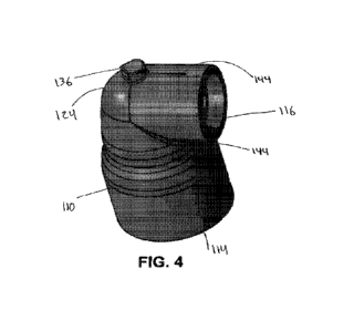
100511 Referring now to FIG. 4, the sprinkler head adapter 100 is shown to
include a
locator lug 136 on the exterior surface of the body 110 adjacent the elbow
124. The
locator lug 136 is shown to protrude orthogonally from the exterior surface of
the body
110, and is further shown to include two sides forming a right angle at the
portion of the
locator lug 136 closest the elbow 124. In some aspects, the locator lug 136
may have
alternative sizes and geometries from that shown in FIG. 4, such as, for
example, a
hexagonal shape as opposed to the three-sided configuration of the locator lug
136 of
FIG. 4,
100521 With reference to FIGS. 5-7, an assembly fixture 146 is shown. The
assembly
fixture 146 is shown to include a cavity 148, with the cavity 148 receiving
the body 110
of the sprinkler head adapter 100 and retain and position of the body 110
during
assembly processes. In some aspects, the assembly fixture 146 can be produced
using
injection molding, as well as other possible production techniques. The
assembly fixture
146 is further shown to include a notch 150, with the notch 150 positioned
within the
cavity 148. The notch 150 is shown to have a geometry complementary to that of
the
locator lug of the body 110 of the sprinkler head adapter 100, and is arranged
such that
the locator lug 136 is received by the notch 150 when the body 110 of the
sprinkler head
adapter 100 is received in the cavity 148 of the assembly fixture 146. The
assembly
fixture 146 is also shown to include a plate 152 and a recess 154, as shown in
FIG. 5.
The plate 152 can to be coupled with the assembly fixture 146 so as to retain
the body
110 of the sprinkler head adapter 100 within the cavity of the assembly
fixture. As
shown, the plate 152 is coupled with a portion of the assembly fixture
adjacent the first
opening 114 of the body 110 when the body 110 of the sprinkler head adapter
100 is
disposed within the cavity 148 of the assembly fixture 146. The arrangement of
the plate
-11-
CA 03143777 2022-1-12
WO 2021/014319
PCT/1112020/056765
152 thereby prevents backout of the body 110 of the sprinkler head adapter 100
from the
cavity 148 of the assembly fixture 146. The recess 154 can opposite the
assembly fixture
146 from the plate 152. The recess 154 is arranged to interface with one or
more
components implemented during manufacturing and/or assembly processes to
facilitate
manipulation and positioning of the assembly fixture. For example, a tool used
in the
manufacture or assembly of the body 110 of the sprinkler head adapter 100 can
interface
with the recess 154 so as to position the assembly fixture 146 for various
operations such
as, for example, ultrasonic welding.
100531 Referring now to FIGS. 6-7, the sprinkler head adapter 100 is shown to
be
received by the cavity 148 of the assembly fixture 146. The locator lug 136 is
shown to
be received by the notch 150 such that the body 110 is maintained in the
orientation
shown in FIGS_ 6-7. As shown in FIG. 6, the plate 152 can adjacent the first
opening
114 of the body 110 such that the sprinkler head adapter 100 is prevented from
moving
longitudinally along the central axis 111. With reference to FIG. 7, the
locator lug 136 is
shown to be positioned within the notch 150 of the assembly fixture 146. The
locator lug
136 includes a right angle formed by two sides thereof, with said right angle
facilitating
the interfacing of the locator lug 136 and the notch 150. Additionally, the
notch 150 is
shown to surround at least a portion of the notch laterally so as to permit
vertical
reception of the sprinkler head adapter 100 into the cavity 148 as well as
removal
therefrom. The positioning of the sprinkler head adapter 100 within the
assembly fixture
146, as shown in FIG. 7, prevents rotational movement of the sprinkler head
adapter 100
in addition to preventing longitudinal movement as shown in FIG. 6. As
described
previously, the locator lug 136 may have various geometries in different
aspects of the
sprinkler head adapter 100, with the geometry of the notch 150 of the assembly
fixture
varying to correspond and facilitating interfacing with the locator lug 136.
100541 The assembly fixture 146 is shown to retain the sprinkler head adapter
100 such
that the cap 112 is directed upward relative to the central axis 111 and in a
vertical
direction substantially opposite the notch 150 relative to the locator lug
136.
Accordingly, such a position can be conducive to manufacture and/or assembly
of the
sprinkler head adapter 100, such as, for example, ultrasonic welding of the
cap 112 to the
body 110. By retaining the sprinkler head adapter 100 or components thereof in
such a
position as shown in FIGS. 6-7, assembly and/or manufacturing processes may be
both
-12-
CA 03143777 2022-1-12
WO 2021/014319
PCT/1112020/056765
expedited and improved for accuracy. By retaining the sprinkler head adapter
100 and/or
the body 110 is the set position as shown, assembly processes such as
ultrasonic welding
may be performed more efficiently and more accurately given a known and set
position
of the components to be assembled.
100551 Referring now to FIGS. 8-9, the body 110 is shown to include
verification
indicators 144. The verification indicators 144 are shown to be disposed on
the exterior
surface of the body 110 between the elbow 124 and the second opening 116
adjacent a
region to which the cap 112 will be coupled. As shown in FIG. 8, the
verification
indicators 144 can to be small lines protruding from the exterior surface of
the body 110.
The verification indicators 144 can, in some aspects, be introduced during
manufacturing
of the body 110. Additionally, the verification indicators 144 are disposed
equidistant
from the second opening 116 of the body 110. With reference to FIG. 9, the
body 110 is
shown to include a plurality of verification indicators 144 about the exterior
surface of
the body 110 disposed between the locator lug 136 and the second opening 116.
In the
example shown in FIG. 9, three verification indicators 144 can
circumferentially about
the exterior surface of the body 110. The three verification indicators 144
are disposed
approximately 120 from one another, and thus establish three points defining
a
geometric plane with said geometric plane extending orthogonally to a central
axis 145,
shown in FIG. 8.
100561 With reference to FIGS. 10-12, the sprinkler head adapter 100 is shown
with the
cap 112 coupled with the body 110. FIGS. 10-11 show the sprinkler head adapter
100 as
properly assembled, which includes the verification indicators 144 directly
adjacent the
portion of the cap 112 positioned nearest the elbow 124 after assembly. Such
positioning
of the verification indicators 144 relative to the cap 112 after assembly
(which may be
performed by, for example, ultrasonic welding) is indicative of a proper
assembly, with
the cap 112 properly coupled with the body 110. It should be noted that, if
any of the
plurality of the verification indicators 144 is not in the proper position
relative to the cap
112, then this can be indicative that the cap 112 and the body 110 are
improperly
assembled. The verification indicators 144 serve to expedite quality
procedures in that
measurement is not needed to determine if the cap 112 has been properly
coupled with
the body 110. The position of the verification indicators 144, if directly
adjacent the cap
112 as shown in FIGS. 10-11, indicates that the cap 112 has been coupled with
the body
-13-
CA 03143777 2022-1-12
WO 2021/014319
PCT/1112020/056765
110 in the proper position and thus assembled a proper sprinkler head adapter
100.
Additionally, the verification indicators 144 serve to prevent any possible
nonconforming sprinkler head adapters 100 from being installed and thus posing
a risk of
malfunction or lack of function.
100571 Contrary to FIGS. 10-11, the example of FIG 12 shows the verification
indicator
144 not directly adjacent the cap 112 after assembly, thus indicating an
improper
assembly. As discussed previously, the body 110 can include a plurality of
verification
indicators 144 disposed about the outer surface of the body 110 between the
elbow 124
and the second opening 116. As shown in FIG. 12, the portion of the cap 112
nearest the
locator lug 136 and the elbow 124 is not positioned directly adjacent the
verification
indicator 144 and thus indicates that the sprinkler head adapter 100 has not
been properly
assembled. With regard to the example of FIG 12, the verification indicators
144 can
such that the assembly of the cap 112 and the body 110 to form the sprinkler
head
adapter 100 can be quickly examined.
1005.81 Referring now to FIGS. 13-17, a sprinkler head adapter 200 is shown.
The
sprinkler head adapter 200 is shown to include a body 210, with the body
having a first
opening 214, a second opening 216, and a third opening 218. The first opening
214 and
the third opening 218 can substantially opposite the sprinkler head adapter
200 one
another and, as shown in FIG. 13, are substantially 1800 apart from one
another. The
body 210 is shown to extend between the first opening 214 and the third
opening 218
and, as shown in FIG. 14, defines a volume 228. The volume 228 extends between
the
first opening 214 and the third opening 218 so as to provide fluid
communication
between the first opening 214 and the third opening 218. Additionally, the
volume 228
provides fluid communication between the first opening 214, the third opening
218 the
second opening 216, which can between the first opening 214 and the third
opening 218
and is disposed on the body 210 substantially equidistant between the first
opening 214
and the third opening 218.
100591 The body 210 is shown to include a locator lug 236 extending from the
exterior
surface of the body 210 between the first opening 214 and the third opening
218, and is
substantially equidistant therebetween. The body 210 can similar to the
sprinkler head
adapter 100 in that the body 210 can to narrow in both interior and exterior
diameter
-14-
CA 03143777 2022-1-12
WO 2021/014319
PCT/1112020/056765
along a central axis 211, with the reduction in diameter between the first
opening 214
and the locator lug 236. Similarly, the body 210 can narrow in both interior
and exterior
diameter between the third opening 218 and the locator lug 236. The reduction
of the
diameter of the body 210 is symmetric about the central axis 211.
Additionally, the body
210 can both between the locator lug 236 and the first opening 214, as well as
between
the locator lug 236 and the third opening 218, to receive a fluid supply line
such as the
fluid supply line 132 as shown and described previously. The body 210 can to
receive a
pair of fluid supply lines 232 in both the first opening 214 and the third
opening 218,
with the fluid supply lines being secured to prevent backout through a variety
of means
including but not limited to glue within the body 210 and/or on a surface of
the fluid
supply lines The body also includes a pair of retention notches 127, which can
be on the
interior surface of the first and third openings of the body 214 and 218,
respectively, and
define an inserted position for the pair of fluid supply lines 232 within the
body 210. In
some aspects, the body may include one or more grooves similar to the groove
of the
sprinkler head adapter 100 so as to define an inserted position for the fluid
supply lines
within the body 210. Additionally, the combination of one or more of the
grooves and,
in some aspects, gaskets, can prevent leakage of any fluid moving from the
fluid supply
lines into the body 210 via the interface between the body 210 and the fluid
supply lines.
100601 Similar to shown and described with regard to the sprinkler head
adapter 100, the
narrowing of the body 210 of the sprinkler head adapter 200 may facilitate
placement of
the sprinkler head adapter 200 in a concealed space 238 as shown in FIG. 15,
as well as
usage with concealed sprinklers such as a sprinkler 234 and one or more fluid
supply
lines 232. It should be noted that the concealed space 238 of FIG. 15 is shown
to be the
same size as the concealed space 138 of FIG. 3. Additionally, the fluid supply
lines 232
as shown in FIG. 15 are shown to be the same as the fluid supply line 132 of
FIG. 3.
However, with regard to the concealed space 238 and the fluid supply lines
232, the
specifications of said components may vary upon application and
implementation, with
specifications of the sprinkler head adapter 200 varying accordingly.
100611 The second opening 216 of the body 210 is disposed between the first
opening
214 and the second opening 216, and is further arranged entirely on a portion
of the body
210 where the diameters of the body 210 have decreased. Similar to the
sprinkler head
adapter 100, the second opening of the sprinkler head adapter 200 can to
interface with
-15-
CA 03143777 2022-1-12
WO 2021/014319
PCT/1112020/056765
the cap 212. The cap 212 may be coupled with the body 210 at the second
opening 216
via a shear joint 230 which may be the same as or similar to the shear joint
130 as shown
and described with reference to the sprinkler head adapter 100, or other the
coupling may
include other possible coupling means including those described with reference
to FIGS.
1-12. The body 210 is also shown to include a gasket 222 and groove 223 the
same or
similar to the gasket 122 and the groove 123 of the sprinkler head adapter
100, with the
groove receiving and retaining the gasket 122. The gasket 222 can to prevent
any
leakage of fluid traveling from the body 210 to the cap 212. In some aspects,
the cap
may include a coupling means (e.g., threading, adhesive, boding agent,
mechanical
structure, etc.) to facilitate coupling to a sprinkler. The sprinkler 234
coupled with the
cap 212 may be the same as or similar to the sprinkler 134 as shown in FIG. 3.
The
coupling of the sprinkler 234 to the sprinkler head adapter 200 permits the
flow of fluid
from the pair of fluid supply lines 232 (coupled with the body 210 at the
first opening
214 and/or the third opening 218) to the sprinkler 234, which is facilitated
by fluid
communication permitting the flow of fluid through the body 210, through the
second
opening 216 and the cap 212, and to the sprinkler 234 so as to provide fire
protection
and/or suppression for an area.
[0062] With reference to FIG. 15, the body 210 of the sprinkler head adapter
200
receives the pair of fluid supply lines 232 in the first opening 214 and the
third opening
218 such that the pair of fluid supply lines 232 can at least partially within
the volume
228 of the body 210. As shown, the sprinkler 234 is coupled with the cap 212
within the
concealed space 238 such that only a portion of the sprinkler extends through
a piece of
drywall 240, although in some aspects the concealed space 238 may be otherwise
confined and defined. As shown in the example of FIG. 15, the pair of fluid
supply lines
232 are 1-inch pipe, which is commonly found to be too large when serving as
fluid
supply for concealed sprinklers in small areas such as the concealed space
238. As
shown and described previously, and similar to the configuration of the
sprinkler head
adapter 100, the narrowing of the diameter of the body 210 accommodates the
cap 212
and, ultimately, the sprinkler 234 and the pair of fluid supply lines 232
within the
concealed space 238.
[0063] Referring now to FIGS. 16-17, the body 210 of the sprinkler head
adapter 200 is
shown to include verification indicators 244. As shown in FIGS. 13-15, the
verification
-16-
CA 03143777 2022-1-12
WO 2021/014319
PCT/1112020/056765
indicators can on an exterior surface of the body 210 between the locator lug
and the
second opening 216, and can such that the verification indicators 244 define a
vertical
plane. As shown in FIG. 16, the verification indicators 244 are disposed
circumferentially about the body 210 adjacent the second opening 216
substantially 1200
apart from one another. Such spacing facilitates the formation of the vertical
plane, as
previously shown and described with respect to the verification indicators 144
of the
sprinkler head adapter 100. Additionally, in some aspects the body 210 of the
sprinlder
head adapter 200 may include multiple lug locators 236, as shown in FIG. 16.
The
locator lugs 236 may be used to position and retain the body 210 within an
assembly
fixture such as assembly fixture 246 in order to perform manufacturing and/or
assembly
operations. For example, the cap 212 may be coupled with the body 210 via
ultrasonic
welding or other processes while the body 210 is retained within the fixture
plate, the
fixture plate have a cavity and notch with geometry corresponding to that of
the body
210.
100641 Referring now to FIGS. 18-20, an assembly fixture 246 is shown. The
assembly
fixture 246 can to receive and retain the sprinkler head adapter 200, as shown
in FIGS.
19-20 As shown in FIG. 18, the assembly fixture includes a cavity 248, with
the cavity
248 receiving the sprinkler head adapter 200. The cavity 248 can have various
geometries, with the various geometries corresponding to the geometry of the
sprinkler
head adapter 200 such that the cavity receives and subsequently retains the
sprinkler
head adapter 200. The assembly fixture 246 may be implemented similarly to the
assembly fixture 146 as shown and described previously. That is to say that
the
assembly fixture 246 may be implemented in manufacturing and/or assembly
processes
(for example, ultrasonic welding) so as to retain the sprinkler head adapter
200 and any
components thereof in a predetermined position. The geometry of the cavity 248
facilitates said retention, as the geometry can to complement the geometry of
the
sprinkler head adapter 200.
100651 The assembly fixture 246 is shown to include a pair of notches 250,
which may
be the same as and/or similar to the notch 150 of the assembly fixture 146 as
shown and
described previously. The notches 250 can in opposite sidewalls of the
assembly fixture
146, and can have a complementary geometry to the one or more locator lugs 236
disposed on the exterior surface of the body 210 of the sprinkler head adapter
200. As
-17-
CA 03143777 2022-1-12
WO 2021/014319
PCT/1112020/056765
shown, the notches 150 include a right angle, which corresponds to a right
angle found
on the locator lugs 236 of the sprinkler head adapter 200. However, in some
aspects the
locator lugs 236 may have alternate geometries and, accordingly, the notches
150 may
have complementary geometries such that the notches 150 can to at least
partially receive
the locator lugs 236 as the sprinkler head adapter 200 is received in the
cavity 248 of the
assembly fixture 246. With reference to FIGS_ 19-20, the assembly fixture 246
is shown
to prevent movement of the sprinkler head adapter 200 while the sprinkler head
adapter
200 is at least partially received by the cavity 248. In the example of FIG.
19, the locator
lugs 236 can at least partially within the notches 150 and, as facilitated by
the structure
of the notches 150, the sprinkler head adapter 200 is retained within the
cavity 248 such
that movement along the central axis 211 is prevented. With reference to the
example of
FIG. 20, the sprinkler head adapter 200 can within the cavity 248 of the
assembly fixture
146 as in the example of FIG. 19. As shown in FIG. 20, the assembly fixture
246 (in
conjunction with the notches 150 thereof) prevents rotational movement of the
sprinkler
head adapter 200. The retention of the sprinkler head adapter 200 by the
assembly
fixture 246, as shown and described with reference to FIGS. 18-20, facilitates
assembly
and/or manufacturing procedures for the sprinkler head adapter. In retaining
the
sprinkler head adapter 200 and components thereof in a predetermined and
desired
position for such procedures, efficiency and quality of products is increased
and error is
decreased due to the known and constant positioning of the necessary
components.
[00661 FIGS. 21-22 show the verification indicators 244 in relation to the cap
212 after
the body 210 and the cap 212 have been assembled. The verification indicators
244 can
similar to or the same as the verification indicators 144 of the sprinkler
head adapter 100,
and similarly indicate proper assembly or lack thereof between the body 210
and the cap
212. FIG. 21 shows the verification indicator 244 directly adjacent the cap
212, which is
indicative of a proper assembly and allows for quick and efficient
verification of a proper
assembly. Conversely, FIG. 22 shows the verification indicator 244 not
directly adjacent
the cap 212 (e.g., a gap is observable), which is indicative of an improper
assembly and
allows for quick and efficient identification of a proper assembly. The
identification of
an improper assembly, which may result in malfunction or a lack of function,
is critical
and is observable by the position of the cap 212 relative to the verification
indicators
244, similar to those of the sprinkler head adapter 100.
-18-
CA 03143777 2022-1-12
WO 2021/014319
PCT/1112020/056765
100671 Referring now to FIGS. 23-26, a sprinkler head adapter 300 is shown.
The
sprinkler head adapter is shown to include a body 310 and a cap 312. The body
310 is
shown to be of an elongated cylindrical geometry symmetrically about a central
axis 311,
and is shown to include a first opening 314 and a second opening 316 at
opposite ends of
the body 310. The cap 112 is shown to be coupled with the body 310, where a
shear
joint 330 is formed at the interface of the second opening 316 of the body 310
and the
cap 312. Additionally, the cap 312 may include one or more textures or other
geometry
on exterior surfaces thereof so as to facilitate gripping and/or manipulation
of the cap
312 by a user and/or tool. The cap 312 is coupled with the body 310 so as to
assemble
the sprinkler head adapter 300 using ultrasonic welding, although other
techniques and
processes may be implemented in some aspects.
[00681 The body 310 is shown to define a volume 328 having a substantially
cylindrical
geometry and centered about the central axis 311. The body 310 includes a
circumferential groove 326 arranged adjacent the interior surface of the body
between
the first opening 314 and the second opening 316. In some aspects, a gasket
can be at
least partially within the circumferential groove 326 so as to prevent leakage
upon
coupling of the body 310 to a fluid supply line 332 and subsequent flow of
fluid from the
fluid supply line 332 and into the volume 328 The sprinkler head adapter 300
is shown
to include a gasket 322 disposed within a gasket notch 323, with the gasket
322 and the
gasket notch 323 adjacent the interface between the second opening 316 of the
body 310
and the cap 312. The gasket 322 can within the gasket notch 323, with the
gasket notch
323 spanning the circumference of the volume adjacent the shear joint 330. The
gasket
322 is positioned between the second opening 316 of the body 310 and the cap
312 so as
to prevent leakage of any fluid flowing from the fluid supply line 332 into
the volume
328 of the body 310 and subsequently past the interface of the body 310 and
the cap 312
to ultimately reach a sprinkler 334. In some aspects, the sprinkler 334 may be
the same
as or similar to the sprinkler 134 as shown and described previously. The cap
312 is
shown to include a threading 318 to facilitate coupling with the sprinkler
334, which may
be a %-inch NPT fire protection sprinlder, for example. The sprinkler 334 can
to have
complimentary geometry to the cap 312 (e.g., threads) so as to facilitate
coupling
between the cap 312 of the sprinkler head adapter 300 and the sprinkler 334.
In some
aspects, the coupling between the cap 312 and the sprinkler 334 may include
alternative
-19-
CA 03143777 2022-1-12
WO 2021/014319
PCT/1112020/056765
coupling mechanisms including various complementary geometries, and may also
implement glue, adhesive, or other bonding agents_
100691 In many buildings, it is common for 1-inch diameter pipe to be
installed for fluid
supply lines (such as fluid supply line 332) to provide water or other fire
suppression
fluid to a system of one or more sprinklers (such as the sprinkler 334) in
order to provide
fire protection and/or suppression for an area. However, fittings and adapters
for 1-inch
pipe are bulky and often require a substantial amount of space in order to be
installed and
facilitate the flow of fluid from the 1-inch fluid supply line to the
sprinkler. As such, the
use of 1-inch pipes for fluid supply lines can present challenges in
restricted areas, such
as the concealed space 138 as shown and described previously. To combat the
issue of
bulky 1-inch pipe fittings and adapters in small spaces, 1-inch pipes (which
are standard
and commonly installed in many buildings) are transitioned to %-inch pipes to
serve as
fluid supply lines such as the fluid supply line 332 in contact with either a
sprinkler head
adapter (such as the sprinkler head adapter 300) or the sprinkler itself. Such
a transition
requires additional and often expensive hardware to transition the 1-inch
pipes to 3/4-inch
pipes, and the subsequently fit the 3/4-inch pipes to the sprinkler.
Additionally, the
reduction in pipe size from 1-inch to 3/4-inch reduces potential volumetric
flow rates to
the sprinklers and can subsequently reduce fire protection/suppression
potential. This
creates a need for additional sprinkler and fluid supply line installation,
which is costly.
100701 The sprinkler head adapter 300 can to accommodate both pipes having a 1-
inch
diameter and pipes having a 3/4-inch diameter as the fluid supply lines 332.
More
specifically the body 310 of the sprinkler head adapter 300 can be coupled
with both 1-
inch diameter and 3/4-inch diameter pipes. With reference to FIG. 25, the
fluid supply
line 332 is shown to be a 1-inch diameter pipe. As shown, the body of the
sprinkler head
adapter 300 (beginning with the portion adjacent the first opening 314) is
shown to be
received by and into the fluid supply line 332 so as to couple to the fluid
supply line 332.
That is to say that, in the example of FIG 20, the sprinkler head adapter 300
functions as
a male spigot, which may be inserted in various 1-inch pipes such as an elbow,
tee,
bushing, or other pipe or fluid supply line configurations. The exterior
surface of the
body 310 of the sprinkler head adapter 300 is shown to contact the interior
surface of the
fluid supply line 332 so as to facilitate sealing and provide fluid
communication between
the fluid supply line 332 and the volume 328 of the body 310 of the sprinkler
head
-20-
CA 03143777 2022-1-12
WO 2021/014319
PCT/1112020/056765
adapter 300. The sprinkler head adapter 300 is also coupled, via the cap 312,
to the
sprinkler 334. Accordingly, the sprinkler head adapter 300 facilitates fluid
communication between the fluid supply line 332 and the sprinkler 334. By
coupling the
1-inch pipe serving as the fluid supply line 332, the 1-inch pipe can provide
fluid directly
to the sprinkler 334 without transitioning to a pipe of a smaller diameter and
thus
decreasing volumetric flow potential as well as increasing possible costs for
additional
fixtures, adapters, and sprinklers to provide fire protection/suppression for
a given space.
100711 With reference to FIG. 26, the sprinkler head adapter 300 is shown to
receive the
fluid supply line 332 within the volume 328 of the body 310. It should be
noted that the
sprinkler head adapter 300 shown in FIGS. 20-21 can be the same sprinkler head
adapter
300 interfacing with two different sizes of pipe used as the fluid supply line
332 In the
example of FIG. 26, the fluid supply line 332 is shown to be a 314-inch pipe
with the
sprinkler head adapter 300 serving as a female socket to accept the 3/4-inch
pipe. The
example of FIG. 26 is also shown to include a gasket 321, which can adjacent
the fluid
supply line 332 and may be implemented in some aspects to facilitate the
formation of a
seal between the fluid supply line 332 and the body 310 such that fluid
communication
may be provided between the fluid supply line 332, the sprinkler head adapter
300, and
subsequently the sprinkler 334 shown to be coupled with the cap 312 of the
sprinkler
head adapter 300. The body 310 is shown to be coupled with the cap 312
adjacent the
shear joint 330 (with the assembly of the cap 312 and the body 310 formed
using
ultrasonic welding, according to some aspects). The gasket 322 is shown to be
positioned within the gasket notch 323 such that the gasket 322 is retained
within the
sprinkler head adapter 300 and facilitates the formation of a seal between the
body 310
and the cap 312 such that fluid communication is provided through the
sprinkler head
adapter 300 and to the sprinkler 334 such that fluid flowing via said fluid
communication
may be dispersed to an area to provide fire protection/suppression.
100721 The sprinkler head adapter 300 may be manufactured and assembled
according to
a variety of means and/or methods. For example, the body 310 and the cap 312
may be
produced using injection molding processes and techniques and may be comprised
of
PVC or CPVC materials. Assembly of the body 310 and the cap 312 to form the
sprinkler head adapter 300 may be done using, for example, ultrasonic welding,
although
-21-
CA 03143777 2022-1-12
WO 2021/014319
PCT/1112020/056765
other assembly processes may also be implemented. One or both of the gaskets
321 and
322 may be a polyurethane material, or may also be comprised of other
materials.
100731 As utilized herein, the terms "approximately," "about,"
"substantially", and
similar terms are intended to include any given ranges or numbers -F1-10%.
These terms
include insubstantial or inconsequential modifications or alterations of the
subject matter
described and claimed are considered to be within the scope of the disclosure
as recited
in the appended claims.
100741 It should be noted that the term "exemplary" and variations thereof, as
used
herein to describe various embodiments, are intended to indicate that such
embodiments
are possible examples, representations, or illustrations of possible
embodiments (and
such terms are not intended to connote that such embodiments are necessarily
extraordinary or superlative examples).
100751 The term "coupled" and variations thereof, as used herein, means the
joining of
two members directly or indirectly to one another. Such joining may be
stationary (e.g.,
permanent or fixed) or moveable (e.g., removable or releasable). Such joining
may be
achieved with the two members coupled directly to each other, with the two
members
coupled with each other using a separate intervening member and any additional
intermediate members coupled with one another, or with the two members coupled
with
each other using an intervening member that is integrally formed as a single
unitary body
with one of the two members. If "coupled" or variations thereof are modified
by an
additional term (e.g., directly coupled), the generic definition of "coupled"
provided
above is modified by the plain language meaning of the additional term (e.g.,
"directly
coupled" means the joining of two members without any separate intervening
member),
resulting in a narrower definition than the generic definition of "coupled"
provided
above. Such coupling may be mechanical, electrical, or fluidic.
100761 The term "or," as used herein, is used in its inclusive sense (and not
in its
exclusive sense) so that when used to connect a list of elements, the term
"or" means
one, some, or all of the elements in the list. Conjunctive language such as
the phrase "at
least one of X, Y, and Z," unless specifically stated otherwise, is understood
to convey
that an element may be either X, Y, Z; X and Y; X and Z; Y and Z; or X, Y, and
Z (i.e.,
-22-
CA 03143777 2022-1-12
WO 2021/014319
PCT/1112020/056765
any combination of X, Y, and Z). Thus, such conjunctive language is not
generally
intended to imply that certain embodiments require at least one of X, at least
one of Y,
and at least one of Z to each be present, unless otherwise indicated.
[00771 References herein to the positions of elements (e.g., "top," "bottom,"
"above,"
"below") are merely used to describe the orientation of various elements in
the
FIGURES. It should be noted that the orientation of various elements may
differ
according to other exemplary embodiments, and that such variations are
intended to be
encompassed by the present disclosure.
[00781 The construction and arrangement of the fitting assembly as shown in
the various
exemplary embodiments is illustrative only. Additionally, any element
disclosed in one
embodiment may be incorporated or utilized with any other embodiment disclosed
herein. Although only one example of an element from one embodiment that can
be
incorporated or utilized in another embodiment has been described above, it
should be
appreciated that other elements of the various embodiments may be incorporated
or
utilized with any of the other embodiments disclosed herein.
-23-
CA 03143777 2022-1-12