Note: Descriptions are shown in the official language in which they were submitted.
ACETABULAR BALL IMPACTOR ASSEMBLY
BACKGROUND OF THE INVENTION
Field of the Invention
[0001] The present invention relates to surgical instruments used in
connection
with implanting a reverse hip prosthesis in a patient. More particularly, the
invention has to do
with impactors for implanting an acetabular cup, an acetabular ball and a
femoral cup.
The Related Art
[0002] A reverse hip prosthesis is described in U.S. Patents Nos.
8,313,531 B2
and 8,540,779 82. The prosthesis and a revision surgery method also are
described in U.S.
Patent No. 8,992,627 B2.
SUMMARY OF THE INVENTION
[0003] As described in the patents referenced above, the acetabular
cup is affixed
in the acetabulum by impacting it therein and then, if needed, affixing it
further using screws.
The acetabular ball is affixed by means of a Morse taper to a stem extending
from the bottom of
the concave surface of the acetabular cup and the femoral cup is affixed to
the femoral implant
(or femoral stem) by means of a Morse Taper. The surgical instruments of the
invention,
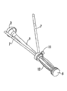
sometimes referred to herein as surgical tools, enable a surgeon to impact
each of these
components of the prosthesis with optimal placement of the acetabular cup and
secure
affixation of the acetabular ball and the femoral cup.
1
Date Recue/Date Received 2022-07-11
BRIEF DESCRIPTION OF THE DRAWINGS
[0004] Fig. 1 is a perspective view of the acetabular cup impactor
assembly of the invention.
[0005] Fig. 2 is an elevation view of the acetabular cup impactor
assembly.
[0006] Fig. 3 is a section view of Fig. 2 illustrating a partial
acetabular
bone element.
[0007] Fig. 4 is an exploded view of the acetabular cup impactor
assembly.
[0008] Fig. 5 is an elevation view of an acetabular cup handle for the
acetabular cup impactor assembly.
[0009] Fig. 6 is an elevation view of an inner shaft for the acetabular
cup impactor assembly.
[0010] Fig. 7 is an elevation view of an inclination-anteversion
guide rod
for the acetabular cup impactor assembly.
[0011] Fig. 8 is an elevation view of a collet for the acetabular cup
impactor assembly.
[0012] Fig. 9 is an elevation view of a universal handle for the
acetabular ball impactor assembly and the femoral cup impactor assembly.
[0013] Fig. 10 is a perspective view of an acetabular ball impactor
assembly, acetabular ball and acetabular cup.
[0014] Fig. 11 is an elevation view of Fig. 10.
2
Date repel date received 2021-12-23
[0015] Fig. 12 is a section view of Fig. 11 with an added acetabular
bone element.
[0016] Fig. 13 is an elevation view of an acetabular ball impactor.
[0017] Fig. 13A is a section view of the acetabular ball impactor of Fig.
13.
[0018] Fig. 14 is an elevation view of a femoral cup impactor assembly,
[0019] Fig. 15 is a perspective view of a femoral cup impactor.
[0020] Fig. 16 is a side elevation view of Fig. 15.
[0021] Fig. 17 is a top elevation view of Fig. 16.
[0022] Fig. 18 is a bottom elevation view of Fig. 16.
[0023] Fig. 19 is an elevation view of a femoral cup impactor assembly
and a femoral cup positioned in a femoral implant, the femoral implant being
illustrated in section.
[0024] Fig. 20 is a section view of Fig. 19.
DESCRIPTION OF THE PREFERRED EMBODIMENTS
[0025] The impactors of the present invention are used to implant in a
patient three elements of a reverse hip prosthesis. The elements are the
acetabular cup, the acetabular ball and the femoral cup.
[0026] Following preparation of the acetabulum to receive the
acetabular cup, the acetabular cup is positioned in the acetabulum and
impacted
therein using the acetabular cup impactor assembly 1 illustrated in Figs. 1-4.
Elements of acetabular cup impactor assembly 1 are illustrated in Figs. 5-8.
3
Date recue/ date received 2021-12-23
Figs. 1-3 illustrate acetabular cup 2 in relation to the assembly 1 and Fig. 3
includes a portion of the acetabulum 3.
[0027] The acetabular cup impactor assembly 1 is comprised of
acetabular cup handle 4, having a channel extending annularly along the length
thereof, the channel being open at the proximal and distal ends of the handle
4,
inner shaft 5 having a knob 6 at the proximal end thereof, inclination-
anteversion
guide rods 7 and collet 8. Guide rods 7 are threaded at their distal ends. The
acetabular cup handle 4 has a handle shaft 9 and an inclination-anteversion
guide collar 10 rotatably mounted on handle shaft 9. lnclination-anteversion
guide collar 10, sometimes referred to herein as rotatable guide 10, has
threaded
holes (See Fig. 4.) designated as anteversion holes 15 and inclination hole
16. A
rod 7 is threaded into hole 16 and one of holes 15, depending on whether the
right or left hip is being replaced. Thumb screw 11 is tightened to prevent
rotation of guide collar 10 when a rod 7 is optimally positioned during
surgery.
Handle element 12 is affixed proximally on shaft 9 and sleeve 13 is affixed to
the
distal end of shaft 9. The sleeve 13 has a tapered annular inner portion, the
taper narrowing in the proximal direction, the tapered annular inner portion
of the
sleeve 13 being sized to cause a distal end of the collet 8 to contract when
the
collet 8 moves into the sleeve 13 in a proximal direction. Fig. 4 illustrates
three
collets 8, each being of a different size for different sizes of acetabular
cups 2.
Acetabular cup 2 has a stem 14 projecting from the bottom of the concave
surface thereof. The size of the collet 8 refers to an annular inner portion
thereof
which is sized to releasably grip a proximal portion of the stem 14. The
collet 8
4
Date recue/ date received 2021-12-23
grips the stem 14 when the collet 8 is contracted and releases the stem 14
when
the collet 8 is open, Le., not contracted.
[0028] In the surgical method of the invention, the acetabulum 3 is
prepared to receive an appropriately sized acetabular cup 2 and a collet 8
sized
for the cup is selected. Inner shaft 5 is inserted into the distal end of
acetabular
cup handle 4 and the collet 8 is then attached to the distal end of inner
shaft 5.
The collet 8 is then pushed over the stem 14 of acetabular cup 2 and the
collet 8
is pulled into sleeve 13 so that the collet 8 firmly grips the stem 14. This
causes
shaft 5 to move proximally leaving a space between knob 6 and the proximal end
of handle element 12. An inclination-anteversion guide rod 7 is threaded into
hole 16 of inclination-anteversion guide collar 10, another inclination-
anteversion
guide rod 7 is threaded into a hole 15 (see Fig. 4), and the acetabular cup 2
is
placed in acetabulum 3. Then the screw holes in cup 2 are aligned properly in
the acetabulum for eventual fixation of the cup to the acetabulum using
screws.
The inclination-anteversion guide collar 10 is then rotated until the rods 7
are
properly positioned and thumb screw 11 then is tightened. It should be noted
that the guide rods are set at a 45 degree angle relative to the shaft 9 and
at a 20
degree angle relative to one another. The surgeon sets the inclination using
the
rod threaded into hole 16 by keeping the rod parallel to the floor and
pointing it
toward the shoulder of the patient. If a left hip is being replaced it is
pointed at
the left shoulder and if a right hip is being replaced it is pointed at the
right
shoulder. When the inclination is set, the surgeon then sets the anteversion
using the rod 7 threaded into a hole 15. Either hole 15 is used, depending on
Date recue/ date received 2021-12-23
whether the right hip or left hip is being replaced as will be apparent to
those
having ordinary skill in the art based on the disclosures herein. The
anteversion
rod creates 20 degrees of anteversion with the inclination rod by orienting
the
anteversion rod toward the same shoulder. The rods are used in this manner
with a posterior surgical approach and this properly sets the orientation of
the
cup 2 at a compound angle of 45 degrees of inclination and 20 degrees of
anteversion. The assembly is maintained in position by holding handle element
12 as the proximal end of knob 6 is struck with a hammer thereby impacting the
acetabular cup in the acetabulum. Assembly 1 is then removed from the
operating site.
[0029] An acetabular ball impactor assembly is illustrated in Figs 10-12
and the acetabular ball impactor 20 is illustrated in elevation in Fig. 13.
The
acetabular ball impactor assembly 13 is comprised of acetabular ball impactor
20
and universal handle 40. (See also Fig. 9). The universal handle 40 is
comprised of shaft 41 having a threaded portion 42 at its distal end and a
handle
element 43 at its proximal end. The acetabular ball impactor 20 has a proximal
end and a distal end. As illustrated in Fig. 13A, the proximal end of
acetabular
ball impactor 20 has threads 22 and the distal end has a concave surface
portion
23. The concave surface portion being in the shape of a section of a sphere.
The threaded portion 42 is threaded into the threads 22 of the acetabular ball
impactor 20.
[0030] Acetabular ball impactor 20 is made in sizes compatible with
differently sized acetabular balls 21. When a ball 21 is selected, it is
placed over
6
Date recue/ date received 2021-12-23
stem 14 of acetabular cup 2. The appropriately sized acetabular ball impactor
20
is threaded onto the universal handle 40 and the concave surface of acetabular
ball impactor 20 is placed over the ball, allowing the ball to be received
therein.
Appropriate sizing in this context means the concave surface portion of the
acetabular ball impactor is sized to receive the acetabular ball. Thus the
concave surface has the shape of a section of a sphere and a size the same as
or approximately the same as the spherical size of the acetabular ball to be
received therein. With the universal handle 40 held in a position wherein the
central axis of the stem 14 and the central axis of the shaft 41 are in the
same or
approximately the same line (as illustrated in Figs. 11 and 12) the proximal
end
of handle element 43 is struck with a hammer to cause the acetabular ball 21
to
be firmly affixed to stem 14 by means of the Morse taper.
[0031] A femoral cup impactor 30 is illustrated in Figs. 15-18. It is
comprised of a convex surface portion, referred to herein as impactor tip 31,
at its
distal end and a threaded portion 32 at its proximal end. The convex surface
portion is in the shape of a sphere. Threaded portion 32 is used to affix the
impactor to universal handle 40. When the femoral cup impactor 30 is affixed
to
universal handle 40, the combination of elements is referred to herein as a
femoral cup impactor assembly.
[0032] Figs. 19 and 20 further illustrate the femoral cup impactor, a
femoral cup 50 and a femoral implant 51. The femoral cup 50 has a stem 52
which is sized to fit in a Morse taper relationship in recess 53 of femoral
stem 51.
7
Date recue/ date received 2021-12-23
[0033] Femoral cup impactor 30 is made in sizes compatible with
differently sized femoral cups 50. The femoral cup 50 has a concave surface
portion in the shape of a section of a sphere sized to articulate on
acetabular ball
21. When a femoral cup 50 is selected, the stem 52 is placed in recess 53. The
appropriately sized acetabular cup impactor is threaded onto the universal
handle 40 and the convex impactor tip 31 is placed into the concave portion of
femoral cup 50. Appropriate sizing in this context means the convex surface of
the femoral cup impactor is sized to be received in the concave surface
portion of
the femoral cup. Thus the convex surface has the shape of a section of a
sphere
and a size the same as or approximately the same as the concave surface
portion of the femoral cup. Thus the convex surface has the shape of a section
of a sphere and a size the same as or approximately the same as the concave
surface portion of the femoral cup. With the universal handle 40 held in a
position wherein the central axis of the stem 52 and the central axis of the
shaft
41 are in the same or approximately the same line (as illustrated in Figs. 19
and
20) the proximal end of handle element 43 is struck with a hammer to cause the
femoral cup 50 to be firmly affixed to femoral implant 51 by means of the
Morse
taper.
[0034] The surgical instruments of the invention may comprise a portion
of surgical kits. The kits may contain one or more than one of the surgical
instruments of the invention along with other surgical instruments and/or
implants.
8
Date recue/ date received 2021-12-23