Language selection

Search

Patent 3143877 Summary

Third-party information liability

Some of the information on this Web page has been provided by external sources. The Government of Canada is not responsible for the accuracy, reliability or currency of the information supplied by external sources. Users wishing to rely upon this information should consult directly with the source of the information. Content provided by external sources is not subject to official languages, privacy and accessibility requirements.

Claims and Abstract availability

Any discrepancies in the text and image of the Claims and Abstract are due to differing posting times. Text of the Claims and Abstract are posted:

  • At the time the application is open to public inspection;
  • At the time of issue of the patent (grant).
(12) Patent Application: (11) CA 3143877
(54) English Title: CABLE SWITCH WITH USB CHARGER
(54) French Title: INTERRUPTEUR DE CABLE A CHARGEUR USB
Status: Compliant
Bibliographic Data
(51) International Patent Classification (IPC):
  • H01H 9/02 (2006.01)
  • F21V 23/04 (2006.01)
  • H01H 13/00 (2006.01)
  • H01H 23/00 (2006.01)
  • H01H 23/04 (2006.01)
  • H01R 25/00 (2006.01)
(72) Inventors :
  • ROGOWIEC, BARTOSZ ZYGMUNT (Spain)
(73) Owners :
  • ROGOWIEC, BARTOSZ ZYGMUNT (Spain)
(71) Applicants :
  • ROGOWIEC, BARTOSZ ZYGMUNT (Spain)
(74) Agent: MCMILLAN LLP
(74) Associate agent:
(45) Issued:
(86) PCT Filing Date: 2020-06-22
(87) Open to Public Inspection: 2020-12-24
Availability of licence: N/A
(25) Language of filing: English

Patent Cooperation Treaty (PCT): Yes
(86) PCT Filing Number: PCT/ES2020/070408
(87) International Publication Number: WO2020/254712
(85) National Entry: 2021-12-16

(30) Application Priority Data:
Application No. Country/Territory Date
U201931053 Spain 2019-06-21

Abstracts

English Abstract

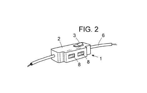
The invention relates to a cable switch with a USB charger, which is formed from: a protective case (2) containing electricity-interrupting means (3) connected between an input connector (4) and an output connector (5), said connectors being connected to the live wire (F) and the neutral wire (N) of the electric cable (6) in which the switch is installed; a power supply (7) connected between the input connector (4) and the output connector (5); and at least one USB connection port (8) connected to the power supply (7). Preferably, the switch comprises an EMI filter (9) connected between the input connector (4) and the power supply (7). Preferably, the power supply (7) is a power source that converts 110-220 V alternating current into 5V/2A continuous current.


French Abstract

L'invention concerne un interrupteur de câble à chargeur USB qui est constitué à partir d'un boîtier (2) de protection à l'intérieur duquel est logé un moyen d'interruption d'électricité (3) connecté entre un connecteur d'entrée (4) et un connecteur de sortie (5) lesquels sont connectés aux fils de phase (F) et neutre (N) du câble (6) électrique dans lequel ledit interrupteur est installé, et une source d'alimentation (7) connectée entre le connecteur d'entrée (4) et le connecteur de sortie (5) et, au moins, un port de connexion USB (8) connecté à ladite source d'alimentation (7). De préférence, l'interrupteur comprend un filtre EMI (9) connecté entre le connecteur d'entrée (4) et la source d'alimentation (7). De préférence, la source d'alimentation (7) est une source de puissance qui convertit le courant alternatif 110-220V en courant continu 5V2A.

Claims

Note: Claims are shown in the official language in which they were submitted.


1
CLAIMS
1. Cable switch with USB charger that, constituted from a protective casing
(2) inside of
which some means of switching electricity on and off are housed (3), connected
between
an input connector (4) and an output connector (5) which, in turn, are
connected to the
phase (F) and neutral (N) wires of the electrical cable (6) in which said
switch is installed,
is characterized by also comprising, also housed inside said casing (2), a
power supply
(7) connected between the input connector (4) and the output connector (5)
and, at least,
one USB connection port (8) connected to said power supply (7).
2. Cable switch with USB charger, according to claim 1, characterized by
further
comprising an EMI filter (9) connected between the input connector (4) and the
power
supply (7).
3. Cable switch with USB charger, according to claim 1 or 2, characterized in
that the
housing (2) includes two, three or more USB connectors (8) connected in
parallel to the
power supply (7).
4. Cable switch with USB charger, according to any of claims 1 or 3,
characterized in
that the USB connector or connectors (8) is/are female connection ports.
5. Cable switch with USB charger, according to any of claims 1 to 3,
characterized in
that the power source (7) is a power source that converts 110-220V alternating
current
into 5V2A direct current.

Description

Note: Descriptions are shown in the official language in which they were submitted.


CA 03143877 2021-12-16
1
CABLE SWITCH WITH USB CHARGER
SPECIFICATION
SUBJECT MATTER OF THE INVENTION
The invention, as expressed in the wording of this specification, refers to a
cable switch
with a USB charger that provides, for its intended function, advantages and
characteristics, which are described in detail below.
The subject matter of this invention is an electrical switch that, in addition
to the
conventional components that allow the opening or closing the pathway of
electrical
current through the cable in which they are installed, to turn a device on or
off, for example
a lamp. It comprises a series of additional electronic components, including
at least one
USB connector, that makes it possible, by connecting the corresponding USB
cable, to
charge the battery of an electronic device such as, for example, a mobile
phone, electronic
tablet, laptop or similar.
FIELD OF APPLICATION OF THE INVENTION
The field of application of this invention is framed within the sector of the
industry
dedicated to the manufacture of electrical accessories, focusing particularly
on the field
of switch mechanisms, while also covering the field of battery chargers for
electronic
devices by USB connection.
BACKGROUND OF THE INVENTION
As is known, most portable electronic devices have a battery that must be
recharged
periodically by connecting to the network through a suitable device.
In most current devices, said device is a USB charger, consisting of a plug
socket that, in
addition to the corresponding electronic components, has a female USB
connector to
which the male USB connector of a cable is connected, the opposite end of
which has
another connector to connect to the device.
Date recue / Date received 2021-12-16

CA 03143877 2021-12-16
2
The problem is, on the one hand, that these chargers are normally only
designed to
provide this function and, on the other hand, that when they are plugged in,
they occupy
a network socket connection preventing it from being used for other purposes,
which can
lead to a nuisance, given the growing use of electrical appliances in homes
and the limited
network sockets they have.
The purpose of this invention is to provide a means to take advantage of the
pathway of
electric current in a common electrical accessory, such as a switch, and to
combine both,
avoiding inconveniences, in such a way that, in addition to serving to charge
the battery
of an electronic device, it also has another function, namely, to take
advantage of an
electrical accessory with a specific function, such as that of a switch, while
also allowing
the battery of an electronic device to be charged and, at the same time, to
avoid occupying
an additional network socket.
On the other hand, and as a reference to the current state of the art, it
should be noted
that the existence of any other cable switch with USB charger, or any other
similar
invention that presents technical characteristics that are equal or similar to
those by the
one claimed herein is unknown, at least to the applicant.
It should be noted that the initials USB refer to Universal Series Bus, which
is a
communications bus in compliance with a standard that defines cables,
connectors and
protocols in a bus in order to connect, communicate and provide electrical
power between
computers, peripherals and electronic devices.
DESCRIPTION OF THE INVENTION
The cable switch with USB charger that the invention proposes constitutes an
optimal
solution to the aforementioned technical problem, the characterizing details
that
distinguish it being conveniently collected in the final claims that accompany
this
description.
Specifically, what the invention proposes, as noted above, is an electrical
cable switch
(both table and floor) that, in addition to the conventional components that
allow its
function to open or close the pathway of electrical current through the cable
in which it is
Date recue / Date received 2021-12-16

CA 03143877 2021-12-16
3
installed, to turn on or off an electrical appliance, for example a lamp, it
also includes a
series of additional electronic components and, at least, one USB connector
that makes
it possible, by connecting a corresponding USB cable, to charge the battery of
an
electronic device such as for example a mobile phone, electronic tablet,
laptop or the like.
For this reason, and more specifically, the switch of the invention, formed in
a known way
from a protective casing which houses a means of interrupting the electricity,
such as a
mechanical pushbutton, a mechanical or proximity dimmer (potentiometer ), a
tactile
switch, or a proximity switch, connected between an input connector and an
output
connector that, respectively, are connected to the phase and neutral cables,
is
distinguished by comprising, a power supply connected between said input and
output
connectors and at least one USB connection port connected to said power
supply.
Preferably, furthermore, the switch further comprises an electromagnetic
interference
filter or semi-filter connected between the input connector and the power
supply to avoid
interference.
In any case, the switch can include one, two, three or more USB connectors
connected
in parallel to the power supply.
DESCRIPTION OF THE DRAWINGS
To complement this description, and in order to achieve a better understanding
of the
characteristics of the invention, there is a set of plans attached to this
specification,
comprising an integral part of said specification, in which, for illustrative
and non-limiting
purposes, the following has been represented:
Figure number 1.- Shows a side perspective view of an example of embodiment of
the
cable switch with USB charger, subject of the invention, specifically, an
example with a
female connector for USB cable, displaying its general external configuration
and the main
parts and elements it comprises;
Figure number 2.- Shows a perspective view of another embodiment of a cable
switch
with USB charger, according to the invention, specifically an example with two
female
connectors for USB cable;
Date recue / Date received 2021-12-16

CA 03143877 2021-12-16
4
Figures number 3 and 4.- Show plan views of the examples of a cable switch
with USB
charger, according to the invention, shown respectively in Figures 1 and 2;
and
Figures 5 and 6.- Show diagrams of the internal components of the cable switch
with USB
charger of the invention, with one and two USB connectors, according to the
examples
shown respectively in Figures 1, 3 and 2, 4.
PREFERRED EMBODIMENT OF THE INVENTION
In view of the mentioned figures, and according to the adopted numbering, we
can
observe therein respective embodiments not !imitative of the switch cable USB
charger of
the invention which comprises what is described in detail below.
Thus, as can be seen in said figures, the cable switch (1) (both table and
floor) of the
invention is made up of a protective casing (2) inside of which some means of
switching
the electricity on and off are housed (3), such as a mechanical pushbutton, a
mechanical
or proximity dimmer (potentiometer), a tactile switch, or a proximity switch,
connected
between an input connector (4) and an output connector (5) that, in turn, are
connected
to the phase (F) and neutral (N) wires of the electrical cable (6) in which
said switch is
installed and, based on this already known configuration, is distinguished by
comprising,
also housed in the inside said casing (2), a power source (7) connected
between the input
connector (4) and the output connector (5) and, at least one USB connection
port (8)
connected to said power source (7), making it suitable as a universal charger
for electronic
devices.
Preferably, the switch (1) further comprises an EMI filter (9) connected
between the input
connector (4) and the power supply (7) to avoid interference.
In the preferred embodiment of the invention, the power supply (7) is a power
source that
converts the alternating current of 110-220V, into direct current of 5V2A.
Optionally, the housing (2) of the switch (1) includes two, three or more USB
connectors
(8) connected in parallel to the power supply (7). Figures 1, 3 and 5 show an
example of
the switch (1) with a single USB connector (8), and, in Figures 2, 4 and 6, an
example of
Date recue / Date received 2021-12-16

CA 03143877 2021-12-16
the switch (1) with two USB connectors ( 8), with the understanding that this
is not limiting,
and that a switch can be manufactured with a greater number of USB connectors
(8)
incorporated in the same housing (2).
5 In any case, preferably, the USB connector or connectors (8) of the
switch is/are female
connection ports.
Having sufficiently described the nature of this invention, as well as the
manner of
implementing it, it is not considered necessary to make its explanation more
extensive
since any expert in the field may understand its scope and the advantages
derived from
it.
Date recue / Date received 2021-12-16

Representative Drawing
A single figure which represents the drawing illustrating the invention.
Administrative Status

For a clearer understanding of the status of the application/patent presented on this page, the site Disclaimer , as well as the definitions for Patent , Administrative Status , Maintenance Fee  and Payment History  should be consulted.

Administrative Status

Title Date
Forecasted Issue Date Unavailable
(86) PCT Filing Date 2020-06-22
(87) PCT Publication Date 2020-12-24
(85) National Entry 2021-12-16

Abandonment History

There is no abandonment history.

Maintenance Fee

Last Payment of $50.00 was received on 2023-06-21


 Upcoming maintenance fee amounts

Description Date Amount
Next Payment if small entity fee 2024-06-25 $50.00
Next Payment if standard fee 2024-06-25 $125.00

Note : If the full payment has not been received on or before the date indicated, a further fee may be required which may be one of the following

  • the reinstatement fee;
  • the late payment fee; or
  • additional fee to reverse deemed expiry.

Patent fees are adjusted on the 1st of January every year. The amounts above are the current amounts if received by December 31 of the current year.
Please refer to the CIPO Patent Fees web page to see all current fee amounts.

Payment History

Fee Type Anniversary Year Due Date Amount Paid Paid Date
Application Fee 2021-12-16 $204.00 2021-12-16
Maintenance Fee - Application - New Act 2 2022-06-22 $50.00 2022-06-27
Late Fee for failure to pay Application Maintenance Fee 2022-06-27 $150.00 2022-06-27
Maintenance Fee - Application - New Act 3 2023-06-22 $50.00 2023-06-21
Owners on Record

Note: Records showing the ownership history in alphabetical order.

Current Owners on Record
ROGOWIEC, BARTOSZ ZYGMUNT
Past Owners on Record
None
Past Owners that do not appear in the "Owners on Record" listing will appear in other documentation within the application.
Documents

To view selected files, please enter reCAPTCHA code :


To view images, click a link in the Document Description column. To download the documents, select one or more checkboxes in the first column and then click the "Download Selected in PDF format (Zip Archive)" or the "Download Selected as Single PDF" button.

List of published and non-published patent-specific documents on the CPD .

If you have any difficulty accessing content, you can call the Client Service Centre at 1-866-997-1936 or send them an e-mail at CIPO Client Service Centre.


Document
Description 
Date
(yyyy-mm-dd) 
Number of pages   Size of Image (KB) 
Abstract 2021-12-16 1 18
Claims 2021-12-16 1 31
Drawings 2021-12-16 2 23
Description 2021-12-16 5 197
International Preliminary Report Received 2021-12-16 15 553
International Search Report 2021-12-16 3 88
Amendment - Abstract 2021-12-16 2 82
National Entry Request 2021-12-16 7 219
Representative Drawing 2022-01-28 1 4
Cover Page 2022-01-28 1 40
Maintenance Fee Payment 2022-06-27 1 33
Office Letter 2024-03-28 2 190
Maintenance Fee Payment 2023-06-21 1 33