Note: Descriptions are shown in the official language in which they were submitted.
METHODS FOR PRODUCING INCREASED CRYSTALLINE AND DENSE
IMPROVED COATINGS
Field of the Invention
[0001] This invention relates to methods for producing an increased
crystalline and dense coating. More particularly, this invention relates to a
novel
process for utilizing a modified laminar plasma plume regime to form increased
crystalline and dense coatings in an as-sprayed condition without the use of
auxiliary
heating or a post heat treatment.
Background of the Invention
[0002] The components in the hot sections of gas turbine engines
are exposed
to increasingly harsh operating environments. The harsh operating environments
can
lead to degradation and damage of the turbine engines.
[0003] To remediate such damage, coatings are often applied to the
surfaces
of the gas turbine engines to provide thermal, environmental, or chemical
protection.
Of interest is the development of coatings to protect the surfaces of ceramic
matrix
composite (CMC) components from oxidation and volatilization in the presence
of
high temperature water vapor in a turbine gas stream. For example, when
silicon
carbide components are exposed to elevated temperatures in the presence of
water
vapor, the silicon carbide decomposes by oxidation and leads to eventual
volatilization of the material in the form of silicon hydroxide species.
[0004] Environmental barrier coatings (EBC's) are commonly applied
to
surfaces of turbine engine components to provide water vapor barriers to the
underlying component. EBC's are typically applied by thermal spray processes
such
as air plasma spray. During a conventional air plasma spray the coating is
exposed to
rapid cooling rates that lead to the retention of significant amounts of
amorphous or
other non-equilibrium phases. These retained phases are prone to volume
- 1 ¨
Date Recue/Date Received 2023-05-16
CA 03144088 2021-12-16
WO 2021/118664
PCT/US2020/050168
transformations on heating and cooling (i.e., thermal cycling) of the
component that
can lead to cracking of the EBC on thermal cycling. The amorphous phase has a
structure characterized by a highly disordered arrangement of atoms that lacks
a
periodic structure or crystal lattice. Non-equilibrium phases are phases that
upon
thermal exposure exhibit a rearrangement of the atoms to a lower energy
configuration. When the coating is deposited in the amorphous phase,
subsequent
thermal exposure such as that provided in service, can lead to crystallization
of the
amorphous phase to equilibrium and non-equilibrium structures of the material.
The
crystallization process involves mass rearrangement of atoms in the material
that can
result in the evolution of significant stresses in the coating and the
production of
defects, cracking, delamination, and/or eventual spallation of the protective
coating
layer.
[0005] To increase performance of the coating, the amorphous structure
can
be crystallized before being put into service. Several methods have been
developed
to minimize or eliminate the development of stress and defects during the
crystallization process of thermally sprayed EBCs. Primary among the methods
used
is the application of an extensive post-deposition heat treatment that allows
the
coating to slowly crystallize in such a way that the stresses induced during
crystallization are evolved and then thermally annealed out of the coating in
a single
thermal exposure. These heat treatment schedules can take in excess of 50
hours and
are costly.
[0006] Another method for the development of highly crystalline
coatings is
the application of auxiliary heating to a component during deposition. This
method
includes techniques such as applying the coating by plasma spray while the
component is heated inside of a high temperature furnace and resistively or
inductively heating the component during the deposition process. While these
methods can provide the thermal energy needed to initiate crystallization
during the
plasma spray process, auxiliary heating can increase the cost of the
deposition
process. Additionally, auxiliary heating can limit the flexibility of the
process to coat
-2-
CA 03144088 2021-12-16
WO 2021/118664
PCT/US2020/050168
a wide range of part sizes and geometries as it forms non-uniform heating that
produces local overheating and melting of part regions of complex geometries.
100071 As a result, a coating process that provides the required
thermal energy
for crystallization during the plasma spray process without the use of
auxiliary
heating or post heat treatment would be desirable. Other advantages and
applications
of the present invention will become apparent to one of ordinary skill in the
art.
Summary of the Invention
100081 In a first aspect of the present invention, a method of
producing an
improved dense and crystalline coating in an as-sprayed condition onto a
substrate
using a modified laminar plasma plume process, said modified laminar plasma
plume
process comprising the steps of: providing a cascade torch; establishing a
coating
process standoff distance of 3 inches or greater as measured from an outlet of
the
cascade torch to the substrate; generating a laminar plasma plume that
contacts the
substrate, wherein the laminar plasma plume is characterized as a
substantially
columnar shape-like structure along a longitudinal axis of the laminar plasma
plume,
the laminar plasma plume having a longitudinal length substantially equal to
the
coating process standoff distance; pre-heating the substrate with the laminar
plasma
plume to form a heated substrate; feeding powder particles; heating the powder
particles to form molten powder particles; directing the molten powder
particles from
an outlet of the cascade torch into the laminar plasma plume; impinging the
molten
powder particles onto the heated substrate, and crystallizing the powder
particles to
form the improved dense and crystalline coating, said crystallizing occurring
without
the use of auxiliary heating or a post-heat treatment step.
100091 In a second aspect of the present invention, a method of using
a
laminar plasma flow regime to create an improved dense and crystalline
coating,
comprising: providing a cascade torch, comprising a cathode and an anode, and
one
or more inner electrode inserts between the cathode and the anode to provide
arc
stability; establishing a predetermined coating process standoff distance as
measured
-3-
CA 03144088 2021-12-16
WO 2021/118664
PCT/US2020/050168
from an outlet of the cascade torch to a surface of the substrate; generating
a laminar
plasma plume that is defined, at least in part, by a longitudinal length along
a
longitudinal axis of the laminar plasma plume that extends from the outlet of
the
cascade torch to the substrate, wherein the laminar plasma plume is
characterized as
substantially columnar shape; pre-heating the surface of the substrate with
the
laminar plasma plume to a localized deposition spot temperature to form a
heated
substrate; introducing a powder material without substantially disrupting the
laminar
plasma plume; heating the powder particles to form molten powder particles;
directing the molten powder particles from an outlet of the cascade torch into
the
laminar plasma plume and towards the heated substrate; impinging the molten
powder particles onto the heated substrate, and crystallizing the powder
particles to
form the improved dense and crystalline coating, said crystallizing occurring
without
the use of auxiliary heating or a post-heat treatment step.
100101 The invention may include any of the aspects in various
combinations
and embodiments to be disclosed herein.
Brief Description of the Drawings
[0011] The objectives and advantages of the invention will be better
understood from the following detailed description of the preferred
embodiments
thereof in connection with the accompanying figures wherein like numbers
denote
same features throughout and wherein:
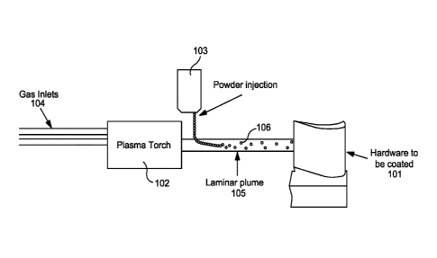
[0012] Figure 1 shows a process schematic in accordance with one
aspect of
the present invention;
[0013] Figure 2 shows a block flow diagram in accordance with one
aspect of
the present invention;
[0014] Figure 3a illustrates a representative heat flux profile of a
turbulent
plasma plume;
[0015] Figure 3b illustrates a heat enthalpy profile as a function of
a radial
location or Figure 3a;
-4-
CA 03144088 2021-12-16
WO 2021/118664
PCT/US2020/050168
[0016] Figure 3c show a cross-sectional view of the energy profile of
the
turbulent plasma plume of Figure 3a;
[0017] Figure 4a illustrates an exemplary heat flux profile of a
laminar
plasma plume in accordance with the principles of the present invention;
[0018] Figure 4b illustrates a heat enthalpy profile as a function of
a radial
location for Figure 4a;
[0019] Figure 4c shows a cross-sectional view of the energy profile of
the
laminar plasma plume of Figure 4a;
[0020] Figure 5a shows x-ray diffraction data of amorphous phases in a
coating prepared by a conventional turbulent plasma plume as shown in Figures
3a,
3b and 3c;
[0021] Figure 5b shows an optical microscopy image at a magnification
of
200X of the coating of Figure 5a;
[0022] Figure 6a shows x-ray diffraction data in a coating prepared by
a
laminar plasma plume as shown in Figures 4a, 4b and 4c; and
[0023] Figure 6b shows an optical microscopy image at a magnification
of
200X of the coating of Figure 6a.
Detailed Description of the Invention
[0024] The objectives and advantages of the invention will be better
understood from the following detailed description of the embodiments thereof
in
connection. The present disclosure relates to novel coating processes for
producing
improved coatings with increased crystallinity and density. The disclosure is
set out
herein in various embodiments and with reference to various aspects and
features of
the invention.
[0025] The relationship and functioning of the various elements of
this
invention are better understood by the following detailed description. The
detailed
description contemplates the features, aspects and embodiments in various
permutations and combinations, as being within the scope of the disclosure.
The
-5-
CA 03144088 2021-12-16
WO 2021/118664
PCT/US2020/050168
disclosure may further be specified as comprising, consisting or consisting
essentially
of, any of such combinations and permutations of these specific features,
aspects, and
embodiments, or a selected one or ones thereof.
[0026] Prior to emergence of the present invention, a major challenge
in the
deposition of coatings by thermal spraying has been to develop a desired
structure of
the thermal spray coating using a process that is intrinsically non-
equilibrium. In the
case of materials systems such as the rare earth disilicate-based ceramics
used for
environmental barrier coatings, the relatively rapid cooling rates can trap
the coating
into undesirable metastable crystal structures including fully or partially
amorphous
coating structures. These resulting so-called "vitreous coatings" are then
undesirably
prone to crystallization to the equilibrium crystal structures upon high
temperature
service and eventually can lead to cracking and failure of the coating.
[0027] To overcome the above-mentioned challenges, the present
invention
offers a solution which is a notable departure from conventional plasma
coating
processes which utilize turbulent plasma plume flow regimes. In particular,
the
inventors have discovered that a laminar plasma plume with specific attributes
as will
be discussed, can be used to preheat the substrate to a sufficient
temperature,
followed by optimal introduction of powder particles into the in-tact laminar
plasma
plume without disruption of the laminar plasma plume. The particles are heated
by
the laminar plasma plume and accelerate towards the surface of the part or
component to be coated. The term "laminar plasma plume" as used herein and
throughout is intended to mean a plasma plume that is substantially
isenthalpic along
the radial axis of the torch, thereby leading to elimination or significant
reduction of a
radial gradient of the plasma parameters when compared to a traditional
turbulent
plasma plume. The thermal and kinetic energy supplied by the laminar plasma
plume
is capable of depositing a significantly dense and crystalline coating for a
given
application.
[0028] During this inventive process, by means of the relatively
higher heat
flux along the axis of the laminar plume in comparison to conventional
processes, the
-6-
coating and substrate are heated in a controlled manner to a temperature at or
above
the glass transformation temperature of the material being deposited. Creating
and
maintaining the glass transformation temperature is particularly important for
the
deposition of high-quality coatings of materials in which crystallization of
the
equilibrium phase has been historically suppressed by rapid cooling as is the
case for
rare earth disilicate and aluminosilicate environmental barrier coatings.
Unlike
conventional processes that utilize a turbulent plasma plume, the application
of
repeated directed heating of the substrate by the laminar plasma plume while
the
coating accumulates therealong ensures that during the deposition of each pass
or
layer of the thermally sprayed coating there exists the required thermal
energy to
cause both nucleation and growth of the crystals of the desired equilibrium
phase,
while limiting or eliminating the formation of amorphous phases in the
coating. The
use of a laminar plasma as specifically created by the present invention to
possess
certain characteristics reduces and/or eliminates the need for subsequent
thermal
processing of parts or components as a result of elimination or reduced
amounts of
amorphous phases or structures in the resultant coating. On the contrary,
coatings
produced by conventional plasma processes are significantly amorphous and
undergo
crystallization which occurs in service in a manner that causes the coating to
damage.
[0029] An exemplary embodiment of the present invention will be
discussed
with respect to Figures 1, 2, 4a and 4b. The present invention utilizes a
laminar
plasma plume regime to create improved coatings having increased crystallinity
and
increased density. Referring to Figure 1, in one embodiment, a coating process
100 is
used to coat a substrate 101, such as a turbine blade. The process 100
includes
providing a plasma torch, preferably a cascade torch 102 as described in
greater detail
in U.S. Patent Nos. 7,750,265; 9,150549; and 9,376,740 ("the Belashchenko
patents"). The cascade torch 102 may include a cathode module having at least
one
cathode, a pilot insert module, an anode module and at least one inter-
electrode insert
module QED to provide arc stability. A forming module may be located
downstream
-7-
Date Recue/Date Received 2023-05-16
CA 03144088 2021-12-16
WO 2021/118664
PCT/US2020/050168
of anode arc root for shaping and/or controlling the velocity profile of a
plasma
stream exiting the region of the anode arc root. For purposes of clarity, the
structural
details of the cascade torch 102 have been omitted in order to better
illustrate the
principles of using a laminar plasma plume to create improved coatings with
higher
crystallinity and density in accordance with the principles of the present
invention.
Gas inlets to the torch provide a combination of plasma process gas and
carrier
gasses.
[0030] A coating process standoff distance is established that is a
minimum of
3 inches or greater. As used herein and throughout, the term "coating process
standoff distance" is the distance measured from the outlet of the cascade
torch 102 to
the substrate 101 (e.g., turbine blade). In this regard, the substrate 101 to
be coated is
located at the approximate termination (i.e., distal end) of the laminar
plasma plume
105 which is three inches or more from the outlet of the plasma torch 102.
[0031] An electrical power supply (not shown) is operably connected to
supply power to the cascade torch 102. A plasma gas 104 is supplied into the
inlet of
cascades torch 102. The plasma gas 104 is ionized within the torch 102 to
produce a
laminar plasma plume 105. The laminar plasma plume 105is substantially
isenthalpic
along the radial axis of the torch 102 (Figures 4a and 4b), thereby leading to
elimination or a significantly smaller radial gradient of the plasma
parameters when
compared to a traditional turbulent plasma plume, which has a enthalpy profile
that
varies significantly with the radial axis of the torch 102 (Figures 3a and
3b). The
laminar plasma plume 105 is created to specifically extends from the outlet of
the
torch 102 and contact the surface of the substrate 101 to be coated, thereby
having a
longitudinal length substantially equal to the coating process standoff
distance. The
process 100 minimizes or eliminates eddies and minimizes atmospheric air
entrainment into the laminar plasma plume 105 in comparison to the process of
Figures 3a and 3b. By minimizing eddies in the laminar plasma plume 105 in
comparison to that of turbulent plume shown in Figures 3a, the enthalpy and
associated heat content of the laminar plasma plume 105 can be more
effectively
-8-
CA 03144088 2021-12-16
WO 2021/118664
PCT/US2020/050168
focused towards the substrate 101, but in a manner that does not impart
excessive
heat onto the substrate 101 such that thermal damage occurs. The thermal
energy
from the laminar plasma plume 105 is transferred in a controlled manner
towards the
substrate 101 in a direction that is substantially parallel to the
longitudinal axis of the
laminar plasma plume 105.
[0032] The laminar plasma plume 105 pre-heats the substrate to a
temperature
that is at or above a glass transition temperature of the resultant coating to
be
deposited. Of particular significance and benefit is the elimination of
auxiliary
heating sources when pre-heating the substrate 101. By keeping the substrate
101
and the coating built-up thereon at or above the glass transition temperature,
conditions favoring crystal formation of the resultant formation are
established.
Specifically, the powder particles 106 upon impinging the substrate 101
undergo a
cooling rate that is suitable to reduce or minimize formation of amorphous
phases in
comparison to a coating produced by a turbulent plasma plume of Figures 3a and
3b.
[0033] With the substrate 101 preheated with laminar plasma plume 105,
and
the laminar plasma plume 105 structurally in-tact with its distal end touching
the
substrate 101, the powder particles can now be introduced. Hopper 103 can
introduce
the powder particles 106 into the laminar plume 105. One example of a
configuration
for introducing the powder is shown in Figure 1. The powder particles 106 are
shown
to be radially injected into the laminar plasmas plume 105 at a position that
is
downstream of the torch 102. Carrier gas is introduced at the gas inlet to the
plasma
torch 102. The introduction of powder particles 106 occurs at carrier gas flow
rates
and at an injection angle that does not disrupt the laminar plasma plume 105.
The
carrier gas entrains the powder particles 106 within the laminar plume 105 as
shown
in Figure 1 and the entrainment is also without disruption of the laminar
plasma
plume 105. Although radial injection is shown, it should be understood that
other
injection configurations are contemplated, including, by way of example an
axial
injection of powder particles 106 with a suitable inert carrier gas.
-9-
CA 03144088 2021-12-16
WO 2021/118664
PCT/US2020/050168
100341 The powder particles 106 are heated within the laminar plasma
plume
105 such that substantially all of the particles 106 become molten. The powder
particles 106 in such molten state are accelerated towards the substrate 101.
The
power particles impinge the substrate 101 and crystallize to form a resultant
coating
with increased crystallinity and density. The integrity of the laminar plasma
plume
105 is maintained during the formation of the coating. Additionally, the
laminar
plasma plume 105 remains in contact with the substrate 101 to ensure that the
coating
accumulating onto the substrate 101 is sufficiently heated and maintained at a
temperature at or above the glass transition temperature of the resultant
coating. The
resultant coating possesses sufficient crystallinity such that no post-heat
treatment or
auxiliary heating is required.
[0035] A high level block flow diagram representative of the key steps
of the
of the present invention in one aspect and as described hereinabove with
respect to
process 100 is shown in Figure 2. Process 100 requires generating a laminar
plasma
plume (step 201); preheating the part/substrate to be coated to a temperature
at or
above the glass transition temperature of the coating material (step 202);
injection of
powder into the laminar plasma plume 105 while maintaining the laminarity of
the
plasma plume 105 (step 203); and coating the part/substrate while maintaining
the
coating temperature at or above the glass transition temperature of the
coating
materials (step 204).
[0036] Various improved coatings with increased crystallinity and
density can
be produced using the techniques of the present invention. For example, in
another
embodiment of the present invention, it has been found that by using a high
enthalpy
plasma torch in a laminar flow regime at relatively long standoff distances in
comparison to conventional turbulent plasma flow processes (Figures 3a and
3b), it is
possible to deposit coatings of rare earth disilicates with significantly high
levels of
high temperature stable crystalline phases present without the use of
auxiliary heating
or post deposition heat treatments. The method for such deposition involves
utilizing
the methodology of the present invention, namely: (i) operating a plasma
cascade
-10-
CA 03144088 2021-12-16
WO 2021/118664
PCT/US2020/050168
torch with a series of inner electrode inserts such that it operates in the
laminar flow
regime within which a laminar plasma plume is created; (ii) preheating the
substrate
using the laminar plasma plume; (iii) entraining the powder feedstock in the
laminar
plasma plume to heat the powder particles above its melting temperature
without
disruption of the laminar plasma plume; (iv) accelerating the powder particles
towards the surface of the substrate; and (v) impinging the particles onto the
surface
of the substrate while the laminar plasma plume remains in contact with the
surface
of the substrate and is concurrently heating the substrate such that the
impacted
molten particles cool at a rate to reduce, eliminate or minimize formation of
amorphous phases relative to conventional processes so that vitrification
(e.g.,
formation of non-crystalline, amorphous materials) is predominantly
suppressed.
[0037] The laminar plasma plume 105 as utilized by the present
invention is
created with specific power and thermal heat transfer characteristics
favorable for
creating the improved coatings, as will now be described with respect to
Figures 4a
and 4b. Figure 4a shows that the laminar plasma plume 105 does not entrap
eddies
which leads to a significantly longer plasma plume 105 with predominately
unidirectional heat flow along the axis of the plasma plume. The plume 105 can
then
be positioned such that the part 101 to be coated is at or near the distal end
of the
laminar plasma plume 105 leading to significant heat transfer to the part 101
during
deposition.
[0038] The laminar plasma plume 105 is defined, at least in part, by a
longitudinal length along a longitudinal axis of the laminar plasma plume 105
that
extends from the outlet of the cascade torch 102 to the substrate 101. The
longitudinal length remains substantially constant during the process 100 and
is
substantially equal to the standoff distance, which is 3 inches at minimum or
greater.
The laminar plasma plume 105 can be further characterized as columnar-like in
structure as can be seen in Figure 4a. The columnar-like structure allows the
enthalpy profile (Figure 4b) and associated heat content (Figure 4a) to remain
constant and distributed uniformly and along the radial direction of the torch
102.
-11-
CA 03144088 2021-12-16
WO 2021/118664
PCT/US2020/050168
The enthalpy and heat content associated with the laminar plasma plume 105 is
not
localized in front of the torch 102. Additionally, a cross-section of the
laminar
plasma plume 105 in Figure 4c indicates that the magnitude of heat losses
radially
outwardly is smaller in comparison to that of the turbulent plasma plume show
in
cross-section in Figure 3c.
[0039] On the contrary, referring to Figures 3a, 3b and 3c, strong
eddies are
shown around and within the turbulent plasma plume, which truncates the plasma
plume and leads to significant shorter observed plumes and dramatically
increased
heat transfer radially out from the axis of the plume. This is show in the
cross-
sectional view of the plasma plume and position verses enthalpy curves, both
of
which show removal of energy and heat from the plasma plume in the radial
direction.
[0040] The characteristics of the laminar plasma plume 105 as created
by the
present invention collectively contribute to form a localized deposition spot
temperature of the heated substrate 101 that is greater than a corresponding
localized
deposition spot temperature created by a conventional plasma turbulent plasma
plume
of Figures 3a and 3b, thereby allowing formation of increased crystalline and
densified coatings. The use of a laminar plasma plume 105 to develop highly
crystalline coatings is based on the ability of the laminar plasma plume 105
to create
a columnated plasma with a predominantly oriented unidirectional heat flux
that
preferentially directs heat flow in a controlled manner from the plasma along
the axis
of the torch. This concentration of thermal energy can then be directed at the
part to
be coated.
[0041] While the preferred embodiments of the process have been set
forth
above, the following examples are intended to provide a basis for comparison
of the
present invention, with other coating processes, but they are not to be
construed as
limiting the invention. X-ray diffraction and optical microscopy images of as-
sprayed coating cross sections deposited by the present invention were
performed and
-12-
CA 03144088 2021-12-16
WO 2021/118664
PCT/US2020/050168
compared to the same for coatings produced by conventional state of the art
technology as described in the Examples below.
COMPARATIVE EXAMPLE 1 (Turbulent Plasma Plume Conventional
Process)
[0042] A conventional turbulent plasma plume as shown in Figures 3a,
3b and
3c was utilized to produce a rare earth di silicate (RE2Si207) coating. A
turbulent
plasma plume was created using a F4 plasma torch (commercially available from
Metco) at typical operating parameters. A coating process standoff distance of
4
inches was created. The torch was used to pre-heat the substrate before the
coating
was applied. The turbulent plasma plume was non-isenthalpic and not stable.
The
plume was relatively short (in comparison to that of Example 1) and
triangularly-
shaped. The turbulent plasma plume did not contact the substrate surface
during the
coating. It was determined that the turbulent plasma plume exhibited turbulent
eddies.
[0043] X-ray diffraction data was obtained on the coating and the
results
reported in Figure 5a. The x-ray diffraction data indicated significant x-ay
band
characteristics indicative of non-crystalline material present in the coating.
The
results indicated unacceptably high levels of amorphous phases that required
subsequent post heat treatment or auxiliary heating.
[0044] The optical microscopy images at a magnification 200X of the
coating
was obtained and is shown at Figure 5b. The optical microscope image exhibited
the
presence of unacceptably high amounts of unmelted particles and porosity, both
of
which are detrimental to the effectiveness of the coating.
EXAMPLE 1 (Laminar Plasma Plume Invention)
[0045] A laminar plasma plume process as shown in Figures 4a, 4b and
4c
was utilized to produce a rare earth disilicate (RE2Si207) coating in the as-
sprayed
condition. A coating process standoff distance of more than 3 inches was
created. A
-13-
CA 03144088 2021-12-16
WO 2021/118664
PCT/US2020/050168
laminar plasma plume was created using a cascade torch. The laminar plasma
plume
had a columnar-like structure as shown in Figure 4a. The plume had a
longitudinal
length longer that of the turbulent plasma plume. The temperature of the
substrate
was pre-heated to a temperature at or above the glass transition temperature
of the
coating. The plume was isenthalpic. The stability of the laminar plasma plume
was
observed to be maintained throughout the coating process. The presence of
eddies
was not detected.
[0046] X-ray diffraction data was obtained on the coating and the
results
reported in Figure 6a. The x-ray diffraction data indicated predominately
distinct and
narrow full width half maximum crystalline peaks that identify the C-type rare
earth
disilicate crystal structure. The x-ray diffraction data in Figure 6a
indicated a
significantly lower magnitude of the amorphous x-ray band within the coating
in
comparison to that produced by the turbulent plasma plume of Comparative
Example
1. This diffraction data was indicative of a notable decrease in the amount of
amorphous phase in the coating. It was therefore concluded that the coating
had
higher crystallinity than that produced in Comparative Example 1. The coating
did
not require subsequent auxiliary heating or a post heat treatment step.
[0047] The optical microscopy images at a magnification of 200X of the
coating was obtained and is shown at Figure 6b. The micrograph of the coating
cross-section indicated a denser coating in comparison to that of Comparative
Example 1. It was visually observed to be free of unmelted particles. Cracking
and
interconnected porosity in the coating were observed to be minimal.
[0048] While it has been shown and described what is considered to be
certain embodiments of the invention, it will, of course, be understood that
various
modifications and changes in form or detail can readily be made without
departing
from the spirit and scope of the invention. It is, therefore, intended that
this invention
is not limited to the exact form and detail herein shown and described, nor to
anything less than the whole of the invention herein disclosed and hereinafter
claimed.
-14-