Note: Descriptions are shown in the official language in which they were submitted.
WO 2021/022088
PCT/US2020/044343
INTRACRANIAL DELIVERY OF MEDICINAL SOLUTION
CROSS-REFERENCE TO RELATED APPLICATIONS
[0001] This application claims priority to, and the
benefit of, U.S. Provisional Patent Application
No. 62/881,875 filed on August 1, 2019 and titled Devices, Systems and Methods
for Intracranial
Delivery of Therapeutic Agents to Treat Brain Tumors, which is incorporated
herein by reference in its
entirety for all purposes.
FIELD OF THE INVENTION
[0002] Embodiments relate to apparatuses, systems and
methods for the treatment of adverse
neurological conditions, such as for treatment of brain tumors or other
cranial growths.
BACKGROUND
[0003] Cancer of the brain and other nervous system
cancers are a leading cause of death for men
and women. For example, glioblastoma multiforme is the most commonly diagnosed
primary brain tumor
in adults, with an incidence of 2-3 cases per 100,000 population per year.
This is a particularly lethal and
fast-acting form of cancer, as the median life expectancy without treatment is
approximately 4.5 months
and the maximum life expectancy without treatment is generally considered to
be 15 months.
[0004] Conventional therapies employed to treat undesired
growths in the brain include surgical
resection, radiotherapy, and chemotherapy. Therapies may be repeated, or two
or more therapies may be
used in combination or sequence. These conventional therapies each suffer well-
known drawbacks and
are often only marginally effective for treating aggressive growths such as
glioblastoma.
[0005] Major drawbacks of surgical resection include
risks generally associated with cranial and
brain surgery, as well as the risks related to growth inaccessibility.
Attempts to remove growths or
portions of growths surrounded or intercalated in healthy brain tissue can
cause injury to the healthy
tissue, thus the physician and subject must choose either possible brain
injury to fully resect the growth,
or designating the growth or portions of the growth as inaccessible for
resection. Inaccessibility is a
particular problem for growths such as glioblastomas that invade many
different areas of healthy tissue
within the brain. Due to inaccessibility or other considerations, surgical
removal of an entirety of a
growth is not always practicable, and any non-removed portions of the growth
can continue to grow.
[0006] With respect to radiotherapy and chemotherapy, a
dosage required to kill growth cells
generally also results in the killing of healthy cells. An additional
complication with chemotherapy is that
the blood-brain barrier often creates impediments to delivery into the brain
by conventional delivery
methods (e.g., intravenous (IV) infusion, subcutaneous injection, or oral
delivery), thus requiring even
higher doses of chemotherapy. Side effects from radiotherapy and chemotherapy
can therefore be
prohibitively severe, such as damage to vital areas of the brain resulting in
a reduction of speech, motor
skills, and cognitive skills. Further, many drugs are unable to cross the
blood brain barrier in any
- 1 -
CA 03144725 2022-1-18
WO 2021/022088
PCT/US2020/044343
meaningfid amount. Additionally, for inoperable glioblastomas (which are
many), the median survival
time using a combination of radiotherapy and chemotherapy treatments is still
only about 15 months.
SUMMARY OF THE INVENTION
100071 In an embodiment, a system for delivery of a
medicinal solution to a tissue site in a brain of a
subject includes a catheter, a cranial buff hole stopple, a connecting member,
an anchoring element, and a
connector tube. The catheter has a proximal end and a distal end, and defines
at least one catheter lumen.
The stopple defines a stopple opening structured for advancement of the
catheter therethrough. The
stopple includes a plug structured to be inserted into a burr hole in a
cranium of the subject, the plug
including at least one seal positioned on a wall of the stopple opening to
form a fluidic seal with an
exterior of the catheter. The stopple further includes a flange structured to
engage an outer surface of a
skull of the subject when the plug is inserted into the buff hole, the flange
defining a flange opening on a
side portion of the flange and defining at least one groove on a top portion
of the flange, the at least one
groove structured to engage and retain the catheter. The connecting member has
a proximal end and a
distal end, the distal end structured to be coupled to the proximal end of the
catheter, the connecting
member defining at least one connecting member lumen. The anchoring element
engages the flange
opening and is structured to secure the connecting member to the flange. The
connector tube has a
proximal end and a distal end, the distal end structured to be coupled to the
connecting member proximal
end, the connector tube defining at least one connector tube lumen. The at
least one catheter lumen, the at
least one connecting member lumen, and the at least one connector tube lumen
are structured to provide
at least one flow path, when assembled together, for delivery of the medicinal
solution to the tissue site in
the brain.
100081 In an embodiment, a method for the intracranial
delivery of an active agent to a brain to
focally treat a growth in a cranium of a subject includes: positioning a burr
hole stopple in a burr hole in
the cranium, the burr hole stopple defining a sealable opening; advancing a
catheter through the burr hole
stopple opening such that a tip of the catheter is positioned at a tissue site
in the brain within or in
proximity to the growth, the catheter defining a fluidic lumen having at least
one aperture at a distal
portion of the catheter; affixing a proximal portion of the catheter to a
fixation feature in the burr hole
stopple; creating a flow path between the tissue site and a pump operatively
coupled to a reservoir
containing a medicinal solution comprising the active agent; and pumping the
medicinal solution from the
reservoir to the tissue site via the flow path; wherein a flow rate and a
duration of delivery are selected
based on an established model so as to achieve a selected steady state
diffusion volume of medicinal
solution in the brain tissue.
POW] In an embodiment, a method for focally treating a
brain growth includes: intracranially
delivering to a tissue site in the brain, within or in proximity to the
growth, a medicinal solution
comprising an active agent which is degraded at a pH at or above that found in
healthy brain tissue,
wherein the solution comprises substantially no buffering agent; and wherein
the active agent has a
- 2 -
CA 03144725 2022-1-18
WO 2021/022088
PCT/US2020/044343
cytotoxic effect on cancerous tissue in the growth and is deactivated upon
contact with or after entering
into healthy brain tissue surrounding the growth.
[0010] Further details of these and other embodiments and
aspects of the invention are described
more fully below, with reference to the attached drawing figures.
BRIEF DESCRIPTION OF THE DRAWINGS
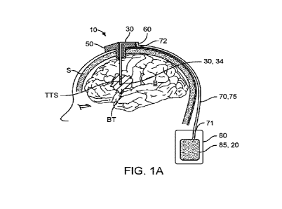
[0011] Fig. 1A illustrates an embodiment of an
intracranial drug delivery system.
[0012] Fig. 1B illustrates a diffusion volume of an
active agent created by delivery of a medicinal
solution to a delivery site in the brain using the embodiment of the system of
Fig. 1A.
[0013] Fig. 1C is an enlarged view of Fig. 1A.
[0014] Fig. 1D is an enlarged view of Fig. 1B.
[0015] Fig. 2A illustrates an embodiment of a burr hole
stopple.
[0016] Fig. 2B illustrates an embodiment of a burr hole
stopple.
[0017] Fig. 3A, Fig. 3B, Fig. 3C, and Fig. 3D illustrate
an embodiment of placement of a catheter
using a stylette at a tissue site in the brain. Fig. 3A shows advancement of
the stylette; Fig. 3B shows
advancement of the catheter over the stylette; Fig_ 3C shows placement of the
catheter tip in the brain
growth; and Fig. 3D shows the positioned catheter connected to the
intracranial drug delivery system.
[0018] Fig. 4A illustrates an embodiment of an
intracranial drug delivery system.
[0019] Fig. 48 illustrates an embodiment of an
intracranial drug delivery system.
[0020] Fig. 5A illustrates an embodiment of a burr hole
stopple including an inductive coil and
associated circuitry operatively coupled to the coil.
[0021] Fig. 5B illustrates an embodiment of a burr hole
stopple including an inductive coil and
associated circuitry operatively coupled to the coil.
[0022] Fig. 5C illustrates an embodiment of communication
between a burr hole stopple and an
external communication device.
[0023] Fig. 6A illustrates an embodiment of communication
between a burr hole stopple and a head
covering.
[0024] Fig. 68 is a view illustrating an embodiment of
the head covering of Fig. 6A,
[0025] Fig. 7 is a graph of medicinal solution flow rate
versus time illustrating embodiments of
different delivery regimens.
[0026] Fig. 8 is a graph illustrating the generation of
different steady state diffusion volumes of an
active agent for varying flow rates of medicinal solution infused into a
tissue site in the brain.
[0027] Fig. 9 is a flow chart of an algorithm for focally
treating a brain growth in a subject using
modelled correlations of steady state diffiision volumes of an active agent
versus flow rate of a medicinal
solution.
- 3 -
CA 03144725 2022-1-18
WO 2021/022088 PCT/US2020/044343
DETAILED DESCRIPTION
[0028] Described herein are techniques and devices used
for intercranial drug delivery to treat brain
growths and other neurological conditions. The intracranial drug delivery may
be into brain tissue or into
cerebrospinal fluid (CSF) in the cranium such as in ventricles of the brain.
[0029] Before discussing details of the techniques and
devices for intercranial drug delivery, a few
conventions are provided for convenience of the reader.
[0030] Various abbreviations are used herein for standard
units, such as deciliter (dl), milliliter (ml),
microliter (pl), international unit (IU), centimeter (cm), millimeter (mm),
kilogram (kg), gram (gm),
milligram (mg), microgram (jig), millimole (mM), degrees Celsius ( C), degrees
Fahrenheit ( F), millitorr
(mTorr), hour (hr), or minute (min).
[0031] When used in the present disclosure, the terms
"e.g.," "such as", "for example", "for an
example", "for another example", "examples of", "by way of example", and
"etc." indicate that a list of
one or more non-limiting example(s) precedes or follows; it is to be
understood that other examples not
listed are also within the scope of the present disclosure.
[0032] As used herein, the singular terms "a," "an," and
"the" may include plural referents unless the
context clearly dictates otherwise_ Reference to an object in the singular is
not intended to mean "one and
only one" unless explicitly so stated, but rather "one or more."
[0033] The term "in an embodiment" or a variation thereof
(e.g., "in another embodiment" or "in one
embodiment") refers herein to use in one or more embodiments, and in no case
limits the scope of the
present disclosure to only the embodiment as illustrated andVor described.
Accordingly, a component
illustrated and/or described herein with respect to an embodiment can be used
in another embodiment
(e.g., in another embodiment illustrated and described herein, or in another
embodiment within the scope
of the present disclosure and not illustrated and/or not described herein).
[0034] The term "component" refers herein to one item of
a set of one or more items that together
make up a device, formulation or system under discussion. A component may be
in a solid, powder, gel,
plasma, fluid, gas, or other form_ For example, a device may include multiple
solid components which are
assembled together to structure the device and may further include a liquid
component that is disposed in
the device. For another example, a formulation may include two or more
powdered and/or fluid
components which are mixed together to make the formulation.
[0035] The term "design" or a grammatical variation
thereof (e.g., "designing" or "designed") refers
herein to characteristics intentionally incorporated into a design based on,
for example, estimates of
tolerances related to the design (e.g., component tolerances and/or
manufacturing tolerances) and
estimates of environmental conditions expected to be encountered by the design
(e.g., temperature,
humidity, external or internal ambient pressure, external or internal
mechanical pressure, external or
internal mechanical pressure stress, age of product, physiology, body
chemistry, biological composition
of fluids or tissue, chemical composition of fluids or tissue, pi-1, species,
diet, health, gender, age,
ancestry, disease, tissue damage, shelf life, or the combination of such); it
is to be understood that actual
tolerances and environmental conditions before and/or after delivery can
affect such designed
- 4 -
CA 03144725 2022-1-18
WO 2021/022088
PCT/US2020/044343
characteristics so that different components, devices, formulations, or
systems with a same design can
have different actual values with respect to those designed characteristics.
Design encompasses also
variations or modifications to the design, and design modifications
implemented after manufacture.
[0036] The term "manufacture" or a grammatical variation
thereof (e.g., "manufacturing" or
"manufactured") as related to a component, device, formulation, or system
refers herein to making or
assembling the component, device, formulation, or system. Manufacture may be
wholly or in part by hand
and/or wholly or in part in an automated fashion.
[0037] The term "structured" or a grammatical variation
thereof (e.g., "structure" or "structuring")
refers herein to a component, device, formulation, or system that is
manufactured according to a concept
or design or variations thereof or modifications thereto (whether such
variations or modifications occur
before, during, or after manufacture) whether or not such concept or design is
captured in a writing.
[0038] The term "body" refers herein to an animalia body
having a GI tract.
[0039] The term "subject" refers herein to a body into
which an embodiment of the present
disclosure is, or is intended to be, delivered. For example, with respect to
humans, a subject may be a
patient under treatment of a health care professional.
[0040] The term "fluid" refers herein to a liquid or gas,
and encompasses moisture and humidity.
The term "fluidic environment" refers herein to an environment in which one or
more fluids are present.
[0041] The term "biological matter" refers herein to
blood, tissue, fluid, enzymes, interstitial fluid,
and other secretions of a body.
[0042] The term "medicinal solution" refers herein to a
preparation intended for a therapeutic,
diagnostic, or other biological purpose in any form. Each medicinal solution
can include one or more
components, and a device or system can include one or more medicinal
solutions. A component of a
medicinal solution can be, for example, a pharmacological agent, a DNA or
SiRNA transcript, a cell, a
cytotoxic agent, a vaccine or other prophylactic agent, a nutraceutical agent,
a vasodilator, a
vasoconstrictor, a delivery enhancer, a delay component, an excipient, or a
diagnostic agent. A
component of a medicinal solution that is included in the medicinal solution
for the purpose of invoking a
biological effect in tissue of a body, such as any of the foregoing or other
component, is referred to herein
for convenience as an "active agent".
[0043] A pharmacological agent can be, for example, an
antibiotic, a nonsteroidal anti-inflammatory
drug (NSAID), an angiogenesis inhibitor, a neuroprotective agent, a
chemotherapeutic agent, an antibody,
a nanobody, a hormone, or a biologically active variant or derivative of any
of the foregoing.
[0044] A cell can be, for example, a stem cell, a red
blood cell, a white blood cell, a neuron, or other
viable cell. Cells can be produced by or from living organisms or contain
components of living
organisms. A cell can be allogeneic or autologous.
[0045] A vasodilator can be, for example, l-arginine,
sildenafil, a nitrate (e.g., nitroglycerin), or
epinephrine.
[0046] A vasoconstrictor can be, for example, a
stimulant, an amphetamine, an antihistamine,
epinephrine, or cocaine.
- 5 -
CA 03144725 2022-1-18
WO 2021/022088
PCT/U52020/044343
[0047] A delivery enhancer can be, for example, a
permeation enhancer, an enzyme blocker, an
antiviral drug such as a protease inhibitor, a pH modifier, a surfactant, a
fatty acid, a chelating agent, or a
chitosan. A delivery enhancer can, for example, serve as a delivery medium for
delivery of a component
of a medicinal solution, or serve to improve absorption of a component of a
medicinal solution into the
body.
[0048] An excipient can be, for example, a binder, a
disintegrant, a superdisintegrant, a buffering
agent, an anti-oxidant, or a preservative. Excipients can provide a medium for
a component of a medicinal
solution (e.g., for assisting in manufacture), or to preserve integrity of a
component of a medicinal
solution (e.g., during manufacture, or during storage).
[0049] A diagnostic agent can be, for example, a sensing
agent, a contrast agent, a radionuclide, a
fluorescent substance, a luminescent substance, a radiopaque substance, or a
magnetic substance.
[0050] The term "degrade" or a grammatical variation
thereof (e.g., "degrading", "degraded",
"degradable", and "degradation") refers herein to weakening, partially
degrading, or fully degrading, such
as by dissolution, chemical degradation (including biodegradation),
decomposition, chemical
modification, mechanical degradation, or disintegration, which encompasses
also, without limitation,
dissolving, crumbling, deforming, shriveling, or shrinking. The term "non-
degradable" refers to an
expectation that degradation will be minimal, or within a certain acceptable
design percentage, for at least
an expected duration in an expected environment.
[0051] The term "degradation rate" or a grammatical
variation thereof (e.g., "rate of degradation")
refers herein to a rate at which a material degrades. A designed degradation
rate of a material in a
particular implementation can be defined by a rate at which the material is
expected to degrade under
expected conditions (e.g., in physiological conditions) at a target delivery
site. A designed degradation
time for a particular implementation can refer to a designed time to complete
degradation or a designed
time to a partial degradation sufficient to accomplish a design purpose (e.g.,
breach). Accordingly, for
example, a designed degradation time can be specific to a component and/or
specific to expected
conditions at a target delivery site.
[0052] The terms "substantially" and "about" are used
herein to describe and account for small
variations. For example, when used in conjunction with a numerical value, the
terms can refer to a
variation in the value of less than or equal to 10%, such as less than or
equal to 5%, less than or equal
to 4%, less than or equal to 3%, less than or equal to 2%, less than or
equal to 1%, less than or equal
to +0.5%, less than or equal to 10.1%, or less than or equal to 0.05%.
[0053] As used herein, a range of numbers includes any
number within the range, or any sub-range if
the minimum and maximum numbers in the sub-range fall within the range. Thus,
for example, "< 9" can
refer to any number less than nine, or any sub-range of numbers where the
minimum of the sub-range is
greater than or equal to zero and the maximum of the sub-range is less than
nine. Ratios may also be
presented herein in a range format. For example, a ratio in the range of about
1 to about 200 should be
understood to include the explicitly recited limits of about 1 and about 200,
and also to include individual
- 6 -
CA 03144725 2022-1-18
WO 2021/022088
PCT/US2020/044343
ratios such as about 2, about 35, and about 74, and sub-ranges such as about
10 to about 50, about 20 to
about 100, and so forth.
[0054] The discussion now continues with respect to
delivery of a medicinal solution.
[0055] There is a need for improved techniques for
delivery of a medicinal solution for the treatment
of brain growths and other neurological conditions. For convenience, the term
"growth" as used herein
encompasses tumors, cancers, and other growths to be treated (whether or not
tumorous and/or
cancerous). One approach is to use intracranial delivery into brain tissue or
into CSF in the brain.
Intracranial delivery has an advantage of delivery of an active agent directly
to, or into, a growth or other
targeted area, which can minimize side effects associated with other
treatments (e.g., IV chemotherapy)
because the intracranially delivered dose can be much lower and delivery is
largely confined to the cranial
cavity. Intracranial delivery poses a number of challenges, which are
addressed herein. For example, one
challenge is to fixate a catheter to maintain a placement of the catheter in
the cranium and to minimize
movement of the catheter within the cranium to prevent adverse effects on
healthy brain tissue. Other
challenges include preventing backflow of medicinal solution or CSF from the
brain, avoiding cerebral
edema from over-delivery of medicinal solution into the brain, and avoiding
under-delivery of an active
agent due to hindered flow of medicinal solution through the catheter.
[0056] Various embodiments provide techniques and devices
for delivering a medicinal solution
intracranially. Such medicinal solutions can include one or more active agents
to provide targeted focal
treatment of brain growths.
[0057] Fig. 1A ¨ Fig. 6B illustrate embodiments of an
intracranial drug delivery system 10 for
intracranial delivery of a medicinal solution 20 to a target tissue site
(TI'S) in a brain 'B' of a subject.
System 10 includes a catheter 30, a stylette 40 (an introducer member for
introducing catheter 30 into the
TTS), a cranial burr hole stopple 50 inserted into a burr hole 'RFT in a skull
'S', a connecting member 60,
a connector tube 70 (a flexible tubular member), and a fluid delivery system
such as a pump 80.
[0058] Pump 80 is coupled to a proximal end 71 of
connector tube 70, a distal end 72 of connector
tube 70 is coupled to a proximal end 61 of connecting member 60, and a distal
end 62 of connecting
member 60 is coupled to a proximal end 31 of catheter 30. Thus, a flow path 75
is defined from pump 80
to and through catheter 30.
[0059] Flow path 75 may include one or more lumens. Flow
path 75 includes at least one fluidic
lumen fluidically coupled between pump 80 and distal end 32 of catheter 30 for
liquid flow (e.g., for
providing medicinal solution 20) through flow path 75 to the TTS. In an
embodiment, flow path 75
includes two or more fluidic lumens, each fluidically coupled between pump 80
and distal end 32 of
catheter 30, where two or more of the fluidic lumens are not fluidically
coupled together, such that at least
two different fluids (e.g., including medicinal solution 20) can be provided
intracranially (e.g.,
substantially concurrently, sequentially, or in an overlapping regimen).
100601 In an embodiment, flow path 75 further includes at
least one lumen for distributing one or
more electrical conductors (each such lumen referred to herein as a conductor
lumen), to establish
electrical coupling between two or more components of system 10. For example,
electrical conductors
- 7 -
CA 03144725 2022-1-18
WO 2021/022088
PCT/US2020/044343
may be distributed between pump 80 and distal end 32 of catheter 30, between
pump 80 and stopple 50,
between pump 80 and a sensor positioned to detect a condition in or on
connecting member 60 or
connector tube 70, between catheter 30 and stopple 50, between stopple 50 and
a sensor positioned to
detect a condition in or on connecting member 60 or connector tube 70, or
other electrical coupling
between components. In an embodiment, flow path 75 includes at least one
conductor lumen that does not
extend an entirety of the length of flow path 75. For example, flow path 75
may include a first conductor
lumen extending between pump 80 and stopple 50 and a second conductor lumen
extending between
stopple 50 and distal end 32 of catheter 30, where the first conductor lumen
and the second conductor
lumen do not meet.
100611 An electrical conductor may be, for example: a
wire; twisted or braided wire filaments
forming a multifilament wire; a trace; or a printed conductive ink. An
electrical conductor allows for
energy propagation, such as in the form of delivered power or in the form of
one or more signals. A signal
may be transmitted on a single electrical conductor, or on multiple electrical
conductors (e.g., two wires
for higher current capability, two wires for signal and return, three wires
for signal, return, and offset, or
three wires for positive, negative, and ground). Multiple electrical
conductors together may additionally
or alternatively be used implement a bus, such as is used for serial or
parallel communication protocols.
[0062] Where the various components defining flow path 75
are connected, various connection
techniques may be incorporated, and different connection techniques may be
implemented for different
interfaces along flow path 75. For example, a distal end of one component may
be sized to be inserted
into a proximal end of another component, or a proximal end of one component
may be sized to be
inserted into a distal end of another component. In specific examples, a
portion of catheter 30 at proximal
end 31 can be sized to be inserted into connecting member 60 at distal end 62,
or a portion of connecting
member 60 at distal end 62 can be sized to be inserted into catheter 30 at
proximal end 31. In an
embodiment, one or more components defining flow path 75 include threading,
ridging, flanging, or other
raised sealing feature (any of which is referred to herein as a feature 38 for
convenience) that is structured
to engage and form a fluidic seal between the connected components. Features
38 may additionally be
structured to facilitate fixation of catheter 30 to connecting member 60 to
prevent an accidental
dislodgement of catheter 30 from connecting member 60, such as might occur
from head movement or
from impact to an area of the skull 'S' containing stopple 50. In an
embodiment, a luer-lock or other
adaptor or connector is used at an interface between components.
[0063] In an embodiment, one or more one-way valves 39
are disposed in flow path 75 to prevent
backflow of medicinal solution 20 or CSF. For example, Fig. 1C illustrates
valve 39 near distal end 62 of
connecting member 60, and Fig. 2A illustrates valve 39 near proximal end 31 of
catheter 30. Other
positions for valve 39 are also contemplated, including but not limited to
near distal end 32 of catheter 30.
[0064] One or more sensors may be positioned at one or
multiple locations in flow path 75 to detect
backflow, turbulence, or reduced flow (e.g., due to a blockage). Fig. 4A
illustrates an embodiment in
which a sensor 67 is positioned near distal end 62 of connecting member 60.
Other positions are also
contemplated along flow path 75. Examples of sensors include a pressure sensor
or a strain gauge.
- 8 -
CA 03144725 2022-1-18
WO 2021/022088
PCT/U52020/044343
[0065] Other sensors (such as pH or oxygen sensors) may
be positioned at distal end 32 of catheter
30 to ascertain properties of tissue at or in the ITS, such as pH or level of
tissue oxygenation which are
indicative of cancerous tissue. Distally placed sensors within catheter 30
may, for example, measure a
concentration of an active agent in tissue at the ITS to allow a medical
professional or system 10 to titrate
or adjust the delivery of medicinal solution 20 to the ITS.
[0066] Catheter 30 defines one or more lumens 33,
including at least on fluidic lumen 33. hi an
embodiment, catheter 30 defines two or more fluidic lumens 33 for delivering
fluid (e.g., medicinal
solution 20). In an embodiment, flow path 75 includes a single lumen for
delivering fluid between pump
80 and the proximal end 31 of catheter 30, and catheter 30 defines two fluidic
lumens 33 to split flow path
75 into two sub-paths within catheter 30. In an embodiment, catheter 30
defines two or more lumens 33,
including at least one fluidic lumen 33 and at least one conductor lumen 33,
and one or more electrical
conductors are disposed in one of the conductor lumens 33, such as to connect
electronics at distal end 32
of catheter 30 to electronics elsewhere in system 10 (e.g., electronics of
stopple 50, electronics of pump
80, or electronics external to system 10).
[0067] Medicinal solution 20 exits catheter 30 from one
or more aperture(s) 34 at or near distal end
32 of catheter 30. Distal end 32 is structured to be positioned at the ITS in
or near a cranial growth
indicated for convenience as a brain tumor `13T'. Distal end 32 can include
one or more features described
herein such as various sensors or atraumatic structures.
[0068] In an embodiment, aperture 34 of catheter 30
corresponds to a single opening at or near distal
end 32 of catheter 30. In an embodiment, aperture 34 is one of multiple
apertures arranged in a pattern
34-p. Pattern 34p may be, for example, a radially distributed pattern for
delivery of medicinal solution 20
to a volume of brain tissue at the ITS, such as apertures 34 radially
distributed at 30, 45, or 60 degree
offsets to one another. In an embodiment, one or more apertures 34 in the
pattern 34-p can be selectively
opened or closed before or after positioning in the brain to produce a
selectable infusion zone at or within
the TI'S. Selective opening and closing can be implemented by means of a
movable shutter (not shown)
positioned in or on catheter 30.
[0069] Catheter 30 may include various features and
components to improve ease of use,
performance, reliability, and/or safety of catheter 30 and/or intracranial
drug delivery system 10. For
example, catheter 30 may include one or more radiopaque or other imaging
markers 36 positioned at a tip
portion of catheter 30 and/or at various intervals along its length to allow
depth of catheter penetration in
the brain to be observed using fluoroscopy or other imaging modality and thus
facilitate advancement of
catheter 30. Markers 36 can be positioned along catheter 30 in consistent or
non-consistent intervals to
allow the physician (or a robot) to assess what length of catheter has been
inserted into the cranium. For
example, markers 36 can be positioned at 1 cm, 2.5 cm, or 5 cm consistent
intervals. For another
example, a first marker 36 and a second marker 36 can be positioned a first
distance from each other, a
third marker 36 can be positioned a second distance from the second marker 36,
a fourth marker 36 can
be positioned a third distance from the third marker 36, and so forth.
- 9 -
CA 03144725 2022-1-18
WO 2021/022088
PCT/US2020/044343
[0070] Markers 36 may include radiopaque, machine
visible, or otherwise detectable indicia. In an
embodiment, catheter 30 is structured to be engaged by effectors of a surgical
robot and can include
adaptors (e.g., a proximal adaptor not shown) or other feature or element
allowing for this capability.
[0071] An outer diameter 300D of catheter 30 is sized to
fit through an opening 51 defined by
stopple 50 while forming a fluidic seal with seals 53 in opening 51. In an
embodiment, outer diameter
300D can be in a range of about 1 mm to about 5 mm, more preferably in an
about 1 mm to about 2 mm
range. In an embodiment, an inner diameter 30ID of lumen 33 of catheter 30 can
be in a range of about
0.1 mm to about 1 mm. A length of catheter 30 can vary depending on depth and
location of the growth to
be treated and size of the subject's head. Examples include catheter lengths
in a range of about 5 cm to
about 30 cm, with specific embodiments of about 10 cm, about 15 cm, about 20
cm, and about 25 cm.
100721 In an embodiment, catheter 30 is structured to be
cuttable for customizable length. For
example, markers 36 may be used to allow medical personnel to cut an exposed
portion of catheter 30 to a
selectable length for those embodiments of catheter 30 which are cuttable. In
specific embodiments, the
properties, materials and structure of catheter 30 are selected to allow a
physician to readily cut catheter
30 to a specific length (before or after insertion into subject brain), while
leaving a clean smooth proximal
end that can still form a good connection with connecting member 60, and while
retaining or regaining
lumen 33 of catheter 30 in an open configuration. These results can be
achieved using flexible and
resilient polymers such as various elastomers including silicones and
polyurethanes as well as various
polyethylenes (e.g., LLDPE or HDPE); the material or materials used may be
cross linked (e.g., by
irradiation) to increase resilience and/or strength, such as hoop resilience
and/or strength, to assure that
lumen 33 retains or regains an open configuration after cutting catheter 30.
[0073] In an embodiment, catheter 30 will be introduced
into opening 51 of stopple 50 and advanced
to the TTS by being advanced over an introducer (e.g., over a stylette 40). As
such, catheter 30 is
structured to have mechanical properties (e.g., pushability or flexibility) so
as to be able to easily track
over the introducer. In an alternative embodiment, catheter 30 is structured
to be introduced and advanced
to the TTS without the need for an introducer. Desirably, the structure,
materials, and dimensions of
catheter 30 are selected to allow it to both track over the introducer while
being advanced into brain
tissue, as well as bend once so positioned to minimize force imparted to
surrounding brain tissue.
[0074] In an embodiment, catheter 30 is formed of a
flexible material. Catheter 30 may include any
number of biocompatible polymers, such as various elastomers (e.g., silicone,
polyurethane, a co-polymer
of silicone or polyurethane, a co-polymer of silicone and polyurethane, or
PEBAX). Various super-elastic
metals may be used, such as NITINOL.
[0075] Desirably, mechanical properties of catheter 30,
including stiffness, are structured such that
catheter 30 including its distal end 32 does not cause injury to brain tissue
during advancement of catheter
30 to the TTS or afterwards. Further, desirably, catheter 30 is structured
such that its advancement into
the brain does not cause adverse physiological or neurologic effects such as
trauma, bleeding, cerebral
edema or motor or cognitive loss. This can be achieved at least in part by
fabricating catheter 30 from low
durometer materials (e.g., silicone or other elastomer). In an embodiment, a
durometer of catheter 30 can
- 10 -
CA 03144725 2022-1-18
WO 2021/022088
PCT/US2020/044343
be in a range of about 20 to about 40. In an embodiment, distal end 32 of
catheter 30, or a tip portion
thereof (e.g., the distal 2 cm to 3 cm of catheter 30), can be made atraumatic
by being made more flexible
than a remaining distal (and/or proximal) portion. For example, such tip
portion of catheter 30 can have a
durometer in a range of about 10 to about 20, while the remaining distal
(and/or proximal) portion can
have a durometer of about 20 to about 40. In an embodiment, a tip portion of
catheter 30 can have an
atraumatic shape, such as rounded edges or a rounded dome.
[0076] In an embodiment, lumen 33 of catheter 30 includes
an inner lining of coiled wire (not
shown) to maintain a patency of lumen 33 if the catheter is put into a bent or
deformed position.
[0077] In an embodiment, catheter 30 is structured to be
steerable, such as through use of materials
which transition from a higher stiffness (less flexible) to a lower stiffness
(more flexible) and back. For
example, shape memory materials (e.g., NITINOL) can change shape and stiffness
in response to changes
in temperature. Use of such stiffness transition materials can also be
employed to transition catheter 30
from a less flexible structure during placement into a more flexible structure
once positioned at the ITS.
In this way, catheter 30 is made more atraumatic after positioning at the TI'S
to reduce risk of trauma or
injury to the brain tissue after placement of catheter 30.
100781 Stylette 40 is elongated, and can have a tissue
penetrating distal tip 41. Desirably, stylette 40
has sufficient stiffness to allow it to be advanced into brain tissue by
manual manipulation. In an
embodiment, stylette 40 includes a proximal adapter 42 to facilitate
advancement by a physician or
advancement by a surgical robot. Stylette 40 will generally include a
resilient biocompatible metal (e.g.,
304V stainless steel) or resilient polymer. Stylette 40 may include a
lubricous coating 43 such as
polytetrafluoroethylene (PTFE) to reduce friction with tissue as well as
reducing friction with catheter 30.
A length of stylette 40 can vary from about 10 cm to about 30 cm, with other
lengths also considered.
Stylette 40 can include one or more visual and/or radiopaque or other markings
45 for medical imaging,
such as at a distal tip 41 of stylette 40 and/or at a position away from
distal tip 41, and/or at other
positions along stylette 40. In an embodiment, multiple markings 45 are used,
and include two or more
markings 45 positioned at intervals (e.g., at 1 cm, 2 cm, 2.5 cm, 5 cm, or 10
cm intervals) to allow the
physician to assess how deep stylette 40 has been inserted into brain tissue
as well as to do so using a
medical imaging modality such as fluoroscopy. Markings 45 may also include
machine visible/detectable
indicia allowing for control of the advancement of stylette 40 by a surgical
robot or other device. In an
embodiment, stylette 40 can be structured to be engaged by effectors of a
surgical robot and can include
one or more adaptors (e.g., corresponding to proximal adaptor 42 or other
adaptor(s)) or other feature or
component allowing for this capability.
100791 In an embodiment, stylette 40 is omitted as a
component of system 10 when system 10 is
commercialized as a kit because stylette 40 is separately commercially
available, or omits stylette 40
because catheter 30 can be structured to be introduced and advanced to the TTS
without the use of a
stylette or other introducing member.
100801 Stopple 50 can be fabricated from a rigid
biocompatible material, such as a rigid polymer
(e.g., high density polyethylene (HDPE), or polyetheretherketone (PEEK)), a
metal (e.g., titanium), or a
-11 -
CA 03144725 2022-1-18
WO 2021/022088
PCT/US2020/044343
combination of materials. Stopple 50 includes opening 51 sized and structured
for advancement of stylette
40 and catheter 30 therethrough and into the brain. Opening 51 can be
centrally positioned with respect to
a lengthwise axis of stopple 50, though in an embodiment, opening 51 can be
positioned off-center, such
as to accommodate other components positioned on or in stopple 50 (e.g.,
electronics or antennas). A
diameter of opening 51 depends in part upon an outer diameter of catheter 30.
In an embodiment, the
diameter of opening 51 can be in a range of about 2 mm to about 20 mm.
[0081] In an embodiment, stopple 50 includes two
portions, a plug 52 and a flange 55. Plug 52 and
flange 55 may be integrally formed, or may be separate components coupled
together. Flange 55 and plug
52 together define opening 51 for passa = e of catheter 30. Plug 52 is sized
and structured to be inserted
into the buff hole `13H' in the skull CS'. Seal 53 is positioned on a wall 54
of opening 51 to form a fluidic
seal with an exterior surface 30s of catheter 30. An outer diameter of plug 52
can be customized for the
buff hole '13H' but will generally be in a range from about 5 mm to about 20
mm, with specific
embodiments of about 10 mm, about 14 mm and about 16 mm. The length of plug 52
can be in a range
from about 2 mm to about 15 mm, with longer and shorter lengths contemplated.
[0082] In an embodiment, flange 55 is structured to
engage and extend over an outer surface of skin
over the skull `S' when plug 52 is inserted into the burr hole 13F1'._ In an
embodiment, flange 55 is
structured to extend over the skull `S' and under the skin, such that flange
55 is engaged with the skull CS'
while a skin flap is peeled back, and the skin flap is then positioned over
flange 55.
[0083] Flange 55 defines an opening 56 on a side portion
of flange 55 for insertion of an anchor 64
affixed to or incorporated with connecting member 60, and defines a groove 57
on a top portion 55t of
flange 55 that is structured to engage and retain catheter 30 such that
movement of catheter 30 is
minimized, particularly that resulting from movement of the subject's head. In
an embodiment, top
portion 55t of flange 55 can include two grooves 57 so as to retain catheter
30 in at least two locations
and/or at least axis and thus further reduce movement of the catheter during
movement of the subject's
head. Groove 57 may also be structured (e.g., through a smaller opening on the
top of groove 57 relative
to a diameter of catheter 30) to allow for catheter 30 to be snapped into
place and held in groove 57.
Further, once so positioned in groove 57, the smaller opening on top of groove
57 may also serve to
protect catheter 30 from forces tending to cause compression of catheter 30
(e.g., if the head is pressed
against a surface or object) including those forces which would cause
compression of lumen 33 of
catheter 30.
[0084] In an embodiment, flange 55 includes electronics,
shown by way of example as circuitry 58,
including components for powering, communicating with, and/or analyzing
signals from sensors (e.g.,
sensor 67) associated with components of system 10. For example, circuitry 58
may correspond to one or
more of a processor or other controller 58c, an RF or other transmitter 581,
or a battery or other power
storage device 58p. Components of circuitry 58 may be disposed on a circuit
board 58b which may be or
may include a flexible circuit.
[0085] In an embodiment, circuitry 58 may be coupled to
an inductive coil 59 embedded or
otherwise disposed in or on top portion 55t of flange 55. Coil 59 may include
various conductive metals
- 12 -
CA 03144725 2022-1-18
WO 2021/022088
PCT/US2020/044343
and/or polymers. Coil 59 may be structured to be used to inductively transfer
power from an inductive
coil of an external device 100 for powering one or more of the electrical
components associated with
system 10, including sensors and/or circuitry 58. Coil 59 may also be
structured as an antenna 59A for
transmitting and receiving signals 110s to an external communication device
110 such as a cellular or
other mobile phone using BLUETOOTH or other standard communication protocol or
a proprietary
protocol. In an embodiment, coil 59 may correspond to a first coil 59' for
inductive power coupling and a
second coil 59" for signal transmission (e.g., RF transmission). Signals 110s
transmitted to external
communication device 110 may include information from one or more sensors 67
disposed on or
associated with catheter 30, connecting member 60 or other component of system
10. Such signals 110s
may also include information from circuitry 58 such as a state of circuitry 58
including power levels,
diagnostic checks and error conditions. Sensor 67 can also send signals 67s to
circuitry 58 for receiving
and processing those signals.
[0086] In an embodiment, external device 100 and/or
external communication device 110 may
correspond to or be incorporated into a head covering 130 (e.g., a skull cap
or hat) worn over stopple 50
as illustrated in Figs. 6A and 6B. Head covering 130 may include its own
conductive coil(s) 139 and
associated circuitry 138 for conductive power coupling and/or transmission of
signals to corresponding
coils in stopple 50. In an embodiment, head covering 130 includes an
attachment means 131 (e.g.,
magnets, or hook-and-loop attaclunent (e.g., VELCRO)) for fixing the head
covering over the area of the
skull '5' containing stopple 50. For magnetic attachment embodiments, portions
of stopple 50, in
particular, flange 55, may include ferrous materials. For hook-and-loop
attachment embodiments, a flap
of biomaterial (not shown) can be sutured over stopple 50, where the
biomaterial includes a portion of
hook-and-loop material structured to engage a portion of hook-and-loop
material disposed on an inside
surface of head covering 130.
[0087] Connecting member 60 defines at least one lumen
63. In an embodiment, connecting member
60 includes one or more pressure or flow sensors 67 positioned within lumen 63
(e.g., on or under a
surface of lumen 63) for sensing pressure and/or flow of a fluid flowing
through connecting member 60.
Sensor(s) 67 can be operatively coupled to circuitry in stopple 50 or
circuitry in pump 80, in either a
wired or wireless fashion.
[0088] Connecting member 60 includes anchoring element 64
engaging opening 56 on the side
portion of flange 55 to secure connecting member 60 to flange 55, which serves
to further reduce
movement of catheter 30 once positioned in the brain.
[0089] In an embodiment, connecting member 60 has a rigid
elbow-like shape to retain its shape and
position once attached to stopple 50. Connecting member 60 can be fabricated
from biocompatible
polymers (e.g., PEEK, PMMA, HDPE).
[0090] Connector tube 70 defines at least one lumen 73.
In an embodiment, connector tube 70
includes one or more pressure or flow sensors 67 positioned within lumen 73
(e.g., on or under a surface
of lumen 73) for sensing pressure and/or flow of a fluid flowing through
connector tube 70. Sensor(s) 67
- 13 -
CA 03144725 2022-1-18
WO 2021/022088
PCT/US2020/044343
can be operatively coupled to circuitry in stopple 50 or circuitry in pump 80,
in either a wired or wireless
fashion.
[0091] Connector tube 70 may include one or more of
various flexible polymers, including but not
limited to biocompatible polymers.
[0092] Connector tube 70 may include a stiffening
material or structure (e.g., a braided material)
disposed in or on or forming part of connector tube 70 to avoid kinking of
connector tube 70. Connector
tube 70 may be of various lengths (e.g., 10 cm to 40 cm) depending on where
the pump is located (e.g.,
where it is implanted, or how it is carried by the subject, such as implanted
or carried in an area of the
waist, back or pectorals) and may come in preset lengths of, for example, 10
cm, 20 cm, 30 cm, 40 cm, or
other length. Connector tube 70 may be prepackaged with a kit including
intracranial drug delivery
system 10. Connector tube 70 may be a single segment, or may be multiple
segments joined together.
[0093] Pump 80 can be selected from a variety of medical
pump types. For example, pump 80 may
be a displacement pump (e.g., a piston pump), a peristaltic pump, or a screw
pump. Pump 80 can be
miniaturized for implantation in a head or neck area of a subject (or other
portion of the body).
Miniaturized pumps for use as pump 80 may include MEMs and/or bubble jet based
miniature pumps.
[0094] Pump 80 is also desirably programmable via means
of external manual selectors (e.g, buttons
or switches) operably coupled to internal circuitry 88. In an embodiment,
circuitry 88 includes logic
circuitry and/or a computing device such as a microprocessor, microcontroller,
FPGA (field
programmable gate array), PLC (programmable logic controller), or other
computing device, along with
associated memory and components for interfacing to the computing device.
[0095] In an embodiment, circuitry 88 may also be
accessed and programmed by external
communication device 110, in which case circuitry 88 includes a communication
interface, either wired
or wireless. Programmability of purnp 80 can include, for example, allowing
for control of one or more
delivery parameters, such as flow rate, total volume delivered, fluid
pressure, or regimen (e.g., pulsed
delivery, periodic delivery, or defined on/off periods or start/stop times).
[0096] Pump 80 contains, or is structured to be coupled
to, a reservoir 85 or multiple reservoirs 85.
A reservoir 85 may contain a fluid, solid, or powder. In the case of a solid
or powder, pump 80 includes a
means to mix a liquid with the solid or powder to form a liquid solution. In
an embodiment, pump 80 is
coupled to an external reservoir 85 that is, or is similar to, an IV bag. Pump
80 is desirably structured to
pump at low flow rates (e.g., in a 1 rl/min -50 pil/min range) and/or at low
pressures.
[0097] Pump 80 desirably includes detection of: blockage
in flow path 75; air in a flow path inside
pump 80; a selected volume of medicinal solution 20 has been delivered; or
reservoir 85 is almost empty
or is empty. In an embodiment, pump 80 provides visual and/or audible alarms
for one or more of the
detected conditions. In an embodiment, pump 80 provides information regarding
one or more of the
detected conditions to external communication device 110.
100981 In an embodiment, pump 80 is structured to be
implanted in a subject (e.g., at a neck, back or
pectoral area). In an embodiment, pump 80 may be worn by a subject (e.g., on a
belt or shoulder strap). In
an embodiment, pump 80 corresponds to a miniature infusion pump, such as a
Synchromed II pump
- 14 -
CA 03144725 2022-1-18
WO 2021/022088
PCT/US2020/044343
available from the Medtronic Corporation. In an embodiment, pump 80 is a
miniature pump that is
positioned on or adjacent to stopple 50, such as in or on top of flange 55.
Desirably, such a pump has a
low profile. Embodiments of such a low profile pump may include a low profile
actuator which presses
against or otherwise displaces a collapsible reservoir 85 to deliver fluid by
displacement of reservoir 35 in
response to electrical signals received by the actuator. The actuator may
correspond to a piezo electric or
solenoid based device (which may be MEMS based) which deforms or moves (e.g.,
presses against the
collapsible reservoir 85) in response to electrical signals. Circuitry 88 can
control one or more aspects of
the delivery process, such as controlling pump 80 to deliver medicinal
solution 20 to the TTS, or for
controlling one or more delivery parameters. Circuitry 88 may be integral to
or operatively coupled to
pump 80.
100991 Circuitry 88 can receive, analyze, and/or transmit
signals received from one or more sensors
67. In addition or in the alternative, controller 58c integral to or
operatively coupled to stopple 50 can
receive, analyze, and transmit signals received from one or more sensors 67.
Controller 58c and/or
circuitry 88 can be programmed to control one or more delivery parameters,
such as a regimen where
medicinal solution 20 containing an active agent is delivered according to the
regimen, or can be
programmed to receive a signal (eg., wireless or otherwise) to initiate
delivery of medicinal solution 20
or to change the delivery regimen (e.g., from once a day to twice a day, or
change a duty cycle of
delivery). In this way, the delivery of medicinal solution 20 can be
controlled.
[0100] Controller 58c and/or circuitry 88 can be coupled
to or otherwise receive inputs from one or
more pressure or flow sensors 67 positioned in or on catheter 30, connecting
member 60, or other points
in flow path 75 between pump 80 and catheter 30 to control delivery of
medicinal solution 20 to the TI'S.
Controller 58c and/or circuitry 88 can also receive inputs from other sensors
structured to measure tissue
concentration of a delivered medicinal solution 20 or active agent contained
in medicinal solution 20.
These inputs can also be used to titrate the delivery of medicinal solution 20
to achieve a selected
concentration of the active agent in CSF, plasma, or tissue at the ITS.
[0101] Further, sensors can be positioned on the distal
end 32 or other portion(s) of catheter 30, as
well as at other sites in the body (e.g., a vein or artery), to develop a
pharmacokinetic model of a
distribution of an active agent at multiple sites in the body. Sensors can be
used to monitor systemic
levels of an active agent, and information from the monitored systemic levels
can be used to titrate or
discontinue delivery of medicinal solution 20 when systemic concentration of
the active agent reaches or
exceeds a threshold level. Pump 80 may be programmed to perform the titration
or discontinue pumping
in such occurrence. In addition or in the alternative, the subject or medical
professional or caregiver may
be alerted when such a condition occurs, through an audio or visual alarm or
through a message sent to or
through external communication device 110.
[0102] In additional or supplemental approaches, plasma
concentration of an active agent in the
subject can be monitored by standard assay, such as for the first day or two
after delivery of the active
agent by system 10 to the TTS, and delivery can be halted or titrated based on
plasma concentration.
- 15 -
CA 03144725 2022-1-18
WO 2021/022088
PCT/US2020/044343
[0103] In an embodiment, medicinal solution 20 includes
topotecan, and a systemic or plasma
concentration of the topotecan should be very low due to the small amounts
delivered intracranially;
accordingly, a threshold level of detection of topotecan systemically can be
set to be very low.
[0104] Components of system 10 can be structured to be
positioned in the brain under fluoroscopic,
X-ray, or other imaging guidance_ In an embodiment, components of system 10
are structured to be
positioned in the brain using magnetic resonance imaging (MR1), and therefore
components of system 10
are fabricated from materials which are MM compatible, such as polymers and
non-ferrous metals.
[0105] With particular reference now to Figs. 3A-3D, an
embodiment of a method for positioning
and using an embodiment of system 10 for intracranial drug delivery will now
be described. After
imaging a subject for determination of a location and size of a selected
growth 'Br such as a
glioblastoma, a burr hole `BH' can be made in a cranium of the subject.
[0106] In Fig. 3A, the burr hole `BH' is fitted with an
embodiment of stopple 50. Stylette 40 is then
introduced through opening 51 in stopple 50 and advanced to the TT'S in or
adjacent to the brain nunor
'BY. Advancement of stylette 40 may be done under the guidance of various
medical imaging modalities
which can be facilitated by a radiopaque material of stylette 40 and/or the
presence of radiopaque or other
imaging markers positioned on stylette 40.
[0107] In Figs. 3B-3C, catheter 30 is advanced over
stylette 40 until distal end 32 of catheter 30 is
positioned at the TI'S. Advancement of catheter 30 may be done under the
guidance of various medical
imaging modalities which can be facilitated by the presence of radiopaque or
other imaging markers 36
positioned on catheter 30. Seal 53 (or multiple seals 53) can hold catheter 30
in place, and can also form a
fluidic barrier in opening 51 of stopple 50. For example, seal 53 can be a
septum seal or an 0-ring.
[0108] In Fig. 3D stylette 40 can be removed once
catheter 30 is positioned. Optionally, catheter 30
can then be cut to an appropriate length. Proximal end 31 of catheter 30 is
connected to distal end 62 of
connecting member 60. Before or after the connection of catheter 30 to
connecting member 60, a
proximal portion of catheter 30 can be positioned in one or more grooves 57 in
top portion 55t of stopple
50 to fix or stabilize the exposed proximal portion of catheter 30 in one or
more positions and one or
more axes. Stabilization of catheter 30 serves to reduce movement of catheter
30 in brain tissue (including
during head movement of the subject) and maintains distal end 32 of catheter
30 at the TI'S during
infusion to ensure delivery of medicinal solution 20 to the TI'S.
[0109] After attachment/fixation of catheter 30 to
stopple 50, connector tube 70 can be connected to
connecting member 60 and to pump 80 to establish flow path 75.
[0110] In an embodiment, flange 55 of stopple 50 is
sutured or otherwise affixed to skin of the
subject. In an embodiment, a skin flap is sutured or otherwise affixed over a
portion of stopple 50 (e.g., an
exposed portion). In an embodiment, a flap of biocompatible material such as a
PTFE or other membrane
which serves as artificial skin is sutured or otherwise affixed over a portion
of stopple 50 (e.g., an
exposed portion). In an embodiment, head covering 130 is structured to engage
with the skin flap, the
artificial skin flap, and/or stopple 50.
- 16 -
CA 03144725 2022-1-18
WO 2021/022088
PCT/US2020/044343
101111 Prior to or after connection of pump 80 to
connector tube 70, pump 80 can be implanted at a
desired tissue location in the body (e.g., in the back, base of the skull, or
pectoral area of the subject), and
connector tube 70 can be tunneled underneath the skin (including under skin of
the scalp) with a distal
portion of connector tube 70 emerging to be connected to connecting member 60
if connecting member
60 is not also disposed under the skin. Alternatively, ptunp 80 can be worn or
otherwise carried by the
subject; portions of connector tube 70 can be exposed and/or portions of
connector tube 70 can be
tunneled under skin and emerge close to a location where the subject will wear
pump 80.
[0112] In an embodiment, reservoir 85 is preloaded with
medicinal solution 20. For embodiments
where reservoir 85 is implanted with pump 80, reservoir 85 may include a
subcutaneous sealable access
port (not shown), such as a sealable rubber septum, allowing reservoir 85 to
be refilled by subcutaneous
injection.
[0113] For either the implanted or non-implanted
implementations of pump 80, after pump 80 is
fluidically coupled to catheter 30 by means of connector tube 70, pump 80 can
be turned on for a short
duration to ascertain that there is no obstruction in the flow path and that
medicinal solution 20 is being
delivered to the TTS. In an embodiment, this process can be facilitated by an
inclusion of a contrast agent
mixed in with medicinal solution 20, or by having a separate reservoir (in, or
coupled to, pump 80)
containing contrast agent so that the TTS can be observed under fluoroscopy
during pumping, to ascertain
that medicinal solution 20 is reaching the Trs, and possibly also ascertain
that approximately an expected
amount of medicinal solution 20 is reaching the TTS. Alternatively, the
physician can directly inject
contrast agent into the flow path by connecting a syringe to connector tube 70
or connecting member 60
or a port coupled to either.
[0114] For embodiments of system 10 including one more
pressure sensors, patency of lumen 33 of
catheter 30 and delivery of medicinal solution 20 can be ascertained by
pressure measurements during the
test run of pump 80, with patency indicated by the pressure being within a
desired range depending upon
a location of the pressure sensor. After patency of lumen 33 and flow path 75
has been confirmed, and
delivery of the medicinal solution 20 or contrast agent to the TTS has been
established, pump 80 can be
switched to a medication delivery mode (either manually at pump 80, or
remotely, such as by using
external communication device 110) to begin delivery of medicinal solution 20
to the TTS in the brain
µ11'.
[0115] Methods for treating a brain growth including
focal treatment of the brain growth by the
intracranial delivery of medicinal solution 20 using an embodiment of the
intracranial drug delivery
system 10 will now be described. Typically, medicinal solution 20 will include
one or more active agents
such as a chemotherapeutic agent which are cytotoxic to certain brain growths.
Examples of
chemotherapeutic agents include topoisomerase-I inhibitors such as topotecan.
Medicinal solution 20 may
also contain various excipients such as preservatives, or such as viscosity
modifying agents (e.g.,
mannitol). Medicinal solution 20 may also contain an acid (e.g., hydrochloric
acid in small amounts) to
maintain medicinal solution 20 at an acidic pH to preserve an activity of the
active agent.
- 17 -
CA 03144725 2022-1-18
WO 2021/022088
PCT/US2020/044343
[0116] After installation of system 10 or portions
thereof in a body, a selected volume of medicinal
solution 20 can be delivered according to delivery parameters (flow rate,
total volume delivered, fluid
pressure, and/or regimen) to deliver a therapeutically effective dose of an
active agent in medicinal
solution 20 to the ITS. After a time period of delivery of medicinal solution
20 according to the delivery
parameters, one or more of growth size, rate of change of growth size, and/or
other indicia of growth
viability (e.g., biomarkers) can be monitored to ascertain an effectiveness of
treatment, and one or more
of the delivery parameters may be adjusted in response. Delivery can be
adjusted relative to an original
growth size, a rate of change of growth size, a change in growth size (e.g.,
increase or decrease), change
in a biomarker (e.g., a surface antigen of the growth, DNA of the growth, or a
protein produced thereby),
or other indicia of the effectiveness of treatment. Growth size can be
monitored by MM, computerized
tomography (CT), or computerized axial tomography (CAT) scan. Growth
biomarkers can be monitored
by liquid biopsy, and/or by using catheter 30 as a biopsy device by drawing a
vacuum on catheter 30
using a syringe (or other vacuum source), or by structuring catheter 30 to
allow for insertion of a biopsy
needle (which may have a similar diameter and length as stylette 40). In
similar fashion, tissue and/or
fluid samples can be drawn to monitor a concentration of active agent at the
'TTS. Also, systemic levels of
the active agent can be monitored.
[0117] In an embodiment, delivery parameters can be
controlled to optimize a therapeutic
effectiveness of treatment as well as minimize side effects such as toxicity
to one or more organs or
systems of the subject, such as to kidney, liver, or bone marrow. Toxicity to
bone marrow can be in a
form of bone marrow suppression, which can be determined and quantified by an
occurrence of decreases
in white blood cell count (in particular neutrophils) resulting in
neutropenia, decreases in red blood cell
count resulting in anemia, or decreases in platelets resulting in
thrombocytopeniaõ Toxicity to the kidney
and liver can be determined by monitoring for urea and liver enzyme levels.
Toxicity conditions can be
prevented by monitoring systemic levels of active agent delivered.
101181 In an embodiment, a flow rate of medicinal
solution 20 will be kept in a 1 pl/min -50 pl/min
range to allow for long term delivery of an active agent in medicinal solution
20, and minimize a risk of
cerebral edema or other adverse side effects such as allergic or other
reaction. Also, when infusion of
medicinal solution 20 is first started, slower flow rates can be used (e.g., 1
pl/min -2 pl/min) for the first
several hours to monitor for allergic or other adverse reaction. Having
observed no adverse reaction, the
delivery parameters can then be adjusted to provide an increase in delivery of
medicinal solution 20 the
ITS. In an embodiment, delivery parameters can be adjusted by transmitting
progranuuing instructions to
pump 80 from communication device 110. In an embodiment, delivery parameters
can be adjusted at a
manual entry system of pump 80, such as at a touch screen or through switches.
[0119] In an embodiment, a dosage of an active agent in
medicinal solution 20 to be delivered is
selected to produce a localized cytotoxic effect while minimizing adverse
peripheral effects such as
adverse effects to the kidneys (nephrosis) or liver, or bone marrow
suppression that can result in
hematologic effects including neutropenia, anemia and thrombocytopenia.
Desirably, the delivered
dosage of a particular active agent results in systemic concentrations at
least 5%, and more desirably at
- 18 -
CA 03144725 2022-1-18
WO 2021/022088
PCT/US2020/044343
least 10%, and even more desirably 20% or more below a threshold dosage of the
active agent which
produces appreciable adverse systemic effects. For example, an appreciable
adverse hematologic effect
can be a decrease by more than 10% in white blood cells (e.g., neutrophils),
red blood cells, and/or
platelets, and correspondingly, the delivered dosage of the active agent may
desirably be at least 5% less
than a dosage of the active agent that causes a 10% decrease in blood cells
and/or platelet& For another
example, adverse effects to the kidney or liver can be defined by a decrease
in function of the respective
organ as determined by measurement of senun creatinine or urea levels in the
case of the kidney and
various liver enzymes for the case of the liver; appreciable adverse effects
may be considered to be more
than 5% decrease in organ function, and correspondingly, the delivered dosage
of the active agent may
desirably be at least 20% less than a dosage of the active agent that causes a
5% decrease in organ
function.
[0120] Fig. 7 illustrates an embodiment of an
intracranial delivery regimen for treatment of a brain
growth or other neurological condition. The regimen can include one or more
"on" periods (during which
medicinal solution 20 is being delivered to the TI'S) and one or more "off"
periods (during which
medicinal solution 20 is not being delivered to the ITS). In the illustration
of Fig. 7, a first and a second
"on" period 91 each has a duration of about 6 hours with a subsequent "off'
period 93 of about 6 hours.
Thus, the regimen includes a periodicity of 12 hours with a duty cycle of 50%
for the initial 36 hours,
with a flow rate of approximately 12.8 pUmin. The regimen then continues with
a different periodicity, of
24 hours (duty cycle 50%) and flow rate of approximately 6.5 pl/min, where a
third "on" period 91' has a
duration of about 12 hours with a subsequent "off' period 93' of about 12
hours, and a fourth "on" period
91" has a duration of about 12 hours_
[0121] The example illustrated by Fig. 7 is provided to
indicate that medicinal solution 20 can be
provided for a period of time ("on' period) with a subsequent rest ("off'
period), and can be provided at
varying flow rates. In the embodiment of Fig. 7, the regimen includes a first
periodicity (12 hours, with
duty cycle 50%) and first flow rate (approximately 12.8 pl/min) and a second
periodicity (24 hours, with
duty cycle 50%) and second flow rate (approximately 6.5 p1/mm). A regimen may
include these or other
periodicities, duty cycles, and flow rates, or may include continuous delivery
for a single time period.
[0122] There are several benefits to an on-off treatment
regimen (e.g., with a consistent or variable
periodicity and/or duty cycle). First, such a regimen allows for the active
agent to be delivered over a
longer period of time while reducing a potential risk of toxicity to healthy
brain tissue. This is because
during and after infusion at the ITS, the active agent diffuses out into a
diffusion volume in the brain
tumor `13T', which over time becomes a steady state diffusion volume (SSDV) in
which a therapeutically
effective concentration of active agent is maintained to act on cells of the
growth. By turning off the
infusion of the active agent after a set period of time, while concentration
of the active agent in the
growth remains at therapeutically effective levels, concentration of the
active agent in the surrounding
healthy brain tissue does not reach toxic levels because it is eventually
flushed out by the circulation of
CSF within the brain. This in turn increases efficacy of treatment (e.g.,
faster shrinkage of the growth and
shorter times to remission) by allowing the growth tissue to be exposed to
therapeutic concentrations of
- 19 -
CA 03144725 2022-1-18
WO 2021/022088
PCT/US2020/044343
active agent for longer periods of time (e.g., a week or even a month) than if
the infusion were done in
one continuous infusion (e.g., over one day or several days). In particular,
it allows for treatment of the
more resistant forms including mutations of a particular type of growth over a
longer period of time. For
heterogeneous growths (e.g., those made up of several types of cancer cells,
including those that develop
by mutation), more resistant forms of cancer may not be the dominant form at
first but only emerge after
the less resistant more dominant type of cancer is killed off at end of a
shorter course of continuous
infusion. By infiming over a longer period of time using an embodiment of an
on-off regimen (e.g., as
illustrated in Fig. 7), a net result is that not only is the growth shrunk or
put into remission faster, an
incidence of reoccurrence of the cancer can be reduced, possibly
significantly. This reduces the need to
have subsequent treatments including the need to re-implant/re-insert one or
more of catheter 20, burr
hold stopple 50, or pump 50, thus reducing a risk of infection and other
adverse effects associated with re-
insertion and/or re-implantation of components. In various embodiments,
depending upon the size and
type of the growth as well as the resulting response (e.g., amount of growth
shrinkage), a treatment
regimen including an on-off regimen can be maintained for a period of one or
more weeks, a month or
even longer. Typically, the "on" and "off' periods will be in equal time
duration (e.g., 50% duty cycle) or
maintained in various ratios, for example a ratio of "on" to "off' periods in
a range of about 4:1 to about
1:4 (e.g., duty cycle of about 25% to about 75%).
[0123] Information from a model of correlations of SSDV
to one or more delivery parameters can be
used to select and/or titrate a flow rate of medicinal solution 20 based on a
desired SSDV. The SSDV
reflects a volume of tissue in the brain having a threshold concentration of
the active agent at a point in
time where the inflow of medicinal solution 20 into the volume matches the
outflow from the volume due
to diffusion (e.g., fickian diffusion). For example, a perimeter of the SSDV
may approach a spherical
shape around a point of delivery. For example, a model can indicate a desired
amount of active agent in
the brain at steady state versus flow rate of medicinal solution 20 containing
the active agent. The model
can be developed using intracranial infusion of a contrast agent (e.g., iodine
for X-ray/CAT scan or
gadolinium for Mill) at selected flow rates (e.g., in pl/min), and the
diffitsion volume of the contrast
agent can then be monitored by MM or fluoroscopy until the diffusion volume
reaches an SSDV.
[0124] Fig. 8 illustrates an embodiment of a model to
predict SSDV for a given rate of delivery of
medicinal solution 20 to the TI'S using embodiments of system 10. In Fig. 8,
for example, diffusion
volumes are plotted versus time for 1 ptl/min, 2 ttl/min, 5 pl/min, and 10
pd/min, showing that for each
diffusion rate, an SSDV is reached (e.g., at a point in time after which the
diffusion volume is
approximately constant for the flow rate). The curves in Fig. 8 indicate how
SSDV might vary for the
different flow rates relative to each other for a particular active agent
delivered.
[0125] An SSDV model can be developed based on empirical
data. SSDV models can be developed
using data from humans, or using data from animals whose brain anatomies
approximate a human (e.g.,
monkey, ape, pig, or canine). An SSDV model can be updated as more data
becomes available. A model
based on data from one kind of animal can be updated with data from another
kind of animal. A model
based on non-human animal data can be updated with human data when available.
Alternatively or
- 20 -
CA 03144725 2022-1-18
WO 2021/022088
PCT/US2020/044343
additionally, a model based on animal data can be adjusted for humans by
taking into account known or
expected differences in animal versus human brains (e.g., in terms of brain
volume, anatomy, or
pharrnacodynamic properties). An actual SSDV may have an uneven perimeter, or
an asymmetrical shape
around one or more axes; a shape and perimeter of each SSDV used to create a
model may be manually
or mathematically approximated to a standard shape and perimeter, such as
approximated to a sphere with
smooth perimeter. Further adjustments to the model can be made for differences
in diffusion coefficients
of a contrast agent (e.g., gadolinium or iodine) used in gathering data for
the model versus those of a
selected agent (e.g., topotecan) for which the model will be used; specific
adjustments can be made based
on such parameters as molecular weight, polarity, lyophilic nature, and tissue
solubility of the contrast
agent. Various numerical techniques can be employed to develop the model
(e.g., least squares, Newton
Raphson method, Euler method, Runge¨Kutta, or cubit spline fit). After the
model is initially developed,
more data can be used adjust the model using model-fitting techniques (e.g.,
those incorporating an error
function).
[0126] A target SSDV may be selected to be a same size or
slightly larger (e.g., by several mm) than
a volume occupied by a growth, to treat a selected healthy tissue margin
around the growth. The SSDV
may be selected depending upon the type and stage of the growth, such as
smaller SSDV for initial
treatment and larger SSDV for treatment of a recurrent growth, or such as
larger SSDV for later-stage
growth and smaller SSDV for early-stage growth, or such as larger SSDV for an
initial "on" period of
treatment and smaller SSDV (or trending smaller) for subsequent "on" periods
of treatment. The SSDV
can be selected to be smaller than the volume of the growth in some instances.
The volume of the growth
can be determined by one or both of a CAT scan or cranial MM. Medicinal
solution 20 may include an
active agent as well as a diagnostic agent including a contrast agent to allow
for visualization of the
diffusion volume under fluoroscopy or Mlif
[0127] Fig. 9 illustrates embodiment of an algorithm 300
for using a model of infusion flow rate
information to achieve a selected SSDV sized for treatment of a brain growth.
At 310, a subject would
undergo imaging such as MM or CAT scan to determine a border of the growth.
The results of the
imaging may be used to determine a sphere, the volume of which would
circumscribe the entirety of, or a
substantial portion of, the growth. At 320, the physician would then use the
determined information (e.g.,
shape, border, circumscribing volume) to determine a desired SSDV to treat the
growth, accounting for
such factors as desired healthy tissue margin. At 330, an SSDV-flow rate model
is used to determine an
appropriate infusion flow rate of solution (e.g., medicinal solution 20) to
achieve the desired SSDV of
brain tissue to be treated by an active agent in the solution.
EXAMPLE: TOPOTECAN
[0128] Various embodiments of the present disclosure
contemplate the intracranial delivery of a
medicinal solution including topotecan. A reference to "topotecan" anywhere
within the present
disclosure encompasses also other analogues or derivatives of camptothecin
(including water-soluble
analogues), including irinotecan (and its active metabolite), 10,11-
methylenedioxy-CPT (MDC), and the
- 21 -
CA 03144725 2022-1-18
WO 2021/022088
PCT/US2020/044343
alkylating derivative 7-chloromethy1-10,11-MDC. A reference to "topotecan" is
understood to
specifically envision its analogues and derivatives.
[0129] Topotecan is a topoisomerase I inhibitor that is a
semi-synthetic derivative of camptothecin.
The chemical name for topotecan free base is (S)-10-[(dimethylamino)methyl]-4-
ethy1-4,9-dihydroxy-
1Hpyrano[3',4':6,7] indolizino [1,2-131quinoline-3,14-(4H,1214)-dione. It has
the molecular formula
C23H23N305 and a molecular weight of 421.45. The hydrochloride salt of
topotecan is freely soluble in
water and melts with decomposition at 213 C to 218 C.
[0130] Per the FDA, topotecan solutions for injection are
supplied as a sterile, non-pyrogenic, clear,
light yellow to greenish solution in single-use vials at a topotecan free base
concentration of 1 mg/ml.
Each milliliter contains topotecan hydrochloride (equivalent to 1 mg of
topotecan free base), 12 mg of
mannitol (USP), and 5 mg of tartaric acid (NF), and may also contain
hydrochloric acid and sodium
hydroxide to adjust the pH. The solution pH ranges from 2.0 to 2.5.
[0131] Topoisomerase I relieves torsional strain in DNA
by inducing reversible single strand breaks.
Topotecan binds to the topoisomerase I DNA complex and prevents religation of
these single strand
breaks. The cytotoxicity of topotecan is thought to be due to double strand
DNA damage produced during
DNA synthesis, when replication enzymes interact with the ternary complex
formed by topotecan,
topoisomerase I, and DNA. Mammalian cells cannot efficiently repair these
double strand breaks.
[0132] The dose-limiting toxicity of topotecan is
leukopenia. White blood cell count decreases with
increasing topotecan dose or topotecan AUC. When topotecan is administered at
a dose of 1.5 mg/m2/day
for 5 days by IV infusion, an 80% to 90% decrease in white blood cell count at
nadir is typically observed
after the first cycle of therapy.
[0133] The pharmacokinetics of topotecan have been
evaluated in cancer subjects following doses of
0.5 to 1.5 mg/m2 administered as a 30-minute IV infusion. Topotecan exhibits
multi-exponential
pharmacokinetics with a terminal half-life of 2 to 3 hours. Total exposure
(AUC) is approximately dose-
proportional. Distribution: binding of topotecan to plasma proteins is about
35%. Metabolism: topotecan
undergoes a reversible pH dependent hydrolysis of its lactone moiety; it is
the lactone form that is
pharmacologically active. At pH < 4, the lactone is exclusively present,
whereas the ring-opened
hydroxy-acid form predominates at physiologic pH. In vitro studies in human
liver microsomes indicate
topotecan is metabolized to an Ndemethylated metabolite. The mean
metabolite:parent AUC ratio is
about 3% for total topotecan and topotecan lactone following IV
administration.
[0134] Dosing for intracranial infusion of topotecan is
adjusted to take into account the localized
delivery directly to the TES so that all or most of the topotecan is provided
in or near the growth, as
compared to the indirect route by IV with only a percentage of the topotecan
reaching the growth.
Intracranial infusion also avoids the systemic dispersal of topotecan through
the body by IV infusion and
correspondingly reduces systemic toxicity.
[0135] In an embodiment, medicinal solution 20 including
topotecan for intracranial infusion can
have a concentration of topotecan of 0.01 mg,/m1 to 1 mg/ml. In an embodiment,
the concentration of
topotecan in medicinal solution 20 for treatment of glioblastoma is less than
or equal to about 0.1 mg/ml.
- 22 -
CA 03144725 2022-1-18
WO 2021/022088
PCT/US2020/044343
101361 A total amount of topotecan delivered using
embodiments of system 10 or other intracranial
delivery systems can be in a range of about 0.1 mg to about 10 mg per
treatment. In an embodiment,
multiple treatments are scheduled, such as multiple treatments per day, one
treatment per day, one
treatment per week, or one treatment every two weeks. Each treatment may be a
continuous infusion, or
may be provided in on/off cycles (e.g., with a period and duty cycle) which
may be static or variable (e.g.,
static or variable period, and/or static or variable duty cycle). The regimen
may be adjusted, for example,
to improve an outcome, reduce side effects, increase an SSDV, or determine a
minimum effective dosing
for a particular subject.
101371 A flow rate for medicinal solution 20 can be
adjusted to effect the selected regimen. For
example, flow rate can be in a range of about 0.1 pl/min to about 50 1x1/min.
A time period for a treatment
depends on selected treatment type (e.g., continuous, or on/off cycles) and
selected flow rate.
101381 In one particular treatment regimen for delivery
of topotecan, approximately 4 mg of
topotecan can be delivered over a period of 66.7 to 333 hours corresponding to
flow rates of between
about 5 jil/min to about 10 pl/min for a medicinal solution 20 including no
more than about 0.2 mg/ml,
and preferably no more than about 0.1 mg/ml, of topotecan.
101391 Medicinal solution 20 including topotecan can
include one or more excipients such as
mannitol or other agent for controlling viscosity, a preservative, or an acid
such as hydrochloric acid. The
mannitol can range from about 1 mg/ml to about 12 mg/ml with lower amounts for
lower viscosities and
higher amounts for higher viscosities. In an embodiment, medicinal solution 20
containing topotecan
contains little or substantially no buffering agent (e.g., less than 5% by
molarity or volume, more
preferably less than 1%, still more preferably less than 0.25%), and in
particular little or substantially no
acidic buffering agents such as tartaric acid, citric acid, malic acid, or
monosodium citrate.
101401 Such formulations of topotecan solutions with
little or no buffering agent are considered
contrary to teaching in the art with regard to topotecan. In particular with
regard to topotecan, the art
(specifically the manufacture's packaging insert per the FDA) teaches that
topotecan solutions contain
tartaric acid, a known acidic buffering agent. More specifically, embodiments
of such formulations of
topotecan solutions with little or no buffering agent are contrary to the
specific teachings in the art
regarding topotecan formulations for the treatment of cancer, because rather
than formulate the solution
including the active agent in a strong acidic buffer, embodiments of the
present disclosure utilize the
acidic environment of a tumor to enhance or maintain an anti-tumorigenic
effect of topotecan within the
confines of the tumor. Such an approach involves limiting and/or eliminating
the acidic buffering
capability of the formulation. Instead, embodiments of the topotecan
formulations contemplated rely on
the high buffering capability of CSF which bathes the entire brain tissue
(which has a pH of
approximately 7.28-7.32) to neutralize topotecan that leaches into healthy
brain tissue. The higher pH of
healthy brain tissue will rapidly inactivate the topotecan, thereby rendering
it non-toxic to the healthy
brain tissue. This can greatly improve the outcomes as healthy brain tissue is
spared.
101411 When infusion of medicinal solution 20 including
topotecan is first started, slower flow rates
can be used (e.g., 1 pUmin-2 pi/min) for the first several hours to monitor
for allergic or other adverse
- 23 -
CA 03144725 2022-1-18
WO 2021/022088
PCT/US2020/044343
reaction (e.g., fever). Having observed no adverse reaction, the flow rate can
then be stepped up to a
higher rate selected for the treatment. Such delivery regimens can be
programmed into pump 80 or
manually set by a medical professional. In an embodiment of treatment regimens
including on-off
delivery cycles, topotecan can be delivered in a regimen including an "on"
period of from 6 to 12 hours
and an "off' period of from 6 to 12 hours, with longer and shorter periods
contemplated. This is another
approach for reducing adverse reactions to medicinal solution 20 containing
topotecan while allowing for
a longer period of total exposure of the tumor under treatment to the
therapeutically effective
concentrations of topotecan.
[0142] Desirably the dosage, delivery parameters and
delivery regimen for intracranial delivery of
topotecan are selected to minimize or prevent any adverse reaction to the
topotecan including adverse
systemic or other peripheral effects. Desirably, the delivered dosage of a
particular active agent results in
systemic concentrations at least 5%, and more desirably at least 10%, and even
more desirably 20% or
more below a threshold dosage of the active agent which produces appreciable
adverse systemic effects.
Appreciable adverse hematologic effects include a decrease by more than 10%,
more preferably by more
than 5%, in one or more of the subject's white blood cells, red blood cells,
or platelets. Further
appreciable adverse systemic/peripheral reaction to topotecan delivery include
any of the following
quantitative measurements: neutrophil count of < 1,500 cells/nun3, platelet
count < 100,000 cells/min',
hemoglobin < 9.0 gm/d1; or serum creatinine > 1.5 mg/d1. These counts can be
measured using CBC or
other bioanalytical techniques. Adverse effects can be minimized or prevented
by using embodiments of
the on-off regimen described herein. In particular embodiments, adverse
effects can also be minimized or
prevented by delivering no more than about 10 mg, preferably no more than
about 5 mg, total of
topotecan or even more preferably no more than about 4 mg. Adverse effects can
further be minimized or
prevented by intracranial delivery at low infusion flow rates (e.g., less than
50 pl/min, more preferably
less than 10 gl/min and even more preferably less than 5 pl/min at a
concentration of topotecan not
exceeding about 0.2 mg/ml, and preferably not exceeding about 0.1 mg/ml).
[0143] Various embodiments of the present disclosure
provide devices, systems and methods for
delivering medication to the brain to treat various conditions of the brain.
Many embodiments provide
devices, systems and methods for delivering medicinal solutions including an
active agent (e.g., a
chemotherapeutic or other therapeutic agent) to the brain to treat various
types of brain cancer including
glioblastomas. Particular embodiments provide a system and associated methods
for intracranially
delivering medicinal solutions including one or more active agents to targeted
locations in the brain to
provide targeted focal treatment of brain growths such as glioblastomas. In
particular embodiments, a
medicinal solution includes topotecan or other topoisomerase inhibitor (e.g.,
a topoisomerase I inhibitor)
which has cytotoxic affects against cancer cells. An intracranial drug
delivery system in accordance with
the present disclosure may include a catheter or other flexible delivery
member (referred to in general as a
"catheter" hereinafter), a cranial access device through which the catheter is
advanced into brain tissue,
and a pump fluidically coupled to the catheter to pump a medicinal solution
including an active agent
through the catheter to a selected TT'S in the brain such as the site of a
brain growth. Embodiments also
- 24 -
CA 03144725 2022-1-18
WO 2021/022088
PCT/US2020/044343
provide methods for using such a system to create a selected SSDV of the
medicinal solution/active agent
in the brain tissue. The SSDV can be matched in a selected manner to the
volume of the growth.
Typically, the SSDV will be selected to be somewhat larger in order to
circumscribe or otherwise include
a healthy tissue margin around the growth. The diffusion volume can be
controlled by selection of the
medicinal solution flow rate and delivery time using a predictive model which
correlates these parameters
to diffusion volume. Such model can be used to identify an applicable SSDV.
Embodiments are
particularly useful for the targeted focal treatment of brain growths such as
glioblastomas which are
inoperable due to their location in the brain and/or not readily treatable by
radiation or related therapy.
Such targeted focal therapy provides the advantage of delivering and
maintaining therapeutically effective
levels of active agents in the area of the brain growth for extended periods
while sparing or minimally
effecting surrounding healthy tissue brain tissue as well as reducing or
eliminating toxicity to other tissue
in the body should the active agent be delivered systemically.
101441 In an aspect, a system for The intracranial
delivery of a medicinal solution to a ITS in the
brain of a subject is provided. The medicinal solution may include one or more
active agents such as
topotecan or other topoisomerase inhibitor as well as one more diagnostic
agent including contrast media
for various medical imaging modalities. In an embodiment, the system includes
a catheter for infusion of
the medicinal solution into the brain, a stylette or other introducer member
for introducing the catheter
into the TI'S in the brain, a cranial burr hole stopple through which the
catheter is advanced into the brain,
a connecting member coupled to the catheter, a pump, and a connector tube for
making a fluidic
connection or flow path between the pump and the connecting member. In an
embodiment, all or a
portion of the aforementioned components can be fabricated from materials,
including polymers and non-
ferrous metals, which are MRI compatible. In particular embodiments, one or
more of the stylette, burr
hole stopple, catheter, connecting member, and connector tube can be
fabricated from MM compatible
materials.
101451 The introducer member will typically include an
elongated stylette with a tissue penetrating
end. For ease of discussion the introducer member will be referred to as a
stylette but other introducing
members or devices may be used instead. The stylette has sufficient stithiess
allowing it to be advanced
into the brain tissue by manual manipulation. In an embodiment, the stylette
includes a proximal fitting or
adapter. The stylette will typically include a resilient biocompatible metal
(e.g., 304V stainless steel) or
resilient polymer and will typically include a lubricous coating such as PTFE
to reduce friction with
tissue as well as with the at least one lumen of the catheter. A length of the
stylette can vary from about
cm to about 30 cm, with other lengths also considered. The stylette also can
include visual markings
and/or radiopaque or other medical imaging markings at regularly spaced
intervals (e.g., 1 cm, 2 cm, 2.5
cm, 5 cm, or 10 cm) to allow a medical professional to see visually see how
much of the stylette has been
inserted into brain tissue, as well as to do so using a medical imaging
modality such as fluoroscopy. For
embodiments having radiopaque markings, one or more radiopaque markers can be
positioned at or near
the tip of the stylette to allow the physician to visualize the location of
the stylette tip in the brain under
fluoroscopy. These markings may also include machine visible/detectable
indicia allowing for control of
- 25 -
CA 03144725 2022-1-18
WO 2021/022088
PCT/US2020/044343
the advancement of the stylette by a surgical robot or other device.
Accordingly, the stylette can be
structured to be engaged by effectors of a surgical robot and can include
adaptors or other feature or
element allowing for this capability.
[0146] The cranial bun hole stopple can be fabricated
from a rigid biocompatible material including
a rigid polymer (e.g., HDPE, PEEK), a metal (e.g., titanium), or a combination
of both. The burr hole
stopple includes an aperture or opening for advancement of the catheter into
the brain. The aperture may
be centrally positioned with respect to a lengthwise axis of the burr hole
stopple, although the aperture
can be positioned off-center instead. In an embodiment, the stopple includes
two portions, a plug and a
flange. The plug is sized and structured to be inserted into the bun- hole and
including at least one seal
positioned on a wall of the plug aperture to form a fluidic seal with an
exterior of the catheter. The
diameter of the plug can be customized for the burr hole but typically will be
in range from about 5 to 20
millimeters (mm), with specific embodiments of 10, 14 and 16 ram. The length
of the plug can be in a
range from 2 to 15 mm with larger and smaller lengths contemplated. The flange
is structured to engage
and extend over an outer surface of the subject's skull when the plug is
inserted into the burr hole. The
flange includes an opening of the top of the flange for passage of the
catheter, an opening on a side
portion of the flange for insertion of an anchoring element of the connecting
member and at least one
groove on a top portion of the flange structured to engage and retain the
catheter such that movement of
the catheter is minimized. In many embodiments, the top portion of the flange
can include two grooves so
as to retain the catheter in at least two positions and/or at least two axis
and thus reduce movement of the
catheter during head movement. In an embodiment, the flange includes
circuitry. Such circuitry can
include capability for powering, communicating with, and analyzing signals
from sensors (e.g., pressure
sensors) associated with components of the intracranial drug delivery system.
In particular embodiments,
the circuitry may be coupled to a least one coil embedded or otherwise
disposed in or on a top portion of
the flange. The coil(s) may be structured to be used to inductively transfer
power from an external coil for
powering one or more of the electrical components or sensors. The coil(s) may
be structured as an
antenna for transmitting and receiving signals to and from an external
communication device such as a
cell phone using BLUETOOTH or other conummication protocol. In an embodiment,
the least one coil
may correspond to a first coil for inductive power coupling and a second coil
for signal transmission (e.g.,
RF transmission). In an embodiment, the at least one coil is structured both
as an antenna and as a power
transfer coil. The signals transmitted to the external device may include
information received from one or
more sensors disposed on or associated with a component of the intracranial
drug delivery system. Such
signals may be transmitted from the circuitry (embedded or otherwise
contained) in the burr hole stopple.
Other information transmitted by way of the antenna may include information on
the state of the circuitry
including power levels, diagnostic checks and error conditions. In an
embodiment, the external
communication device may correspond to a head covering (e.g., a skull cap or
hat) worn over the burr
hole stopple. The head covering may include its own conductive coil(s) and
associated circuitry for
conductive power coupling and/or transmission of signals to corresponding
coils in the burr hole stopple.
In an embodiment, the head covering may include magnetic or other attachment
means (e.g., hook-and-
- 26 -
CA 03144725 2022-1-18
WO 2021/022088
PCT/US2020/044343
loop for fixing the head covering over the area of the skull containing the
burr hole stopple. For the
magnetic attachment embodiments, portions of the bun- hole stopple may include
ferrous based materials.
For hook-and400p attachment embodiments, a flap of biomaterial suture over the
burr hole stopple may
include a portion of hook-and-loop material structured to engage a portion of
hook-and-loop material
disposed on an inside surface of the head covering.
[0147] The connecting member includes a proximal and
distal end with the distal end being
structured to be coupled to the proximal end of the catheter and the proximal
end to the connector tube. In
an embodiment the proximal and distal end may include a luer-lock or other
connector structured to
connect to corresponding connectors on the proximal end of the catheter or the
distal end of the connector
tube. The connecting member also includes a lumen in fluidic communication
with the at least one lumen
of the catheter for flow of the medicinal solution; and an anchoring element
engaging the opening on the
flange side portion so as to secure the connecting member to the flange. The
connecting member can have
a rigid elbow¨like shape. The connecting member can be fabricated from
biocompatible rigid polymers
(e.g., PEEK, PMMA, FIDPE) so that it will retain its shape and position once
attached to the burr hole
stopple. It may also include one or more pressure or flow sensors positioned
on or underneath an inner
surface of the connecting member lumen for sensing pressure and or flow of a
medicinal solution or other
solution flowing through the connecting member. The sensor can be operatively
coupled to the circuitry
in the burr hole stopple (typically in the flange) either wirelessly or using
wires for unidirectional or
bidirectional communication between the sensor and the circuitry.
[0148] The connector tube may include various flexible
polymers and includes a proximal and distal
end with the proximal end coupled to the pump or other fluid delivery means
and the distal end coupled to
the connecting member proximal end so as to create a flow path between the
pump and the connecting
member and ultimately including the catheter. The connector tube may include a
stiffening braid disposed
in the tubing wall or on the tubing external surface so as to keep the tubing
from kinking. The connector
tube may be of various lengths (e.g., 10 cm to 40 cm) depending upon where the
pump is implanted or
carried by the subject, such as at the waist or in the back or pectoral area,
and may come in preset lengths
of 10, 20, 30 40 or other length that is prepackaged with a kit including or
more components of the
intraeranial drug delivery system. The connector tube may also include various
medical connectors
including luer lock connectors to connect to corresponding connectors on one
or both of the pump and
connecting member.
[0149] A catheter includes at least one fluidic lumen for
the delivery of the medical solution to the
TTS with at least one aperture for exit of the solution positioned at or near
the distal end or tip of the
catheter. The catheter distal end is structured to be positioned at the ITS
and can include one or more
features such as various sensors or atraumatic structures. The proximal end is
structured to be coupled to
the distal end of the connecting member so as to form a flow path between the
connecting member lumen
and the least one fluidic lumen. This can be accomplished by sizing the two
members such that the
catheter can be inserted into the connector member or vice versa. To
facilitate a good fluidic seal between
the catheter and the connecting member, the proximal end of the catheter can
include ridges or other
- 27 -
CA 03144725 2022-1-18
WO 2021/022088
PCT/US2020/044343
raised sealing feature structured to engage and form a fluidic seal with the
inside surface of the
connecting member lumen when the catheter proximal end is inserted into the
distal end of the connecting
member lumen. The ridges or other raised sealing feature may also be
structured to fix the catheter
proximal end to the connecting member to prevent the accidental dislodgement
of the catheter from the
connecting member such as might occur from head movement or impact to the area
of the skull
containing the burr hole stopple. In an embodiment, the proximal end of the
catheter can include a luer
lock or other medical connector structured to connect with a corresponding
connector at the distal end of
the connector member.
[0150] In an embodiment the least one aperture of the
catheter may correspond to a single opening
placed at or near the distal end of the fluidic lumen. In an embodiment, the
at least one aperture may
include a plurality of apertures which may be arranged in a pattern (e.g., a
radially distributed pattern) for
delivery of the medicinal solution to a wider or larger volume of brain tissue
at the ITS. hi an
embodiment, the apertures can be radially distributed at 30, 45, or 60 degree
offsets to one another. One
or more of the apertures can be selectively opened or closed before or after
positioning in the brain in
order to produce a selectable infusion zone within the ITS. Such embodiments
can be implemented by
means of a movable shutter positioned within the internal fluidic lumen wall.
The shutter can be manually
moved by prior to implantation or afterwards by means of magnetics or piezo
electric materials. hi an
embodiment, control of the apertures can be achieved through the use of shape
memory materials which
change shape (e.g., diameter in response to change in temperature or other
condition).
[0151] The outer diameter of the catheter can be in a
range of about 1 mm to about 5 mm, more
preferably 1 to 2 mm, while the inner diameter (e.g., the diameter of the
lumen) can be in the range of
about 0.2 min to about 1 nun. The length of the catheter can vary in, such as
within a range of 5 cm to 30
cm, with specific embodiments of 10 cm, 15 cm, 20 cm, and 25 cm. The outer
portions of the catheter can
include visible markers positioned at 1 cm, 2.5 cm, 5 cm or other intervals
along the length of the catheter
to let the physician know what length of catheter has been inserted into the
subject's brain tissue. They
may also be used to allow the physician to more easily cut an exposed proximal
portion of the catheter to
a selectable length for those embodiments of the catheter which are cuttable.
These marking may also
include machine visible or otherwise detectable indicia allowing for control
of the advancement of the
catheter by a surgical robot or other device. In these and related
embodiments, the catheter can be
structured to be engaged by effectors of a surgical robot and can include
adaptors or other feature or
element allowing for this capability.
[0152] The catheter diameter is sized to be able to fit
through the aperture of the burr hole stopple
while forming a fluidic seal with the one or more seals in the aperture of the
burr hole stopple. Typically,
the catheter will be introduced into the aperture of the burr hole stopple and
advanced into brain tissue to
the ITS by being advanced over a flexible introducer stylette using the
fluidic lumen or in some cases a
separate lumen. As such, the catheter is structured to have mechanical
properties (e.g., pushability or
flexibility) so as to be able to easily track over the stylette. In
alternative embodiments, the catheter can
be structured to be introduced and advanced to the TIS without the need for
the introducer stylette. Such
- 28 -
CA 03144725 2022-1-18
WO 2021/022088
PCT/US2020/044343
function can be achieved using various catheter structural components and
fabrication techniques, for
example through the use of a reinforcing braid or stiffening wire.
101531 The catheter may include any number of flexible
bioc,ompatible polymers including, for
example, various elastomers such as silicones and polyurethanes and co-
polymers thereof and PEBAX.
Other embodiments may employ various super-elastic metals, such as NITINOL. In
specific
embodiments, the materials, properties and structure of the catheter are
selected to allow the the catheter
to be readily cut to a specific length (before or after insertion into the
brain) while leaving a clean smooth
proximal end that can still form a good connection with the distal end of the
connecting member. Also,
desirably the least one fluidic lumen of the catheter stays patent after
cutting. These results can be
achieved by the use of flexible and resilient polymers including various
elastomers including silicones
and polyurethanes as well as various polyethylenes (e.g., LLDPE or I-LOPE)
which may be cross linked by
irradiation to increase their resilience and in particular their hoop
resilience/stiength to assure the lumen
stays patent after cutting.
101541 Desirably, mechanical properties of the catheter,
including stiffness, are structured such the
catheter including the tip does not cause injury to the brain tissue during
advancement of the catheter to
the TTS or afterwards. Further, desirably the catheter is structured such that
its advancement into the
brain does not cause adverse physiological or neurologic effects such as
trauma, bleeding, cerebral edema
or motor or cognitive loss. This can be achieved by fabricating the catheter
from low durometer materials
(e.g., silicone or other elastomer). For example, a durometer of the catheter
can be in a range of 20 to 40.
A distal portion of the catheter, for example, a tip portion (e.g., the distal
2 cm to 3 cm of the catheter) can
be made atraumatic by being made more flexible than the remaining proximal
portion. For example, the
tip or other distal portion of the catheter can have a durometer in the range
10 to 20 while the remaining
proximal portion can have durometer of 20 to 40. Also, the tip portion can
have an atraumatic shape (e.g.,
rounded edges).
101551 The catheter may include various features and
elements to improve one or more of the ease of
use, performance, reliability, and safety of the catheter and/or the
intracranial drug delivery system in
general. For example, the catheter may include one or more radiopaque or other
imaging markers
positioned at the tip as well as at various intervals in order to allow the
depth of catheter penetration in the
brain to be observed using fluoroscopy or other imaging modality and thus
facilitate advancement of the
catheter. The at least one lumen of the catheter may also include an inner
lining of coiled wire to maintain
the patency of the lumen if the catheter is put into a bent or deformed
position. Further, in an embodiment
the catheter (or the connecting member) may include a one way valve so as to
prevent backflow of
medicinal solution or CSF out of the catheter. The catheter may also include
one or mom sensors to
perform one or more fturctions. For example the catheter may include one or
more pressure sensors in
order to sense the pressure as well as the flow of medicinal solution moving
through or out of the
catheter. Such pressure sensors may be disposed on an inside surface of the
fluidic lumen or beneath it.
They may also be positioned within a proximal and/or distal portion of the
fluidic lumen or other location
so as to measure pressure at multiple locations in the catheter lumen and
ascertain that solution is flowing
- 29 -
CA 03144725 2022-1-18
WO 2021/022088
PCT/US2020/044343
through the lumen and out of the catheter as well as ascertain any blockages
within the fluidic lumen and
their location. The pressure sensors may correspond to a MEMS or other
miniature based pressure sensor
such as a MEMS based strain gauge or other sensor. Other sensors (such as pH
or oxygen sensors) may
also be positioned at the distal end or other distal portion of the catheter
to ascertain properties of tissue in
the TI'S such as pH or level of tissue oxygenation which are indicative of
cancerous tissue. Distally
placed sensors on the catheter may correspond to sensors for measuring
concentration of an active agent
(e.g., topotecan) in tissue at the TI'S in order to titrate or adjust the
delivery of medicinal solution to the
TI'S. In use, such concentration sensors allow for the more precise
maintenance of therapeutically
effective levels of active agent in the ITS. Again, one or more of the
aforementioned sensors may
correspond to MEMs based sensors allowing them to be easily fit on or into the
catheter tip or lumen
surface. They may also be operatively coupled to electronics in the burr hole
stopple by means of wires or
wirelessly through the use of RF ID type chips coupled or incorporated into
the sensors.
101561 In additional or alternative embodiments, the
catheter can be structured to be steerable using
catheter technology. In particular embodiments, this can be accomplished
through the use of materials
which transition from a higher stiffness (less flexible) to a lower stiffness
(more flexible) and back. In
particular embodiments this can be achieved through the use shape memory
materials which change
shape and stiffness in response to changes in temperature (NITINOL being an
example). Use of such
stiffness transition materials can also be employed to transition the catheter
into a more flexible structure
once the catheter tip is positioned at the ITS. In this way, the catheter is
made more atratunatic after
positioning at the ITS to reduce a risk of trauma or injury to brain tissue
after catheter placement.
101571 The pump may correspond, for example, to a
displacement pump (e.g., a piston pump), a
peristaltic pump, or a screw pump. The pump is also desirably programmable via
means of external
buttons/switches or an external communication device such as a cell phone. The
programmability
capability allows for control of one or more of flow rate, total volume
delivered, regimen, and pump
pressure. The pump contains or is structured to be coupled to a reservoir
which may correspond to an IV
bag or other reservoir. The pump desirably is structured to pump at low flow
rates (e.g., in the 1-50
pl/min range, or even in the 1-10 [11/min range) and at low pressures. The
pump also desirably can detect
and signal alarms when it detects one or more of the following: blockages in
the flow path, air in the flow
path inside the pump, when a selected volume of solution has been delivered,
or when the IV bag or other
reservoir is almost empty or is empty. In an embodiment, the pump is structure
to be implanted (e.g., at
the base of the neck, or in the back or pectoral area). In an embodiment, the
pump may be worn by the
subject (e.g., on a belt or shoulder strap). In particular embodiments, the
pump corresponds to a miniature
infusion pump allowing for the pump to be readily implantable or easily worn
by the subject. In
alternative embodiments, the pump may correspond to a miniature pump that is
positioned on or adjacent
the burr hole stopple, such as in or on top of the buff hole stopple flange.
Desirably such a pump has a
low profile in order to fit over, on, or in the flange. Embodiments of such a
low profile pump may include
a low profile actuator which presses against or otherwise displaces a
collapsible medicinal solution
reservoir to deliver the fluid by displacement of the reservoir in response to
electrical signals received by
- 30 -
CA 03144725 2022-1-18
WO 2021/022088
PCT/US2020/044343
the actuator. The actuator may correspond to a piezo electric or solenoid
based device which deforms or
moves (e.g., presses against) the collapsible reservoir in response to
electrical signals.
[0158] The intracranial drug delivery system can include
or be operably coupled to at least one
controller for controlling one or more aspects of the medication delivery
process including, for example,
control of the pump for delivering the medicinal solution to the TTS. In an
embodiment, the controller
may be integral to or operatively coupled to the pump for controlling one or
more of the flow rate,
pressure, total volume to deliver, or regimen of medicinal solution infused
into the TTS. In additional or
alternative embodiments, the system may include a second controller integral
to or operatively coupled to
the burr hole stopple for receiving, analyzing and transmitting signals
received from one or more sensors
disposed in the catheter or connecting member. The controller(s) may
correspond to a microprocessor or
other logic device which can be programmed to include a delivery regimen
wherein medicinal solution or
other medication is delivered at regular intervals (e.g., once or twice a day)
over an extended period. It
can also be structured to receive a signal (e.g., wireless or otherwise) to
initiate the delivery of medication
or to change the delivery regimen (e.g., from once a day to twice a day). In
this way, the subject or a
medical care provider can control the delivery of medicinal solution.
[0159] The controller can be coupled to or otherwise
receive inputs from pressure or flow sensors
positioned in the catheter, connecting member or other points in the flow path
between the pump and the
TTS as to control delivery of medicinal solution to the TTS. The controller
can also receive inputs from
other sensors structured to measure the tissue concentration of the delivered
active agent. These inputs
can also be used to titrate the delivery of the medicinal solution to achieve
a selected concentration of
active agent (e.g., in CSF, plasma, or tissue). Such sensors can be positioned
on the distal tip or other
distal portion of the catheter as well as other sites in the body (e.g., a
vein or artery), in order to develop a
pharrnacokinetic model of the distribution of the active agent at multiple
sites in the body.
[0160] An embodiment of a method for positioning and
using a system and its components for
intracranial drug delivery will now be described. After imaging for
determination of the location and size
of a selected growth (ea., brain tumor such as a glioblastoma), a burr hole
can be made at the top or other
portion of the subject's cranium using surgical techniques and can be fitted
with an embodiment of the
burr hole adapter described herein. The stylette can then be introduced
through the opening in the burr
hole stopple and advanced to the TTS in or adjacent the growth under medical
image guidance (e.g.,
fluoroscopy). The catheter is then advanced over the stylette until the distal
tip is positioned at the TTS.
Again advancement may be done under the guidance of various medical imaging
modalities which can be
facilitated by the presence of radiopaque or other imaging markers positioned
at the tip as well as at
various intervals along the length of the catheter. After removal of the
stylette, the catheter can be held in
place through the presence of seals, such as a septum-like seal or an 0-ring
positioned within the aperture
or opening of the butt hole stopple. While the infused catheter remains fixed,
depending upon the depth
of insertion the physician can then cut the proximal end of the catheter and
attach it to the distal end of the
connecting member. Before or after the attachment of the catheter to the
connecting member, the
physician can insert and fix a proximal portion of the catheter in one or more
grooves on the top surface
- 31 -
CA 03144725 2022-1-18
WO 2021/022088
PCT/US2020/044343
of the burr hole stopple so as to fix or stabilize the exposed proximal
portion of the catheter in one or
more axis. In use, such techniques and structures of the system for
stabilization of the catheter serve to
reduce movement of the catheter in brain tissue (including during head
movement of the subject head)
and maintain the distal end of the catheter at the TTS during infusion to
ensure delivery of the medicinal
solution to the 'FTS.
101611 After attachment/fixation of the catheter to the
burr hole stopple the physician can then
connect the connector tube to the connecting member and the pump to create a
flow path between the
pump and the connecting member and ultimately to and through the catheter. The
physician can then
suture a skin flap over the exposed portion of the buff hole stopple, Of
alternatively can suture or
otherwise fix a flap of biocompatible material such as a PTFE or other
membrane which serves as
artificial skin and covering for the buff hole stopple. The burr hole stopple
covering can be structured to
engage with another head covering which includes at least one conductive coil
for inductively powering
and/or communicating with electronic circuitry contained in the bun- hole
stopple cover and/or the
catheter. After connection of the pump to the flow path (and in some case
before connection), the pump
including the reservoir can be implanted at a desired tissue location such as
in the subject's back, the base
of the skull, or the pectoral area. The connector tube can be tunneled
underneath the skin, including under
the skin of the subject's scalp with the distal portion of the connector tube
emerging to be connected to
the connecting member. Alternatively, the pump can be worn or otherwise
carried by the subject (for
example around their waist by means of a belt or a clip for a belt), and a
portion of the connector tube (if
implanted) can emerge close to the location where the subject will wear the
pump (e.g., around their
waist). The reservoir can be preloaded with a solution (e.g., a medicinal
solution). For embodiments
where the pump is implanted with the reservoir, the reservoir may include a
subcutaneous sealable access
port, such as a sealable rubber septum allowing the reservoir to be refilled
by subcutaneous injection. For
either the implanted or non-implanted implementations of the pump, after the
pump is fluidically coupled
to the catheter by means of the flow path, the pump can be turned on for a
short duration (and/or be
programed to do so) to ascertain that there is no obstruction in the flow path
and that the medicinal
solution is being delivered to the ITS. In an embodiment, this process can be
facilitated by the inclusion
of contrast agents mixed in with the medicinal solution, or by having a
separate reservoir (with or coupled
to the pump) containing contrast agent so that the physician can observe the
TTS under fluoroscopy
during pumping to ascertain that the medicinal solution is reaching the ITS.
Alternatively, contrast agent
can be directly injected into the flow path by connecting a syringe to a port
coupled to the flow path. For
embodiments of the system including one or more pressure sensors, patency of
the flow path and delivery
of the medicinal solution can be ascertained by pressure measurements during
the test run of the pump
with patency indicated by the pressure being within a desired range depending
upon the location of the
pressure sensor in the catheter. For example, for proximal placement of the
sensor, the pressure being too
high may indicate a blockage in the flow path, whereas for distal placement of
the sensor, blockage of the
flow path may be indicated by the pressure being too low (e.g., due to
blockage in a proximal portion of
the catheter lumen or other portion of the flow path). After patency of the
flow path and delivery of the
- 32 -
CA 03144725 2022-1-18
WO 2021/022088
PCT/US2020/044343
medicinal solution/contrast agent to the TI'S have been determined, the pump
can be switched to a
medication delivery mode (either manually, or wirelessly such as using an
external communication
device) to begin delivery of the medication solution including one or more
active agents such as
topotecan to the TI'S.
101621 In another aspect, a method of treating a brain
tumor includes focal treatment of the brain
tumor by the intracranial delivery of a medicinal solution using an embodiment
of the intracranial drug
delivery system described above. Typically, the medicinal solution will
include one or more active agents
which are cytotoxic to brain tumors such as glioblastoma, with other agents
also contemplated, both
therapeutic and diagnostic. For example, an active agent may be a
chemotherapeutic agent.
Chemotherapeutic agents include topoisomerase-I inhibitors such as topotecan.
The medicinal solution
may also contain various excipients including preservatives, viscosity
modifying agents such as mannitol,
and contrast agents to ascertain delivery of the solution to the TI'S. The
medicinal solution may also
contain an acid (e.g., hydrochloric acid in small amounts) so as to maintain
the solution at an acidic pH to
preserve the activity of the active agent (e.g., topotecan). After
installation of the delivery system, a
selected volume of medicinal solution can then be delivered at selected flow
rates over a selected time
period so as to deliver a therapeutically effective dose of the active agent
to the TI'S. After delivery of an
active agent, one or more of tumor size (and rate of its change) and/or other
indicia of tumor viability
(e.g., biomarkers) can be monitored so as to ascertain the effectiveness of
treatment and one or more
delivery parameters can be adjusted accordingly. Tumor size can be monitored
by MM or CAT scan
while tumor biomarkers can be monitored using liquid biopsy techniques and/or
by using the catheter as a
biopsy device by drawing a vacuum on the catheter using a syringe (or the
vacuum source) or by
structuring the catheter to allow for the insertion of biopsy needle which may
have a similar diameter and
length as the stylette. The same procedure can be used to draw tissue and/or
fluid samples to monitor the
concentration of the active agent at the YTS. Systemic levels of the active
agent can be monitored as well.
101631 In various embodiments, the flow rate, delivery
regimen and other parameters of the delivery
can be controlled to optimize the therapeutic effectiveness of treatment of
the active agent(s) as well as
minimize side effects in particular toxicity to one or more organ/systems such
as bone marrow, kidney, or
liver. Delivery parameters can also be adjusted relative to the original tumor
size and rate of growth of the
tumor and/or changes in tumor size (e.g., shrinkage) or a biomarker (e.g., a
surface antigen of the tumor,
DNA of the tumor, or a protein produced thereby) or other indicia of the
effectiveness of treatment.
Typically, the flow rate of the medicinal solution will be kept in the 1 p1/mm
n - 50 p1/mm n range so as to
allow for long term delivery of an active agent and minimize the risk of
cerebral edema or other adverse
side effects such as allergic or other related reaction. Also, when infusion
of the medicinal solution
including the selected active agent (e.g., topotecan) is first started, slower
flow rates can be used (e.g., 1
pl/min - 2 pl/min) for the first several hours to monitor for allergic or
other adverse reaction (e.g., fever).
Having observed no adverse reactions, the flow rate can then be stepped up to
a higher rate. Such delivery
regimens can be programmed into pump SO or manually set. For the case of
topotecan, the flow rate can
be in the range of 1 pl/min -50 pl/min, more particularly in range of 1 pUmin -
10 pl/min while the total
- 33 -
CA 03144725 2022-1-18
WO 2021/022088
PCT/US2020/044343
delivery period can be in range of 12 to 100 hours, with particular
embodiments of 24, 36, 48, 60, 66.7,
72, 84, and 96 hours. In one particular treatment for delivery of topotecan,
approximately 4 mg of
topotecan can be delivered over a period of 66.7 to 333 hours corresponding to
flow rates of between 10
p1/mm n to 5 1.11/min for a medicinal solution including about no more than
about 0.2 mg/m1 preferably 0.1
mg/m1 of topotecan.
101641 A method for an intracranial drug delivery regimen
for treatment of a growth or other
neurological conditions includes a regimen of one or more on and off periods
of infusion of a medicinal
solution including an active agent. Examples of on and off periods (that is,
the period of time that infusion
is either on or off) may be in the range of about 2 to 24 hours with
particular embodiments of 4, 6, 8, 10,
12, 14 16, 18, and 20 hours.
101651 In additional embodiments for methods of focally
treating a growth by intracranial delivery
of a medicinal solution using embodiments of the described intracranial drug
delivery system,
information from a model of correlations of SSDV of a medicinal solution in
the brain vs flow rate of the
solution can be used to select and/or titrate a flow rate of the medicinal
solution based on a desired SSDV
of medicinal solution in the brain. The SSDV being the volume of tissue in the
brain having a threshold
concentration of medicinal solution/therapeutic agent at a point in time where
the inflow of medicinal
solution into the volume from infusion matches the outflow from the volume due
to diffusion (e.g.,
fickian diffusion). The correlations can be developed using intracranial
infusion of a contrast agent (e.g.,
iodine for X-ray or gadolinium for MM) in an animal model using embodiments of
the intracranial drug
delivery system described herein at selected flow rates and the diffusion
volume of the contrast agent can
then monitored under MM or fluoroscopy until it reaches an SSDV. Adjustments
can also be made for
differences in diffusion coefficients of the contrast agent vs the selected
active agent (e.g., topotecan).
101661 Typically, the SSDV will be selected to be the
same size or slightly larger (e.g., by several
millimeters) than the subject's brain growth volume in order to treat a
selected healthy tissue margin
around the growth depending upon the type and stage of the growth. However,
the SSDV can be selected
to be larger (by more than several millimeters) or smaller than the growth
volume, again depending upon
the type and stage of the growth. The growth volume can be determined by one
or both of a CAT scan or
cranial MM. The medicinal solution may include one or more active agents, one
or more diagnostic
agents (e.g., contrast agent/media to allow for visualization of the diffusion
volume under fluoroscopy
(using an iodine based agent) or MM (using gadolinium based contrast agent).
In an embodiment of such
a method, the subject would undergo imaging such as MM or CAT scan to
determine the growth volume
if possible the type of growth. The physician would then use that information,
in particular the growth
volume, to determine an appropriate infusion flow rate of the medicinal
solution to achieve a desired
treatment volume of brain tissue to be treated by the medicinal solution. The
treatment volume being
selected to be somewhat larger than growth volume in order to treat a healthy
tissue margin surrounding
the growth. The determination would be made by correlating the desired
treatment volume to a database
of treatment volumes achieved by selected flow rates of medicinal solution.
- 34 -
CA 03144725 2022-1-18
WO 2021/022088
PCT/US2020/044343
101671 In yet another aspect, a method for focally
treating a brain growth includes intracranially
delivering to a target tissue in the brain within or in proximity to the
growth, a medicinal solution
including an active agent (e.g., chemotherapeutic agent) which is degraded or
chemically altered at a pH
at or above that found in healthy brain tissue, wherein the solution has
substantially no buffering agent
including, for example no acidic buffering agents. Such acidic buffering
agents may include one or more
of tartaric acid, citric acid, malic acid or monosodium citrate. For example,
the active agent has a
cytotoxic effect on cancerous tissue in a tumor but is at least partially
deactivated or otherwise loses some
measure of therapeutic effect against cancer cells upon contact with or after
entering into healthy brain
tissue surrounding the tumor by the normal physiologic pH of that tissue
(e.g., 7.1-7.4). Such tumor
targeted agents may also be deactivated by the pH of CSF surrounding the tumor
(e.g., 7.28 to 732). For
ease of discussion such CSF will be defined to be part of the healthy tissue
surrounding the tumor. The
cytotoxic effect which is deactivated by exposure to pH of normal healthy
tissue may include effects
which interfere with or hinder cell replication including DNA replication. In
such embodiments, the
cytotoxic effect may include inhibition or interference with topoisomerase
enzymes, herein
topoisomerases including topoisomerase I. Agents which inhibit topoisomerases
including topoisomerase
I are known as topoisomerase inhibitors and topoisomerase I inhibitors
respectively (the latter being a
subset of the former). Examples of topoisomerase I inhibitors include
lamellarin D, catnptothecin and its
analogues such as topotecan, irinotecan (and its active metabolite, 10, 11-
methylenedioxy-CPT (MDC),
and the alkylating derivative, 7-chloromethy1-10, 11-MDC. While the latter two
of these compounds are
somewhat more stable, all of these analogues are nonetheless degraded in the
pH of health tissue
including that of health brain tissue. This is due to that fact that all have
an unstable lactone on the e-ring
of the molecule that reversibly forms a hydroxy acid at physiological pfl. The
lactone being the active
form and the hydroxyl acid being inactive. Since the reaction is reversible,
when the molecule finds itself
in an acidic environment such as that in a tumor in particular in a brain
tumor it will either stay in active
form or revert to active form.
101681 One prime example of a tumor topoisomerase I
inhibitor which is degraded in the pH of
healthy tissue as described above is topotecan, and another is irinotecan. In
order to maintain its tumor
targeted capability, embodiments of medicinal solutions containing topotecan
contemplated by the
present disclosure contain little or substantially no buffering agent (e.g.,
less than 5% by molarity or
volume, more preferably less than 1% still more preferably less than 0.25 %).
In particular embodiments
of medicinal solutions including topotecan or other camptothecin analogue, the
solution contains no,
little, or substantially no acidic buffeting agents including one or more of
tartaric acid, citric acid, malic
acid or monosodium citrate. Such targeted solutions are highly novel in that
they are considered contrary
to the teaching in the pharmaceutical arts where nearly all parenteral
pharmaceutical solutions (e.g., IV or
subcutaneous) contain buffering agents for the purpose of stabilizing the
solution as well as maintaining
the pH of the solution within a normal physiologic range. In particular with
regard to topotecan, the art
(specifically the manufactures packaging insert per the FDA) teaches that
topotecan solutions contain
tartaric acid, a known acidic buffering agent.
- 35 -
CA 03144725 2022-1-18
WO 2021/022088
PCT/US2020/044343
[0169] The advantage of such tumor targeted agents and
solutions is that they have a cytotoxic effect
on cancerous issue but have little or no toxic effect on healthy tissue
because they become deactivated by
the pH found within healthy tissue. This in turn allows for the delivery of
higher concentrations and
associated doses of the targeted agent to the tumor volume to produce a
greater and faster cytotoxic effect
with little or no toxic effect on surrounding healthy brain tissue.
[0170] In an embodiment of a method for using the tumor
targeted solution containing tumor
targeted agents, a medicinal solution including at least one active agent is
intracranially administered into
a TTS in a brain tumor of the subject using an embodiment of the intracranial
drug delivery system
described above. It then diffuses into the tumor volume where it has a
cytotoxic effect on the cancer cells
in the tumor. As the solution starts to diffuse into healthy tissue it becomes
chemically deactivated by the
pH in healthy tissue, losing its cytotoxic or other toxic effect on healthy
tissue. Such deactivation allows
the targeted solution to be infused (either continuously or intermittently)
into the tumor for extended
periods of time to produce enhanced cytotoxic effects against the tumor cells
with minimal or no adverse
effect on healthy tissue. In an embodiment, the catheter may contain pH
sensors at or near its distal tip to
allow for determination of the pH in the TTS. Information from the pH sensors
can then be used to
control or titrate one or more of the infusion flow rate, regimen or total
amount of medicinal solution
delivered so as to maintain the optimum pH for keeping the tumor targeted
agent in its active (e.g.,
cytotoxic) form. In use, these and other embodiments of such methods provide
the advantage of
producing a prolonged and/or enhanced cytotoxic effect on the tumor and thus
faster tumor shrinkage
while minimizing adverse effects on healthy brain tissue.
[0171] The foregoing description of various embodiments
has been presented for purposes of
illustration and description. It is not intended to limit the invention to the
precise forms disclosed. Many
modifications, variations and refinements will be apparent to practitioners
skilled in the art. For example,
embodiments of the device can be sized and otherwise adapted for various
pediatric and neonatal
applications as well as various veterinary applications. Also, those skilled
in the art will recognize, or be
able to ascertain using no more than routine experimentation, numerous
equivalents to the specific
devices and methods described herein. Such equivalents are considered to be
within the scope of the
present invention and are covered by the appended claims below.
[0172] While the present disclosure has been described
and illustrated with reference to specific
embodiments thereof, these descriptions and illustrations do not limit the
present disclosure. It can be
clearly understood that various changes can be made, and equivalent components
can be substituted
within the embodiments, without departing from the true spirit and scope of
the present disclosure as
defined by the appended claims. Also, components, characteristics, or acts
from one embodiment can be
readily recombined or substituted with one or more components, characteristics
or acts from other
embodiments to form numerous additional embodiments within the scope of the
invention. Moreover,
components that are shown or described as being combined with other
components, can, in various
embodiments, exist as standalone components. Further, for any positive
recitation of a component,
characteristic, constituent, feature, step or the like, embodiments of the
invention specifically contemplate
- 36 -
CA 03144725 2022-1-18
WO 2021/022088
PCT/US2020/044343
the exclusion of that component, value, characteristic, constituent, feature,
step or the like. The
illustrations may not necessarily be drawn to scale. There can be distinctions
between the artistic
renditions in the present disclosure and the actual apparatus, due to
variables in manufacturing processes
and such. There can be other embodiments of the present disclosure which are
not specifically illustrated.
The specification and drawings are to be regarded as illustrative rather than
restrictive. Modifications can
be made to adapt a particular situation, material, composition of matter,
method, or process to the
objective, spirit and scope of the present disclosure. All such modifications
are intended to be within the
scope of the claims appended hereto. While the methods disclosed herein have
been described with
reference to particular operations performed in a particular order, it can be
understood that these
operations can be combined, sub-divided, or re-ordered to form an equivalent
method without departing
from the teachings of the present disclosure. Therefore, unless specifically
indicated herein, the order and
grouping of the operations are not limitations of the present disclosure.
- 37 -
CA 03144725 2022-1-18