Note: Descriptions are shown in the official language in which they were submitted.
CA 03146374 2022-01-06
WO 2021/007389
PCT/US2020/041322
- 1 -
COMPOSITIONS AND METHODS FOR
CARBON FIBER-METAL AND OTHER COMPOSITES
RELATED APPLICATIONS
This application claims the benefit of U.S. Provisional Patent Application
Serial No.
62/872,686, filed July 10, 2019, entitled "Systems and Methods for Short-Fiber
Films and
Other Composites," and of U.S. Provisional Patent Application Serial No.
62/938,265, filed
November 20, 2019, entitled "Methods and Systems for Forming Composites
Comprising
Thermosets." Each of these is incorporated herein by reference in its
entirety.
FIELD
The present disclosure generally relates to systems and methods for
composites,
including carbon fiber-metal composites.
BACKGROUND
Cold stamping is a process that is used to conform flat sheet metal into three-
dimensional brackets, panels, and components between a female and male die
set. The
closing of the die set forces the sheet metal to bend and stretch in order to
conform to the
features of the die. The sheet metal can even be cut using this process. Cold
stamping is
heavily utilized in the high-rate production of frame and closure components
for mass-market
vehicles. Cold stamping is effective for high-rate production because it
requires relatively
low energy consumption, compared to heated stamping, machining, or casting.
As the automotive industry seeks to deliver more fuel-efficient vehicles to
satisfy
government legislation and customer demand, conventional mild and high-
strength low-alloy
(HSLA) steels are being replaced with high strength steel (HSS) and aluminum
alloys. Both
HSS and aluminum alloys allow lighter structures through a combination of
thinner parts and
reduced density. There is an emphasis on utilizing more aluminum alloys over
steels because
of their nearly three-fold lower density.
5000-series aluminum alloys are compatible with most cold stamping methods.
This
has allowed the adoption of these lower-strength aluminum alloy grades in
automotive
closure applications. There is a demand for stronger 6000-series and 7000-
series aluminum
alloys to further reduce the weight of the frame and closure components. The
stronger 6000-
series and 7000-series aluminum alloys have limited formability, and cold
stamping these
aluminum alloys leads to parts fracturing and cracking during the cold
stamping process. The
ability to effectively cold stamp 6000-series and 7000-series aluminum alloy
sheets is
missing.
CA 03146374 2022-01-06
WO 2021/007389 PCT/US2020/041322
- 2 -
It is understood that the formability of sheet metal is higher as thickness
increases
only if the dominant type of deformation is stretching. Stretching is observed
as the
dominant type of deformation in HSLA and mild steels and lower-strength
aluminum alloys
that are commonly used in cold stamping processes. When the dominant type of
deformation
is mostly bending, formability of the sheet decreases as thickness increases.
Bending is
observed as the dominant type of deformation in 6000-series and 7000-series
aluminum
during cold stamping.
While thinner 6000-series and 7000-series sheets have a better ability to be
cold
stamped than thicker sheets, they also have lower mechanical properties (such
as bending
stiffness and puncture energy) than thicker sheets of the same material. The
ability to retain
the mechanical properties of thicker sheet metal but leverage the higher
formability of thinner
sheet metal is missing in materials that are commercially available.
SUMMARY
The present disclosure generally relates to systems and methods for
composites,
including carbon fiber-metal composites. The subject matter of the present
disclosure
involves, in some cases, interrelated products, alternative solutions to a
particular problem,
and/or a plurality of different uses of one or more systems and/or articles.
One aspect as discussed herein is generally drawn to a composite comprising a
first
substantially metallic layer and a second substantially metallic layer, and a
core layer
positioned between the first and second layers. In some cases, the core layer
comprises a
plurality of discontinuous fibers substantially transversely aligned at a
fiber volume fraction
of between, for example, 5 vol% and 91 vol% within the composite, or other
percentages
such as those described herein.
Another aspect is generally drawn to a composite comprising a first layer and
a
second layer, and a core layer positioned between the first and second layers.
In certain
embodiments, the core layer comprises a plurality of discontinuous fibers
substantially
transversely aligned at a fiber volume fraction of between, for example, 5
vol% and 91 vol%
within the composite, or other percentages such as those described herein.
Still another aspect is generally drawn to a composite comprising a layer and
a
plurality of discontinuous fibers substantially transversely aligned to the
layer. In certain
instances, the plurality of discontinuous fibers are present at a fiber volume
fraction of
between, for example, 5 vol% and 91 vol% within the composite, or other
percentages such
as those described herein.
CA 03146374 2022-01-06
WO 2021/007389 PCT/US2020/041322
- 3 -
Yet another aspect is generally drawn to a method comprising applying a liquid
to a
first layer, wherein the liquid comprises a plurality of discontinuous fibers,
to cause
alignment, via shear flow, of at least some of the plurality of discontinuous
fibers; applying a
magnetic field to the liquid to cause alignment of at least some of the
plurality of
discontinuous fibers; applying a second layer to the plurality of
discontinuous fibers; and
applying heat and/or pressure to the first and second layers to form a
composite.
Another aspect is generally drawn to a method comprising applying a liquid to
a
layer, wherein the liquid comprises a plurality of discontinuous fibers, to
cause alignment, via
shear flow, of at least some of the plurality of discontinuous fibers;
applying a magnetic field
to the liquid to cause alignment of at least some of the plurality of
discontinuous fibers; and
applying heat and/or pressure to the layer and the discontinuous fibers to
form a composite.
In another aspect, the present disclosure encompasses methods of making one or
more
of the embodiments described herein. In still another aspect, the present
disclosure
encompasses methods of using one or more of the embodiments described herein.
Other advantages and novel features of the present disclosure will become
apparent
from the following detailed description of various non-limiting embodiments of
the
disclosure when considered in conjunction with the accompanying figures.
BRIEF DESCRIPTION OF THE DRAWINGS
Non-limiting embodiments of the present disclosure will be described by way of
example with reference to the accompanying figures, which are schematic and
are not
intended to be drawn to scale. In the figures, each identical or nearly
identical component
illustrated is typically represented by a single numeral. For purposes of
clarity, not every
component is labeled in every figure, nor is every component of each
embodiment of the
disclosure shown where illustration is not necessary to allow those of
ordinary skill in the art
to understand the disclosure. In the figures:
Fig. 1 illustrates a substrate with substantially transversely aligned carbon
fibers, in
one embodiment;
Fig. 2 illustrates a substrate with partially aligned carbon fibers, in
another
embodiment;
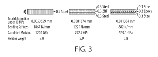
Fig. 3 illustrates a comparison of materials prepared in accordance with one
embodiment of the invention, and control materials; and
Fig. 4 illustrates the weight and cost of various materials, including those
in
accordance with certain embodiments of the invention.
CA 03146374 2022-01-06
WO 2021/007389 PCT/US2020/041322
- 4 -
DETAILED DESCRIPTION
The present disclosure generally relates to systems and methods for
composites,
including carbon fiber-metal composites. In some cases, the composites may be
formed from
one, two, or more layers of metals or other substrates, sandwiching a
plurality of aligned
fibers. The fibers may be substantially aligned, and may be present at
relatively high
densities within the composite. The composites may be prepared, in some
aspects, by
dispersing fibers by neutralizing the electrostatic interactions between the
fibers, for example
using aqueous liquids containing the fibers that are able to neutralize the
electrostatic
interactions that typically occur between the fibers. In some cases, the
fibers may be aligned
using techniques such as shear flow and/or magnetism. Other aspects are
generally directed
to methods of using such composites, kits including such composites, or the
like.
Certain aspects are generally directed to composites for use in various
applications,
for example, requiring relatively high mechanical properties. In some cases,
the composite
may include one, two, three, or more layers, e.g., comprising metals, wood,
ceramics,
polymers, etc., containing or sandwiching other layers, e.g., core layers. In
some cases, the
core layers may comprise short fibers (e.g., less than 5 mm in length), which
may comprise
carbon or other types of fibers. In some cases, the fibers may be oriented or
aligned within
the composite. For example, in some cases, the fibers may be oriented or
aligned
substantially orthogonally to the layer, and in certain embodiments, such
fibers may be used
to enhance the Z-axis mechanical properties of the composites.
In some embodiments, the composite may comprise two layers surrounding an core
layer or material, e.g., to form a "sandwich" structure. The sandwich
composite may thus
comprise a core material that is contained between two skin materials.
Examples include
metallic, wood, composite, ceramic, natural, or composite skin material. The
core material
may be a lower stiffness material, but it can provide thickness to the overall
composite. The
increased gap between the two skin layers may, in some embodiments, increase
the moment
of inertia, which may increases the stiffness of the composite. A core
material with a lower
density compared to the skin may also reduce the overall weight of the
structure in certain
embodiments. The inclusion of a different material as the core can also be
used in some
embodiments, for example, to suppress puncture, vibration, heat, electrical
discharge, etc.
Other properties include those discussed in more detail herein.
In certain embodiments, a composite material may comprise a "core" or
intermediate
layer that includes transversely oriented carbon fiber embedded in a polymer
matrix. The
overall thickness of this composite may be less than one millimeter, or have
other dimensions
CA 03146374 2022-01-06
WO 2021/007389
PCT/US2020/041322
- 5 -
such as those described herein. In some cases, for example, multiples layers
can be
consolidated together to achieve a higher thickness. The core layer may, in
certain
embodiments, provide a high stiffness of carbon fibers in the transverse
direction, e.g., as
described herein. This material also may prevent the displacement of the
matrix polymer in
certain cases, e.g., if the matrix polymer is in a liquid or gelled state.
The core layer can be bonded between two layers, e.g., comprising sheet metal
or
other materials described herein, to create a sandwich composite structure
(e.g., an A/B/A
structure). However, the layers may have different compositions, sizes, etc.,
in some cases
(e.g., forming an A/B/C structure). In addition, in some embodiments, it is
possible to
incorporate the transverse carbon fiber composite in a single-sided structure
(e.g., an A/B
structure), or multiple layers (e.g., A/B/A/B/A, A/B/A/B, etc.). Yet other
embodiments
include any of those described herein.
In certain embodiments, the transverse carbon fiber core may be used to
provide high
transverse stiffness, which results in better relative bending stiffness, and
can allow the cold
forming of various metals, for example, such as HSS and advanced HSS and ultra
HSS and
6000-series and 7000-series aluminum alloy. Such materials may allow for the
weight
reduction of automobiles, or other applications including any of those
discussed herein.
In some cases, a core layer may comprise carbon or other types of fibers that
are
oriented or aligned within the composite. A variety of methods may be used to
produce such
layers, and in some cases, such that the layer has a high fiber volume
content, e.g., while
maintaining dispersion or alignment of the fibers. In some embodiments, the
fibers may be
relatively short, and may comprise carbon or other materials. In some cases,
the fibers may
be homogeneously dispersed in a polymer resin or other slurry. Short fibers
may have high
electrostatic interactions that promotes agglomeration, and the high viscosity
of polymer
resins can prevent consistent dispersion at higher fiber volumes. These
processing defects
thus can cause inconsistent fiber reinforcement and gradients in resin content
in the
composite, which can drastically reduce the performance of the composite.
Accordingly,
certain embodiments as discussed herein can overcome these limitations. In
addition, some
embodiments are generally directed to aligned fibers that maintain high fiber
volume content.
Apart from issues with dispersing the short fibers, prior art methods struggle
with issues such
as low fiber volume fractions, insufficient alignment, or long overall fiber
lengths that risk
issues with fiber breaking.
As an example, in some cases, a composite may be prepared by neutralizing the
electrostatic interactions between fibers, for example using aqueous slurries.
In some cases,
CA 03146374 2022-01-06
WO 2021/007389 PCT/US2020/041322
- 6 -
the slurries containing well-dispersed fibers can be metered onto substrates
such as
thermoplastic films. During metering, the alignment of the fibers can be
controlled, for
example, by using shear flow and/or magnetic alignment. This may be
implemented, for
example, in a roll-to-roll manufacturing process.
For instance, in one set of embodiments, an aqueous liquid comprising suitable
fibers
may be applied to a substrate, e.g., as a coating. The liquid may be selected
to neutralize
electrostatic interactions that typically occur between the fibers, as noted
above. The
substrate can be, for example, a thermoplastic film, or other materials such
as discussed
herein. The fibers may include carbon fibers and/or other fibers. The fibers
are then aligned,
for example, by applying a magnetic field and/or a shear force, e.g., by
applying a suitable
fluid to the liquid applied to the substrate. After alignment, the final
composite may be
formed, for example, by applying heat (e.g., to remove the liquid, for
example, via
evaporation), and/or pressure (e.g., to embed the fibers into the substrate),
and/or introducing
a thermoset layer that can optionally be cured.
The above discussion is a non-limiting example of one embodiment that can be
used
to produce certain types of composites. However, other embodiments are also
possible.
Accordingly, more generally, various aspects are directed to various systems
and methods for
producing various composites and materials, including but not limited to
sandwich or other
layered composites.
For example, certain aspects are generally directed to short-fiber films and
other
composites. In some cases, such composites may comprise a substrate and a
plurality of
discontinuous or short fibers contained or embedded within the composite, or
at least a
portion thereof. In some cases, the plurality of fibers are substantially
aligned or oriented
within the composite.
For example, in some embodiments, a composite may comprise one or more
substrates or layers, such as is disclosed herein, and one or more layers of
discontinuous
fibers, e.g., aligned as discussed herein. For instance, in some cases, a
composite may
comprise a substrate or layer, for example, comprising a metal, wood, a
ceramic, a polymer,
etc., including any of those described herein, and a plurality of
discontinuous fibers (which
may be substantially transversely aligned in some embodiments). More than one
such layer
may be present in the composite. For example, in one embodiment, a composite
may
comprise two layers with a core layer of discontinuous fibers "sandwiched"
between the two
layers, e.g., forming an A/B/A structure. The discontinuous fibers may be
substantially
transversely aligned, e.g., as discussed herein. The two layers may be the
same or different
CA 03146374 2022-01-06
WO 2021/007389 PCT/US2020/041322
- 7 -
(e.g., as in an A/B/C structure). The layers may comprise, for example, a
metal, wood, a
ceramic, a polymer, etc., including any of those described herein. As a non-
limiting example,
in one embodiment, a composite can include two substantially metallic layers
sandwiching a
plurality of discontinuous fibers substantially transversely aligned to the
metallic layers.
It should be understood, however, that in other embodiments, other numbers of
layers
may be present. For example, a composite may contain, 3, 4, 5, or more layers
including
metals, wood, ceramics, polymers, etc., and/or 2, 3, 4, 5, etc. layers of
discontinuous fibers.
Some or all of these layers may comprise substantially transversely aligned
discontinuous
fibers. For example, in one embodiment, the composite may include three layers
of, e.g.,
metals, wood, ceramics, polymers, etc., containing or sandwiching two layers
of
discontinuous fibers. The layers of material and discontinuous fibers may be
the same, e.g.,
forming structures such as A/B/A/B, A/B/A/B/A, A/B/A/B/A/B, A/B/A/B/A/B/A,
etc., or one
or more of these may be different (for example, as in an A/B/C/B structure).
These patterns,
or other patterns, may be extended in still other embodiments.
A variety of materials may be used for the substrate. For example, one or more
layers
within a composite may include layers or substrates comprising polymers,
composite
materials, metals, wood, ceramics, or the like, e.g., as discussed in more
detail below. In
addition, in some cases, a substrate or layer within a composite will comprise
more than one
of these materials, and/or other materials. For instance, a substrate or layer
may comprise a
plurality of polymers, composite materials, metals, wood, ceramics, or the
like. The substrate
or layer may be a solid sheet of material (e.g., sheet metal), or may be
formed from
continuous fibers such as discussed herein. Other structures are also
possible.
In some cases, the composite may be consolidated with another composite layer
to
form a composite structure. If more than one substrate is present in a
composite, the
substrates may independently be the same or different, e.g., the first layer
and the second
layer have substantially the same composition, or different compositions in
some
embodiments. There may be 1, 2, 3, 4, 5, or any other suitable number of
substrates that are
present.
For example, in one set of embodiments, a layer or a substrate of material
within a
composite may comprise a metal. In some cases, at least 50 wt%, at least 60
wt%, at least 70
wt%, at least 75 wt%, at least 80 wt%, at least 85 wt%, at least 90 wt%, or at
least 95% of the
layer may comprise a metal. In certain cases, a layer may be substantially
metallic. In some
embodiments, at least 5%, at least 10%, at least 15%, at least 20%, at least
25%, at least 30%,
at least 40%, at least 50%, at least 50%, at least 70%, at least 80%, at least
90%, at least 95%,
CA 03146374 2022-01-06
WO 2021/007389 PCT/US2020/041322
- 8 -
at least 97%, or at least 99% by volume of the substrate (without the
discontinuous fibers)
may be a metal.
Examples of metals that may be present include, but are not limited to, steel,
aluminum, iron, titanium, or the like. For instance, a layer may comprise at
least 50 wt%, at
least 60 wt%, at least 70 wt%, at least 80 wt%, etc. of a metal such as steel,
aluminum, iron,
titanium, or the like. In some cases, more than one metal may be present in a
layer, e.g., as in
a metal alloy, including any of these and/or other metals. For instance, the
alloy may be an
alloy of steel, aluminum, iron, titanium, or the like. Non-limiting examples
of aluminum
alloys that could be used include 1000-series, 2000-series, 3000-series, 4000-
series, 5000-
.. series, 6000-series, 7000-series, or 8000-series aluminum alloys.
In another set of embodiments, a layer or a substrate comprises a polymer,
such as a
thermoplastic or a thermoset. In some cases, the substrate consists
essentially of a polymer.
In some cases, at least 50 wt%, at least 60 wt%, at least 70 wt%, at least 75
wt%, at least 80
wt%, at least 85 wt%, at least 90 wt%, or at least 95% of the layer may
comprise a polymer.
.. In certain cases, a layer may be substantially polymeric. In some
embodiments, at least 5%,
at least 10%, at least 15%, at least 20%, at least 25%, at least 30%, at least
40%, at least 50%,
at least 50%, at least 70%, at least 80%, at least 90%, at least 95%, at least
97%, or at least
99% by volume of the substrate (without the discontinuous fibers) may be a
polymer.
The substrate may include one or more polymers, including the following
polymers,
.. and may also include other polymers, in addition to or instead of these
polymers. Examples
of suitable polymers for the substrate include, but are not limited to,
polyimide (PI),
polyamide-imide (PAT), polyetheretherketone (PEEK), polyetherketone (PEK),
polyphenylesulfone (PPSU), polyethersulfone (PES), polyetherimide (PEI),
polysulfone
(PSU), polyphenylene sulfide (PPS), polyvinylidene fluoride (PVDF),
.. polytetrafluoroethylene (PTFE), perfluoroalkoxy alkanes (PFA), polyamide 46
(PA46),
polyamide 66 (PA66), polyamide 12 (PA12), polyamide 11 (PA11), polyamide 6
(PA6),
polyamide 6.6 (PA6.6), polyamide 6.6/6 (PA6.6/6), amorphous polyamide (PA6-3-
T),
polyethylene terephthalate (PET), polyphthalamide (PPA), liquid crystal
polymer (LCP),
polycarbonate (PC), polybutylene terephthalate (PBT), polyoxymethylene (POM),
polyphenyl ether (PPE), polymethyl methacrylate (PMMA), polypropylene (PP),
polyethylene (PE), high density polyethylene (HDPE), acrylonitrile styrene
acrylate (ASA),
styrene acrylonitrile (SAN), acrylonitrile butadiene styrene (ABS),
polybenzimidazole (PBI),
polyvinyl chloride (PVC), poly-para-phenylene-copolymer (PPP),
polyacrylonitrile,
CA 03146374 2022-01-06
WO 2021/007389 PCT/US2020/041322
- 9 -
polyethylenimine, polyetherketonetherketoneketone (PEKEKK), ethylene
tetrafluoroethylene
(ETFE), polychlorotrifluoroethylene (PCTFE), and/or polymethylpentene (PMP).
In certain embodiments, a layer or a substrate can comprise a ceramic. In some
cases,
the substrate consists essentially of a ceramic. In some cases, at least 50
wt%, at least 60
.. wt%, at least 70 wt%, at least 75 wt%, at least 80 wt%, at least 85 wt%, at
least 90 wt%, or at
least 95% of the layer may comprise a ceramic. In certain cases, a layer may
be substantially
ceramic. In some embodiments, at least 5%, at least 10%, at least 15%, at
least 20%, at least
25%, at least 30%, at least 40%, at least 50%, at least 50%, at least 70%, at
least 80%, at least
90%, at least 95%, at least 97%, or at least 99% by volume of the substrate
(without the
discontinuous fibers) may be a ceramic.
Non-limiting examples of ceramics include, but are not limited to, siloxane, a
silazane, a carbosilane, or the like. In some cases, the ceramic is a silicon-
containing
ceramic. Other examples of ceramics include, but are not limited to, alumina,
silicon carbide,
aluminum nitride, silicon nitride, zirconia, mullite, hafnium diboride,
zirconium diboride,
hafnium nitride, zirconium nitride, titanium carbide, titanium nitride,
thorium dioxide,
tantalum carbide, etc.
Certain embodiments are generally directed to composites comprising substrates
formed from continuous fibers, and containing a plurality of discontinuous
fibers. The fibers
may include, for example, one or more layers comprising polymers, metals,
wood, ceramics,
or the like. The continuous fibers generally have a length that on average is
substantially
longer than the cross-sectional dimension of the discontinuous fibers. For
instance, the
continuous fibers may have an average length that is greater than 10, greater
than 30, greater
than 50, greater than 100, greater than 300, greater than 500, or greater than
1,000 times the
cross-sectional dimension of the discontinuous fibers. In some embodiments,
the continuous
.. fibers have an average aspect ratio (e.g., of length to diameter or average
cross-sectional
dimension) of at least 3, at least 5, at least 10, at least 30, at least 50,
at least 100, at least 300,
at least 500, at least 1,000, etc. Additionally, in certain cases, the
continuous fibers may have
an average length of at least 5 mm, at least 1 cm, at least 3 cm, at least 5
cm, or at least 10
cm. Longer average lengths are also possible in some instances.
The continuous fibers may be woven together (e.g. bidirectional,
multidirectional,
quasi-isotropic, etc.), and/or non-woven (e.g., unidirectional, veil, mat,
etc.). In certain
embodiments, at least some of the continuous fibers are substantially
parallel, and/or
orthogonally oriented relative to each other, although other configurations of
continuous
fibers are also possible. In certain embodiments, the continuous fibers may
together define a
CA 03146374 2022-01-06
WO 2021/007389
PCT/US2020/041322
- 10 -
fabric or other substrate, e.g., a textile, a tow, a filament, a yarn, a
strand, or the like. In some
cases, the substrate may have one orthogonal dimension that is substantially
less than the
other orthogonal dimensions (i.e., the substrate may have a thickness).
The continuous fibers forming the substrate may comprise any of a wide variety
of
materials, and one type or more than one type of fiber may be present within
the substrate.
Non-limiting examples include carbon, basalt, silicon carbide, aramid,
zirconia, nylon, boron,
alumina, silica, borosilicate, mullite, cotton, or any other natural or
synthetic fibers.
The continuous fibers may have any suitable average diameter. For example, the
continuous fibers may have an average diameter of at least 10 micrometers, at
least 20
micrometers, at least 30 micrometers, at least 50 micrometers, at least 100
micrometers, at
least 200 micrometers, at least 300 micrometers, at least 500 micrometers, at
least 1 mm, at
least 2 mm, at least 3 mm, at least 5 mm, at least 1 cm, at least 2 cm, at
least 3 cm, at least 5
cm, at least 10 cm, etc. In certain embodiments, the continuous fibers may
have an average
diameter of no more than 10 cm, no more than 5 cm, no more than 3 cm, no more
than 2 cm,
no more than 1 cm, no more than 5 mm, no more than 3 mm, no more than 2 mm, no
more
than 1 mm, no more than 500 micrometers, no more than 300 micrometers, no more
than 200
micrometers, no more than 100 micrometers, no more than 50 micrometers, no
more than 30
micrometers, no more than 20 micrometers, no more than 10 micrometers, etc.
Combinations
of any of these are also possible. For example, the continuous fibers may have
an average
diameter of between 10 micrometers and 100 micrometers, between 50 micrometers
and 500
micrometers, between 100 micrometers and 5 mm, etc.
The continuous fibers may also have any suitable average length. For example,
the
continuous fibers may have an average length of at least about 0.5 cm, at
least 1 cm, at least 2
cm, at least 3 cm, at least 5 cm, at least 10 cm, etc. In certain embodiments,
the continuous
fibers may have an average diameter of no more than 10 cm, no more than 5 cm,
no more
than 3 cm, no more than 2 cm, no more than 1 cm, no more than 0.5 cm, or the
like.
Combinations of any of these are also possible; for example, the continuous
fibers may have
an average length of between 1 cm and 10 cm, between 10 cm and 100 cm, etc.
In some instances, the continuous fibers may comprise a relatively large
portion of the
composite. For example, in certain embodiments, the continuous fibers may
comprise at least
1%, at least 2%, at least 3%, at least 4%, at least 5%, at least 7%, at least
10%, at least 15%,
at least 20%, at least 25%, at least 30%, at least 35%, at least 40%, at least
45%, at least 50%,
at least 55%, at least 60%, at least 65%, at least 70%, at least 75%, at least
80%, at least 85%,
at least 90%, at least 95%, or at least 97% of the mass of the composite. In
some cases, the
CA 03146374 2022-01-06
WO 2021/007389
PCT/US2020/041322
- 11 -
continuous fibers comprise no more than 97%, no more than 95%, no more than
93%, no
more than 91%, no more than 90%, no more than 85%, no more than 80%, no more
than
70%, no more than 60%, no more than 50%, no more than 40%, no more than 30%,
no more
than 20%, or no more than 10% of the mass of the composite. Combinations of
any of these
are also possible.
In some embodiments, a layer or a substrate comprises a material such as a
thermoset,
thermoplastic, and/or a vitrimer. Additional non-limiting examples of
materials that may be
present in a layer or substrate binders include an epoxy, polyester, vinyl
ester,
polyethylenimine, polyetherketoneketone, polyaryletherketone, polyether ether
ketone,
polyphenylene sulfide, polyethylene terephthalate, a polycarbonates,
poly(methyl
methacrylate), acrylonitrile butadiene styrene, polyacrylonitrile,
polypropylene, polyethylene,
nylon, a silicone rubber, polyvinylidene fluoride, styrene butadiene rubber,
or a pre-ceramic
monomer, a siloxane, a silazane, or a carbosilane. In some cases, a layer or
substrate may
comprise a covalent network polymer prepared from an imine-linked oligomer and
an
independent crosslinker comprising a reactive moiety. Non-limiting examples of
reactive
moieties include epoxy, isocyanate, bismaleimide, sulfide, polyurethane,
anhydride, and/or
polyester. Examples of vitrimers include, but are not limited to, epoxy resins
based on
diglycidyl ether of bisphenol A, aromatic polyesters, polylactic acid
(polylactide),
polyhydroxyurethanes, epoxidized soybean oil with citric acid, polybutadiene,
etc.
In addition, as mentioned, a substrate or layer within a composite may
comprise more
than one of these materials, and/or other materials, in other embodiments. For
instance, a
substrate or layer may comprise a plurality of polymers, composite materials,
metals, wood,
ceramics, or the like. If more than one substrate or layer is present within a
composite, these
may independently be the same or different.
A composite may also contain one or more discontinuous fibers in some aspects.
These may be present anywhere in the composite, for example, contained or
embedded
within the substrate, or at least a portion thereof. In some cases, the
discontinuous fibers may
be substantially aligned within the composite, e.g., forming a layer within
the composite. In
some cases, at least 50%, at least 70%, at least 80%, at least 90%, at least
95%, at least 97%,
or at least 99% by volume of the substrate may contain discontinuous fibers.
The discontinuous fibers may be formed or include any of a wide variety of
materials,
and one or more than one type of material may be present. For example, the
discontinuous
fibers may comprise materials such as carbon (e.g., carbon fibers), basalt,
silicon carbide,
silicon nitride, aramid, zirconia, nylon, boron, alumina, silica,
borosilicate, mullite, nitride,
CA 03146374 2022-01-06
WO 2021/007389
PCT/US2020/041322
- 12 -
boron nitride, graphite, glass, a polymer (including any of those described
herein), or the like.
The discontinuous fibers may include any natural and/or any synthetic
material, and may be
magnetic and/or non-magnetic.
The discontinuous fibers, in some embodiments, may be at least substantially
aligned
within the composite. Methods for aligning discontinuous fibers are discussed
in more detail
herein. Various alignments are possible, and in some cases, can be determined
optically or
microscopically, e.g. Thus, in some cases, the alignment may be determined
qualitatively.
However, it should be understood that the alignment need not be perfect. In
some cases, at
least 5%, at least 10%, at least 25%, at least 50%, at least 75%, at least
85%, at least 90%, or
at least 95% of the fibers within a composite may exhibit an alignment that is
within 20 ,
within 15 , within 10 , or within 5 of the average alignment of the plurality
of the fibers,
e.g., within a sample of the composite. In some cases, the average alignment
of the fibers
may be oriented to be at least 60 , at least 65 , at least 70 , at least 75 ,
at least 85 , or at least
87 relative to the plane of the substrate at that location.
Without wishing to be bound by any theory, it is believed that alignment of
the
discontinuous fibers substantially orthogonal to the substrate may serve to
provide
reinforcement of the substrate. This may improve the strength of the
substrate, e.g., when
subjected to forces in different directions. For instance, fibers within the
substrate may run in
substantially orthogonal directions in 3 dimensions, thereby providing
strength to the
substrate regardless of the direction of force that is applied. The fibers may
also limit
degradation of the surface, e.g., with interlaminar micro-cracks, through-ply
fissures, or the
like. In addition, in some embodiments, the fibers may enhance other
properties of the
substrate, e.g., electrical and/or thermal properties within the composite, in
addition to or
instead of its mechanical properties.
While others have suggested packing fibers in a substrate, it is believed that
higher
fiber volume fractions were previously unachievable, e.g., due to higher
electrostatic
interactions that cause fiber agglomeration, and/or higher viscosities of
polymer resins that
can prevent consistent dispersion. Accordingly, certain embodiments are
generally directed
to fiber volume fractions (e.g., of substantially aligned fibers such as those
discussed herein)
.. of at least 40% fiber volume, at least 45% fiber volume, at least 50% fiber
volume, at least
55% fiber volume, at least 60% fiber volume, at least 65% fiber volume, at
least 70% fiber
volume, etc.
A variety of techniques may be used to align the discontinuous fibers in
various
embodiments, including magnetic fields, shear flow, or the like, as are
discussed in more
CA 03146374 2022-01-06
WO 2021/007389
PCT/US2020/041322
- 13 -
detail below. As a non-limiting example, magnetic particles, including those
discussed
herein, can be attached to the fibers, and a magnetic field may then be used
to manipulate the
magnetic particles. For instance, the magnetic field may be used to move the
magnetic
particles into the substrate, and/or to align the discontinuous fibers within
the substrate. The
magnetic field may be constant or time-varying (e.g., oscillating), for
instance, as is discussed
herein. For example, an applied magnetic field may have a frequency of 1 Hz to
500 Hz and
an amplitude of 0.01 T to 10 T. Other examples of magnetic fields are
described in more
detail below.
In some cases, the discontinuous fibers may have an average length, or
characteristic
dimension, of at least 1 nm, at least 3 nm, at least 5 nm, at least 10 nm, at
least 30 nm, at least
50 nm, at least 100 nm, at least 300 nm, at least 500 nm, at least 1
micrometer, at least 3
micrometers, at least 5 micrometers, at least 10 micrometers, at least 20
micrometers, at least
30 micrometers, at least 50 micrometers, at least 100 micrometers, at least
200 micrometers,
at least 300 micrometers, at least 500 micrometers, at least 1 mm, at least 2
mm, at least 3
mm, at least 5 mm, at least 10 mm, at least 15 mm, etc. In certain
embodiments, the
discontinuous fibers may have an average length, or characteristic dimension,
of no more
than 5 cm, no more than 3 cm, no more than 2 cm, no more than 1.5 cm, no more
than 1 cm,
no more than 5 mm, no more than 3 mm, no more than 2 mm, no more than 1 mm, no
more
than 500 micrometers, no more than 300 micrometers, no more than 200
micrometers, no
more than 100 micrometers, no more than 50 micrometers, no more than 30
micrometers, no
more than 20 micrometers, no more than 10 micrometers, no more than 5
micrometers, no
more than 3 micrometers, no more than 1 micrometers, no more than 500 nm, no
more than
300 nm, no more than 100 nm, no more than 50 nm, no more than 30 nm, no more
than 10
nm, no more than 5 nm, etc. Combinations of any of these are also possible.
For example,
the discontinuous fibers within a composite may have an average length of
between 1 mm
and 5 mm.
In addition, the discontinuous fibers may also have any suitable average
diameter.
For instance, the discontinuous fibers may have an average diameter of at
least 10
micrometers, at least 20 micrometers, at least 30 micrometers, at least 50
micrometers, at
least 100 micrometers, at least 200 micrometers, at least 300 micrometers, at
least 500
micrometers, at least 1 mm, at least 2 mm, at least 3 mm, at least 5 mm, at
least 1 cm, at least
2 cm, at least 3 cm, at least 5 cm, at least 10 cm, etc. In certain
embodiments, the
discontinuous fibers may have an average diameter of no more than 10 cm, no
more than 5
cm, no more than 3 cm, no more than 2 cm, no more than 1 cm, no more than 5
mm, no more
CA 03146374 2022-01-06
WO 2021/007389
PCT/US2020/041322
- 14 -
than 3 mm, no more than 2 mm, no more than 1 mm, no more than 500 micrometers,
no more
than 300 micrometers, no more than 200 micrometers, no more than 100
micrometers, no
more than 50 micrometers, no more than 30 micrometers, no more than 20
micrometers, no
more than 10 micrometers, etc. Combinations of any of these are also possible.
For example,
the discontinuous fibers may have an average diameter of between 10
micrometers and 100
micrometers, between 50 micrometers and 500 micrometers, between 100
micrometers and 5
mm, etc.
In certain embodiments, the discontinuous fibers may have a length that is at
least 10
times or at least 50 times its thickness or diameter, on average. In some
cases, the fibers
.. within a composite may have an average aspect ratio (ratio of fiber length
to diameter or
thickness) of at least 3, at least 5, at least 10, at least 30, at least 50,
at least 100, at least 300,
at least 500, at least 1,000, at least 3,000, at least 5,000, at least 10,000,
at least 30,000, at
least 50,000, or at least 100,000. In some cases, the average aspect ratio may
be less than
100,000, less than 50,000, less than 30,000, less than 10,000, less than
5,000, less than 3,000,
.. less than 1,000, less than 500, less than 300, less than 100, less than 50,
less than 30, less than
10, less than 5, etc. Combinations of any of these are also possible in some
cases; for
instance, the aspect ratio may be between 5, and 100,000.
In some instances, the discontinuous fibers may comprise a relatively large
portion of
the composite. For example, in certain embodiments, the discontinuous fibers
may comprise
at least 1%, at least 2%, at least 3%, at least 4%, at least 5%, at least 7%,
at least 10%, at least
15%, at least 20%, at least 25%, at least 30%, at least 35%, at least 40%, at
least 45%, at least
50%, at least 55%, at least 60%, at least 65%, at least 70%, at least 75%, at
least 80%, at least
85%, at least 90%, at least 95%, or at least 97% of the mass or volume of the
composite. In
some cases, the discontinuous fibers comprise no more than 97%, no more than
95%, no
more than 90%, no more than 85%, no more than 80%, no more than 70%, no more
than
60%, no more than 50%, no more than 40%, no more than 30%, no more than 20%,
or no
more than 10% of the mass or volume of the composite. Combinations of any of
these are
also possible.
At least some of the discontinuous fibers may be uncoated. In some cases,
however,
some or all of the discontinuous fibers may be coated. The coating may be
used, for
example, to facilitate the adsorption or binding of particles, such as
magnetic particles, onto
the fibers, or for other reasons.
As one example, at least some of the discontinuous fibers are coated with
sizing.
Some examples of sizings include, but are not limited to, polypropylene,
polyurethane,
CA 03146374 2022-01-06
WO 2021/007389
PCT/US2020/041322
- 15 -
polyamide, phenoxy, polyimide, epoxy, or the like. These sizings can be
introduced into the
slurry, for example, as a solution, dispersion, emulsion, etc. As other
examples, the fibers
may be coated with a surfactant, a silane coupling agent, an epoxy, glycerine,
polyurethane,
an organometallic coupling agent, or the like. Non-limiting examples of
surfactants include
oleic acid, sodium dodecyl sulfate, sodium lauryl sulfate, etc. Non-limiting
examples of
silane coupling agents include amino-, benzylamino-, chloropropyl-, disulfide-
, epoxy-,
epoxy/melamine-, mercapto-, methacrylate-, tertasulfido-, ureido-, vinyl-,
isocynate-, and
vinly-benzyl-amino-based silane coupling agents. Non-limiting examples of
organometallic
coupling agents include aryl- and vinyl-based organometallic coupling agents.
As mentioned, in one set of embodiments, at least some of the discontinuous
fibers
may be carbon fibers. The carbon fibers may be aligned in a magnetic field
directly or
indirectly, e.g., using magnetic particles such as those discussed herein. For
instance, some
types of carbon fibers are diamagnetic, and can be directly moved using an
applied magnetic
field. Thus, certain embodiments are directed to fibers or composites that are
substantially
free of paramagnetic or ferromagnetic materials could still be aligned using
an external
magnetic field. For example, if any paramagnetic or ferromagnetic materials
are present,
they may form less than 5%, less than 1%, less than 0.5%, less than 0.3%, less
than 0.1%,
less than 0.05%, less than 0.03%, less than 0.01%, less than 0.005%, less than
0.003%, or less
than 0.001% (by mass) of the material.
A variety of carbon fibers may be obtained commercially, including diamagnetic
carbon fibers. In some cases, carbon fibers can be produced from polymer
precursors such as
polyacrylonitrile (PAN), rayon, pitch, or the like. In some cases, carbon
fibers can be spun
into filament yarns, e.g., using chemical or mechanical processes to initially
align the
polymer atoms in a way to enhance the final physical properties of the
completed carbon
fibers. Precursor compositions and mechanical processes used during spinning
filament
yarns may vary. After drawing or spinning, the polymer filament yarns can be
heated to
drive off non-carbon atoms (carbonization or pyrolization), to produce final
carbon fiber. In
some embodiments, such techniques may be used to produce carbon fiber with
relatively high
carbon content, e.g., at least 90%, or other contents as described herein.
Non-limiting examples of carbon fibers include, for instance, pitch- and/or
polymer-
based (e.g. ex-PAN or ex-Rayon) variants, including those commercially-
available. In some
cases, these may include intermediate/standard modulus (greater than 200 GPa)
carbon fibers,
high modulus (greater than 300 GPa), or ultra-high modulus (greater than 500
GPa) carbon
fibers.
CA 03146374 2022-01-06
WO 2021/007389
PCT/US2020/041322
- 16 -
In one set of embodiments, the carbon fibers have a relatively high carbon
content.
Without wishing to be bound by any theory, it is believed that such fibers may
exhibit
diamagnetic properties that allows them to be oriented with low-energy
magnetic fields. In
general, diamagnetism is the repulsion of a material to an applied magnetic
field by
generation of an induced magnetic field that is opposite in direction to the
applied magnetic
field. A material is typically categorized as diamagnetic if it lacks
noticeable paramagnetic
or ferromagnet contributions to the overall magnetic response. In many cases,
the magnetic
response of diamagnetic materials is very weak and negligible. However,
relatively high
magnetic fields can induce a noticeable physical response in such diamagnetic
materials.
Thus, in some cases, carbon fibers exhibiting relatively highly-oriented
molecular
structures may exhibit anisotropic, high-diamagnetism diamagnetic properties.
Such
diamagnetic properties may allow them to be oriented with relatively weak
magnetic fields,
such as is described herein. For example, in one set of embodiments, an
applied magnetic
field may generate a strong induced magnetic field in the C-C bonds of a
carbon fiber in the
opposite direction of the applied magnetic field. Certain types of carbon
fibers may possess a
high degree of C-C bonds parallel to the in-fiber direction, which may create
an anisotropic
diamagnetic response. Thus, such carbon fibers can be subjected to a magnetic
torque that is
neutralized when the carbon fiber aligns fully-parallel to the applied
magnetic field.
Accordingly, by applying a suitable magnetic field, the carbon fibers may be
aligned due to
such diamagnetic properties. This response may be sufficient to overcome
gravitational,
viscous, and/or interparticle steric effects.
For instance, in certain embodiments, the carbon fibers may have a carbon
content of
greater than 80%, greater than 90%, greater than 92%, greater than 94%,
greater than 95%,
greater than 96%, greater than 97%, greater than 98% greater than 99%, or
greater than
99.5% by mass. Such carbon fibers may be obtained commercially in some cases.
For
example, the carbon fibers may be produced pyrolytically e.g., by "burning" or
oxidizing
other components that can be removed (e.g., by turning into a gas), leaving
behind a carbon
fiber with a relatively high carbon content. Other methods of making carbon
fibers are also
possible, e.g., as discussed in detail herein.
The carbon fibers may also exhibit substantial alignment of the C-C bonds
within the
carbon fibers in some instances. For instance, at least 50%, at least 60%, at
least 70%, at
least 75%, at least 80%, at least 85%, at least 90%, or at least 95% of the
carbon fibers may
exhibit substantial alignment of the C-C bonds. Such alignment may be
determined, for
CA 03146374 2022-01-06
WO 2021/007389
PCT/US2020/041322
- 17 -
example, using wide angle x-ray diffraction (WAXD), or other techniques known
to those of
ordinary skill in the art.
In one set of embodiments, the carbon fibers may have a relatively high
modulus
(tensile modulus, which is a measure of stiffness). Typically, higher modulus
fibers are
stiffer and lighter than low modulus fibers. Carbon fibers typically have a
higher modulus
when force is applied parallel to the fibers, i.e., the carbon fibers are
anisotropic. In some
embodiments, the carbon fibers may have a modulus (e.g., when force is applied
parallel to
the fibers) of at least 100 GPa, at least 200 GPa, at least 300 GPa, at least
400 GPa, at least
500 GPa, at least 600 GPa, at least 700 GPa, etc. It is believed that more
flexible carbon
fibers may exhibit less alignment, i.e., carbon fibers having a low modulus
may have subtle
physical responses to magnetic fields, or have no response, rather than align
within an applied
magnetic field.
In one set of embodiments, the carbon fibers may exhibit an anisotropic
diamagnetic
response when free-floating within a liquid (e.g., water, oil, polymer resin,
polymer melt,
metal melt, an alcohol such as ethanol, or another volatile organic compound),
and a
magnetic field is applied. For example, in some cases, the carbon fibers may
align when a
suitable magnetic field is applied, i.e., indicative of a diamagnetic
response. In some cases,
the magnetic field may be at least 100 mT, at least 200 mT, at least 300 mT,
at least 500 mT,
at least 750 mT, at least 1 T, at least 1.5 T, at least 2 T, at least 3 T, at
least 4 T, at least 5 T,
at least 10 T, etc. In some cases, at least 30%, at least 40%, at least 50%,
at least 60%, at
least 70%, at least 80%, or at least 90%, of the free-floating carbon fibers
within the liquid
may exhibit alignment when a suitable magnetic field is applied.
Typically, a carbon fiber has a shape such that one orthogonal dimension
(e.g., its
length) is substantially greater than its other two orthogonal dimensions
(e.g., its width or
thickness). The fiber may be substantially cylindrical in some cases. As
mentioned, the
carbon fibers may be relatively stiff, in some instances; however, a carbon
fiber need not be
perfectly straight (e.g., its length may still be determined along the fiber
itself, even if it is
curved).
In one set of embodiments, the carbon fiber may have a dimension (e.g., a
characteristic dimension) that is substantially the same, or smaller, than the
thickness of the
substrate. For example, at least some carbon fibers within a composite may
have an average
length that substantially spans the thickness of the substrate. However, in
other cases, the
characteristic dimension of the carbon fiber may be greater than the
thickness.
CA 03146374 2022-01-06
WO 2021/007389
PCT/US2020/041322
- 18 -
As mentioned, in one set of embodiments, particles such as magnetic particles
may be
added, for example, to align the discontinuous fibers, or for other
applications. The particles
may be adsorbed or otherwise bound to at least some of the discontinuous
fibers. In some
cases, the particles may coat some or all of the discontinuous fibers and/or
the continuous
fibers. This may be facilitated by a coating of material as discussed herein,
although a
coating is not necessarily required to facilitate the adsorption of the
particles.
If the particles are magnetic, the particles may comprise any of a wide
variety of
magnetically susceptible materials. For example, the magnetic materials may
comprise one
or more ferromagnetic materials, e.g., containing iron, nickel, cobalt,
alnico, oxides of iron,
nickel, cobalt, rare earth metals, or an alloy including two or more of these
and/or other
suitable ferromagnetic materials. In some cases, the magnetic particles may
have a relative
permeability of at least 2, at least 5, at least 10, at least 20, at least 40,
at least 100, at least
200, at least 500, at least 1,000, at least 2,000, at least 5,000, or at least
10,000.
However, it should be understood that not all of the particles are necessarily
magnetic.
In some cases, non-magnetic particles may be used, e.g., in addition to and/or
instead of
magnetic particles. Non-limiting examples of nonmagnetic particles include
glass, polymer,
metal, or the like.
The particles (if present) may be spherical or non-spherical, and may be of
any
suitable shape or size. The particles may be relatively monodisperse or come
in a range of
sizes. In some cases, the particles may have a characteristic dimension, on
average, of at
least 10 micrometers, at least 20 micrometers, at least 30 micrometers, at
least 50
micrometers, at least 100 micrometers, at least 200 micrometers, at least 300
micrometers, at
least 500 micrometers, at least 1 mm, at least 2 mm, at least 3 mm, at least 5
mm, at least 1
cm, at least 1.5 cm, at least 2 cm, at least 3 cm, at least 5 cm, at least 10
cm, etc. The
particles within the composite may also have an average characteristic
dimension of no more
than 10 cm, no more than 5 cm, no more than 3 cm, no more than 2 cm, no more
than 1.5 cm,
no more than 1 cm, no more than 5 mm, no more than 3 mm, no more than 2 mm, no
more
than 1 mm, no more than 500 micrometers, no more than 300 micrometers, no more
than 200
micrometers, no more than 100 micrometers, no more than 50 micrometers, no
more than 30
micrometers, no more than 20 micrometers, no more than 10 micrometers, etc.
Combinations
of any of these are also possible. For example, the particles may exhibit a
characteristic
dimension of or between 100 micrometer and 1 mm, between 10 micrometer and 10
micrometer, etc. The characteristic dimension of a nonspherical particle may
be taken as the
diameter of a perfect sphere having the same volume as the nonspherical
particle.
CA 03146374 2022-01-06
WO 2021/007389
PCT/US2020/041322
- 19 -
In some embodiments, the particles (including magnetic and/or non-magnetic
particles) may comprise a relatively large portion of the composite. For
example, in certain
embodiments, the particles may comprise at least 1%, at least 2%, at least 3%,
at least 4%, at
least 5%, at least 7%, at least 10%, at least 15%, at least 20%, at least 25%,
at least 30%, at
least 35%, at least 40%, at least 45%, at least 50%, at least 55%, at least
60%, at least 65%, at
least 70%, at least 75%, at least 80%, at least 85%, at least 90%, at least
95%, or at least 97%
of the volume of the composite. In some cases, the particles comprise no more
than 97%, no
more than 95%, no more than 90%, no more than 85%, no more than 80%, no more
than
70%, no more than 60%, no more than 50%, no more than 45%, no more than 40%,
no more
than 35% no more than 30%, no more than 25%, no more than 20%, no more than
15%, no
more than 10%, no more than 7%, no more than 5%, no more than 4%, no more than
3%, no
more than 2%, or no more than 1% of the volume of the composite. Combinations
of any of
these are also possible.
As discussed, one set of embodiments are generally directed to composite
materials.
In some cases, the composite is generally planar. However, it should be
understood that such
a substrate need not be a mathematically-perfect planar structure (although it
can be); for
instance, the substrate may also be deformable, curved, bent, folded, rolled,
creased, or the
like. As examples, the substrate may have an average thickness of at least
about 0.1
micrometers, at least about 0.2 micrometers, at least about 0.3 micrometers,
at least about 0.5
micrometers, at least about 1 micrometer, at least about 2 micrometers, at
least about 3
micrometers, at least about 5 micrometers, at least about 10 micrometers, at
least about 30
micrometers, at least about 50 micrometers, at least about 100 micrometers, at
least about 300
micrometers, at least about 500 micrometers, at least about 1 mm, at least
about 2 mm, at
least about 3 mm, at least about 5 mm, at least about 1 cm, at least about 3
cm, at least about
5 cm, at least about 10 cm, at least about 30 cm, at least about 50 cm, at
least about 100 cm,
etc. In certain instances, the average thickness may be less than 100 cm, less
than 50 cm, less
than 30 cm, less than 10 cm, less than 5 cm, less than 3 cm, less than 1 cm,
less than 5 mm,
less than 2 mm, less than 3 mm, less than 1 mm, less than 500 micrometers,
less than 300
micrometers, less than 100 micrometers, less than 50 micrometers, less than 30
micrometers,
less than 10 micrometers, less than 5 micrometers, less than 3 micrometers,
less than 1
micrometers, less than 0.5 micrometers, less than 0.3 micrometers, or less
than 0.1
micrometers. Combinations of any of these are also possible in certain
embodiments. For
instance, the average thickness may be between 0.1 and 5,000 microns, between
10 and 2,000
microns, between 50 and 1,000 microns, or the like. The thickness may be
uniform or non-
CA 03146374 2022-01-06
WO 2021/007389
PCT/US2020/041322
- 20 -
uniform across the substrate. Also, the substrate may be rigid (e.g., as
discussed herein), or
may be deformable in some cases.
In one set of embodiments, a binder is also present within the composite,
e.g., which
may be used to bind the continuous fibers and the discontinuous fibers, e.g.,
within the
composite. For example, the binder may facilitate holding the continuous
fibers and the
discontinuous fibers in position within the composite. However, it should be
understood that
the binder is optional and not required in all cases. In some cases, the
binder may comprise a
resin. The binder may include, for example, a thermoset, thermoplastic, and/or
a vitrimer. In
certain embodiments, the binder may comprise a thermoplastic solution, a
thermoplastic melt,
thermoplastic pellets, a thermoset resin, a volatile compound such as a
volatile organic
compound, water, or an oil. Additional non-limiting examples of binders
include an epoxy,
polyester, vinyl ester, polyethylenimine, polyetherketoneketone,
polyaryletherketone,
polyether ether ketone, polyphenylene sulfide, polyethylene terephthalate, a
polycarbonates,
poly(methyl methacrylate), acrylonitrile butadiene styrene, polyacrylonitrile,
polypropylene,
polyethylene, nylon, a silicone rubber, polyvinylidene fluoride, styrene
butadiene rubber, or a
pre-ceramic monomer, a siloxane, a silazane, or a carbosilane. In some cases,
a binder may
comprise a covalent network polymer prepared from an imine-linked oligomer and
an
independent crosslinker comprising a reactive moiety. Non-limiting examples of
reactive
moieties include epoxy, isocyanate, bismaleimide, sulfide, polyurethane,
anhydride, and/or
polyester. Examples of vitrimers include, but are not limited to, epoxy resins
based on
diglycidyl ether of bisphenol A, aromatic polyesters, polylactic acid
(polylactide),
polyhydroxyurethanes, epoxidized soybean oil with citric acid, polybutadiene,
etc. The
binder may also include mixtures including any one or more of these materials
and/or other
materials, in certain embodiments.
In some embodiments, the binder may comprise at least 1%, at least 2%, at
least 3%,
at least 4%, at least 5%, at least 7%, at least 10%, at least 15%, at least
20%, or at least 25%
of the mass of the composite, and/or no more than 25%, no more than 20%, no
more than
15%, no more than 10%, no more than 7%, no more than 5%, no more than 4%, no
more than
3%, no more than 2%, or no more than 1% of the mass of the composite.
Composites may be used in a wide variety of applications. As non-limiting
examples,
composites may be used in diverse applications such as reinforcement for
pressure vessels,
components for wind turbines, shims used in jacking heavy structures, sporting
equipment
(e.g., golf clubs, tennis rackets, bike frames, etc.), building or
construction materials,
laminates or encapsulants for electronic devices, battery components, or
panels for vehicles
CA 03146374 2022-01-06
WO 2021/007389
PCT/US2020/041322
- 21 -
such as automobiles, aircraft, marine vehicles, or spacecraft. In some cases,
the composites
may be useful for eliminating or reducing stress concentrations or
delamination within
materials, stiffening materials, eliminating or reducing surface wear,
dissipating electrical
shocks, transmitting electrical signals, attenuating or transmitting
electromagnetic waves,
dissipating thermal shocks, eliminating or reducing thermal gradients, as
components for
energy storage applications, or as components for carbon fibers or ceramic
matrixes.
Another aspect is generally directed to systems and methods for making
composites
such as those described herein. In one set of embodiments, composites can be
prepared from
a liquid. The liquid may be, for example, a slurry, a solution, an emulsion,
or the like. The
liquid may contain discontinuous fibers such as discussed herein, and may be
applied to a
substrate. The fibers may then be aligned as discussed herein, and the liquid
may be then be
removed to create a fiber-containing substrate. After alignment, the final
composite may be
formed, for example, by applying heat (for example, to remove the liquid),
and/or pressure
(for example, to embed the fibers into the substrate). In some cases, the
composite can be set
or hardened, e.g., with a binder, which may be used to immobilize or fix the
discontinuous
agents within the substrate. The composite may be relatively stiff or flexible
in various
embodiments. For instance, in one set of embodiments, the composite may be
wound into a
continuous roll. In some cases, a liquid, such as a slurry, may be used. The
slurry may
include the discontinuous fibers and optionally, magnetic particles or other
components to be
applied to the substrate.
In one set of embodiments, the liquid is able to neutralize the electrostatic
interactions
between the discontinuous fibers, for example using aqueous liquids. This may
be useful, for
example, to allow the discontinuous fibers to be dispersed within the liquid
at relatively high
fiber volumes without agglomeration. In some cases, surfactants and/or
alcohols can be
introduced into the slurry to reduce electrostatic interactions between the
fibers. High shear
mixing and flow also may help reduce agglomeration/flocculation in certain
cases.
In some embodiments, the liquid phase may include, for example, a
thermoplastic or a
thermoset, e.g., a thermoplastic solution, thermoplastic melt, thermoset,
volatile organic
compound, water, or oil. Non-limiting examples of thermosets include
polyethylenimine,
polyetherketoneketone, polyaryletherketone, polyether ether ketone,
polyphenylene sulfide,
polyethylene terephthalate, a polycarbonates, poly(methyl methacrylate),
acrylonitrile
butadiene styrene, polyacrylonitrile, polypropylene, polyethylene, nylon,
polyvinylidene
fluoride, phenolics, epoxies, bismaleimides, cyanate esters, polyimides, etc.
Non-limiting
examples of elastomers include silicone rubber and styrene butadiene rubber,
etc. Non-
CA 03146374 2022-01-06
WO 2021/007389
PCT/US2020/041322
- 22 -
limiting examples of thermoplastics include epoxy, polyester, vinyl ester,
polycarbonates,
polyamides (e.g., nylon, PA-6, PA-12, etc.), polyphenylene sulfide,
polyetherimide,
polyetheretherketone, polyetherketoneketone, etc. Non-limiting examples of
ceramic
monomers include a siloxane, a silazane, or a carbosilane, etc. In some cases,
for example,
one or more of these may be added to assist in homogenously dispersing the
discontinuous
fibers within the liquid. Examples of volatile organic compounds include, but
are not limited
to, isopropanol, butanol, ethanol, acetone, toluene, or xylenes.
Any suitable amount of discontinuous fiber may be present in the slurry or
other
liquid. For instance, at least 10%, at least 15%, at least 20%, at least 25%,
at least 30%, at
least 35%, at least 40%, at least 45%, at least 50%, at least 55%, at least
60%, at least 65%, at
least 70%, at least 75%, or at least 80% of the volume of the slurry may be
discontinuous
fiber. In some cases, no more than 85%, no more than 80%, no more than 75%, no
more than
70%, no more than 65%, no more than 60%, no more than 55%, no more than 50%,
no more
than 45%, no more than 40%, no more than 35%, no more than 30%, no more than
25%, no
more than 20%, no more than 15%, or no more than 10% may be discontinuous
fiber.
Combinations of any of these are also possible in some cases. For example, a
slurry or other
liquid may contain between 70% and 80%, between 75% and 85%, between 50% and
90%,
etc. discontinuous fiber.
After preparation of the slurry or other liquid, it may be applied to or
exposed to the
substrate. Any suitable method may be used to apply the slurry or other liquid
to the
substrate. As non-limiting examples, the liquid may be poured, coated,
sprayed, or painted
onto the substrate, or the substrate may be immersed partially or completely
within the liquid.
The liquid may be used to wet, coat, and/or surround the substrate.
A magnetic field may be applied to manipulate the discontinuous fibers,
directly or
indirectly, as discussed herein, according to one set of embodiments. Any
suitable magnetic
field may be applied. In some cases, the magnetic field is a constant magnetic
field. In other
cases, the magnetic field may be time-varying; for example, the magnetic field
may oscillate
or periodically change in amplitude and/or direction, e.g., to facilitate
manipulation of the
discontinuous agents. The oscillation may be sinusoidal or another repeating
waveform (e.g.,
square wave or sawtooth). The frequency may be, for example, at least 0.1 Hz,
at least 0.3
Hz, at least 0.5 Hz, at least 1 Hz, at least 3 Hz, at least 5 Hz, at least 10
Hz, at least 30 Hz, at
least 50 Hz, at least 100 Hz, at least 300 Hz, at least 500 Hz, etc., and/or
no more than 1000
Hz, no more than 500 Hz, no more than 300 Hz, no more than 100 Hz, no more
than 50 Hz,
no more than 30 Hz, no more than 10 Hz, no more than 5 Hz, no more than 3 Hz,
etc. For
CA 03146374 2022-01-06
WO 2021/007389
PCT/US2020/041322
-23 -
example, the frequency may be between 1 Hz to 500 Hz, between 10 Hz and 30 Hz,
between
50 Hz and Hz, or the like. In addition, the frequency may be held
substantially constant, or
the frequency may vary in some cases.
The magnetic field, whether constant or oscillating, may have any suitable
amplitude.
For example, the amplitude may be at least 0.001 T, at least 0.003 T, at least
0.005 T, at least
0.01 T, at least 0.03 T, at least 0.05 T, at least 0.1 T, at least 0.3 T, at
least 0.5 T, at least 1 T,
at least 3 T, at least 5 T, at least 10 T, etc. The amplitude in some cases
may be no more than
20 T, no more than 10 T, no more than 5 T, no more than 3 T, no more than 1 T,
no more
than 0.5 T, no more than 0.3 T, no more than 0.1 T, no more than 0.05 T, no
more than 0.03
T, no more than 0.01 T, no more than 0.005 T, no more than 0.003 T, etc. The
amplitude
may also fall within any combination of these values. For instance, the
amplitude may be
between 0.01 T to 10 T, between 1 T and 3 T, between 0.5 T and 1 T, or the
like. The
amplitude may be substantially constant, or may vary in certain embodiments,
e.g., within
any range of these values.
In some embodiments, the magnetic field direction (i.e., direction of maximum
amplitude) may vary by +/- 90 , +/- 85 , +/- 80 , +/-75 , +/-70 , +/-65 , +/-
60 , +/-55 , +/-50 ,
+/-45 , +/-40 , +/-35 , +/-30 , +/-25 , +/-20 , +/-15 , +/-10 , +/-5 about a
mean direction.
A variety of different devices for producing suitable magnetic fields may be
obtained
commercially, and include permanent magnets or electromagnets. In some cases,
an
oscillating magnetic may be created by attaching a magnet to a rotating disc
and rotating the
disc at an appropriate speed or frequency. Non-limiting examples of permanent
magnets
include iron magnets, alnico magnets, rare earth magnets, or the like.
In one set of embodiments, shear flow may be used to align or manipulate the
discontinuous fibers. For example, a shearing fluid may be applied to the
substrate to cause
at least some of the plurality of discontinuous agents to align, e.g., in the
direction of shear
flow. Examples of shearing fluids that may be used include water, or another
liquid, such as
oil, an alcohol such as ethanol, an organic solvent (e.g., such as
isopropanol, butanol, ethanol,
acetone, toluene, or xylenes), or the like. In certain embodiments, the
shearing fluid may
have a viscosity of at least 1 cP. In addition, in some cases, the shearing
fluid may be a gas,
such as air. The linear flow rate of the shearing fluid, may be, for example,
at least 10
mm/min, at least 20 mm/min, at least 30 mm/min, at least 50 mm/min, at least
100 mm/min,
at least 200 mm/min, at least 300 mm/min, etc.
For example, in one set of embodiments, the fibers can be added to a liquid,
including
alcohol, solvent, or resin, to form a slurry. The slurry can be flowed to
align the fibers in
CA 03146374 2022-01-06
WO 2021/007389
PCT/US2020/041322
- 24 -
some cases, e.g., wherein the slurry is used as a shearing fluid. In other
cases, however, the
slurry may first be applied to a substrate, then a shearing fluid used to
align the fibers.
In addition, in some embodiments, mechanical vibration may be used to
manipulate
the discontinuous fibers, e.g., in addition to and/or instead of magnetic
manipulation. For
example, mechanical vibration can be used to move discontinuous fibers into
the substrate,
e.g., into pores or holes within the substrate, and/or at least substantially
align the
discontinuous agents within the substrate, e.g., as discussed herein. In one
set of
embodiments, mechanical vibration may be applied to cause motion of the
discontinuous
fibers of at least 1 micrometer, at least 2 micrometers, at least 3
micrometers, at least 5
micrometers, at least 10 micrometers, at least 20 micrometers, at least 30
micrometers, at
least 50 micrometers, at least 100 micrometers, at least 200 micrometers, at
least 300
micrometers, at least 500 micrometers, at least 1,000 micrometers, at least
2,000
micrometers, at least 3,000 micrometers, at least 5,000 micrometers, or at
least 10,000
micrometers.
In addition, in some cases, the mechanical vibrations may be time-varying; for
example, the mechanical vibrations may periodically change in amplitude and/or
direction,
e.g., to facilitate manipulation of the discontinuous fibers. The oscillation
may be sinusoidal
or another repeating waveform (e.g., square wave or sawtooth). The frequency
may be, for
example, at least 0.1 Hz, at least 0.3 Hz, at least 0.5 Hz, at least 1 Hz, at
least 3 Hz, at least 5
Hz, at least 10 Hz, at least 30 Hz, at least 50 Hz, at least 100 Hz, at least
300 Hz, at least 500
Hz, etc., and/or no more than 1000 Hz, no more than 500 Hz, no more than 300
Hz, no more
than 100 Hz, no more than 50 Hz, no more than 30 Hz, no more than 10 Hz, no
more than 5
Hz, no more than 3 Hz, etc. For example, the frequency may be between 1 Hz to
500 Hz,
between 10 Hz and 30 Hz, between 50 Hz and Hz, or the like. In addition, the
frequency may
be held substantially constant, or the frequency may vary in some cases. If
applied in
conjunction with an oscillating magnetic field, their frequencies may
independently be the
same or different.
During and/or after alignment, the discontinuous fibers within the substrate
may be
set or fixed in some embodiments, e.g., to prevent or limit subsequent
movement of the
discontinuous fibers and form a relatively hard composite, in one set of
embodiments. Non-
limiting examples of techniques to form the composite include, but are not
limited to
solidifying, hardening, gelling, melting, heating, evaporating, freezing,
lyophilizing, or
pressing the liquid or the slurry. In another set of embodiments, a material,
such as a
CA 03146374 2022-01-06
WO 2021/007389
PCT/US2020/041322
- 25 -
thermosetting polymer, may be cured to harden the composite. The substrate may
thus form
a composite that is a solid, a gel, or the like.
In some cases, the liquid may comprise a relatively volatile solvent, which
can be
removed by heating and/or evaporation (e.g., by waiting a suitable amount of
time, or
allowing the solvent to evaporate, e.g., in a fume hood or other ventilated
area). Non-limiting
examples of volatile solvents include isopropanol, butanol, ethanol, acetone,
toluene, or
xylenes. Other examples of methods of removing solvents include applying
vacuum,
lyophilization, mechanical shaking, or the like.
In one set of embodiments, heating may be applied to the substrate, for
example, to
dry the liquid or remove a portion of the solvent. For example, the substrate
may be heated to
a temperature of at least about 30 C, at least about 35 C, at least about 40
C, at least about
45 C, at least about 50 C, at least about 55 C, at least about 60 C, at
least about 65 C, at
least about 70 C, at least about 75 C, at least about 80 C, at least about
90 C, at least about
100 C, at least about 125 C, at least about 150 C, at least about 175 C,
at least about 200
C, at least about 250 C, at least about 300 C, at least about 350 C, at
least about 400 C, at
least about 450 C, at least about 500 C, etc. Any suitable method of
applying heat may be
used, for example, a thermoelectric transducer, an Ohmic heater, a Peltier
device, a
combustion heater, or the like. In some cases, the viscosity of the liquid may
decrease as a
result of heating. The heating may be applied, for example, prior, concurrent
or subsequent
to the application of magnetic field and/or mechanical vibration. In some
cases, heating may
be used to prevent or initiate cross-linking or curing of a thermosetting
prepolymer.
In one set of embodiments, pressure may be applied to the substrate, e.g., to
partially
or completely embed the discontinuous fibers into the substrate, e.g., to form
the composite.
In some cases, the pressure may be used to also remove some of the liquid from
the substrate.
.. Examples include, but are not limited to, hot-pressing, calendaring, vacuum
infusion, or the
like. The pressure, may be, for example, at least 15 psi (gauge), at least 30
psi, at least 45 psi,
etc. (1 psi = 6895 Pa)
A binder may also be applied in one set of embodiments, e.g., before, during,
and/or
after hardening of the composite and/or removal of at least a portion of the
liquid. In some
embodiments, the binder may be used to produce a pre-impregnated composite ply
material,
e.g., by wetting dry ply material. The binder may be a liquid in some cases,
and may be
caused to harden after application to the composite. In some cases, the binder
is permeated
into at least a portion of the composite. Non-limiting examples of permeation
techniques
include using gravitational and capillary forces, by applying pressure to the
binder to force it
CA 03146374 2022-01-06
WO 2021/007389
PCT/US2020/041322
- 26 -
into the composite, or the like. Other examples include, but are not limited
to, hot-pressing,
calendaring, or vacuum infusion. However, in some cases, the binder is used to
coat all, or
only a portion of, the substrate, e.g., without necessarily requiring
permeation.
In some cases, the binder may comprise a resin. The binder may include a
thermoset
or a thermoplastic. In certain embodiments, the binder may comprise a
thermoplastic
solution, a thermoplastic melt, thermoplastic pellets, thermoplastic powders,
thermoplastic
films, a thermoset resin, a volatile compound such as a volatile organic
compound, water, or
an oil. Additional non-limiting examples of binders include an epoxy,
polyester, vinyl ester,
polyethylenimine, polyetherketoneketone, polyaryletherketone, polyether ether
ketone,
polyphenylene sulfide, polyethylene terephthalate, a polycarbonates,
poly(methyl
methacrylate), acrylonitrile butadiene styrene, polyacrylonitrile,
polypropylene, polyethylene,
nylon, a silicone rubber, polyvinylidene fluoride, polytetrafluoroethylene,
perfluoroalkoxy
alkanes, styrene butadiene rubber, or a pre-ceramic monomer, such as a
siloxane, a silazane,
or a carbosilane. The binder may also include mixtures including any one or
more of these
materials and/or other materials, in certain embodiments.
In some embodiments, the binder may comprise at least 1%, at least 2%, at
least 3%,
at least 4%, at least 5%, at least 7%, at least 10%, at least 15%, at least
20%, or at least 25%
of the mass of the composite, and/or no more than 25%, no more than 20%, no
more than
15%, no more than 10%, no more than 7%, no more than 5%, no more than 4%, no
more than
3%, no more than 2%, or no more than 1% of the mass of the composite.
After permeation, the binder may be hardened. In some cases, the binder may
harden
spontaneously, e.g., upon evaporation of a solvent. In certain embodiments,
heat may be
applied to harden the binder, e.g., by exposing the composite to temperatures
such as those
described above. In some embodiments, the binder may be hardened upon exposure
to light
or a catalyst, e.g., to facilitate or promote a chemical or polymerization
reaction to cause the
binder to polymerize. For example, a thermosetting polymer may be cured upon
exposure to
suitable temperatures. In another example, a polymer may be exposed to
ultraviolet light to
cause polymerization to occur.
The composite, in some cases, may contain additional layers or materials,
e.g., in
addition to these. For example, the substrate may be one of a number of layers
within the
composite. Other layers within the composite may include polymers, composite
materials,
metal, wood, ceramics, or the like. For example, the composite may be
consolidated with
another composite layer to form a composite structure.
CA 03146374 2022-01-06
WO 2021/007389
PCT/US2020/041322
- 27 -
Composites such as those discussed herein may be used in a wide variety of
applications, in various aspects. Composites such as those described herein
may exhibit a
variety of different features in various embodiments. For example, composites
such as those
discussed herein may be useful for reducing or eliminating stress
concentrations, reducing or
eliminating delamination, increasing planar strength and/or stiffness,
reducing or eliminating
surface wear, dissipating electricity (e.g., in electrical shocks),
transmitting electrical signals,
attenuating electromagnetic waves, transmitting electromagnetic waves,
dissipating heat (e.g.,
in thermal shocks), reducing or eliminating thermal gradients, storing energy,
synthesizing
ex-PAN carbon fibers, synthesizing ceramic matrix composites (CMC), or the
like.
For example, in one set of embodiments, a composite ply with at least three-
axes of
fiber orientation may be produced. This fiber structure may allow the
composite ply to
distribute stresses between subsequent plies and adjacent components, which
may reduce or
eliminate stress concentrations. This may significantly improve the strength
of a laminated
composite structure under dynamic loads, e.g., when a laminated composite
structure is
formed with small features or mates with a material with drastically different
stiffness (e.g.
metal alloys or plastics).
Another set of embodiments is generally directed to a composite ply with
through-
plane reinforcement of the interlaminar region. This fiber reinforcement
allows the
composite ply to efficiently distribute stresses between adjacent layers to
hinder the
formation of cracks and prevents a crack from propagating in the interlaminar
region. The
targeted reinforcement of the interlaminar region can significantly improve
the strength of a
laminated composite structure under shock and cyclic loads. This formulation
may be useful
when a laminated composite structure is formed with long sheets of composite
ply, for
example, where a single crack in the interlaminar region between the plies can
potentially
compromise the structural integrity of the overall structure.
Yet another set of embodiments is generally directed to a composite ply with
through-
plane reinforcement, e.g., a through-plane uni-directional fabric. This fiber
reinforcement
may reinforce target through-plane loads (e.g. point loads and high-pressure
loads). The
targeted through-plane reinforcement can significantly improve the strength
and stiffness of a
laminated composite structure under expected through-plane mechanical loads.
This may be
useful for effectively handling a composite ply with through-plane
reinforcement that can
easily deform during handling in an un-cured state while forming an exterior
shell for a
laminated composite structure.
CA 03146374 2022-01-06
WO 2021/007389
PCT/US2020/041322
- 28 -
Still another set of embodiments is generally directed to a composite ply with
through-plane oriented carbon fibers. In some cases, the through-plane
reinforcement can
significantly improve the polymer matrix's resistance to damage from
mechanical wear (e.g.
abrasion) and/or chemical corrosion (e.g. oxidization). This formulation may
be useful, for
example, for forming surfaces that protect structures from mechanical and
chemical wear.
In one set of embodiments, a composite ply is provided having enhanced through-
plane electrical conductivity. This can significantly improve the resistance
to damage caused
by localized heat generation induced by charge accumulation upon rapid
discharge of
electrical energy (e.g. lightning). This formulation is particularly useful
for forming surfaces
that protect structures from damage from electrical discharge. In another set
of embodiments,
a composite ply with enhanced near-isotropic electrical conductivity is
provided. This may
effectively conduct electrical signals. In yet another set of embodiments, a
composite ply is
provided with enhanced isotropic electrical conductivity. This material may
effectively
attenuate incident electromagnetic waves. In still another set of embodiments,
a composite
ply is provide having low radio-frequency interference and enhanced through-
plane thermal
conductivity to effectively transmit electromagnetic waves without
overheating.
Another set of embodiments is generally directed to a composite ply with
enhanced
through-plane thermal conductivity for sufficient structural integrity under
heating. This may
be useful in some embodiments for increasing structural integrity under rapid
temperature
fluctuations. Still another set of embodiments is generally directed to a
composite ply with
through-plane thermal conductivity and low electrical conductivity. This
formulation may be
useful for effectively moving and distributing heat flux, e.g., in
electronics.
Yet another set of embodiments is generally directed to a carbon-based
composite ply
with through-plane electrical conductivity. This may be useful for adsorbing
ionic species
from an electrolyte and efficiently distributing electrical charge.
One set of embodiments is generally directed to a composite ply with through-
plane
carbon fiber catalysts. At appropriate temperatures, a PAN (polyacrylonitrile)
matrix may be
oxidized and carbonized to form a carbon matrix. Another set of embodiments is
generally
directed to a composite ply with through-plane carbon fiber or silicon carbide
catalysts. At
appropriate temperatures, the polymer matrix may be oxidized to form a ceramic
matrix.
The following documents are incorporated herein by reference: Int. Pat. Apl.
Ser. No.
PCT/US2018/021975, filed March 12, 2018, entitled "Fiber-Reinforced
Composites,
Methods Therefor, And Articles Comprising The Same," published as Int. Pat.
Apl. Pub. No.
WO 2018/175134; U.S. Pat. Apl. Ser. No. 62/777,438, filed December 10, 2018,
entitled
CA 03146374 2022-01-06
WO 2021/007389
PCT/US2020/041322
- 29 -
"Systems and Methods for Carbon Fiber Alignment and Fiber-Reinforced
Composites"; U.S.
Pat. Apl. Ser. No. 62/872,686, filed July 10, 2019, entitled "Systems and
Methods for Short-
Fiber Films and Other Composites"; and U.S. Pat. Apl. Ser. No. 62/938,265,
filed November
20, 2019, entitled "Methods and Systems for Forming Composites Comprising
Thermosets."
In addition, a U.S. patent application, filed on even date herewith, entitled
"Systems and
Methods for Forming Short-Fiber Films, Composites Comprising Thermosets, and
Other
Composites," is also incorporated herein by reference in its entirety.
The following examples are intended to illustrate certain embodiments of the
present
disclosure, but do not exemplify the full scope of the disclosure.
EXAMPLE 1
Fig. 1 shows a fractured cross-section of a carbon fiber composite with nearly
all of
the fibers being substantially transversely aligned. Fig. 2 shows a fractured
cross-section of a
carbon fiber composite with fibers that have been partially transversely
aligned.
In these experiments, magnetically responsive milled carbon fiber (150-micron
nominal length, 8-micron nominal diameter) was dispersed in water. The water
contains a
combination of surfactants (<1 wt% in water). The aqueous dispersion was cast
on a
thermoplastic film and subjected to vertical magnetic fields (>0.5 T). Within
two minutes,
the material was removed from the magnetic field, and the water was
evaporated. After the
material fully dried, the material was impregnated with a hot-melt epoxy. The
fully
impregnated material was consolidated under 100 psi (690 kPa) pressure and 250
F (120 C)
temperature. The resultant cured composite material was cross-sectioned and
analyzed via
scanning electron microscope. The image of this cross-sectional analysis is
shown in Fig. 1.
Fig. 2 is similar, but illustrates an embodiment without the application of
magnetic fields.
EXAMPLE 2
This example illustrates a comparison of materials prepared in accordance with
Example 1, and control experiments. In particular, finite element analysis was
performed on
three cases: 1) monolithic steel, 2) a sandwich with transverse carbon fiber
composite (shown
as "ZRT") core and steel skins (i.e., an A/B/A structure), and 3) a pure epoxy
polymer core
with steel skins (i.e. an A/B/A structure). All configurations had identical
thickness. The
dimensions of these cases is shown in Fig. 3.
It was found that the material with transverse carbon fiber composite layer
has higher
transverse stiffness than the material with the epoxy layer, as is shown in
Fig. 3. This
demonstrates that a core material with higher transverse stiffness resulted in
a higher overall
relative bending stiffness for the composite. In this example, the increase
was nearly 40%.
CA 03146374 2022-01-06
WO 2021/007389
PCT/US2020/041322
- 30 -
Fig. 4 shows that integrating a transverse carbon fiber core with metal skins
is an effective
method to reduce the weight and cost of various components.
EXAMPLE 3
One embodiment described in this non-limiting example comprises a 0.3 mm 7000-
series aluminum alloy skin, a 0.78 mm Z-axis carbon fiber/thermoplastic
composite core, and
a 0.3 mm 7000-series aluminum alloy skin. The aluminum skins "sandwich" the
core.
This material can be used in a stamping process where the core material is
softened
through the application of infrared energy, ohmic heating by passing current
through the core,
convection heating, etc. After the core is warmed so it is no longer brittle,
it can be, for
example, stamp-formed and/or die cut into a component. The resulting component
can be
used in a variety of applications, such as an electric vehicle battery pack
tray or cover, a
frame or closure panel for a vehicle, cabin interior or seating component, or
an enclosure for
an electronic device, or other applications such as those described herein.
EXAMPLE 4
This example illustrates a composite comprising a titanium alloy skin, a Z-
axis carbon
fiber/thermoplastic composite core, and another titanium alloy skin. The skins
"sandwich"
the core.
This material can be used in a stamping process where the core material is
softened
through the application of infrared energy, ohmic heating by passing current
through the core,
convection heating, etc. After the core is warmed so it is no longer brittle,
it can be, for
example, stamp-formed and/or die cut into a component. The resulting component
can be
used in a variety of applications, such as in a golf club, load bearing
structure or skin of an
aircraft, or an enclosure for an electronic device, or other applications such
as those described
herein.
While several embodiments of the present disclosure have been described and
illustrated herein, those of ordinary skill in the art will readily envision a
variety of other
means and/or structures for performing the functions and/or obtaining the
results and/or one
or more of the advantages described herein, and each of such variations and/or
modifications
is deemed to be within the scope of the present disclosure. More generally,
those skilled in
the art will readily appreciate that all parameters, dimensions, materials,
and configurations
described herein are meant to be exemplary and that the actual parameters,
dimensions,
materials, and/or configurations will depend upon the specific application or
applications for
which the teachings of the present disclosure is/are used. Those skilled in
the art will
CA 03146374 2022-01-06
WO 2021/007389
PCT/US2020/041322
-31 -
recognize, or be able to ascertain using no more than routine experimentation,
many
equivalents to the specific embodiments of the disclosure described herein. It
is, therefore, to
be understood that the foregoing embodiments are presented by way of example
only and
that, within the scope of the appended claims and equivalents thereto, the
disclosure may be
practiced otherwise than as specifically described and claimed. The present
disclosure is
directed to each individual feature, system, article, material, kit, and/or
method described
herein. In addition, any combination of two or more such features, systems,
articles,
materials, kits, and/or methods, if such features, systems, articles,
materials, kits, and/or
methods are not mutually inconsistent, is included within the scope of the
present disclosure.
In cases where the present specification and a document incorporated by
reference
include conflicting and/or inconsistent disclosure, the present specification
shall control. If
two or more documents incorporated by reference include conflicting and/or
inconsistent
disclosure with respect to each other, then the document having the later
effective date shall
control.
All definitions, as defined and used herein, should be understood to control
over
dictionary definitions, definitions in documents incorporated by reference,
and/or ordinary
meanings of the defined terms.
The indefinite articles "a" and "an," as used herein in the specification and
in the
claims, unless clearly indicated to the contrary, should be understood to mean
"at least one."
The phrase "and/or," as used herein in the specification and in the claims,
should be
understood to mean "either or both" of the elements so conjoined, i.e.,
elements that are
conjunctively present in some cases and disjunctively present in other cases.
Multiple
elements listed with "and/or" should be construed in the same fashion, i.e.,
"one or more" of
the elements so conjoined. Other elements may optionally be present other than
the elements
specifically identified by the "and/or" clause, whether related or unrelated
to those elements
specifically identified. Thus, as a non-limiting example, a reference to "A
and/or B", when
used in conjunction with open-ended language such as "comprising" can refer,
in one
embodiment, to A only (optionally including elements other than B); in another
embodiment,
to B only (optionally including elements other than A); in yet another
embodiment, to both A
and B (optionally including other elements); etc.
As used herein in the specification and in the claims, "or" should be
understood to
have the same meaning as "and/or" as defined above. For example, when
separating items in
a list, "or" or "and/or" shall be interpreted as being inclusive, i.e., the
inclusion of at least
one, but also including more than one, of a number or list of elements, and,
optionally,
CA 03146374 2022-01-06
WO 2021/007389
PCT/US2020/041322
- 32 -
additional unlisted items. Only terms clearly indicated to the contrary, such
as "only one of'
or "exactly one of," or, when used in the claims, "consisting of," will refer
to the inclusion of
exactly one element of a number or list of elements. In general, the term "or"
as used herein
shall only be interpreted as indicating exclusive alternatives (i.e. "one or
the other but not
both") when preceded by terms of exclusivity, such as "either," "one of,"
"only one of," or
"exactly one of."
As used herein in the specification and in the claims, the phrase "at least
one," in
reference to a list of one or more elements, should be understood to mean at
least one element
selected from any one or more of the elements in the list of elements, but not
necessarily
including at least one of each and every element specifically listed within
the list of elements
and not excluding any combinations of elements in the list of elements. This
definition also
allows that elements may optionally be present other than the elements
specifically identified
within the list of elements to which the phrase "at least one" refers, whether
related or
unrelated to those elements specifically identified. Thus, as a non-limiting
example, "at least
one of A and B" (or, equivalently, "at least one of A or B," or, equivalently
"at least one of A
and/or B") can refer, in one embodiment, to at least one, optionally including
more than one,
A, with no B present (and optionally including elements other than B); in
another
embodiment, to at least one, optionally including more than one, B, with no A
present (and
optionally including elements other than A); in yet another embodiment, to at
least one,
optionally including more than one, A, and at least one, optionally including
more than one,
B (and optionally including other elements); etc.
When the word "about" is used herein in reference to a number, it should be
understood that still another embodiment of the disclosure includes that
number not modified
by the presence of the word "about."
It should also be understood that, unless clearly indicated to the contrary,
in any
methods claimed herein that include more than one step or act, the order of
the steps or acts
of the method is not necessarily limited to the order in which the steps or
acts of the method
are recited.
In the claims, as well as in the specification above, all transitional phrases
such as
.. "comprising," "including," "carrying," "having," "containing," "involving,"
"holding,"
"composed of," and the like are to be understood to be open-ended, i.e., to
mean including
but not limited to. Only the transitional phrases "consisting of' and
"consisting essentially
of' shall be closed or semi-closed transitional phrases, respectively, as set
forth in the United
States Patent Office Manual of Patent Examining Procedures, Section 2111.03.