Note: Descriptions are shown in the official language in which they were submitted.
WO 2021/030519
PCT/US2020/046051
SYSTEM AND METHOD FOR MONITORING PLUGGING OF BASKET
ASSEMBLIES OF AN AGRICULTURAL IMPLEMENT
FIELD OF THE INVENTION
[0001] The present disclosure generally relates to
agricultural implements and,
more particularly, to systems and methods for monitoring plugging of rolling
basket
assemblies of an agricultural implement
BACKGROUND OF THE INVENTION
[0002] It is well known that, to attain the best
agricultural performance from a
field, a farmer must cultivate the soil, typically through a tillage
operation. Modem
farmers perform tillage operations by pulling a tillage implement behind an
agricultural work vehicle, such as a tractor. Tillage implements typically
include one
or more ground engaging tools configured to engage the soil as the implement
is
moved across the field. For example, in certain configurations, the implement
may
include one or more harrow discs, leveling discs, rolling baskets, shanks,
tines, and/or
the like. Such ground engaging tool(s) loosen, agitate, and/or otherwise work
the soil
to prepare the field for subsequent planting operations.
[0003] During tillage operations, field materials,
such as residue, soil, rocks, mud,
and/or the like, may become trapped or otherwise accumulate on and/or within
ground
engaging tools or between adjacent ground engaging tools. For instance,
material
accumulation will often occur around the exterior of a basket assembly (e.g.,
on the
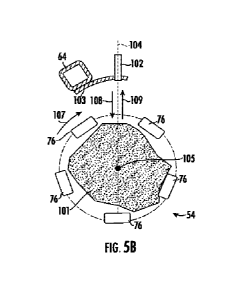
blades or bars of the basket assembly) and/or within the interior of the
basket
assembly. Such accumulation of field materials may prevent the basket assembly
from performing in a desired manner during the performance of a tillage
operation.
In such instances, it is often necessary for the operator to take certain
corrective
actions to remove the material accumulation, However, it is typically
difficult for the
operator to detect or determine a plugged condition of a basket assembly when
viewing the tools from the operator's cab.
[0004] Accordingly, an improved system and method
for monitoring plugging of
basket assemblies of an agricultural implement would be welcomed in the
technology.
1
CA 03146571 2022-2-1
WO 2021/030519
PCT/US2020/046051
SUMMARY OF THE INVENTION
[0005] Aspects and advantages of the technology
will be set forth in part in the
following description, or may be obvious from the description, or may be
learned
through practice of the technology.
[0006] In one aspect, the present subject matter is
directed to a system for
monitoring basket plugging for agricultural implements, The system includes a
basket
assembly configured to be supported by an agricultural implement and a range
sensor
positioned relative to the basket assembly such that the range sensor is
configured to
transmit detection signals towards an interior of the basket assembly and
receive
return signals based on reflection of the detection signals off at least one
surface. The
system also includes a controller communicatively coupled to the range sensor.
The
controller is configured to analyze data received from the range sensor as the
basket
assembly rotates relative to the range sensor to determine when the basket
assembly is
experiencing a plugged condition.
[0007] In another aspect, the present subject
matter is directed to an agricultural
implement that includes a frame, a basket assembly configured to be supported
by the
frame, and a range sensor supported relative to the basket assembly such that
the
range sensor has a line of detection directed towards an interior of the
basket
assembly. The range sensor configured to generate data associated a distance
between the range sensor and at least one surface aligned with the line of
detection as
the basket assembly is rotated relative to the range. The implement further
includes a
controller communicatively coupled to the range sensor. The controller is
configured
to analyze the data received from the range sensor to determine when the
basket
assembly is experiencing a plugged condition.
[0008] In a further aspect, the present subject
matter is directed to a method for
monitoring plugging of basket assemblies of agricultural implements. The
method
includes transmitting, with a range sensor, detection signals towards an
interior of a
basket assembly of an agricultural implement as the basket assembly is
rotating, and
receiving return signals based on reflection of the detection signals off at
least one
surface. In addition, the method includes analyzing, with a computing device,
data
associated at least in part with the return signals to determine when the
basket
assembly is experiencing a plugged condition.
2
CA 03146571 2022-2-1
WO 2021/030519
PCT/US2020/046051
[0009] These and other features, aspects and
advantages of the present technology
will become better understood with reference to the following description and
appended claims. The accompanying drawings, which are incorporated in and
constitute a part of this specification, illustrate embodiments of the
technology and,
together with the description, serve to explain the principles of the
technology.
BRIEF DESCRIPTION OF THE DRAWINGS
[0010] A full and enabling disclosure of the
present technology, including the best
mode thereof, directed to one of ordinary skill in the art, is set forth in
the
specification, which makes reference to the appended figures, in which:
[0011] FIG. 1 illustrates a perspective view of one
embodiment of an agricultural
implement coupled to a work vehicle in accordance with aspects of the present
subject
matter;
[0012] FIG. 2 illustrates another perspective view
of the agricultural implement
shown in FIG. 1 in accordance with aspects of the present subject matter;
[0013] FIG. 3 illustrates a partial perspective
view of basket assemblies
positioned at an aft end of the implement shown in FIGS. 1 and 2, particularly
illustrating one embodiment of a system for monitoring plugging of the basket
assemblies in accordance with aspects of the present subject matter;
[0014] FIGS. 4A and 413 illustrate a schematic,
simplified cross-sectional views of
one of the basket assemblies shown in FIG. 3 when such basket assembly is a
non-
plugged state, particularly illustrating a range sensor of the disclosed
system installed
relative to the basket assembly for detecting material accumulation on or
within the
basket assembly in accordance with aspects of the present subject matter;
[0015] FIGS. 5A and 58 illustrate similar
schematic, simplified cross-sectional
view of the basket assembly shown in FIGS. 4A and 48, but with the basket
assembly
now in a fully plugged state, particularly illustrating the range sensor being
used to
detect material accumulation within the basket assembly in accordance with
aspects
of the present subject matter;
[0016] FIG. 6 illustrates an exemplary plot showing
an example data trace or
profile associated with the sensor data collected by a range sensor of the
disclosed
3
CA 03146571 2022-2-1
WO 2021/030519
PCT/US2020/046051
system when a basket assembly is in a non-plugged state in accordance with
aspects
of the present subject matter;
[0017] FIG. 7 illustrates an exemplary plot showing
an example data trace or
profile associated with the sensor data collected by a range sensor of the
disclosed
system when a basket assembly is in a plugged state in accordance with aspects
of the
present subject matter;
[0018] FIG. 8 illustrates a schematic view of one
embodiment of a system for
monitoring plugging of a basket assembly of an agricultural implement in
accordance
with aspects of the present subject matter; and
[0019] FIG. 9 illustrates a flow diagram of one
embodiment of a method for
monitoring plugging of a basket assembly of an agricultural implement in
accordance
with aspects of the present subject matter.
[0020] Repeat use of reference characters in the
present specification and
drawings is intended to represent the same or analogous features or elements
of the
present technology.
DETAILED DESCRIPTION OF THE DRAWINGS
[0021] Reference now will be made in detail to
embodiments of the invention,
one or more examples of which are illustrated in the drawings. Each example is
provided by way of explanation of the invention, not limitation of the
invention. In
fact, it will be apparent to those skilled in the art that various
modifications and
variations can be made in the present invention without departing from the
scope or
spirit of the invention. For instance, features illustrated or described as
part of one
embodiment can be used with another embodiment to yield a still further
embodiment. Thus, it is intended that the present invention covers such
modifications
and variations as come within the scope of the appended claims and their
equivalents.
[0022] In general, the present subject matter is
directed to systems and methods
for monitoring plugging of one or more basket assemblies of an agricultural
implement. Specifically, in several embodiments, the disclosed system may
include
one or more range sensors supported relative to a given basket assembly such
that
each range sensor is configured to transmit detection signals towards an
interior of the
basket assembly. In addition, each range sensor may be configured to detect
return
4
CA 03146571 2022-2-1
WO 2021/030519
PCT/US2020/046051
signals corresponding to the detection signals as reflected off a detected
surface(s)..
By analyzing the return signals received by each range sensor (or the lack
thereof)
and/or any data associated with the signals, a controller or computing device
of the
system may infer or determine that the corresponding basket assembly is
currently
plugged or experiencing a plugged condition. For instance, in one embodiment,
the
controller may be configured to assess the data trace or profile of the sensor
data
received from each range sensor to identify the existence of material
accumulation on
and/or within the basket assembly. Once it is determined that the basket
assembly is
experiencing a plugged condition, an appropriate control action may then be
executed,
such as by notifying the operator of the plugged condition or by performing an
automated control action.
[0023] Referring now to the drawings, FIGS. 1 and 2
illustrate differing
perspective views of one embodiment of an agricultural implement 10 in
accordance
with aspects of the present subject matter. Specifically, FIG. 1 illustrates a
perspective view of the agricultural implement 10 coupled to a work vehicle
12.
Additionally, FIG. 2 illustrates a perspective view of the implement 10,
particularly
illustrating various components of the implement 10.
[0024] In general, the implement 10 may be
configured to be towed across a field
in a direction of travel (e.g., as indicated by arrow 14 in FIG. 1) by the
work vehicle
12. As shown, the implement 10 may be configured as a tillage implement, and
the
work vehicle 12 may be configured as an agricultural tractor. However, in
other
embodiments, the implement 10 may be configured as any other suitable type of
implement, such as a seed-planting implement, a fertilizer-dispensing
implement,
and/or the like. Similarly, the work vehicle 12 may be configured as any other
suitable type of vehicle, such as an agricultural harvester, a self-propelled
sprayer,
and/or the like.
100251 As shown in FIG. 1, the work vehicle 12 may
include a pair of front track
assemblies 16, a pair or rear track assemblies 18, and a frame or chassis 20
coupled to
and supported by the track assemblies 16, 18. An operator's cab 22 may be
supported
by a portion of the chassis 20 and may house various input devices for
permitting an
operator to control the operation of one or more components of the work
vehicle 12
and/or one or more components of the implement 10. Additionally, as is
generally
CA 03146571 2022-2-1
WO 2021/030519
PCT/US2020/046051
understood, the work vehicle 12 may include an engine 24 and a transmission 26
mounted on the chassis 20. The transmission 26 may be operably coupled to the
engine 24 and may provide variably adjusted gear ratios for transferring
engine power
to the track assemblies 16, 18 via a drive axle assembly (not shown) (or via
axles if
multiple drive axles are employed).
[0026] As shown in FIGS. 1 and 2, the implement 10
may include a frame 28_
More specifically, as shown in FIG. 2, the frame 28 may extend longitudinally
between a forward end 30 and an aft end 32. The frame 28 may also extend
laterally
between a first side 34 and a second side 36. In this respect, the frame 28
generally
includes a plurality of structural frame members 38, such as beams, bars,
and/or the
like, configured to support or couple to a plurality of components.
Furthermore, a
hitch assembly 40 may be connected to the frame 28 and configured to couple
the
implement 10 to the work vehicle 12. Additionally, a plurality of wheels 42
(one is
shown) may be coupled to the frame 28 to facilitate towing the implement 10 in
the
direction of travel 14.
[0027] In several embodiments, the frame 28 may be
configured to support
various ground engaging tools, For instance, the frame 28 may support one or
more
gangs or sets 44 of disc blades 46. Each disc blade 46 may be configured to
penetrate
into or otherwise engage the soil as the implement 10 is being pulled through
the
field. In this regard, the various disc gangs 44 may be oriented at an angle
relative to
the direction of travel 14 to promote more effective tilling of the soil. In
the
embodiment shown in FIGS. 1 and 2, the implement 10 includes four disc gangs
44
supported on the frame 28 adjacent to its forward end 30. However, it should
be
appreciated that, in alternative embodiments, the implement 10 may include any
other
suitable number of disc gangs 44, such as more or fewer than four disc gangs
44.
Furthermore, in one embodiment, the disc gangs 44 may be mounted to the frame
28
at any other suitable location, such as adjacent to its aft end 32.
[0028] Additionally, as shown, in one embodiment,
the implement frame 28 may
be configured to support other ground engaging tools. For instance, in the
illustrated
embodiment, the frame 28 is configured to support a plurality of shanks 50
configured
to rip or otherwise till the soil as the implement 10 is towed across the
field.
Furthermore, in the illustrated embodiment, the frame 28 is also configured to
support
6
CA 03146571 2022-2-1
WO 2021/030519
PCT/US2020/046051
one or more finishing tools, such as a plurality of leveling blades 52 and/or
rolling (or
crumbler) basket assemblies 54. However, in other embodiments, any other
suitable
ground-engaging tools may be coupled to and supported by the implement frame
28,
such as a plurality of closing discs.
[0029] Referring now to FIG. 3, a partial,
perspective view of the all end of the
implement 10 shown in FIGS. 1 and 2 is illustrated in accordance with aspects
of the
present subject matter, particularly illustrating a portion of the finishing
tools 52, 54
of the implement 10. As shown, the various finishing tools 52, 54 may be
coupled to
or supported by the implement frame 28, such as by coupling each tool to a
toolbar or
laterally extending frame member 38 of the frame 28. For instance, as shown in
FIG.
3, a blade support arm 60 may be coupled between a given frame member 38 and
each leveling blade 52 or set of leveling blades 52 to support the blades 52
relative to
the frame 28. Similarly, one or more basket support arms 62 may be coupled
between
a given frame member 38 and an associated mounting yoke or basket hanger 64
for
supporting each basket assembly 54 relative to the frame 28. Additionally, as
shown
in FIG. 3, in one embodiment, a basket actuator 66 (e.g., a hydraulic or
pneumatic
cylinder) may be coupled to each basket support arm 62 to allow the down force
or
down pressure applied to each basket assembly 54 to be adjusted. The basket
actuators 66 may also allow the basket assemblies 54 to be raised off the
ground, such
as when the implement 10 is making a headland turn and/or when the implement
10 is
being operated within its transport mode.
[0030] In several embodiments, each basket assembly
54 includes a plurality of
support plates 70, 72, 74 configured to support a plurality of blades or bars
76 spaced
circumferentially about the outer perimeter of the basket. For instance, as
shown in
FIG. 3, each basket assembly 54 includes first and second end plates 70, 72
positioned
at the opposed lateral ends of the basket assembly 54 and a plurality of inner
support
plates 74 spaced apart laterally from one another between the end plates 70,
72.
Lateral basket sections 78 are generally defined between each pair of adjacent
support
plates 70, 72, 74, with each basket section 78 being generally characterized
by a
hollow or substantially hollow interior area surrounded by the lateral
portions of the
bars 76 extending between the respective pair of adjacent support plates 70,
72, 74.
As is generally understood, the end plates 70, 72 may be rotatably coupled to
the
7
CA 03146571 2022-2-1
WO 2021/030519
PCT/US2020/046051
corresponding basket hanger 64 (which, in turn, is coupled to the associated
bracket
support arm(s) 62) via bearings to allow the basket assembly 54 to rotate
relative to
the hanger/arm 64, 62 as implement 10 is being moved across the field.
Additionally,
in the illustrated embodiment, the bars 76 of each basket assembly 54 are
configured
as formed bars. However, in other embodiments, the bars 76 may have any other
suitable configuration, such as flat bars, round bars, antiVor the like.
[0031] Moreover, in accordance with aspects of the
present subject matter, FIG. 3
also illustrates components of one embodiment of a system 100 for monitoring
plugging of one or more basket assemblies of an agricultural implement
Specifically,
in the illustrated embodiment, the system 100 is shown as being configured for
use in
identifying and monitoring a plugged condition(s) of the depicted basket
assemblies
54. However, in other embodiments, the system 100 may be utilized to monitor
plugging of basket assemblies having any other suitable configuration.
[0032] As shown in FIG. 3, the system 100 includes
one or more range sensors
102 installed on the implement 10 at a location relative to each basket
assembly 54
such that each range sensor(s) 102 is configured to provide data indicative of
a
plugged condition of the basket assembly 54, Specifically, in several
embodiments,
each range sensor 102 may be installed relative to an adjacent basket assembly
54
such that the range sensor 102 is configured to transmit detection signals
towards the
interior of the basket assembly 54 along a line of sight or line of detection
104 (FIGS_
4A, 48, 5A, and 58) of the range sensor 102 and subsequently receive return
signals
corresponding to the detection signals as reflected off a given surface
aligned with the
line of detection 104 at such point in time, such as an outer surface of the
bars 76 or
the surface(s) of field materials that have accumulated on and/or within the
basket
assembly. By analyzing the return signals via an associated controller 106
(FIG. 8)
communicatively coupled to each range sensor 102, the controller 106 may be
configured to identify the presence of material accumulation on or within the
basket
assembly.
[0033] For instance, the return signals received by
each range sensor 102 may be
indicative of the distance defined between the sensor 102 and the
corresponding
reflection surface. In this regard, as the basket assembly 54 is rotated
relative to each
range sensor 102, the deflection signals transmitted from such range sensor
102 at any
8
CA 03146571 2022-2-1
WO 2021/030519
PCT/US2020/046051
given point in time will either be directed towards one of the bars 76
surrounding the
interior of the basket assembly 54 or the open space defined between adjacent
bars 76,
depending on the rotational orientation of the basket assembly 54 relative to
the range
sensor 102 at such point in time. As a result, when the adjacent basket
assembly 54
is in a normal, un-plugged state (e.g., the interior of the basket assembly 54
is not
occupied by field materials), the profile of the distance-related data
associated with
the return signals received by each range sensor 102 will generally correspond
to a
periodic or wave-like profile characterized by the deflection signals
alternating
between being reflected off of the spaced apart bars 76 and being transmitted
between
adjacent bars 76 through the open interior of the basket assembly 54. However,
as
field materials accumulate within the interior of the basket assembly 54, the
detection
signals directed from each range sensor 102 towards the open areas defined
between
adjacent bars 76 will bounce or reflect off the accumulated materials, thereby
altering
the data trace or profile of the distance-related data associated with the
return signals
received by the range sensor 102. Similarly, as field materials accumulate
around the
outer perimeter of the basket assembly 54 (e.g. on the bars 76), the detection
signals
directed from each range sensor 102 will bounce or reflect off the accumulated
materials as opposed to reflecting off the bars 76 or being transmitted into
the interior
of the basket assembly 54, thereby altering the data profile of the distance-
related data
associated with the return signals received by the range sensor 102.
Accordingly, by
recognizing variations in the data profile (particularly variations indicative
of a
reduction in the distance detected between the sensor 102 and an associated
reflection
surface), the controller 106 may infer or estimate that the basket assembly 54
is
experiencing a plugged condition. Once a plugged condition is detected, an
appropriate control action may then be executed, such as by notifying the
operator of
the plugged condition or by performing an automated control action.
100341 In general, the range sensors 102 may
correspond to any suitable distance
sensors, proximity sensors, and/or the like that are configured to collect
data
indicative of a distance or range defined between such sensors 102 and a given
object/surface. For instance, in one embodiment, each range sensor 102may
correspond to an optical distance sensor, such as a laser-based distance
sensor. In
another embodiment, each range sensor 102 may correspond to ultrasound-based
9
CA 03146571 2022-2-1
WO 2021/030519
PCT/US2020/046051
distance sensor. Laser-based distance sensors and ultrasound-based distance
sensors
suitable for use within the disclosed system 100 are commercially available
from
various sources, including, for example, from Banner Engineering Corp. of
Minneapolis, MN. In other embodiments, each range sensor 102 may correspond to
any other suitable distance or proximity sensor or sensing device, such as a
radar-
based distance sensor, an inductance-based distance sensor, a sonar-based
distance
sensor, magnetic-based distance sensor, a LIDAR sensor, and/or the like.
[0035] As shown in FIG. 3, the range sensors 102
are mounted to the basket
hanger 64 supporting each basket assembly 54 relative to the implement frame
28
(e.g., via the associated basket support arm 62) in a manner such that each
range
sensor 102 has a downwardly oriented line of sight or line of detection 104
(FIGS.
4A, 48, 5A, and 5B) directed towards the interior of the adjacent basket
assembly 54.
Specifically, in the illustrated embodiment, the range sensors 102 are spaced
apart
laterally across each basket hanger 64 such that at least one range sensor 102
has a
downwardly oriented line of detection directed towards the interior of each
lateral
basket section 78 of the adjacent basket assembly 54. As a result, the range
sensors
102 may allow the plugging state of each respective basket section 78 to be
individually monitored. However, in other embodiments, the range sensors 102
may
be mounted at any other suitable location relative to the basket assembly 54
that
allows each range sensor 102 to have a line of detection directed towards the
interior
of an associated basket assembly 54. Additionally, although the illustrated
embodiment shows a specific number of range sensors 102 installed relative to
each
basket assembly 54 (e.g., one per each lateral basket section 78), the system
100 may
generally include any suitable number of range sensors 102, including a single
range
sensor 102 for each basket assembly 54.
[0036] Referring now to FIGS. 4A and 48 and FIGS.
5A and 58, schematic,
simplified cross-sectional views of one of the basket assemblies 54 shown in
FIG. 3
are illustrated in accordance with aspects of the present subject matter.
Specifically,
FIGS. 4A and 4B illustrate the basket assembly 54 in a non-plugged state such
that
the basket interior and exterior is completely devoid of material
accumulation.
Additionally, FIGS. 5A and 5B illustrates the basket assembly 54 when it is
experiencing an internal plugged condition such that the basket interior
includes field
CA 03146571 2022-2-1
WO 2021/030519
PCT/US2020/046051
materials (indicated by mass 101) accumulated therein. For purposes of
illustration,
the basket assembly 54 of FIGS. 5A and 5B is shown in an almost fully plugged
state.
However, those of ordinary skill in the art will appreciate that basket
assemblies 54
can experience varying degrees of plugged conditions, such as ranging from a
partially plugged condition to a fully plugged condition.
[0037] As shown in FIGS. 4A, 4B, 5A, and 5B, the
range sensor 102 is coupled to
the adjacent basket hanger 64 (e.g., via a mounting bracket 103) such that the
sensor
102 has a line of detection 104 oriented towards the interior of the basket
assembly
54. Specifically, in the illustrated embodiment, the line of detection 104 of
the sensor
102 is directed towards a center 105 of the basket assembly 54, which may also
coilespond to the location of the rotational axis of the basket assembly 54.
However,
in other embodiments, the line of detection 104 of the range sensor 102 may be
directed towards any other location(s) within the interior of the basket
assembly 54,
such as any off-center location.
[0038] As particularly shown in FIGS. 4A and 4B, as
the non-plugged basket
assembly 54 rotates in a given rotational direction (e.g., as indicated by
arrow 107)
across the ground (and relative to the sensor 102) during the performance of
an
agricultural operation (e.g., a tillage operation), the line of detection 104
of the range
sensors 102 alternates from being aligned with one of the bars 76 of the
basket
assembly 54 to being aligned with the open area or gap defined adjacent bars
76. For
example, in the snapshot shown in FIG. 4A, the line of detection 104 is
aligned with
one of the bars 76 of the basket assembly 54. As a result, the detection
signals
(indicated by arrow 108) transmitted from the range sensor 102 may reflect off
the
outer surface of the aligned bar 76 and be directed back to the range sensor
102 as
retturi signals (indicated by arrow 109). Such return signals 109 may then be
analyzed, for example, to identify the distance between the sensor 102 and the
aligned
bar 76 (or, as will be described below, to identify distance between the
aligned bar 76
and the basket center 105 via a linear transformation). In contrast, in the
subsequent
snapshot shown in FIG. 4B in which the basket assembly 54 has rotated slightly
in the
rotational direction 107 from the position shown in FIG. 4A, the line of
detection 104
is aligned with the open space defined between adjacent bars 76 of the basket
assembly 54. As a result, the detection signals 108 transmitted from the range
sensor
11
CA 03146571 2022-2-1
WO 2021/030519
PCT/US2020/046051
102 may pass between the adjacent bars 76 and through the open interior of the
basket
assembly 54 to the basket center 105 or beyond. As the basket assembly 54 is
further
rotated in the rotational direction 107 from the position shown in FIG. 48,
the next
adjacent bar 76 will pass through the line of detection 104 of the range
sensor 102,
thereby allowing the sensor 102 to detect the bar. Such alternating pattern
will be
repeated as the basket assembly 54 rotates relative to the range sensor 102
during
operation of the agricultural implement.
[0039] It should be appreciated that, in the
illustrated embodiment, the detection
range of the range sensor 102 has generally been selected to generally
correspond to
the distance defined between the sensor 102 and the basket center 105. As a
result,
when the basket assembly 54 is in a non-plugged state, the range sensor 102
will not
receive return signals when the line of detection 104 for the range sensor 102
is
aligned with the open space between adjacent bars 76 (e.g., as shown in FIG.
4B),
thereby indicating that the detection signals 108 reached the center 105 of
the basket
assembly 54. In other embodiments, the range sensor 102 may have any other
suitable detection range. For instance, in another embodiment, the detection
range
may be selected to correspond to the distance defined between the sensor 102
and the
ground (or the opposed side of the basket assembly 54 contacting the ground).
In
such an embodiment, when the line of detection 104 for the range sensor 102 is
aligned with the open space between adjacent bars 76 (e.g., as shown in FIG.
413), the
detection signals 108 may be transmitted through the interior of the basket
assembly
54 and reflect off the opposed side of the basket assembly 54 (e.g., a bar
positioned at
such opposed side) or the ground and be returned back to the sensor 102 as
suitable
return signals.
[0040] When the basket assembly 54 is experiencing
a plugged condition, the
same alternating pattern will be repeated as the basket assembly 54 rotates
relative to
the range sensor 102 during operation of the agricultural implement, with the
line of
detection 104 alternating between being aligned with one of the bars 76 of the
basket
assembly 54 and being aligned with the open space defined between adjacent
bars 76.
For instance, the line of detection 104 of the range sensor 102 is aligned
with one of
the bars 76 of the basket assembly 54 in the snapshot shown in FIG. 5A, while
the
line of detection 104 is aligned with the open space defined between adjacent
bars 76
12
CA 03146571 2022-2-1
WO 2021/030519
PCT/US2020/046051
in the snapshot shown in FIG. 5B. However, unlike the non-plugged state
described
above with reference to FIGS. 4A and 4B, the detection signals 108 transmitted
from
the range sensor 102 will not pass through the interior of the basket assembly
54 to its
center 105 when the line of detection 104 is aligned with the open space
defined
between adjacent bars 76 due to the presence of material accumulation within
the
interior of the basket assembly 54_ Specifically, as shown in FIG. 5B, the
detection
signals 108 transmitted from the range sensor 102 reflect off the outer
surface(s) of
the accumulated material 101 and are directed back to the range sensor 102 as
return
signals 109. Such return signals 109 may then be analyzed, for example, to
identify
the distance between the sensor 102 and the accumulated materials 101 (or, as
will be
described below, to identify distance between the accumulated materials 101
and the
basket center 105 via a linear transformation). When such material
accumulation is
detected, it may be inferred or determined that the basket assembly 54 is
experiencing
a plugged condition.
[0041] It should be appreciated that, although not
shown, the basket assembly 54
may also experience an external plugging condition in which field materials
accumulate along the outer perimeter of the basket assembly 54, such as on or
between the bars 76. In such instance, the range sensor 102 may detect the
material
accumulation in a manner similar to that described. For instance, material
accumulation on the bars 76 will result in a reduction in the distance
detected between
the sensor and the expected location of the bars 76. Similarly, material
accumulation
directly between the bars 76 will prevent the detection signals 108 from being
transmitted through the interior of the basket assembly 54, which may be
detected by
the range sensor 102 via the associated return signals 109 reflecting off the
accumulated materials.
[0042] Referring now to FIGS. 6 and 7, exemplary
charts are provided that
illustrate example data traces or profiles associated with the sensor data
provided by
the range sensor 102 in the non-plugged/plugged scenarios described above with
reference to FIGS. 4A and 4B and FIGS. 5A and 5B. Specifically, FIG. 6
illustrates
an exemplary data profile associated with the return signals 109 received by
the range
sensor 102 (or lack thereof) while the basket assembly 54 is in the non-
plugged state
shown in FIGS. 4A and 413. Similarly, FIG. 7 illustrates an exemplary data
profile
13
CA 03146571 2022-2-1
WO 2021/030519
PCT/US2020/046051
associated with the return signals 109 received by the range sensor 102 while
the
basket assembly 54 is in the plugged state shown in FIGS. 5A and 5B. It should
be
appreciated that the data collected from the range sensor 102 is generally
indicative of
the distance defined between the sensor 102 and the detected surface(s).
However,
for purposes of illustration, the sensor data has been plotted as a function
of the
distance of the detected surface from the center 105 of the basket assembly
54. Such
center-referenced data may be obtained via a linear transformation. In doing
so, any
sensor measurements that extend beyond the center 105 of the basket assembly
54
(e.g., when the detection range of the range sensor 102 extends past the
basket center
105) may be saturated prior to performing the linear transformation.
[0043] As particularly shown in FIG. 6, when the
basket assembly 54 is a non-
plugged state, the sensor data may exhibit a periodic or alternating profile
as the line
of detection 104 of the range sensor 102 alternates between being aligned with
one of
the bars 76 and being aligned with the open spaces defined between adjacent
bars 76.
Specifically, the data trace is characterized by a repeating pattern of peaks
180 and
valleys 182, with each peak 180 corresponding to the time period across which
one of
the bars 76 of the basket assembly 54 is being rotated across the line of
detection 104
of the sensor 102 and each valley 182 corresponding to the time period across
which
the detection signals 108 from the range sensor 102 are being transmitted
between
adjacent bars 76 through the interior of the basket assembly 54 to at least
the basket
center 105. As shown in FIG. 6, each peak 180 corresponds to a distance from
the
basket center 108 equal to an outer radius R (see FIG. 4A) of the basket
assembly 54
(i.e., the distance from the basket center 105 to the outer surfaces of the
bars 76),
while each valley 182 corresponds to a distance from the basket center 105
equal to
zero. As such, the non-plugged data trace or profile for the basket assembly
54
generally exhibits a periodic profile with a very high variation or
differential in the
detected distances between the peaks 180 and valleys 182.
[0044] In contrast, as shown in FIG. 7, the data
trace or profile associated with
the sensor data received from the range sensor 102 differs significantly when
the
basket assembly 54 is experiencing a plugged condition. Specifically, due to
the
detection of material accumulation, the variability in the detected distances
is reduced
significantly. For instance, in the illustrated example, the data trace is
characterized a
14
CA 03146571 2022-2-1
WO 2021/030519
PCT/US2020/046051
similar repeating pattern of peaks 180 and valleys 184 as that described above
with
reference to FIG. 6, with each peak 180 coliesponding to the time period
across which
one of the bars 76 of the basket assembly 54 is being rotated across the line
of
detection 104 of the sensor 102. However, in the exemplary plot of FIG 7, each
valley 184 corresponds to the time period across which the detection signals
from the
range sensor 102 are being transmitted between adjacent bars 76 and being
reflected
off the accumulated field materials. As shown in FIG. 7, given the plugged
state of
the basket assembly 54, the variation between the detected distance from the
basket
center 105 to the outer surfaces of the bars 76 and the detected distances
from the
basket center 105 to the outer surface(s) of the accumulated materials is
significantly
smaller than the distance variations described above with reference to FIG. 6.
Such a
reduced differential between the maximum and minimum distance values detected
during rotation of the basket assembly 54 provides a significant indicator of
material
accumulation relative to the basket assembly.
[0045] Referring now to FIG. 8, a schematic view of
one embodiment of a system
100 for monitoring plugging of one or more basket assemblies of an
agricultural
implement is illustrated in accordance with aspects of the present subject
matter. In
general, the system 100 will be described with reference to the implement 10
shown
in FIGS. 1 and 2 and the basket assembly 54 and associated system components
shown in FIG. 3. However, in other embodiments, the disclosed system 100 may
be
utilized to identifying tool plugging in association with any other suitable
agricultural
implement having any other suitable implement configuration, any other
suitable
basket assembly having any other suitable basket configuration, and/or using
system
components having any other suitable component configuration(s).
[0046] As indicated above, in several embodiments,
the system 100 may include
one or more range sensors 102 installed relative to a basket assembly 54 such
that
each range sensor(s) 102 is configured to provide data indicative of a plugged
condition of the basket assembly 54. Additionally, as indicated above, the
system 100
may also include a controller 106 communicatively coupled to the range
sensor(s)
102. As will be described in greater detail below, the controller 106 may be
configured to analyze the return signals received by the range sensor(s) 102
(or the
lack thereof) and/or related data associated with such signals to infer or
estimate the
CA 03146571 2022-2-1
WO 2021/030519
PCT/US2020/046051
existence of material accumulation on and/or within the associated basket
assembly
54. Additionally, the controller 106 may also be configured to execute one or
more
control actions in response to the determination that the basket assembly 54
is likely
plugged or in the process of becoming plugged. For instance, in one
embodiment, the
controller 106 may notify the operator that the basket assembly 54 is plugged
or is
likely to become plugged in the near future. In addition to notifying the
operator (or
as an alternative thereto), the controller 106 may be configured to execute
one or
more automated control actions adapted to de-plug the basket assembly 54 or
otherwise reduce the amount of material accumulation on and/or within the
basket
assembly 54, such as by automatically adjusting the speed of the implement 10
and/or
the down force applied to the basket assembly 54 and/or by automatically
raising and
lowering the basket assembly 54 relative to the ground.
[0047] In general, the controller 106 may
correspond to any suitable processor-
based device(s), such as a computing device or any combination of computing
devices. Thus, as shown in FIG. 8, the controller 106 may generally include
one or
more processor(s) 110 and associated memory devices 112 configured to perform
a
variety of computer-implemented functions (e.g., performing the methods,
steps,
algorithms, calculations and the like disclosed herein). As used herein, the
term
"processor" refers not only to integrated circuits referred to in the art as
being
included in a computer, but also refers to a controller, a microcontroller, a
microcomputer, a programmable logic controller (PLC), an application specific
integrated circuit, and other programmable circuits. Additionally, the memory
112
may generally comprise memory element(s) including, but not limited to,
computer
readable medium (e.g., random access memory (RAM)), computer readable non-
volatile medium (e.g., a flash memory), a floppy disk, a compact disc-read
only
memory (CD-ROM), a magneto-optical disk (MOD), a digital versatile disc (DVD)
and/or other suitable memory elements. Such memory 112 may generally be
configured to store information accessible to the processor(s) 110, including
data 114
that can be retrieved, manipulated, created and/or stored by the processor(s)
110 and
instructions 116 that can be executed by the processor(s) 110.
[0048] In several embodiments, the data 114 may be
stored in one or more
databases. For example, the memory 112 may include a signal database 118 for
16
CA 03146571 2022-2-1
WO 2021/030519
PCT/US2020/046051
storing the return signals received by the range sensor(s) 102 and/or data
associated
with the received signals. For instance, in addition to the return signals
received by
the range sensor(s) 102, data may be stored within the signal database 118
associated
with the distance defined between the sensor(s) 102 and the detected surface.
Moreover, when desired, the signal database 118 may also be used to store any
modified or transformed sensor data, such as when it is desired to transform
the
distance data from being referenced relative to the sensor location to being
referenced
relative to the center 105 of the basket assembly 54 or any other suitable
reference
location.
[0049] Additionally, as shown in FIG. 8, the memory
112 may include a field
parameter database 120 for storing information related to one or more
parameters of
the field being processed during the performance of the associated
agricultural
operation (e.g., a tillage operation). In one embodiment, moisture data
associated
with the moisture content or level of the soil within the field may be stored
within the
field parameter database 120. Depending on the sensor technology being
utilized, the
wetness or moisture content of the soil may impact the ability of the range
sensor(s)
102 of detecting plugged conditions. For instance, material accumulation
including
significantly high soil moisture may alter the manner in which the detection
signals
reflect off the accumulated field materials, which may negatively impact the
resulting
return signals received by the range sensor(s) 102. Accordingly, by knowing
the soil
moisture within the field, the controller 106 may be configured to more
accurately
assess the return signals received by the range sensor(s) 102.
[0050] It should be appreciated that the moisture
data may be correspond to pre-
existing or predetermined moisture data stored within the field parameter
database
120 or the moisture data may correspond to sensor data that is being actively
collected
or generated during the performance of the associated agricultural operation.
For
instance, in one embodiment, the controller 106 may be provided with soil
moisture
data (e.g., in the form of a soil moisture map) that was collected during a
previous
agricultural operation or that was generated based on previously known data
associated with the field conditions. Alternatively, a soil moisture sensor
may be
provided in operative association with the implement 10 or the towing vehicle
12 to
17
CA 03146571 2022-2-1
WO 2021/030519
PCT/US2020/046051
allow the soil moisture to be actively monitored during the performance of the
associated agricultural operation.
[0051] Referring still to FIG. 8, in several
embodiments, the instructions 116
stored within the memory 112 of the controller 106 may be executed by the
processor(s) 110 to implement an analysis module 122. In general, the analysis
module 122 may he configured to analyze the return signals received by each
range
sensor(s) 102 (or a lack thereof) and/or the related data (e.g., distance
data) to
estimate or infer when the associated basket assembly 54 is experiencing a
plugged
condition. Specifically, in several embodiments, the analysis module 122 may
be
configured to determine when the basket assembly 54 is experiencing a plugged
condition by analyzing the data trace or profile of the data associated with
the return
signals received by each range sensor(s) 102.
[0052] In one embodiment, the analysis module 122
may be configured to
compare or analyze the current data trace or profile associated with the
sensor data in
view of a predetermined, non-plugged data trace or profile, such as the non-
plugged
data profile described above with reference to FIG. 6. In such an embodiment,
the
analysis module 122 may, for example, compare the variability or differential
in the
distance data detected within the current data profile to the variability or
differential
of the distance data associated with the non-plugged data profile. If a
significant
variation exists between the current data profile and the non-plugged data
profile
(e.g., a variation indicating that the distance variability or differential in
the current
data profile is significantly reduced relative to the distance variability or
differential in
the non-plugged data profile), the analysis module 122 may estimate or infer
that the
associated basket assembly is experiencing a plugged condition.
[0053] In another embodiment, the analysis module
122 may be configured to
analyze the distance data associated with the return signals received by each
range
sensor(s) 102 (or a lack thereof) by calculating a detection range metric for
the
associated range sensor 102. In general, the detection range metric may be
indicative
of a percentage of the detection signals transmitted from a given range sensor
102 that
reach a given location within the interior of the basket assembly 54 (or that
reach to
within a given range of locations defined relative to such location within the
interior
of the basket assembly 54). The analysis module 122 may then be configured to
18
CA 03146571 2022-2-1
WO 2021/030519
PCT/US2020/046051
determine when the basket assembly 54 is experiencing a plugged condition
based at
least in part on the detection range metric. For instance, the analysis module
122 may
be configured to compare the calculated detection range metric to a
predetermined
threshold. In such an embodiment, it may be inferred or estimated that the
basket
assembly 54 is experiencing a plugged condition when the detection range
metric
crosses such predetermined threshold (e.g., by falling below the threshold).
[0054] In a particular embodiment of the present
subject matter, the detection
range metric may be indicative of a percentage of the detection signals
transmitted
from a given range sensor 102 that reach the center 105 of the basket assembly
54 (or
at least within a given radius of the center 105 of the basket assembly 54).
For
instance, the analysis module 122 may be configured to calculate a proximity
center
crossing (PCC) metric indicative of the percentage of detection signals that
reach
within a given radius defined from the basket center 105 (e.g., a radius of
less than 10
centimeters (cm), such as a radius of less than 7.5 cm or less than 5 cm or
less than
2.5 cm) across a given time period (e.g., a time period of 1 second, 2
seconds, 3
seconds, and/or the like). In one embodiment, the PCC metric may be calculated
using the following formula (Equation 1):
(Po-P2
PCC ¨
*100 (1)
wherein, PCC corresponds to the percentage of the detection signals
transmitted from the range sensor 102 that reach within a given radius defined
from
the basket center 105 over a given sampling period, 71 corresponds to the
number of
samples collected by the range sensor 105 over the sampling period given the
sensor's
sampling rate, and P corresponds to an intermediate variable that is assigned
a value
of one (1) if the detection signal transmitted at such instance reaches to
within the
predetermined radius defined from the basket center 105 and is assigned a
value of
zero (0) if the detection signal transmitted at such instance does not reach a
location
within such predetermined radius (e.g., due to the signal being reflected off
the basket
bars 76 or accumulated material).
[0055] By utilizing the above-described metric, a
higher PCC percentage value
indicates that a significant amount of the detection signals transmitted by
the range
sensor 102 are able to reach down to a location at or adjacent to the basket
center 105,
19
CA 03146571 2022-2-1
WO 2021/030519
PCT/US2020/046051
thereby indicating that the basket assembly 54 is likely in an non-plugged
state. In
contrast, a lower PCC percentage value indicates that a smaller amount of the
detection signals transmitted by the range sensor 102 were able to reach down
to a
location at or adjacent to the basket center, thereby indicating that the
basket assembly
54 is likely experiencing a plugged condition. In one embodiment, to assess
the
current PCC percentage value calculated for a given range sensor 102, such
value may
be compared to a predetermined PCC threshold. For instance, the PCC threshold
may
be set to a given percentage value, such as a percentage ranging from about
70% to
about 10%, or from about 60% to about 20%, or from about 50% to about 30%, or
from about 45% to about 35%, and/or any other subranges therebetween. In such
an
embodiment, when the current PCC percentage value calculated for a given range
sensor 203 crosses or drops below the predetermined PPC threshold, it may be
inferred or estimated that the basket assembly 54 is experiencing a plugged
condition
at the location along the basket assembly 54 at which the range sensor 102 is
directed.
For instance, if the PCC threshold is set as 40%, any PCC percentage value
below
such threshold indicates that less than 40% of the detection signals
transmitted from
the associated range sensor 102 are currently reaching a location within the
predetermined radius defined from the basket center 105.
[0056] As indicated above, in one embodiment, the
system 100 may include a
plurality of range sensors 102, with at least one range sensor 102 being
aligned with
each lateral basket section 78 of a given basket assembly 54 to allow material
accumulation to be detected on a section-level basis for the basket assembly
54. In
such an embodiment, the analysis module 122 may be configured to individually
analyze the return signals and/or associated signal data received by each
range sensor
102 to determine whether a plugged condition exists within the localized area
being
detected by each range sensor 102.
[0057] Referring still to FIG. 8, the instructions
116 stored within the memory
112 of the controller 106 may also be executed by the processor(s) 110 to
implement
a control module 124. In general, the control module 124 may be configured to
initiate a control action when it is determined that a basket assembly of an
agricultural
implement is experiencing a plugged condition. As indicated above, in one
embodiment, the control module 124 may be configured to provide a notification
to
CA 03146571 2022-2-1
WO 2021/030519
PCT/US2020/046051
the operator of the vehicle/implement 12/10 indicating that material
accumulation is
present on or within one or more of the basket assemblies 54 of the implement
10.
For instance, in one embodiment, the control module 124 may cause a visual or
audible notification or indicator to be presented to the operator via an
associated user
interface 126 provided within the cab 22 of the vehicle 10.
[0058] In other embodiments, the control module 124
may be configured to
execute an automated control action designed to adjust the operation of the
implement
10. For instance, in one embodiment, the controller 106 may be configured to
increase or decrease the operational or ground speed of the implement 10 in an
attempt to reduce the amount of material accumulation and/or to limit further
material
accumulation. For instance, as shown in FIG. 8, the controller 106 may be
communicatively coupled to both the engine 24 and the transmission 26 of the
work
vehicle 12. In such an embodiment, the controller 106 may be configured to
adjust
the operation of the engine 24 and/or the transmission 26 in a manner that
increases or
decreases the ground speed of the work vehicle 12 and, thus, the ground speed
of the
implement 10, such as by transmitting suitable control signals for controlling
an
engine or speed governor (not shown) associated with the engine 24 and/or
transmitting suitable control signals for controlling the
engagement/disengagement of
one or more clutches (not shown) provided in operative association with the
transmission 26. It should be appreciated that controller 106 may also be
configured
to decrease the wound speed in a manner that brings vehicle/implement 12/10 to
a
complete stop.
[0059] In addition to the adjusting the ground
speed of the vehicle/implement 12,
(or as an alternative thereto), the controller 106 may also be configured to
adjust an
operating parameter associated with the ground-engaging tools of the implement
10.
For instance, as shown in FIG. 8, the controller 106 may be communicatively
coupled
to one or more valves 128 configured to regulate the supply of fluid (e.g.,
hydraulic
fluid or air) to one or more corresponding actuators of the implement 10, such
as the
basket actuators 66. hi such an embodiment, by regulating the supply of fluid
to the
actuator(s) 66, the controller 106 may automatically adjust the down force or
down
pressure applied to the associated basket assembly 54. Additionally, the
controller
21
CA 03146571 2022-2-1
WO 2021/030519
PCT/US2020/046051
106 may control the operation of the basket actuator 66 to raise and lower the
associated basket assembly 54 relative to the ground.
[0060] Moreover, as shown in FIG. 8, the controller
106 may also include a
communications interface 130 to provide a means for the controller 106 to
communicate with any of the various other system components described herein.
For
instance, one or more communicative links or interfaces 132 (e.g., one or more
data
buses) may be provided between the communications interface 130 and the range
sensor(s) 102 to allow the signals received by the range sensor(s) 102 (and/or
related
signal data) to be transmitted to the controller 106. Similarly, one or more
communicative links or interfaces 134 (e.g., one or more data buses) may be
provided
between the communications interface 134 and the engine 24, the transmission
26, the
user interface 126, the control valves 128, and/or the like to allow the
controller 106
to control the operation of and/or otherwise communicate with such system
components.
[0061] Referring now to FIG. 9, a flow diagram of
one embodiment of a method
200 for monitoring plugging of basket assemblies of an agricultural implement
is
illustrated in accordance with aspects of the present subject matter. In
general, the
method 200 will be described herein with reference to the agricultural
implement 10,
the basket assembly 54, and the system 100 described above with reference to
FIGS.
1-3 and 8. However, it should be appreciated by those of ordinary skill in the
art that
the disclosed method 200 may generally be implemented with any agricultural
implement having any suitable implement configuration, any basket assembly
having
any suitable basket configuration, and/or any system having any suitable
system
configuration. In addition, although FIG. 9 depicts steps performed in a
particular
order for purposes of illustration and discussion, the methods discussed
herein are not
limited to any particular order or arrangement. One skilled in the art, using
the
disclosures provided herein, will appreciate that various steps of the methods
disclosed herein can be omitted, rearranged, combined, and/or adapted in
various
ways without deviating from the scope of the present disclosure.
[0062] As shown in FIG. 9, at (202), the method 200
may include transmitting,
with a range sensor, detection signals towards an interior of a basket
assembly of an
agricultural implement as the basket assembly is rotating. For example, as
indicated
22
CA 03146571 2022-2-1
WO 2021/030519
PCT/US2020/046051
above, one or more range sensors 102 may be installed relative to a basket
assembly
54 of an agricultural implement 10, with each range sensor 102 being
configured to
transmit detection signals along a line of detection 104 towards the interior
of the
basket assembly 54.
[0063] Additionally, at (204), the method 200 may
include receiving return
signals based on reflection of the detection signals off at least one surface.
Specifically, as indicated above, the detection signals transmitted from each
range
sensor 102 may reflect off a given surface (e.g., the outer surface of the
bars 76 of the
associated basket assembly 54 and/or the surface(s) of the accumulated field
materials) and be subsequently detected as return signals by the range sensor.
[0064] Moreover, as shown in FIG. 9, at (206), the
method 200 may include
analyzing data associated at least in part with the return signals to
determine when the
basket assembly is experiencing a plugged condition. For instance, as
indicated
above, the controller 106 may be configured to infer or estimate that a basket
assembly 54 is experiencing a plugged condition by identifying variations in a
data
profile or trace associated with the data received from each range sensor
and/or by
comparing a calculated metric (e.g., a detection range metric, such as the PCC
metric
described above) to a predetermined threshold.
[0065] It is to be understood that the steps of the
method 200 are performed by the
controller 106 upon loading and executing software code or instructions which
are
tangibly stored on a tangible computer readable medium, such as on a magnetic
medium, e.g., a computer hard drive, an optical medium, e.g., an optical disc,
solid-
state memory, e.g., flash memory, or other storage media known in the art.
Thus, any
of the functionality performed by the controller 106 described herein, such as
the
method 200, is implemented in software code or instructions which are tangibly
stored on a tangible computer readable medium. The controller 106 loads the
software code or instructions via a direct interface with the computer
readable
medium or via a wired and/or wireless network. Upon loading and executing such
software code or instructions by the controller 106, the controller 106 may
perform
any of the functionality of the controller 106 described herein, including any
steps of
the method 200 described herein.
23
CA 03146571 2022-2-1
WO 2021/030519
PCT/US2020/046051
[0066] The term "software code" or "code" used
herein refers to any instructions
or set of instructions that influence the operation of a computer or
controller. They
may exist in a computer-executable form, such as machine code, which is the
set of
instructions and data directly executed by a computer's central processing
unit or by a
controller, a human-understandable form, such as source code, which may be
compiled in order to be executed by a computer's central processing unit or by
a
controller, or an intermediate form, such as object code, which is produced by
a
compiler. As used herein, the term "software code" or "code" also includes any
human-understandable computer instructions or set of instructions, e.g., a
script, that
may be executed on the fly with the aid of an interpreter executed by a
computer's
central processing unit or by a controller.
[0067] This written description uses examples to
disclose the technology,
including the best mode, and also to enable any person skilled in the art to
practice the
technology, including making and using any devices or systems and performing
any
incorporated methods. The patentable scope of the technology is defined by the
claims, and may include other examples that occur to those skilled in the art.
Such
other examples are intended to be within the scope of the claims if they
include
structural elements that do not differ from the literal language of the
claims, or if they
include equivalent structural elements with insubstantial differences from the
literal
language of the claims.
24
CA 03146571 2022-2-1