Note: Descriptions are shown in the official language in which they were submitted.
TONNEAU RAIL SYSTEM AND ATTACHMENT DEVICE FOR SECURING A
TONNEAU RAIL TO A VEHICLE
[0001]
Field
[0002] These teachings relate to vehicle tonneau cover systems, and more
particularly to a
tonneau rail system and attachment device for securing a tonneau rail to a
vehicle.
Background
[0003] Some vehicles like pick-up trucks, have an open-topped bed or cargo
area that may be
used for storing and/or transporting cargo. A cover, such as a tonneau cover,
may be placed over
the cargo area to conceal the cargo from view and/or to prevent fluid and/or
debris from entering
the cargo area. The cover may be moved or opened to access the cargo and/or
the cargo area.
[0004] The bed or cargo area of the vehicle may be defined by one or more bed
walls. One or
more tonneau rails may be attached to the one or more of the bed walls to
support the tonneau
cover. Typically, the one or more tonneau rails may be attached to one or more
of the bed walls
with one or more attachment devices, such as clips, latches, and/or clamps.
While many of these
known attachment devices are suitable for their intended purpose, attaching
some tonneau rails to
the bed wall of a vehicle may be cumbersome, complicated, and time consuming.
Accordingly,
improvements in the art may be desired for certain applications.
[0005] For example, some cargo areas have one or more accessory rails, for
attaching one or
more accessories to the vehicle or bed wall, such as tie-down cleats, cargo
dividers, bicycle
racks, and the like. An example of such is disclosed in US 6,024,402 and in US
11,014,617 B2.
It may be desirable to have an attachment device for quickly and easily
securing a tonneau rail to
the accessory rail. It may be desirable to have an attachment device for
quickly and easily
securing an accessory to the accessory rail.
1
Date Recue/Date Received 2023-04-26
Summary
[0006] These teachings provide a tonneau rail system. The tonneau rail system
may comprise
one or more attachment devices, which may include one or more anchors and one
or more clamp
members. The tonneau rail system may comprise one or more tonneau rails.
[0007] These teachings provide an attachment device for quickly and easily
securing an
accessory and/or a tonneau rail to the accessory rail of a vehicle.
[0008] These teachings provide a tonneau rail system comprising a tonneau rail
and an
attachment device that is configured to secure the tonneau rail to an
accessory rail that is secured
to a bed wall of a cargo area of a vehicle, wherein the accessory rail
comprises a channel that
extends along a length of the bed wall, wherein the attachment device
comprises an anchor, a
clamp member, and a fastener that engages the anchor and the clamp member to
secure the
anchor and the clamp member to the channel of the accessory rail.
[0009] These teachings also provide an attachment device configured to secure
an accessory to
an accessory rail that is secured to a bed wall of a cargo area of a vehicle,
wherein the accessory
rail comprises a channel that extends along a length of the bed wall, wherein
the attachment
device comprises an anchor, a clamp member, and a fastener that engages the
anchor and the
clamp member to secure the anchor and the clamp member to the accessory rail.
Brief Description of the Drawings
[0010] FIG. 1 is a perspective view of a vehicle comprising a cargo area
defined by bed walls.
[0011] FIG. 2 is a cross-sectional view of a bed cap and accessory rail taken
along line 2-2 in
FIG. 1.
[0012] FIG. 3 is a perspective view of an attachment device.
[0013] FIG. 4 is an exploded perspective view of the attachment device.
[0014] FIG. 5 is an exploded perspective view of the attachment device.
[0015] FIG. 6 is a perspective, cross-sectional view of the attachment device
engaging the
accessory rail.
[0016] FIG. 7 is a perspective, cross-sectional view of a tonneau rail system.
Detailed Description
2
Date Recue/Date Received 2022-01-26
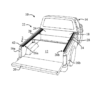
[0017] FIG. 1 illustrates a vehicle 10. The vehicle 10 comprises a bed or
cargo area 12 and a
passenger cab 14. The cargo area 12 may be defined by or may comprise one or
more bed walls
that may include: opposing side bed walls 16a, 16b, a front bed wall 18 that
is located adjacent to
the passenger cab 14, and a rear bed wall or tailgate 20.
[0018] A tonneau cover 22 may be placed over the bed or cargo area 12. The
tonneau cover 22
may include one or more panels 24. While two panels 24 are illustrated in FIG.
1, the tonneau
cover 22 may have any number of panels (i.e., one or more panels). The tonneau
cover 22 may
be attached or supported on one or more tonneau rails, which may be secured or
attached to the
one or more of the bed walls 16a,16b,18,20 defining the cargo area 12. For
example, the tonneau
cover 22 may be supported on first and second tonneau rails 26a, 26b that are
attached to the two
opposing side bed walls 16a, 16b. The first and/or second tonneau rails 26a,
26b may be secured
or attached to one or more accessory rails 32 illustrated in the following
figures.
[0019] While the description in the following figures and paragraphs focuses
on the tonneau rail
26a and the bed wall 16a, it is understood that the teachings can be applied
to attaching a tonneau
rail to any bed wall, including the other side wall 16b, the front wall 18,
and/or the tailgate 20.
The tonneau rail and/or attachment device attached to any of the bed walls may
be a mirror
image of what is shown and disclosed herein.
[0020] With additional reference to FIG. 2, the bed wall 16a may include an
optional bed cap 28.
The bed cap 28 may be a structure that is provided over or on top of a top
surface of the bed wall
16a (and/or on an inside and/or outside wall of the bed wall 16a). The bed cap
28 may be
secured to the top surface of the bed wall 16a with one or more fasteners,
such as one or more
clips 30. However, in certain configurations, the bed cap 28 may be omitted.
For example, lower
end vehicles 10 having fewer options may be free of a bed cap 28, while higher
end vehicles 10
having many options may include a bed cap 28 to improve styling and
aesthetics.
[0021] One or more accessory rails 32 may be attached to the bed wall 16a
and/or to the bed cap
28. The accessory rail 32 may be attached or secured to the bed wall 16a
and/or bed cap 28 via
one or more fasteners 34. The accessory rail 32 may be installed by the
vehicle OEM or as an
aftermarket component by a vehicle owner. The accessory rail 32 may be located
on an inside
surface of the side wall 16a facing the inside of the cargo area 12. The
accessory rail 32 may be
secured to the top surface of the bed wall 16a (surface facing up, which may
include one or more
stake holes), the inside surface of the bed wall 16a (surface facing inside
the cargo area 12), or
3
Date Recue/Date Received 2022-01-26
the outside surface of the bed wall 16a (surface facing outside of the cargo
area 12). The
accessory rail 32 may extend along an entire length of the bed wall 16a,
between the front wall
18 and the tailgate 20 (FIG. 1) or only along a portion of that length. More
than one accessory
rail 32 may be installed on the side wall 16a. For example, two or more
accessory rails 32 may
be installed on the side wall 16a end-to-end to have a single elongated
accessory rail 32 extended
along a length of the side wall 16a. For example, two or more accessory rails
32 may be
installed on the side wall on top of one another such that the two or more
accessory rails 32 are
generally parallel to one another. In other configurations, the one or more
accessory rails 32 may
be installed in a generally vertical orientation, such that the channels 36
extend generally
perpendicular to what is illustrated and described in these figures.
[0022] The accessory rail 32 may have one or more elongated channels 36. The
surface or side
of the accessory rail 32 that faces the inside of the cargo area 12 may have
an opening 38. The
opening 38 may be defined between two inwardly projecting tabs or fingers 40a,
40b. Access
into the channel 36 may be provided through this opening 38. The opening 38
may be defined
along an entire length of the ch ___________________________________________
nnel 36. Alternatively, the opening 38 may be intermediately
defined along the length of the channel 36 and the accessory rail 32 may be
regions where there
are no openings (i.e., the surface or side of the accessory rail 32 that faces
the inside of the cargo
area 12 may have one or more discrete openings 38 vs. an elongated opening 38
as illustrated in
the figures).
[0023] The accessory rail 32 may have an end cap 42 at one or both of the
longitudinal ends of
the channel 36. The end cap 42 may be removed to provide access into the
channel 36 from the
ends thereof. Alternatively, the accessory rail 32 may be free of a cap 42 and
access into the
channel 36 may be provided though the open ends of the channel 36 at the front
and rear ends
thereof. The accessory rail 32 may have a top surface 44 that includes one or
more openings 46
that may provide access into the channel 36. The channel 36 may have a C or U-
shaped cross
section; however, other cross-sections may be envisioned, such as a T-shaped
or mushroom
shaped slot. The channel 36 may also have opposing upper and lower surfaces
78a, 78b.
[0024] One or more accessories may be secured or attached to the accessory
rail 32 or channel
36. The one or more accessories may include one or more cleats, tie downs,
cargo dividers,
attachment devices 48, tonneau rails 26a, etc. The one or more accessories may
be secured to the
accessory rail 32 or channel 36 and thus to the side wall 16a of the vehicle.
The one or more
4
Date Recue/Date Received 2022-01-26
accessories may be configured to secure various cargo to the vehicle or cargo
area and/or provide
a mounting point for securing cargo via one or more chains, straps, ropes,
etc.
[0025] FIGS. 3-5 illustrate an attachment device 48 for engaging the accessory
rail 32 or channel
36. The attachment device 48 comprises a clamp member 50, an anchor 52, and a
fastener 54.
The attachment device 48 may be configured to attach or secure one or more
accessories to the
accessory rail 32.
[0026] The clamp member 50 comprises an attaching member 56 for engaging the
accessory or
tonneau rail 26a (See FIG. 7). The attaching member 56 comprises a finger or
hook 57 for
engaging a corresponding, finger or hook 71 on the engagement portion 70 of
the of the tonneau
rail 26a (FIG. 7). The finger 57 of the attaching member 56 may be downwardly
facing, in
vehicle position. The clamp member 50 comprises one or more bores or apertures
58 for
receiving or engaging one or more fasteners 54. The bore or aperture(s) 58 may
be threaded.
The bore or aperture(s) 58 may be smooth or non-threaded. The clamp member 50
comprises an
engagement feature 60 sized, shaped, and configured to fit within the opening
38 defined in the
accessory rail 32 and engage the channel 36. The engagement feature 60 may be
a flange, boss,
hub, or other projection.
[0027] The anchor 52 is sized, shaped, and configured to fit within the
channel 36. The anchor
52 has a width designed to fit or slide within a height H of the channel 36,
that may be defined
between the two opposing surfaces 78a, 78b (FIG. 2). The anchor 52 has a
height that is defined
between two opposing ends 62 that is larger or longer than the height H of the
channel 36. The
anchor 52 has a projection, hub, flange or boss 64 for engaging the opening 38
defined in the
accessory rail 32. The anchor 52 has a bore 66 for receiving or engaging the
fastener 54.
[0028] The anchor 52 has one or more angled walls 53. Two or more of the
angled walls 53 may
be generally parallel to one another. The one or more angled walls 53 may
function to provide a
wedge effect to jam, secure, or lock the anchor 52 within the channel 36 and
between the two
opposing surfaces 78a, 78b, discussed further below with reference to FIGS. 6-
7.
[0029] The fastener 54 may engage the bores 58, 66 such that by tightening the
fastener 54, the
clamp member 50 and the anchor 52 are brought closer together. By loosening
the fastener 54,
the clamp member 50 and the anchor 52 can be separated or moved apart. The
fastener 54 may
be a threaded member or bolt that threadably engages threads defined in the
bores 58,66. The
fastener 54 may be any fastener and tightened by hand or via a tool, such as a
screw driver. The
Date Recue/Date Received 2022-01-26
fastener 54 may be a quick connect or quarter-turn fastener. The fastener may
have a flat, star,
or torx head. The fastener may be a push fastener, Christmas tree, rivet. The
fastener may be a
Torx button head holt, a Torx 30 Button head bolt, a hex head bolt, or the
like.
[0030] FIG. 6 illustrates the attachment device 48 attached or secured to the
accessory rail 32.
The optional bed cap 28 illustrated FIGS. 2 and 7 has been removed for
clarity. The accessory
rail 32 may be secured to the bed wall 16a of the vehicle 10 via one or more
fasteners 34 (See
also FIG. 2)
[0031] The anchor 52 may be installed inside of the channel 36 by
manipulating, sliding, or
passing the anchor 52 through the opening 38 in the accessory rail 32; by
manipulating, sliding,
or passing the anchor 52 through the opening defined at the front or rear end
of the accessory rail
32 (i.e., by removing the optional end cap 42; FIG. 1); and/or by
manipulating, sliding, dropping,
or passing the anchor 52 through one or more of the openings 46 defined in the
top surface 44 of
the accessory rail 32.
[0032] The flange 64 of the anchor 52 may fit or engage the opening 38 of the
accessory rail 32,
from the inside of the channel 36 to locate and align the anchor 52 within the
channel 36. In
other words, the flange 64 may fit in the opening 38 defined between the two
opposing tabs or
fingers 40a, 40b (FIG. 2) from inside the channel 36.
[0033] The clamp member 50 may be brought into engagement with the accessory
rail 32 by
fitting the engagement feature 60 of the clamp member 50 into the open portion
38 of the
accessory rail 32 from the outside of the ch _______________________________
nnel 36. The engagement feature 60 may fit in the
opening 38 between the two opposing tabs or fingers 40a, 40b (See also FIG. 2)
from outside the
channel 36. This placement of the anchor 52 and clamp member 50 relative to
the opening 38
may generally align the corresponding bores 58, 66 of the clamp member 50 and
the anchor 52
along a common axis to allow the fastener 54 to engage the bores 58, 66 to
connect together the
clamp member 50 and anchor 52. Tightening the fastener 54 (for example, by
turning the
fastener and/or moving the fastener in or out of the bores 58, 66) by may
cause the clamp
member 50 and anchor 52 to move towards each other and sandwich or clamp the
accessory rail
32 or tabs or fingers 40a, 40b therebetween. Tightening the fastener 54 may
also cause the
anchor 52 to partially rotate or turn within the channel 36 such that the
angled walls 53 and/or
ends 62 of the anchor 52 contact or engage the upper and lower surfaces 78a,
78b defining of the
channel 36 (See FIG. 2). This will cause the anchor 52 to wedge itself within
the channel 36 and
6
Date Recue/Date Received 2022-01-26
thus restrict or prevent the anchor 52 from further rotation and/or sliding or
translation along a
length of the channel 36 or otherwise moving in the channel 36. For example,
the anchor 52 may
rotate or turn 5 degrees or more 15 degrees or more within the channel 36, 25
degrees or more
within the channel 36, 35 degrees or more within the channel 36, 45 degrees or
more within the
channel 36, 60 degrees or more within the channel 36, 75 degrees or more
within the channel 36,
or up to 90 degrees within the channel 36 to wedge itself in the channel 36
and then prevent
movement thereof.
[0034] Turning now to FIG. 7, the tonneau rail 26a may then be brought into
position between a
face 68 of the bed cap 28 and the clamp member 50. Alternatively, if there is
no bed cap 28,
then the face 68 may be a side wall or face of the side wall or bed wall 16a
defining the cargo
bed 12. The tonneau rail 26a may have an engagement portion 70 that is
configured to engage or
surround the attaching member 56 or finger or hook 57 of the attaching member
56. The
attaching member 56 engages the tonneau rail 26a in a location above the
channel 36 of the
accessory rail 32. The engagement portion 70 of the tonneau rail 26a may have
one or two
opposing fingers 71 (i.e., first finger and second finger) defining a U or C-
shaped cross section
into or between which the attaching member 56 or finger 57 thereof is
configured to fit or be
received in or between. For example, the bottom finger 71 (i.e., first finger)
may be upwardly
facing and the top finger 71 (i.e., second finger) may be downward facing. The
attaching
member 56 or the downwardly facing finger 57 of the attaching member 56 may
engage the
upwardly facing finger 71 (i.e., first finger) of the engagement portion 70 of
the tonneau rail 26a.
[0035] The tonneau rail 26a may also have a top or engaging surface 72 that
may contact or rest
against a top surface 74 of the bed cap 28 or a top surface of the bed wall
16a if the bed cap 28 is
omitted. The fastener 54 may then be further tightened, which will cause the
anchor 52 and the
clamping member 50 to further sandwich and apply tension onto the accessory
rail 32 or fingers
40a, 40b. The attaching member 56 of the clamp member 50 will press or force
or clamp the
engagement portion 70 of the tonneau rail 26a against the face 68 of the bed
cap 28 or the face
68 of the side wall of the bed wall. In other words, the clamp member 60
presses or clamps or
applies a force onto the tonneau rail 26 so that the tonneau rail 26a is
directly against the bed
wall 16a or indirectly against the bed wall 16a (if the tonneau rail 26a is
against the face 68 of
the bed cap 28). The top or engaging surface 72 of the tonneau rail 26a may be
pressed or
clamped against the top surface 74 of the bed cap 28.
7
Date Recue/Date Received 2022-01-26
[0036] With the tonneau rail 26a now secured to the accessory rail 32 and thus
to the side wall
16a of the vehicle 10, the tonneau cover 22 or panel(s) 24 thereof may be
supported on the
tonneau rail 26a. For example, the tonneau rail 26a may have a ledge or
sealing surface 76 onto
which one or more panels 24 of the tonneau cover 22 may contact or rest on.
[0037] To remove or separate the tonneau rail 26a from the accessory rail 32
or vehicle, the
above steps may be performed in reverse order. For example, the fastener 54
may be loosened,
which will reduce the tension or force applied onto the tonneau rail 26a via
the clamp member
50. The tonneau rail 26a may then be separated from the accessory rail 32 or
vehicle. The
fastener 54 may then be re-tightened to prevent the elements of the attachment
device 48 from
rattling or coming apart. Alternatively, the fastener 54 may be removed from
the bores 66, 58 of
the anchor 52 and clamp member 50, thus allowing the fastener 54 and clamp
member 50 to be
separated from the accessory rail 32 or vehicle. The anchor 52 may remain in
the channel 32, or
the anchor 52 may be removed from the channel 32.
[0038] The vehicle may be any vehicle that has a cargo area or bed. The cargo
area or bed may
be any area or portion of the vehicle used for storing or transporting goods
or cargo. The cargo
area may be any part of the vehicle that has an open top. The open top can be
at least partially
closed or covered by a cover, which may be a trunk, decklid, tonneau cover,
cap, tent, tarp,
board, or a combination thereof. The cargo area may be a cargo box, a bed, a
trunk, or a
combination thereof. The cargo area may also be a trailer that is configured
to be pulled or
pushed by the vehicle.
[0039] The cargo area may be defined by one or more bed walls. The one or more
bed walls
may be a fender, side wall, front wall, a back wall or tailgate, or a
combination thereof. The
accessory rail may be attached to or engage one or more of the walls of the
cargo area. The
accessory rail may engage a top surface of the one or more bed walls, an
inside surface of the
one or more bed walls (i.e., a surface inside of the defined cargo area), an
outside or exterior
surface of the one or more bed walls (i.e., a surface outside of the defined
cargo area).
[0040] The accessory rail may be a device or member that is attached to one or
more of the bed
walls (i.e., side walls, front wall, and/or tailgate). The accessory rail may
be used to attached
various accessories to the vehicle or cargo bed, such as tie down cleats,
hooks, securing
members, ladder racks, etc. The accessory rail may be supplied by the vehicle
manufacturer.
The accessory rail may be installed by the vehicle owner as an after-market
accessory.
8
Date Recue/Date Received 2022-01-26
[0041] The accessory rail may include one or more channels. The channel may
function to
receive a portion of the attachment device, like the anchor and/or part of the
clamp member. The
channel may have a general C or U-shaped cross-section, such that one side is
open to allow a
portion of the clamp member to enter. The channel may include two or more
fingers or tabs
which may function to locate the anchor and clamp member within the locking
channel and
prevent vertical movement the anchor and clamp member.
[0042] The tonneau cover may be any cover or covering. The tonneau cover may
function to
protect against dirt, debris, fluid, and/or other contaminants from entering
an inside of a cargo
area. The tonneau cover may function to conceal the inside of the cargo area
and/or contents
inside the vehicle bed. The tonneau cover may comprise one or a plurality of
panels. The one or
more of the panels can be moved or repositioned relative to one another and/or
relative to the
cargo area to move the tonneau cover between an open configuration and a
closed configuration.
The open configuration is where one or all of the panels are moved to provide
access to the cargo
area. The closed configuration is where one or all of the panels at least
partially cover the cargo
area.
[0043] The one or more panels may be configured to be roll-up into a closed
configuration and
unrolled into the open configuration. The one or more panels may be configured
to be folded-up
into a closed configuration and then unfolded into the open configuration. In
some
configurations, the tonneau cover may be a single panel cover. The single
panel can be raised or
pivoted relative to the walls or top surfaces of the vehicle bed and/or
tailgate to move the
tonneau cover from the closed configuration to the open configuration, and
then lowered or
pivoted downwards to the closed configuration.
[0044] One or more of the panels may be rigid or substantially rigid. One or
more of the panels
may be flexible or substantially flexible but stabilized with a rigid frame.
One or more of the
panels may be plastic or metal slats. The tonneau cover may be a canvas,
fabric, a folded, or
roll-up type tonneau cover. In some configurations, the tonneau cover may also
be a truck cap or
tent or other cover that increases a height of a cargo area.
[0045] The tonneau rail system may include one or more tonneau rails. A
tonneau rail comprises
structure to attach or support the tonneau cover to the vehicle or vehicle bed
or cargo area. The
tonneau rail may function provide support for a tonneau cover to rest on when
the tonneau cover
or one or more panels are in the open or closed position. The tonneau rail may
extend at least
9
Date Recue/Date Received 2022-01-26
partially along a length of one or more of the bed walls or accessory rails.
The tonneau rail may
be an elongated component that is made of aluminum, metal, plastic, or a
combination thereof.
The tonneau rail may have virtually any structure configured for supporting a
tonneau cover in
the open and/or closed position.
[0046] A tonneau rail system may include one or more of the following
elements: tonneau
cover, one or more panels, one or more tonneau rails, one or more accessory
rails, one or more
attachment devices.
[0047] The tonneau rail system may include one or more attachment devices. The
one or more
attachment devices may provide a mount or support or sufficient structure to
support the tonneau
rail and/or to attach or secure the tonneau rail to the bed wall or accessory
rail. The attachment
device may allow the tonneau rail to be attached or secured to the bed wall
without drilling or
adding additional holes through the tonneau rail, accessory rail, and/or bed
wall. The attachment
device may be used to support or attach one or more other accessories to the
vehicle, accessory
rail, or both. A plurality of attachment devices may be used to support a
single tonneau rail to
the accessory rail or bed wall.
[0048] The attachment device may include one or more clamp members. A clamp
member may
function to secure the one or more accessories to the accessory rail. The
clamp member may be
in contact with the accessory and the anchor. The clamp member may be made of
any suitable
material, such as plastic, metal, aluminum. The clamp member may secure the
accessory above
the accessory rail or channel of the accessory rail. The clamp member may
secure the accessory
below the accessory rail or channel of the accessory rail. The clamp member
may be capable of
slightly bending or deflecting to secure the accessory to the accessory rail
or side wall.
[0049] The attachment device may include one or more anchors. The anchor may
be made of
plastic, steel, composite, or a combination thereof. The anchor may be square,
rectangular,
triangular, circular, trapezoidal, or any other suitable shape. The anchor may
have one or more
holes or bores for receiving one or more of the fasteners. The anchor may have
one or more ends
or surfaces. The one or more ends or surfaces may be curved, straight, or
flat. The one or more
ends may engage the channel to lock or wedge the anchor therein to prevent
further moment of
the anchor. The surface of the one or more ends may be smooth or textured to
provide additional
gripping inside of the channel.
Date Recue/Date Received 2022-01-26
[0050] The attachment device may include one or more fasteners. The fastener
may function to
attach the anchor and the clamp member to the bed wall or accessory anchor.
The fastener may
be made of plastic, metal, composite, or a combination thereof. The fastener
may be threaded.
The fastener may be smooth. The fastener may be a screw, a bolt, a pin, a
rivet, a push fastener, a
push pin, a nail, a weld, a projection, or another suitable fastener known in
the art. The fastener
may be self-tapping. Self-tapping means that the fastener is configured to cut
or otherwise form a
thread in the component or element into which hit is received or driven. The
fastener may be
expandable. The fastener may be configured to be reversible such that the
fastener can be
tightened and loosened to assemble and disassemble the system with damaging
the tonneau rail,
accessory rail, clamp member, etc. The fastener may be configured to be
irreversible such that
the fastener cannot be loosened after initially tightening the fastener
without damaging the
tonneau rail, accessory rail, clamp member, etc. The fastener may be tightened
with a tool (i.e.,
screw driver, rachet, plyers, etc.). The fastener may have a Philips, flat,
torx, start head. The
fastener may be tightened by hand.
100511 The explanations and illustrations presented herein are intended to
acquaint others skilled
in the art with the invention, its principles, and its practical application.
The above description is
intended to be illustrative and not restrictive. Those skilled in the art may
adapt and apply the
invention in its numerous forms, as may be best suited to the requirements of
a particular use.
[0052] Accordingly, the specific embodiments of the present invention as set
forth are not
intended as being exhaustive or limiting of the teachings. The scope of the
teachings should,
therefore, be determined not with reference to this description, but should
instead be determined
with reference to the appended claims, along with the full scope of
equivalents to which such
claims are entitled. The omission in the following claims of any aspect of
subject matter that is
disclosed herein is not a disclaimer of such subject matter, nor should it be
regarded that the
inventors did not consider such subject matter to be part of the disclosed
inventive subject
matter.
100531 Plural elements or steps can be provided by a single integrated element
or step.
Alternatively, a single element or step might be divided into separate plural
elements or steps.
[0054] The disclosure of "a" or "one" to describe an element or step is not
intended to foreclose
additional elements or steps. For example, disclosure of "a motor" does not
limit the teachings to
a single motor. Instead, for example, disclosure of "a motor" may include "one
or more motors."
11
Date Recue/Date Received 2022-01-26
[0055] While the terms first, second, third, etc., may be used herein to
describe various elements,
components, regions, layers and/or sections, these elements, components,
regions, layers and/or
sections should not be limited by these terms. These terms may be used to
distinguish one
element, component, region, layer or section from another region, layer or
section. Terms such as
"first," "second," and other numerical terms when used herein do not imply a
sequence or order
unless clearly indicated by the context. Thus, a first element, component,
region, layer or section
discussed below could be termed a second element, component, region, layer or
section without
departing from the teachings.
[0056] Spatially relative terms, such as "inner," "outer," "beneath," "below,"
"lower," "above,"
µ`upper," and the like, may be used herein for ease of description to describe
one element or
feature's relationship to another element(s) or feature(s) as illustrated in
the figures. Spatially
relative terms may be intended to encompass different orientations of the
device in use or
operation in addition to the orientation depicted in the figures. For example,
if the device in the
figures is turned over, elements described as "below" or "beneath" other
elements or features
would then be oriented "above" the other elements or features. Thus, the
example term "below"
can encompass both an orientation of above and below. The device may be
otherwise oriented
(rotated 90 degrees or at other orientations) and the spatially relative
descriptors used herein
interpreted accordingly.
[0057] The invention illustratively disclosed herein suitably may be practiced
in the absence of
any element which is not specifically disclosed herein.
[0058] Any of the elements, components, regions, layers and/or sections
disclosed herein are not
necessarily limited to a single embodiment. Instead, any of the elements,
components, regions,
layers and/or sections disclosed herein may be substituted, combined, and/or
modified with any
of the elements, components, regions, layers and/or sections disclosed herein
to form one or
more embodiments that may be not be specifically illustrated or described
herein.
[0059]
12
Date Recue/Date Received 2023-04-26