Note: Descriptions are shown in the official language in which they were submitted.
CA 03147007 2022-01-11
WO 2020/013830
PCT/US2018/041908
VAGINAL TEMPERATURE SENSING APPARATUS AND METHODS
TECHNICAL FIELD
This invention relates to devices and processes for sensing and using body
temperature to
predict ovulation events for a user.
BACKGROUND
As has been well known for years, a woman typically may monitor and record her
body
basal temperature on a daily basis by way of inserting a thermometer into her
vagina and recording
her temperature. As a result of this perhaps complex daily procedure, a woman
may be likely to
forego recording her more accurate core temperature obtained vaginally and
instead may keep
track of her oral temperature. Furthermore, although temperature monitoring
may have been used
for years to help determine a fertile phase of a woman, the pattern
recognition and relationship of
temperature variation may not have been practically achieved such as due
perhaps to the lack of
frequent temperature monitoring and statistical analysis of baseline core body
temperature. Other
methods of obtaining a woman's body temperature over time may include frequent
temperature
measured orally or from her axilla, however there may be accuracy issues, and
frequent insertion
of a wired rectal probe or vaginal probe may be inconvenient and
uncomfortable. Hence there has
long been a need for improved methods, systems, and apparatuses for obtaining
an accurate basal
temperature vaginally while reducing inconvenience and discomfort; in-situ
vaginal temperature
sensing was conceived in response to such disadvantages.
Indeed, in-situ vaginal temperature sensing apparatus and methods are known.
However,
they are not without limitations with respect to battery life, manufacturing,
and operation. For
example, user confidence in device operation may be compromised in certain
ways due to user
uncertainty about whether the device is actually in an operational mode while
it is located in the
.. vagina vault. Current manufacturing processes may be protracted or rendered
prohibitively
expensive in an effort to mitigate the negative effect of high temperatures
used during
manufacturing process heating profiles (used to cure device materials such as
silicone) on batteries,
including on their amp-hour capacity. Further, batteries used in vaginal
temperature sensing rings
are, of necessity, exceedingly small, and accordingly have a very limited amp-
hour capacity; any
technology that conserves battery power is a welcome improvement.
1
CA 03147007 2022-01-11
WO 2020/013830
PCT/US2018/041908
Due to the use of the device in the vagina, the surface of the insertable
device may
preferably be smooth, such as with no seams or crevices to trap biological
matter, and there may
be no protruding parts, such as may injure the user. This may require that the
switch be sealed
into the device during silicone molding. Reed switches, which are actuated by
a magnet placed
near the switch (e.g. within 6mm), often may be used as switches in sealed
devices. Some sealed
devices utilize a normally closed reed switch that is in the open state only
when a magnet is held
nearby such that the magnetic field holds the switch open. One example of such
a device is the
PillCamTM. In these devices utilizing a normally closed reed switch, a magnet
may be placed near
the switch as soon as the device is manufactured and held there until the
device is packaged. Once
the device is packaged, a magnet can be held in place at the proper location
relative to the device
by the package design. When the device is removed from the package, it may be
moved away
from the magnet, perhaps causing the reed switch to close, and the device may
be turned on. This
normally closed reed switch method may have the disadvantage that special
fixturing and handling
may be required to keep magnets near the reed switch once the batteries are
inserted during
manufacturing and until they are placed in the final packaging containing a
magnet. An advantage
may be that it may be very simple for the end-user to turn the device on, such
as by merely
removing the device from the package.
Another aspect of ovulation prediction is desire for increasing accuracy and
time of
indication. Traditional systems rely on basal temperature activity to make
their determinations.
.. This is largely based on the fact that daytime, diurnal temperatures are
notoriously noisy and
subject to activity and other being-awake temperature impacts. Many
improvements in basal
temperature processes have been pursued and yet a desire for even better
indications remains.
Further, there has been a desire for systems that can better satisfy user
desires as well as improve
with use as a system learns any peculiarities of that particular user or gains
overall user
experiences.
Accordingly, particular embodiments of the inventive technology address one or
more of
these concerns by conserving battery power by reducing its consumption during
non-use of the
device; enabling a user can reliably, quickly and easily determine whether the
device is powered
on, e.g., during insertion or removal of the device by a user; and/or
providing a more efficient, two
step curing process; and providing earlier and better indications that a user
desires. Of course, the
2
CA 03147007 2022-01-11
WO 2020/013830
PCT/US2018/041908
inventive technologies that achieve each of these can be combined in any
manner. Other
advantages may be indicated elsewhere in this specification.
DISCLOSURE OF THE INVENTION
Embodiments of the various aspects of the inventive technology may include one
or more
of the following: methods and related apparatus that avoid harming or reducing
power of
battery(ies) of a vaginal temperature sensing device during its manufacture;
apparatus and related
methods that allow for user determination that a vaginal temperature sensing
device is in a power-
on mode; and apparatus and related methods that conserve battery power of an
in-situ vaginal
temperature sensing ring. They may also provide systems that avoid the
traditional basal
temperature approach, compare different approach to more appropriately satisfy
a user, and even
are in themselves intelligent to improve their capabilities. Of course,
embodiments may involve
combinations of one or more of such aspects, in any combination or
permutation.
BRIEF DESCRIPTION OF FIGURES
Fig. 1 shows an embodiment with the device in packaging, including a switch
reconfiguration site,
in its "during shipment" location.
Fig. 2 shows manual placement by a user of the device from its shipment
location to the switch
reconfiguration site, in the embodiment shown in Fig. 1.
Fig. 3 shows an open device mold, with the insert displaced from the relative
position it holds
during a first of two moldings, the first used to mold an outer shell in
particular embodiments of
the inventive technology.
Fig. 4 shows an open device mold of Fig. 3, with the insert in the relative
position it holds during
the first of two moldings, in particular embodiments of the inventive
technology.
Fig. 5 shows the mold of Figs. 3 and 4 in closed position, as it would appear
during at least the
first molding, in particular embodiments of the inventive technology.
Fig. 6 shows a cross-section from the side of a mold, with insert, and first
material between the
insert and the mold, as may appear in the first molding in particular
embodiments of the inventive
technology.
3
CA 03147007 2022-01-11
WO 2020/013830
PCT/US2018/041908
Fig. 7 shows a transparent, perspective view of the device after a first
molding, with mold insert
still in position, before its removal from the cured outer ring shell, as may
appear in particular
embodiments of the inventive technology.
Fig. 8 shows how electrical componentry may be inserted into the cured outer
ring shell after the
mold insert is removed therefrom, as may be seen in particular embodiments of
the inventive
technology.
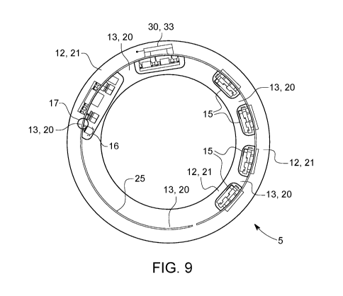
Fig. 9 shows a transparent top view of the device as may appear in particular
embodiments of the
inventive technology.
Fig. 10 shows a perspective view of the device as may appear in particular
embodiments of the
inventive technology.
Figs. 11A and 11B shows views from both sides of electrical componentry as may
appear in
particular embodiments of the inventive technology.
Fig. 12 shows a view from one side of electrical componentry as may appear in
particular
embodiments of the inventive technology. It shows a flexible printed circuit
substrate design with
two short rigid sections and two flexible sections as may appear in
embodiments of the inventive
technology.
Fig. 13 shows a block diagram of an electrical schematic as may appear in
particular embodiments
of the inventive technology.
Fig. 14 shows a block diagram of an electrical schematic as may appear in
particular embodiments
of the inventive technology.
Fig. 15 shows an image (a screen shot) from a cellphone app that instructs
users as to how to
reposition the vaginal temperature sensing ring to a switch reconfiguration
site (a cradle as appears
in packaging in the embodiment of Figs. 1 and 2) in order to activate the ring
so that a
communication between it and an external device such as a cellphone may be
established.
Fig. 16 shows possible dimensions of a vaginal temperature sensing ring as may
appear in
embodiments of the inventive technology.
Fig. 17 depicts and overall system to show where programming routines and
processing or
firmware may be located and activity achieved.
Fig. 18 is a schematic of one of the potential configurations with
programming, subroutines,
firmware, and processing capabilities shown in differing embodiments that may
be combined.
4
CA 03147007 2022-01-11
WO 2020/013830
PCT/US2018/041908
Fig. 19 shows actual temperature data as well as transformed and recalculated
values to achieve
some goals of differing embodiments of the invention.
MODE(S) FOR CARRYING OUT THE INVENTION
As mentioned earlier, the present invention includes a variety of aspects,
which may be
combined in different ways. The following descriptions are provided to list
elements and describe
some of the embodiments of the present invention. These elements are listed
with initial
embodiments; however, it should be understood that they may be combined in any
manner and in
any number to create additional embodiments. The variously described examples
and preferred
embodiments should not be construed to limit the present invention to only the
explicitly described
systems, techniques, and applications. The specific embodiment or embodiments
shown are
examples only. The specification should be understood and is intended as
supporting broad claims
as well as each embodiment, and even claims where other embodiments may be
excluded.
Importantly, disclosure of merely exemplary embodiments are not meant to limit
the breadth of
other more encompassing claims that may be made where such may be only one of
several methods
or embodiments which could be employed in a broader claim or the like.
Further, this description
should be understood to support and encompass descriptions and claims of all
the various
embodiments, systems, techniques, methods, devices, and applications with any
number of the
disclosed elements, with each element alone, and also with any and all various
permutations and
combinations of all elements in this or any subsequent application.
One aspect of the inventive technology focuses on a two step molding process
(e.g., with
a first molding and a distinct second molding that occurs later) that may use
two different materials,
each perhaps being curable at different temperatures. As mentioned, in some
embodiments, the
electronic circuitry, including batteries, may be molded in a medical grade
silicone. Medical grade
silicones with the proper durometer, tensile strength and tear strength that
may be required by the
device may require curing at a high temperature, for example at 125 C. Lower
temperatures may
be used but as the cure temperature is decreased the cure time may be
extended. The batteries used
in the device may be very small, such as to enable it to meet dimensional
requirements. Batteries
this small may have been developed for watches and hearing aids. There may not
have been any
requirement for these types of batteries to be able to survive or maintain amp-
hour capacity after
5
CA 03147007 2022-01-11
WO 2020/013830
PCT/US2018/041908
exposure to high temperature. A typical battery of this type may be only rated
to survive an
exposure to 60 C. At 60 C, the medical grade silicones that may have necessary
properties may
take many hours to cure, perhaps causing the manufacturing process to be too
slow and expensive.
A solution to this problem may be a two-step molding process perhaps using a
first material
(6) (e.g., a first cure temperature material (12)) and a second material (11)
(e.g., a second cure
temperature material (13)). The first step may be to mold an outer shell in a
mold (7), such as using
a strong, high temperature cure medical grade silicone (a type of first cure
temperature material).
Since this step may be done without the electronics (which include the battery
(15), a term that
includes one or more battery/ies), the outer shell may be cured at a high
temperature (e.g., the high
maximum temperature observed during such first cure). The shape of this cured,
flexible, outer
shell (8) (e.g., ring shell) may be chosen such that it may fit snugly around
the electronic assembly
(a snug fit may be observed even where voids exist between the installed
electronics and the shell
at any time after installation of the electronics. The electronic assembly (or
perhaps a portion of
it or its componentry) with, inter alia, battery(ies), where such assembly may
also be flexible (e.g.,
.. a small width, longer length, flexible circuit board), may be then inserted
into the outer shell (e.g.,
through an access opening (9)). In perhaps a final step (perhaps performed
while the outer shell
is still in its mold, but not necessarily), lower strength, low temperature
curing silicone (a type of
second cure temperature material) may be injected into the outer shell, such
as to fill at least a
portion of voids (between the outer shell and the electrical componentry
installed therein). This
second silicone may be transparent and a small section may be exposed on the
inner diameter (e.g.,
perhaps filling a window (17) that is established, e.g., via cutting, through
the ring), such as to
allow the LED to be seen (perhaps as described elsewhere herein). Note that at
least a portion of
voids could be at least a significant portion of the voids (i.e., at least
20%, by volume), at least a
majority portion of voids, or substantially all voids (90% or more). Where
only a portion of the
voids are filled, it may be that the opening is fully and reliably sealed
(e.g., with the second cure
temperature material), separating voids within the ring from the outside
environment.
Accordingly, particular embodiments of the inventive technology may be
described as a
method of manufacturing a vaginal temperature sensing ring (5), and may
include the steps of:
establishing (e.g., via injection or other known insertion technique) first
material in a mold (7);
curing the first material in the mold at a first heating profile having a
first maximum cure
temperature, to form a cured, flexible, outer ring shell (8); and establishing
an access opening (9)
6
CA 03147007 2022-01-11
WO 2020/013830
PCT/US2018/041908
in said cured, flexible, outer ring shell. Like all heating profiles used
during device manufacturing,
the profile (temperature vs. time graph) may be linear or non-linear, using
variable temperatures
or constant temperature. The maximum cure temperature is the temperature at
which the materials
are actually cured; they are the maximum temperatures observed during the
respective heating
profiles and can be higher than the lowest temperature of the range at which
the materials are
curable. Even a constant temperature heating profile has a maximum
temperature; it is the constant
temperature used.
The access opening (9) may be, as but one example, a circumferential slit (14)
along the
inside or outside circumference of ring-shaped embodiments (including a cut
along all or a
majority portion of such embodiments). As but one of many additional
embodiments, other access
openings may be along the circumference at the top or bottom of ring shaped
embodiments (where
top and bottom refer a device when laid on a horizontal surface). For an
opening to be
circumferential, it need not be along the entire circumference. Note that the
step of establishing
an access opening (9) in the cured, flexible, outer ring shell (8) can either
be performed during
performance of the step of curing the first temperature material in the mold
(7) (the mold would
be shaped to form the access opening), or after performance of that step
(e.g., where the cured,
flexible, outer ring shell is cut to form, e.g., a circumferential slit along
its inner circumference).
Additional steps may include inserting temperature sensing electrical
componentry through
the access opening (9) and into the cured, flexible, outer ring shell (8)
establishing second material
within the cured, flexible, outer ring shell (e.g., via injection or other
known insertion technique)
to fill at least a portion of voids between the temperature sensing electrical
componentry and the
cured, flexible, outer ring shell (thereby perhaps embedding such componentry
in the second cure
material); and curing the second material at a second heating profile having a
second maximum
cure temperature, wherein the second maximum cure temperature is lower (e.g.,
by at least 10%,
at least 15%, at least 20%, at least 25%, at least 30%, at least 35%, at least
40% or at least 50%)
than the first maximum cure temperature. The "at least a portion of voids"
could be at least a
significant portion (i.e., at least 20%), at least a majority portion (i.e.,
at least 50%), or substantially
all voids (i.e., at least 90%). Note that the manner of inserting temperature
sensing electrical
componentry through the access opening (9) may depend on the type of access
opening. For
example, where it is an inner circumferential slit (as shown in Fig. 8), it
may involve positioning
the componentry (e.g., an assembly, such as components strung together to form
an electrical
7
CA 03147007 2022-01-11
WO 2020/013830
PCT/US2018/041908
circuit string) near and interiorly of the slit and then forceibly inserting
the assembly through the
slit, which may be held in open position by a tool. Where the access opening
is a smaller hole,
perhaps a pull string is molded into the circumferential void of the cured
outer ring shell, with both
ends passing through the access opening; this pull string can then be
connected to the electrical
componentry (e.g., to one end of an assembly in the form of an electrical
circuit string) and pulled
through so that the electrical componentry is/are established in the cured,
outer ring shell (likely
with voids between the componentry and the cured, outer ring shell in which
it/they rest(s)). The
smaller hole can be, e.g., just large enough to pull the electrical
componentry through it.
Steps, from the beginning, followed in manufacturing at least one embodiment
of the
vaginal temperature sensing apparatus may include one or more of the
following: place a mold
insert (40) into a cavity defined by at least part of remaining parts of the
mold (note that the mold
insert, a part of the mold, may, inter alia, help to create cavities within
the shell within which
electronics may be installed); close mold (including perhaps tightening of
bolts to keep mold
closed, with its components in proper relative position); preheat mold (e.g.,
to 59 C); inject (e.g.,
hand inject) first cure temperature material (e.g., MED 4950 silicone) into
mold (e.g., via injection
into a mold gate until the first temperature material exits the mold vent
(exemplary pressure may
be 80 psi), perhaps after mold is removed from heating equipment; place mold
(with, e.g., silicone
thereon) back into heating equipment for, e.g., 6 mins at 205 C; allow mold
and injected material
to cool; remove silicone from gate and vent holes; open mold; remove silicone,
with embedded
insert from remainder of mold (e.g., from clamshell portions of mold),
referred to as a ring part;
hand trim silicone flash from outside of ring; hand trim interior flash by
cutting close to the center
of the ring and insert; pull silicone ring off of insert, said ring having an
interior space substantially
along its annular centerline, and a circumferential slit/opening at the inner
circumference of the
ring (of course, however, such slit/opening could be established elsewhere,
e.g., along the outer
circumference of the ring, or along the top or bottom circumference (e.g.,
substantially the highest,
circumferential "ridge" or the lowest circumference, i.e., that portion that
may contact an
underlying surface when the ring is laid flat), or any circumference anywhere
between any of such
circumferences). After such steps are performed, one may have a cured,
flexible outer (ring) shell
(i.e., without electronics in it).
Additional steps may be as follows: the cured, flexible outer ring shell (8)
may be wiped
with, e.g., isopropyl alcohol; the ring may then be opened at the access
opening (9), e.g., where
8
CA 03147007 2022-01-11
WO 2020/013830
PCT/US2018/041908
the two opposing edges at the access opening are forced apart, and electronics
(e.g., an assembly)
is installed so it (or sub-component(s) of it, such as battery(ies) (15),
PCB's) fits in any
pockets/cavities created by the mold (e.g., by the insert); using a Q-Tip,
e.g., coat entire inside of
ring and electronics with a primer such as MED 160 Nusil Silicone Primer; pre-
fill battery cavities
only, with MED4-4220 silicone (a second material); fill ring with silicone
adhesive (another type
of second material); place ring in mold (in clamshell mold, without insert,
where a clamshell type
mold is used, orienting main circuit board with gate; close mold and tighten;
fill mold (e.g., via
injection, such as manual injection, here actual injection pressure may be
unknown) with Nusil
MED4-4220 silicone adhesive (a type of second material) until it flows out of
vent to fill
substantially all voids within the cured outer shell; place mold on heated
press and heat at 59 C
for 12 minutes (a lower intensity heating profile than that used for curing
the first cure temperature
material); and open mold and remove part from mold (perhaps after first hand
trimming flash).
Such steps may result in a ring device with electronics inserted therein, and
in a device that, but
for any componentry that is external of the ring (e.g., part of the (possibly
substantially error-free)
user-initiated device activation componentry (30)), and any packaging, is
substantially ready for
sale. Note that all steps indicated as manual could be accomplished in another
manner, e.g.,
robotically.
More specifically as to the electrical assembly (electrically connected
electrical
componentry), as in any embodiment, may be vaginal temperature sensing
electrical componentry,
such as including a battery (15), vaginal temperature sensor (24), wires
(perhaps in the form of
conductive connections such as traces between other electrical components),
possibly (wireless)
signal receiver (28) (e.g., an antenna (25) and associated componentry, for
receiving wireless
signal commands from a user to, e.g., send data), switch componentry and data
transmission
componentry (e.g., to send temperature-related data, whether at a pre-
determined time and/or when
commanded by an external communication device such as a cell phone).
Componentry as used
herein may refer to all electrical components, or merely only one component or
a larger portion of
all components; assembly implies some sort of electrical connection between
such components).
In certain embodiments, componentry may include batteries, power conditioning
electronics (e.g.,
power conditioning board), sensor electronics (including a sensor), digital
electronics, RF
electronics, trace antenna (25), switch componentry, perhaps as (substantially
error free) user-
initiated device activation componentry (30) or part thereof, with connections
thereamong as
9
CA 03147007 2022-01-11
WO 2020/013830
PCT/US2018/041908
appropriate (see, e.g. Figs. 11A and 11B). In particular embodiments, certain
componentry may
be established on or to include a sensor, digital electronics and radio PCB.
Circuitry may be
established as part of a flex circuit, i.e., one whose function is not
compromised by the flexing that
may be observed when the device (e.g., ring) in which the circuitry may be
embedded and of which
it may form a part is bent (e.g., upon insertion into a vaginal vault). Note
that, particularly with
respect to those embodiments that include user-initiated device activation
componentry (30),
portion(s) of such componentry may be established outside/externally of the
device (e.g., the ring),
e.g., in the packaging.
In some embodiments, the device flexible circuit substrate design may include
two rigid
sections, located such that when the flex circuit is curved into the ring
shape, they may be spaced
180 degrees apart. The length of each of the rigid sections may be short
enough such that when
the device is flexed it may meet the standards for bend radius and percent
compression, for
example, as established in ISO Standard 8009 (2014) "Mechanical contraceptives
-- Reusable nati iral and
silicone rubber contraceptive diaphrags-is -- Requirements and tests." For
some embodiments, the maximum
length of a rigid section that meets these criteria was determined to be 17mm.
Even when very
small surface mount and chip scale packaged components are used, placing all
the circuitry and
batteries on one rigid section may cause the section to be longer than 17mm
and therefore one
longer rigid section might not meet the standards mentioned above in these
situations.
The electrical componentry may also include a visually sense-able (capable of
being
visually sensed), battery power-on indicator (16) (e.g., a LED that is
lighted, whether blinking or
otherwise, when any amount of battery power, even only sleep mode power, is
drawn). Such may
help to avoid mis-readings, and improve user confidence in the device and data
produced thereby.
Transparent material (20), such as low (second) cure temperature material may
be used in the
proximity of the battery (a term that includes a plurality of electrically
connected batteries) and
may be used to fill at least a portion of any voids between the inserted
electrical componentry (e.g.,
batteries and electrical componentry) and the flexible outer ring shell. It
may also be established
between the installed indicator and an outwardly exposed surface of the device
(at that location)
so that the visually sense-able indicator can be visually sensed (e.g., seen)
by a user. A
manufacturing step that may enable the intentional establishment (e.g.,
placement) of such
transparent material (20) so as to allow a user to see the visually sense-able
battery power-on
CA 03147007 2022-01-11
WO 2020/013830
PCT/US2018/041908
indicator (16) is the creation of a window (17) (whether by, e.g., cutting,
drilling or punching of a
portion of the cured ring shell, or by molding that window during the first
cure through use of the
mold). Transparent material (20) (which may be second cure temperature
material) may be be
established in that window 17 (e.g., via injection, etc.) at some point after
the first cure but before
the second to create a transparent material filled window. Of course,
manufacturing steps should
consider the location of the window, the location of the indicator on the
assembled circuit, and the
orientation of the circuitry during installation so that the visually sense-
able indicator, after
installation, is at the window. The window may be a small window (i.e., with a
radius that is less
than 20% a characteristic radius (e.g., radius where the ring is circular;
average radius where it is,
e.g., oval or elliptical) of an unbent ring. It may be: just large enough to
allow light from the
indicator to pass through it to outside of the vaginal temperature sensing
ring, and/or just large
enough to allow injection therethrough it of the transparent, vaginal ring
material (20).
A first material (6) is typically used during the first of two distinct cures,
and a second
material (11) is typically used during the second cure. Note that the first
and second materials may
indeed be the same type of material, perhaps even having a range of
temperatures and curing
profile that are identical. Indeed, the most striking feature of the inventive
technology is the use
of two distinct curing steps (one with the first material, and the second with
the second material),
and not whether the two materials are different. However, the second material
may indeed have a
different range of materials at which it is curable than the first material,
and may be curable at a
temperature that is lower than the temperature at which the first material is
curable (note that such
cure temperatures may be temperatures that material specifications show are
required to
sufficiently cure the respective material under constant temperature heating
profiles of equal
duration, and may be different from maximum temperatures used in the
respective heating profiles
actually used). As such the first material (6) may be a first cure temperature
material (12) and the
second material (11) may be a second cure temperature material (13). It should
be understood that
any particular curable material may be curable within a range, and where at
least a lower portion
of that range is at or below the highest temperature that batteries can
survive (without unacceptable
degree of damage/loss of capacity, etc.), it is possible that embodiments of
the two-step curing
procedure could use the same curable material for each step such that the
first material is the same
type of material as the second material. However, the maximum cure temperature
of the second
cure step is typically lower than the maximum cure temperature of the first
cure step, and no greater
11
CA 03147007 2022-01-11
WO 2020/013830
PCT/US2018/041908
than the highest temperature that a battery can endure without unacceptable
impairment or damage.
Note that while certain embodiments may indeed include identical curable
materials for the first
and second moldings, it may be preferred to use different materials (which may
indeed have
different cure temperatures) because it may be preferred that, e.g., the first
cure temperature
material, once cured, has, e.g., a higher tensile stress than the second cure
temperature material
and/or only materials with different cure temperatures offer the manufacturing
efficiency
advantages (e.g., speed during curings) sought by certain embodiments.
A first cure of a pre-completion device that lacks a battery (and indeed
perhaps any
electrical componentry) allows the use of a higher maximum curing temperature,
and if preferred,
a material (a first cure temperature material) that cures at a higher cure
temperature (such as a
maximum cure temperature) than (and this is of different type than) the
material used for the
second cure (a second cure temperature material); the following, second cure,
where heating of the
battery was unavoidable, will typically use a lower maximum cure temperature
(and perhaps a
material with a different range of curing temperature than the first
material). Note again, however,
that while it may be preferred that the first material is of different type
(and has a different curing
temperature range) from the second material (i.e., the first material is a
first cure temperature
material and the second material is a second cure temperature material), in
certain other
embodiments, it may be that the first temperature material is the same type of
material (e.g., the
same medical grade silicone) as the second temperature material.
Advantages of segregating the cures into a two cure step process, with each
step using
different heating profiles, may include one or more of the following:
reduction or avoidance of
heat caused injury to battery, faster first cure time, faster overall
manufacturing time, and/or ability
to use stronger tensile strength material for the curing of the outer ring
shell (during the first cure).
As such, the following characteristics may apply to the two materials that are
cured in the
first and second cures, when the materials are different type materials: first
material may have a
higher tensile strength (once cured) than the second material; the second
material may be
transparent while the first material may be opaque (e.g., it may be non-
transparent vaginal ring
material (21), perhaps to prevent visual recognition of electronic
componentry, which a user may
find disconcerting, given that the device is inserted into the human body);
and second material
may be second cure temperature material that is curable at a lower temperature
than is the first
material, which may be first cure temperature material; the first material and
the second material
12
CA 03147007 2022-01-11
WO 2020/013830
PCT/US2018/041908
may each a type of silicone; both curable materials, and at least the first
temperature curable
material may meets International Standard ISO 8009 (2004) and/or ISO 8009
(2014) requirements
(related publications cited and incorporated herein) when the device is to be
worn intra-vaginally;
and the first and/or the second material may be medical grade material, may be
medical grade
plastic, or may be thermoplastic. Further, each may be a type of flexible, non-
conductive vaginal
ring material, and as the first (cure temperature) material may be cured to
form the outer ring shell,
it may be a cured, flexible, outer ring shell material (22); the second (cure
temperature) material,
given that it may be used, inter alia, to fill at least a portion of the space
between installed electrical
componentry and the outer ring shell, may be referred to as void filling
(internal ring) material.
The second cure may be one of the final steps in manufacture, if not, the
final step. The
manufactured device may have a ring shape (e.g., a toroidal shape, a circular
shape, an oval shape,
elliptical shape, closed curvilinear shape, diamond ring shape, wedding band
shape, kettlebell
shape, or polygonal shape, all whether in one plane or not). Note that the
device may be shaped
so that it occupies one plane, i.e., it is flat (ignoring its height) before
user-insertion into a vagina,
but that when pinched immediately before insertion, and effectively, while in
inserted condition,
might not be flat, not unlike a pinched rubber 0-ring. In particular
embodiments, it may be
elastically biased towards the shape it occupies before insertion, e.g.,
unbent (possibly flat) shape;
in others, it may be biased towards the shape it occupies after insertion.
Notable is the possible
location of certain electrical components, such as any antenna (25) that is
used, as such antenna in
certain embodiments may be established substantially along the entire
circumferential length of
the ring (e.g., substantially along at least 90% of the curved circumferential
centerline of the ring),
or substantially at only a localized portion of it (e.g., along less than 30%,
less than 25%, less than
20%, less than 15%, less than 10%, or less than 5%), as may be seen where an
antenna is fit into
a box or container established at less than 15% of the curved ring centerline.
Indeed, in certain
embodiments, all electrical componentry may be contained in such localized
portion. Accordingly,
it should be understood that the inventive technology is not limited merely to
those designs where
electrical componentry, such as an antenna, is established substantially along
the entire
circumferential length of the ring. Indeed, in the various manifestations of
the inventive
technology, electrical componentry (such as, but not limited to, any antenna
that is used) can be
established almost anywhere with respect to the non-conductive material (e.g.,
silicone) in which
that componentry may be established ¨ electrical componentry can be
distributed along the
13
CA 03147007 2022-01-11
WO 2020/013830
PCT/US2018/041908
circumferential length of the device or can be "bunched" or packaged together
at only a localized
portion of it. In such designs, such might cause the device to have an
increased width (e.g.,
difference between outer and inner radii), although this is not a required
feature in such designs.
A vaginal temperature sensing ring (5) may be described as including: a cured,
flexible,
outer ring shell (8) made of first material; temperature sensing electrical
componentry established
in the cured, flexible, outer ring shell; and cured second material
established within the cured,
flexible, outer ring shell and between the temperature sensing electrical
componentry and the
cured, flexible, outer ring shell. As mentioned, the second cured material and
the cured, flexible,
outer ring shell may have been cured during two distinct cures (indeed, such
may be discerned
from a distinct boundary between the two materials, after the final cure is
entirely completed,
where such boundary is an interface of three dimensional surfaces of the two
cured materials).
Such materials may be identical, or instead may be a first cure temperature
material and a second
cure temperature material.
An independent but potentially related aspect of the inventive technology may
focus more
on the use of transparent material, such as to allow for visual recognition of
a visually sense-able,
battery power-on indicator (16) (e.g., a light, such as but not limited to a
LED) that enables the
user to reliably conclude that the device is indeed on, whether in sleep mode
or another power
mode, such as full activation power mode, which may be present immediately
after signaling a
device that is in sleep mode. In such manner, a user can know that the device
is on before insertion
into a vagina, and/or that the device is on upon removal therefrom.
Accordingly, a vaginal
temperature sensing ring (5) may include: temperature sensing electrical
componentry that
comprises a battery and a visually sense-able, battery power-on indicator (16)
electrically
connected with the battery; and flexible, non-conductive vaginal ring material
in which the
temperature sensing electrical componentry is established, the flexible, non-
conductive vaginal
ring material comprising transparent, vaginal ring material (20). In
particular embodiments, at
least a portion of the transparent, vaginal ring material is positioned so
that light from the visually
sense-able, battery power-on indicator passes through the at least a portion
of the transparent
vaginal ring material to outside of the vaginal temperature sensing ring. As
mentioned, one way
such positioning may occur is via establishment of transparent vaginal ring
material (20) (e.g.,
cured, second cure temperature material) in a window (17) that is cut so that
the visually sense-
able indicator is/will be at the window (e.g., positioned within the ring so
that sufficient light from
14
CA 03147007 2022-01-11
WO 2020/013830
PCT/US2018/041908
the indicator passes through the window). At least a portion of the
transparent material (whether
entirely clear, or just clear enough to allow sufficient light therethrough
(enough to be visually
sensed by a user holding the device), or between such extremes) may be
established between the
visually sense-able, battery power-on indicator and an outwardly exposed
surface of the vaginal
temperature sensing ring (such surface may be a window surface). Note that in
certain
embodiments, the second cure temperature material (e.g., the transparent
vaginal ring material)
may be only inside the ring, in the window, and perhaps as the seal at any
former access opening
(9) (e.g., a sealed access opening).
A related method may be described as a vaginal temperature sensing ring method
comprising the steps of establishing temperature sensing electrical
componentry in flexible, non-
conductive vaginal ring material (e.g., such that it is eventually embedded
therein), the temperature
sensing electrical componentry comprising a battery and a visually sense-able,
battery power-on
indicator (16) electrically connected with the battery; where the non-
conductive vaginal ring
material comprises transparent, vaginal ring material; and positioning at
least a portion of the
transparent, vaginal ring material 20 so that light from the visually sense-
able, battery power-on
indicator (16) passes through the at least a portion of the transparent
vaginal ring material to outside
of the vaginal temperature sensing ring. Again, one manner the step of
positioning at least a
portion of the transparent vaginal ring material in such manner may be to
establish such material
in a window (17) that is cut or otherwise formed in the outer ring material
(often opaque, such as
having pink or other color), where such window is created at the location of
the visually sense-
able indicator (e.g., substantially outside that indicator).
In some embodiments, the inventive technology can include a unique ON/OFF
method
perhaps combined with a packaging method and even smartphone App types of
communication.
For example, vaginal sensor rings typically may need a long shelf life, such
as of at least one year
prior to use, to meet supply chain requirements. Dimensional constraints of
the ring may dictate
the use of extremely small and therefore low capacity batteries. To meet the
requirement of long
shelf life with the small batteries, it may be desirable to totally disconnect
the electronic circuitry
from the battery after manufacturing and testing (it may be that not even
extremely small leakage
currents or sleep currents of an electronic timer circuit can be tolerated).
For example, a switch
may be used to connect the battery to the circuitry for post-manufacturing
testing and then to switch
CA 03147007 2022-01-11
WO 2020/013830
PCT/US2018/041908
it off after testing so it is electrically disconnected during the supply
chain period prior to sale. A
simple means can be used by the final user to switch the device (e.g., a ring)
on prior to use.
In some embodiments, the inventive device may have a reed switch that is
normally open.
The switch may be usually closed only when a magnet is nearby, such as within
4-6mm, as but
one example. This normally open switch may eliminate the need for a magnet to
be kept near the
device after manufacturing and prior to use. Instead, a magnet may be brought
to the device and/or
the device may be brought to the magnet for testing and again when the end
user turns the device
on for use. This normally open reed switch design may have disadvantages over
the normally
closed reed switch design. One disadvantage may be that this design may
require the end user to
carefully place a magnet and the device in precise, proximal correct relative
location in order to
close the switch to turn the device on prior to use. A second disadvantage may
be that if a strong
magnet unintentionally comes near the device, say during storage, shipping or
in a retail store, the
device could be turned on and the battery depleted prior to being used.
However, these
disadvantages may be acceptable for certain applications and/or may be deemed
not as significant
.. as disadvantages inherent in, e.g., normally closed switch designs (and
thus may be observed in
certain embodiments). Further, in certain other embodiments, novel methods
(and apparatus) may
be employed to overcome these disadvantages.
In some embodiments, the device may include a microcontroller (e.g., a
microprocessor)
running a software program and other circuitry that may include a transistor
switch. The transistor
switch may be opened or closed by an instruction from the microcontroller.
When a magnet and
reed of the reed switch of the device are brought sufficiently close to each
other, the reed switch
may close and provide power to the microcontroller and the other circuitry.
When thus initially
powered, the microprocessor program may cause a signal to be applied to the
transistor switch
which may then switch it to a closed state. In some designs, the transistor
switch may be in parallel
with the reed switch, and therefore may also connect the battery to the
microcontroller and
circuitry. The magnet may now be removed, since the transistor switch may
maintain the battery
connection when the reed switch switches open.
At the time the microcontroller may cause the transistor switch to close, it
may start a timer.
After the timer period, for example (30) seconds, the microcontroller (a
microprocessor that may
16
CA 03147007 2022-01-11
WO 2020/013830
PCT/US2018/041908
include or interact with a timer (31)) may send an instruction that will cause
the transistor switch
to open, disconnecting the battery. Such instruction may only be sent if a
certain event, e.g.,
pairing of an external device (e.g., a cell phone) is not successfully
initiated or completed by the
end of the timer period. This method may provide for a short period of time
after turning the
device on with a magnet for testing (such certain event likely not occurring
during testing). It may
also prevent the device from staying turned on if it unintentionally comes
into a strong magnetic
field (such certain event likely not occurring in the time period after such
unintentional activation).
To perhaps make it convenient for the end user to turn on the device, in
various
embodiments a magnet may be provided in the packaging (e.g., near a cradle
(36) defined by the
packaging). The location of the device and the location, size and strength of
the magnet may be
chosen so as to ensure the magnetic field is too weak to actuate the reed
switch when the device
and magnet are in their fixed, in-package, shipment locations. The device may,
e.g., during
shipment to consumer or point of sale, be held firmly in a fixed location,
sufficiently away from
the magnet so as to not cause switch reconfiguration to its closed mode, such
as through the use of
a molded insert with an indentation, or circular channel, that it may fit into
with a slight
compression fit. The magnet may be held firmly in place, such as in another
section of the package
molded insert, e.g., near a cradle (36), perhaps by either a slight
compression fit, or with an
adhesive, or the like.
When the user is ready to use the device, she may follow instructions to
remove the ring
from its fixed location and place it, such as at switch reconfiguration site
(35) such as but certainly
not limited to a slot (a type of cradle (36)) in the package that provides a
slight compression fit.
The switch reconfiguration site may be the general area, whether in a cradle
or otherwise, into
which the device may be placed in order to reconfigure the switch (e.g.,
reconfigure the magnetic
reed switch from an open configuration to a closed configuration). Note
generally that moving a
.. magnet (e.g., in a hand-held wand) sufficiently close to the reed switch of
a device is also deemed
an example of moving the device to a switch reconfiguration site (35) (where
such "moving"
includes a type of relative movement). A magnet may be sufficiently close to
that site so that when
the device (e.g., ring) is placed in that site (including placed, perhaps, in
specific orientation such
as indicated by a marking on the device), the magnetic reed switch
reconfigures from, e.g., open
to closed configuration. This compression may hold the device in place, for
example, in an upright
17
CA 03147007 2022-01-11
WO 2020/013830
PCT/US2018/041908
or near upright placement. The user may be instructed to place the ring, such
as in a specific
rotational orientation, for example by aligning an indicated mark,
indentation, molded feature, or
the like on the ring with a mark on the packaging. Placing the device such
that the indicated marks
line up may assure that the reed switch in the device is placed sufficiently
near the magnet molded
into the package (see for example Figure 1) to assure its reconfiguration to a
different mode (e.g.,
from open to closed mode).
Once the device is placed, such as in the slot in the proper alignment, the
magnet may cause
the reed switch to close and the microcontroller and circuitry may cause the
transistor switch to be
closed, such as described above. The device may now be removed from the
packaging, i.e. away
from the magnet, and it may stay turned on, such as until the microcontroller
timer (31) times out
and the transistor switch is opened, perhaps by an instruction from the
microcontroller. Indeed,
users may be instructed, e.g., via written or video instructions (perhaps via
webpage reference)
accompanying the device (e.g., ring) as sold, to remove the device from the
cradle shortly after it
is inserted therein, thereby avoiding a condition where the reed switch
remains closed (because it
is sufficiently close to the magnet) after the timer period is reached.
In some embodiments, when the microcontroller is first powered, such as may be
described
above, a program may be initiated that may instruct the circuitry to send
data, such as data packets,
to attempt to communicate such as via wireless means, for example via
Bluetooth Smart, with a
computer, smartphone application, or the like. Indeed, at such time, any
effort to communicate
with an external device can be made automatically. At the time the user places
the device, such as
in the slot (a type of cradle (36)) (generally, at a switch reconfiguration
site), which may be in or
part of packaging (or external of it), she may be instructed to turn on (or
have turned on) her phone
or computer application and place it (or have placed it) into scan (or listen)
mode. When placed
in the scan mode, the computer program or Application (App) in the computer or
smartphone may
actively attempt to establish communication (pairing) through the wireless
means with the external
(body external) device. The App may be put into scan mode either shortly
before or shortly after
the device is actuated, as both the scan period and search period of the
device may be timed, for
example to continue to attempt pairing for (30) seconds or longer (or even
shorter).
18
CA 03147007 2022-01-11
WO 2020/013830
PCT/US2018/041908
Once the device and App, computer program in the receiving device, or the like
establish
communication, instructions in the device microcontroller computer program may
cause the timer
(31) to be "turned off' (e.g., such that it does not lead to any opening of
any circuit that it otherwise
may be programmed to) and the transistor switch may stay closed, maintaining
the battery
connection to the circuitry. If no such communication is established with the
App, the timer (31)
may cause the transistor switch to open and if there is no magnet nearby
(e.g., as may be the case
if the ring has been removed from a switch reconfiguration site (35) and the
switch of user-initiated
activation componentry is a normally open switch), the device may turn off.
Naturally, these descriptions describe embodiments that are exemplary in
nature, and
should not be construed to limit other embodiments consistent with the
underlying inventive
principles disclosed. Generally, the apparatus may include user-initiated
device activation
componentry (30) configured to turn the device on (and initiate the
consumption of battery power)
upon the occurrence of a particular event, perhaps in conjunction with the
aforementioned timer.
Examples of such activation componentry (30) include but are not limited to:
proximity switch
such as, e.g., magnetic reed switch, and pressure switch, and device bend
switch. A proximity
switch is closed (i.e., is activated or initiated) when it is place in
proximity with (sufficiently close
to) a certain material (e.g., a magnet). Most preferably, a switch that does
not consume any amount
of power in order to determine if an attempt is being made to activate it, is
used (e.g., a magnetic
reed switch). For example, remote sensing switches used in, e.g., some
television sets with
wireless "remote control," may consume some low level sleep or standby power
when the device
appears to be "off' in determining whether an attempt is being made to turn
them on, might not
achieve low power consumption goals of certain aspects of the inventive
technology disclosed
herein. Certain types of proximity switches, or remotely signaled switches,
are not preferred
because they consume power even when the device they control power to appears
to be "off."
The above magnetic reed switch approach may analogously work with other types
of
momentary contact switches that may be sealed in the device. The magnetic reed
switch, and other
types of proximity switches, may be viewed as part of an exemplary type of
user initiated device
activation componentry (30), that may possibly be substantially error free,
that includes
component(s) that are not only in the (inserted) device (e.g., like the
switch) but also outside of the
device (e.g., the magnet that is near, e.g., a cradle (36) of the packaging).
Some embodiments may
19
CA 03147007 2022-01-11
WO 2020/013830
PCT/US2018/041908
utilize a membrane or other push button switch, such as those that may be used
on calculators and
other small electronic devices, and that could replace the magnetic reed
switch. This type of switch
may contact or close when compressed, which may be done through flexible
silicone or the like;
with such switch, the entire user initiated device activation componentry (30)
may be in or part of
the device (e.g., the ring). The circuitry may behave in the same or an
analogous way when the
possibly momentary contact is made, such as by pressing the device in the
correct spot, as when
the magnet may be brought near the reed switch.
To enable testers and end users to know, perhaps immediately, that the device
has
successfully connected to the computer, smartphone, or the like, the device
may contain a signal
such as an LED that may blink a certain pattern when the microcontroller
confirms a successful
connection. This may be based on exchanging certain predetermined information
with the App.
This blinking may be momentary, say for several seconds, to conserve battery
power. Instructions
in the App computer program may also cause the computer or smartphone to
display an indication
that the communication link has been successful. However, once communication
is established,
the device might only communicate infrequently to conserve battery power and
this long period
between communications may delay the indication on the smartphone that
communication is
successfully established. The App may indicate successful pairing with the
device.
The device may be more acceptable to users if it is opaque such that the user
cannot see
the electronic circuitry inside. Therefore, in particular embodiments, the
silicon molded around
the device electronics may contain a colorant or the like to make the silicone
opaque. As
mentioned, to allow the LED that indicates successful communication to be
visible through the
silicone, a custom molding method may be used to create a transparent or
translucent opening (e.g.,
a window 17 such as a port or strip of any shape), such as on the inside
diameter of the ring, that
may expose the light from a properly oriented LED to the user.
Another embodiment, such as to eliminate the need for an LED and the issues it
may cause
with the molding, may be to use a small buzzer (perhaps such as like in a
FitbitTM) that may buzz
when a successful communication is established. This may be heard and felt
through the molded
device. The buzzer may be disabled after successful communication with the App
is confirmed
and should be configured so that it is not actuated while being worn by the
user.
CA 03147007 2022-01-11
WO 2020/013830
PCT/US2018/041908
Accordingly, an aspect of the inventive technology may be described as a
vaginal
temperature sensor apparatus comprising temperature sensing electrical
componentry comprising
a battery, vaginal temperature sensor componentry (24), and sensed vaginal
temperature
transmission componentry; non-conductive, flexible material proximate the
temperature sensing
electrical componentry (e.g., substantially around that circuitry (around at
least 90%, including
entirely around that circuitry), along all sides of such circuitry, and
substantially along its entire
length (along at least 90%), including along its entire length); and user-
initiated device activation
componentry (30) (that may indeed be substantially error-free), configured to
turn the device on
(and initiate the consumption of battery power, however small) upon occurrence
of a user-caused
event. Such apparatus may further comprise a timer (31) configured to start a
countdown of a time
period in response to start of use of battery power. The apparatus may be
configured to terminate
use of battery power in the event of non-occurrence of establishment of a
communication link
between the apparatus (e.g., a ring of the apparatus) and a different
electronic device (e.g., a cell
phone) before the expiration of said time period.
Substantially error-free includes performance, where, but for rare,
unanticipated,
statistically low (less than 0.5%) probability events such as, e.g., pressure
switch activation caused
by a vehicular collision involving a truck that is transporting packaged
devices, or activation of
magnetic reed switching by, e.g., a power ambient magnetic field, there are no
instances of
premature initiation of battery use (i.e., drawing of any amount of battery
power before a design
event intended to initiate batter power consumption, such as, but not limited
to, removal of device
from package or insertion into cradle (36), user application of pressure to
device, and user bending
of device (typically in a direction opposite the bias force, and/or away from
the device's biased
shape, as may occur immediately prior or during device insertion into the
vaginal vault)).
Note that in certain embodiments, the substantially error-free, user-initiated
device
activation componentry (30), at the instant when it initiates the consumption
of power, may
provide tactile feedback (e.g., a clicking, threshold displacement of a
tactile dome), particularly
with respect to manually operated versions (e.g., where the device is bent, or
a pressure switch is
pressed).
The occurrence of an indicated event may cause the (substantially error-free)
user-initiated
device activation componentry (30) to initiate entry into a power mode in
which at least some
power, even small power amounts, is drawn from the battery (as seen in, e.g.,
a lower power mode).
21
CA 03147007 2022-01-11
WO 2020/013830
PCT/US2018/041908
Such initiation into entry of a power mode may occur even where that power
mode is not
immediately observed (e.g., there may be an initialization process, i.e., an
initialization power
mode, that may occur before the intended power mode, e.g., a different, longer
term power mode,
such as a lower power mode, is achieved). The lower power mode may be, e.g., a
sleep/standby
mode power mode, where, e.g., the device, in manner similar to many remote
control devices in
sleep mode until they are signaled to turn fully on, draws low, phantom or
standby power, waiting
for a signal (e.g., RF) from an external device (e.g., a cell phone, as but
one example), upon receipt
of which, it might enter a higher power mode where that device is in full
activation (power) mode.
Indeed, in embodiments of the inventive technology, wireless control protocols
(RF or other) such
as Blue ToothTm may provide a sleep mode power mode that effectively awaits
and "looks for"
(monitors for) a signal from outside (e.g., from a user, via signal monitoring
by the device) to enter
a full activation mode where temperature can be and sensed, and data can be
transmitted via a data
transmitter (27). The device may also, or instead, attempt to establish a
communication link with
an external device by transmitting signals itself. Regardless, such general
capability may help to
conserve power. Note, incidentally, that any known wireless protocols, such as
but not limited to
that used in Blue ToothTm, may be used for wireless communication to the
device (e.g., from the
user via a computerized system such as a cellphone application) and/or
wireless communication
from the device (e.g., temperature data transmission to a phone or other
external device capable of
displaying information).
A variety of different kinds of events may cause the (substantially error-
free) user-initiated
device activation componentry (30) to initiate power consumption. Of course,
such componentry
provides the benefit of preventing any battery power draw until a certain
event, thereby preventing
battery use during at least some period of time when the product is not in
use, e.g., during pre-sale
product storage, pre-sale product transportation, post-sale product storage,
or pre-device insertion,
etc. The configuration/design of the substantially error-free, user-initiated
device activation
componentry (30) will typically be governed by the event selected as the event
that is to have
initiating effect on the substantially error-free, user-initiated device
activation componentry, thus
initiating some sort of power mode (whether lower, full activation,
initialization, or other) where
some degree of battery power is consumed. In one embodiment, that event may be
placement of
the device (e.g., a ring) into a component (e.g., of packaging) such as but
not limited to a cradle
(36) (a component that, inter alia, is shaped to hold the device). Such event,
which may occur after
22
CA 03147007 2022-01-11
WO 2020/013830
PCT/US2018/041908
removal of the device from the position (in packaging) in which it is perhaps
shipped and sold,
may cause the switch to close via, e.g., attraction of a magnet located near
such component (near,
e.g., below or to the side of, a cradle) with a magnetic metal component of a
magnetic switch, e.g.,
a magnetic reed switch located within the device as part of its circuitry,
thereby, upon switch
closure, initiating the flow of at least some power from the battery (a
general term for any type of
electrical power storage element). A magnetic switch may use magnetic
attraction (between, e.g.,
iron or other magnetic metal and a permanent magnet, where one is in the
switch and the other in
a part of packaging that is proximate the iron or magnet in the switch) to
keep a switch in one
position until magnetic attraction forces it into the other position.
Typically, the switch is in the
device (ring) and the magnet is outside of it (e.g., under the cradle (36), or
perhaps even in a wand
(any sort of manually graspable contiguity) of sorts that includes the
magnet).
Particular examples of events that may cause the (substantially error-free)
user-initiated
device activation componentry (30) to initiate battery power consumption
include but are not
limited to: certain types of mechanical action initiated by a user or other
person (e.g., device
removal from packaging (typically observed only in normally closed switch
designs), device
placement at a switch reconfiguration site such insertion into a cradle (36)
(or other switch
reconfiguration site (35), and typical of normally open switch designs),
sufficient device bending
as may be effected by a user just prior to insertion of the device into a
vagina as intended,
pressurization of the device, such as pressurization of the device at a
certain marked site on the
device so as to pressurize and close a switch, movement of the device (e.g.,
from packaging, as
sensed perhaps by a mechanical movement sensor), package manipulation, and
proximity
condition change (as sensed perhaps by a mechanical or magnetic proximity
sensor), and perhaps
even wand movement in the proximity of the device). Note that user bending
includes but is not
limited to bending that closes a circuit either via either a bend that
achieves a threshold stress that
creates a "cracking" (e.g., as seen in prior art light sticks) or a gradual
bending that does not cause
such cracking, but merely effects switch closure after the bend crosses a
threshold.
As mentioned, the (substantially error-free) user-initiated device activation
componentry
may include a switch that is open until the occurrence of an event. In
particular embodiments, as
discussed, that switch may be a magnetic switch, where magnetic attraction
closes the switch upon
the occurrence of the event. It may be a mechanical switch that is closed
upon, e.g., sufficient
bending of the device, or upon pressurization of a switch. In certain perhaps
less preferable, but
23
CA 03147007 2022-01-11
WO 2020/013830
PCT/US2018/041908
still inventive and offering value, embodiments, the switch may be a latching
switch, which stays
open until it is moved to the closed position (a "push" to make switch), and
possibly back upon,
e.g., instruction after a timer period expires, where it stays until it is
moved to a different position
(e.g., back to the open position). The switch may, e.g., be a latching,
magnetic reed switch. Some
such latching switch designs may require particular circuit configuration if a
timer is indeed to
cause termination of all power use upon expiration of a certain amount of
time.
In certain embodiments, as alluded to above, the device (e.g., ring) is placed
in the cradle
(36) in, e.g., plastic housing (which is considered part of the packaging),
via assistance of a visible
marker (e.g., a black dot) on the outside of the device; such marker may
facilitate/enable proper
orientation of the device in the cradle (e.g., the black dot should face down
into the cradle) such
that when placed into the cradle, the magnetic reed switch will be in proper
position relative to the
magnet near the cradle (e.g., below, such as attached to the underside of the
slot of the cradle in
the plastic housing), i.e., sufficiently close to the magnet, so that the
magnet will attract part of the
switch and close the switch. In particular embodiments, once the reed switch
is closed by the
magnet, power may be applied to the microcontroller (from the battery(ies))
which then may close
a FET switch (37) (once this FET switch is closed the reed switch can re-open
without opening
the closed circuit). Such circuit closure may cause the visually sense-able
battery power-on
indicator 16 to light up, whether blinking or otherwise. It may, as mentioned,
cause a timer to
initiate a countdown through a certain perhaps predesignated time period
(where countdown
includes a "count-up" and indeed any way of determining when a certain time
period has elapsed).
Accordingly, upon placement of the device into the cradle 36, a visually sense-
able, battery
power-on indicator (16) (e.g., a LED light(s)), whether non-blinking,
blinking, white, other
colored, patterned-blinking, or otherwise, shines through clear silicone in
the window (17) (e.g.,
filled hole), and out of that window so as to be visually sense-able to, e.g.,
a user. Note that the
light(s), in certain embodiments, may have a distinguishable display (e.g., an
non-blinking pattern,
and an on/off blinking pattern; different colors, etc.) to indicate one or
more different events or
modes, e.g., when a ring is ready to be paired with an external device such as
a phone, when a ring
has successfully been paired with that external device, when it has
communicated with an external
device, when battery power is low, when it is in sleep mode, when it is in
full activation power
mode, when it is has a malfunction, etc.
24
CA 03147007 2022-01-11
WO 2020/013830
PCT/US2018/041908
Upon initial activation (e.g., upon placement of the device, such as a ring,
into a "permanent
magnet proximate cradle"), the light(s) may only remain on while it is
advertising to pair. Once
the ring is paired, the LED may shut off. If the ring is unable to pair
within, e.g., (30) seconds, the
device may be programmed so that the ring/LED shuts off. Typically, the LED
(or other light) is
not on during full activation power mode (e.g., when the device is able to
measure and record
temperatures, whether inside or outside of the vaginal vault) after pairing.
In particular embodiments, (e.g., cradle-type embodiments) an indication is
given to the
woman to remove the ring from the cradle once the LED quits flashing, which
occurs when the
MCU detects that the FET switch (generally a transistor (37)) is closed. The
reed switch typically
will be reopened when the device is removed from the cradle (because the
magnetic is no longer
near enough the magnetically attractive part of the reed switch to deflect
it); because the FET
switch closed the circuit is typically unaffected by the removal of the device
from the cradle, the
circuit remains powered after removal of the device from the cradle (and
during its subsequent
placement into a vaginal vault).
Note that, in certain embodiments, intended use is for a woman, after opening
the package,
to then grasp the ring and place it in the cradle to turn it on, at which
point she can then pair it with
her phone. Then shortly thereafter she can insert it into position so it can
read and transmit
temperatures. In some applications, it is recommended that users wait to
insert until the first
temperature readings are visible on the app so they know the ring is working
correctly.
In certain embodiments, after removal from its inserted position (in the
vaginal vault), the
ring can be turned off by holding the magnet to the reed switch for a minimum
of, e.g., 6 seconds.
The microprocessor (26) may be programmed so that such that this will reset
the ring, where all
temperature measurements stored will be erased, or so that the device will
simply be turned off.
In an embodiment that is different from but related to that embodiment where
intentional
placement into a cradle (that, e.g., is sufficiently close to a permanent
magnet) initiates battery
power flow, if the chosen event is removal of the device from packaging, then
perhaps the
substantially error-free, user-initiated device activation componentry (30)
will, as but one example,
include a magnetic (reed) switch to keep a battery-powered circuit open until
the device (e.g., the
vaginal temperature sensing ring (5)) is removed from the packaging (using a
normally closed reed
switch). Though not without its attendant disadvantages as discussed above,
such may indeed be
an aspect of certain embodiments of the inventive technology. Upon such
removal, magnetic
CA 03147007 2022-01-11
WO 2020/013830
PCT/US2018/041908
attraction no longer acts to keep the switch open, and the circuit is closed,
allowing perhaps an
eventual or immediate lower power (consumption) mode. As with a latching
switch, in certain
timer including embodiments, such may require particular circuitry
configuration (that would be
ascertainable to one of ordinary skill in the art) that would allow for a
termination of battery power
consumption in the event that, e.g., a communication link with an external
device is not established.
In certain embodiments, when an event occurs to cause the user-initiated
device activation
componentry (30) to initiate/effect power consumption, the device may shift
from shutdown mode
(zero power draw from batter(ies)) to a power utilization mode, whether lower
power mode, higher
(full activation) power mode, device operation initialization mode, or other.
Note also that particular embodiments may include componentry that includes,
e.g.,
sensors, electrical, thermal, light or otherwise, and/or timers, and/or
pressure or bending activated
switches that, after initial start of battery power consumption, may trigger a
shift from a lower
power, sleep mode to a full activation power mode where vaginal temperatures
can actually be
sensed (or back to a zero power consumption made, as explained). Some such
embodiments may
also include a thermal duration sensor (duration of temperature activated
componentry), where the
length of time the device is within a certain temperature range can be sensed.
With such
componentry, when typical vaginal temperatures are sensed for, e.g., an hour
or more, then the
device may shift from lower power mode to full activation power mode. Other
electrical sensors
that may be used include but are not limited to: magnetic field sensor,
capacitive sensor, induction
sensor, photoelectric sensor, moisture sensor, device flexure sensor, thermal
sensor, pressure
sensor, and optical sensor. Mechanical sensors and switches (e.g., bending or
pressure-activated)
may also be used.
The substantially error-free, user-initiated device activation componentry 30
may be
further configured to be re-enabled at some point after it is reset (e.g.,
reset to open circuit position)
upon occurrence of a re-enabling event. The event that causes such re-enabling
may be sensed
mechanically (e.g., a mechanical switch that is opened when the device is
"unbent" (e.g., allowed
to elastically return to its unbent, flat shape), or a switch that can be
pressurized again to cause a
closed switch to then open)), or even electrically, using any of a known
variety of sensors (e.g.,
electrical thermal sensor, where temperatures below those observed in a vagina
cause a switch to
open, or proximity sensor, or moisture sensor). A normally open switch can
return to its open
position upon the absence of a certain condition (e.g., sufficiently high
temperature, presence of
26
CA 03147007 2022-01-11
WO 2020/013830
PCT/US2018/041908
moisture, magnetic attraction, etc.), where the switch remained closed only
when the condition
existed. A latching switch can be used where, e.g., instead of absence of a
condition as the re-
enabling event, it is desired that an intentional act (e.g., re-placement of
the device into a
component, e.g., a cradle, with a magnet nearby that opens the switch) re-
enables the substantially
error-free, user-initiated device activation componentry (30).
Note that certain embodiments may involve a type of redundant protection
against
unintentional/premature battery use (i.e., that occurring before an intended,
pre-selected user-
initiated event that causes the substantially error-free, user-initiated
device activation componentry
(30) to effect power consumption); such may be achieved using substantially
error-free, user-
initiated device activation componentry that effects power consumption only
upon a primary event
and secondary event (where the secondary event is a different event, perhaps
even a different event
type). An example includes device removal from package as the primary event,
and bending of
the device as the secondary event. Of course, two independent mechanical
switches, likely in
series, may be used to effect such redundancy. In certain embodiments, the
events may each be
unlikely events, whether occurring simultaneous or not (although this is not a
requirement). Events
may be such that, in particular embodiments, there is a 4, 5 or even 6 sigma
probability (3.4 out of
1 million for 6 sigma probability) of the occurrence of both (i.e., one or the
other, or both) in error.
A related vaginal temperature sensing method may comprise the steps of
establishing a
battery, vaginal temperature sensor componentry (24), and sensed vaginal
temperature
transmission componentry as part of temperature sensing electrical
componentry; establishing
non-conductive, flexible material proximate the temperature sensing electrical
componentry;
configuring user-initiated device activation componentry (30) to effect
battery power consumption
upon occurrence of an event; and possibly also configuring a timer (whether as
part of or merely
connected with a microprocessor (26)) to terminate battery power consumption
upon elapse of a
certain amount of time if a different event (e.g., communication between the
device and an external
device such as a phone) does not occur. Such activation componentry (30) may
be substantially
error-free. Other features this related method may be as disclosed elsewhere
in this application.
Some embodiments may include power saving aspects. The device may record
often, for
example every 6 minutes, but may transmit, for example, only once every few
hours. Measuring
every few minutes may generate data often enough to be used to detect
ovulation, fevers, etc.
Transmitting upon every measurement, however, may use too much power as going
through the
27
CA 03147007 2022-01-11
WO 2020/013830
PCT/US2018/041908
connect process and communication may consume a lot of power relative to the
power
consumption of the other functions. Rapid transmission also may require the
phone to be near the
person more often to prevent losing data that may occur if the phone does not
receive a
transmission. To reduce power consumption and minimize issues with no
connections with the
phone, the device may log the temperature measurements for a period of time,
for example 2.1
hours, and then attempt to connect and transmit temperature records, for
example 22 logged
temperature records. If a communication is established, the log of temperature
records may be
transmitted to the computer or phone. If no connection is acknowledged, the
data may be stored,
new temperatures may be continued to be measured and stored for an additional
time period, for
example 2.1 more hours, at which time another connection may be attempted.
This process may
be repeated, such as until a connection is made and all stored data is
transferred. If the device does
not connect to the phone for several days, and the data memory space in the
device is filled, for
example, in one embodiment for 1408 temperature measurements (or 5.8 days),
the new
temperature measurements may overwrite the old data so only oldest data is
lost.
More particularly as to dimension, the Applicant indicates that, due to
anatomical
consideration and established standards, the size of a device may be
constrained. One option is
one that the FDA has already approved for a vaginal ring, such as 55mm outer
diameter, 46mm
inner diameter and a cross section of 9mm. The dimensional, flexibility,
twisting and survival
requirements of the established standards may be met by the specific device
design. Specifically,
in some embodiments the design may include a flexible printed circuit
substrate, perhaps 135mm
long, and perhaps having two short rigid sections and two flexible sections.
One of the rigid
sections may be located at one end of the substrate and the other may be in
the center of the flexible
substrate. Rigid sections may be required for mounting the electronic
components, for example
so that they are not damaged or the solder joints broken when the device is
flexed or twisted per
the above mentioned ISO 8009 standard. The rigid section on the end may
contain components
such as the batteries, the reed switch and power conditioning circuitry. The
second rigid section,
perhaps in the center of the substrate, may contain components such as the
electronic components
for the microcontroller, temperature sensor, temperature sensor conditioning
circuitry and radio
communication circuitry. One of the flexible sections may contain a component
such as printed
28
CA 03147007 2022-01-11
WO 2020/013830
PCT/US2018/041908
trace antenna, and the second flexible section may contain components such as
conductors, for
example, to connect the battery section to the electronics component section.
Note that any of the inventive technologies disclosed herein may be applied in
fields other
than vaginal temperature sensing. Such additional applications may be
medically related in any
fashion, including but not limited to internally inserted or ingested devices,
or may be non-medical.
As can be appreciated, another aspect of embodiments of the invention can be
the way the
system processes data to achieve its purpose. Processing of data may be by
software and or
firmware, and for systems can be configured in a variety of ways and at a
variety of locations.
Devices and capabilities can be spread throughout the system as well. For
example, in some
embodiments the system can involve three major components. Each of these
components can be
configured as a discrete processor, a programmed dedicated processor, an ASIC,
firmware, a
device having programmable processing capability, a smart phone, a
multipurpose computer, a
server, or even internet or cloud computing capability.
In one embodiment, there can be a discrete device, such as some type of body
contact
device (91). In this embodiment, the body contact device (91) can communicate
with a portable
device (95). Further, the portable device (95) can communicate with perhaps
what can be termed
a server (97). This type of system is shown schematically in figure 17. As can
be appreciated from
the other discussion in this application, the body contact device (91) can be
a compressible ring
for a user such as an insertable item for a woman's body (101). In
embodiments, this body contact
device (91) can communicate wirelessly such a through a data transmitter (27)
or as shown in
figure 17, a general transmitter (93). This can be received by the portable
device (95) which may
be a smart phone. The smart phone can communicate via a cellular network,
Bluetooth, the
Internet, or otherwise perhaps with some more robust computing capability,
such as a server (97)
which can be a desktop or other computer capability.
As can be seen in figure 17, the body contact device (91) can include a
variety of
components such as for placement in or, more generally in contact with, a
woman's body. It can
include a processing capability or computer processor (105) that permits it to
periodically capture
data among other things. At this location, this processing capability can be
generally considered a
device processor (92) to differentiate it from other processing capabilities
that mainly exist at other
locations in the figures. The device processor (92) can be powered such as by
battery (15) or (94)
29
CA 03147007 2022-01-11
WO 2020/013830
PCT/US2018/041908
as shown in figure 17. The body contact device (91) can also include some type
of sensor such as
a periodic capture body temperature sensor (102). This element can act to
periodically sense actual
internal body temperature values such as at regular intervals (as set number
of seconds, minutes,
or the like) throughout at least a high temperature timeframe for a user. As
can be appreciated the
periodic capture body temperature sensor (102) can provide a multitude of
individual data points
and these can be stored at least temporarily locally on the body contact
device (91) such as in an
internal body temperature data memory (103) which can be responsive to the
periodic capture
internal body temperature sensor in obtaining its memory values. To store the
correct values for
embodiments of the invention, the internal body temperature data memory (103)
can be configured
to store a bracket of actual internal body temperature values. This
configuration of the sensor and
memory can allow embodiments to achieve storing a bracket of actual internal
body temperature
values that include at least the anticipated high temperature timeframe for
the user. Further, the
body contact device (91) can communicate, perhaps wirelessly, with another
computer and
capability, perhaps such as the portable device (95). This communication can
be through inclusion
of a data transmitter (27) or transmitter (93) that can transmit perhaps
through the woman's body
(101).
Communication can occur with a device that can be located close by, perhaps
such as part
of the person's carried personal effects or in their pocket or purse. This
device can be generally
considered a portable device (95) and it, too, may have a variety of
capabilities. As can be
understood the portable device (95) may even be a smart phone. The
capabilities shown
schematically in figure 17 can include some type of computer processor (105),
perhaps considered
even any app processor (96). Again, this processor can be quite programmable
and the
identification as an app processor may only distinguish its location. As an
app processor (96), the
device can execute a program, perhaps considered an application program or
app, to achieve some
type of operation. This and the other computer processors (105) can achieve
data, capture, data
storage, user input, or other operations. It can also transmit results, data,
or other information to be
able to interact with another processing capability. As shown in figure 17,
one of the other
components of such an embodiment of the system can be termed server (97).
Again, it can just be
a generally more capable or more available computer capability. The server
(97) can also include
general programmable capabilities and it may be or include a multipurpose
programmable
computer or processor. Communication can occur in standard fashions as
mentioned above. The
CA 03147007 2022-01-11
WO 2020/013830
PCT/US2018/041908
programmable or configurable capabilities or components in server (97) can
include yet another
computer processor (105) which may be termed server processor (98) to
distinguish it main
location as above. It can also access and interact with an internal or outside
capability. This outside
capability may be a memory and is shown in figure 17 as resource (99). The
resource (99) can be
a cloud storage capability, a cloud computing capability or the like. Again,
memory and even
processing capabilities can be distributed at various locales as is known to
those in the art.
One of the unique aspects of the invention can be the manner in which the
system
processes, analyzes, and provides user information from or as a result of its
data. In this aspect,
the computer processor (105) can be understood as coupled to the internal body
temperature data
memory in a manner that uses those values to achieve its programmed purpose.
The unique
manners in which embodiment of the invention can take actual data and
transform and recalculated
may be achieved by inclusion of some type of automatic computer internal body
temperature value
transformer (126) in an automatic data transform recalculator (121). As should
be appreciated,
data processing, data pass-through, and/or data storage can occur at any
location. In some preferred
embodiments, only limited activity might occur in body contact device (91) to
limit battery use
and lengthen device life. As such, it may be preferable for embodiments to
only provide temporary
data storage, limited processing activity, and data transmission capability
from the body contact
device (91). Somewhat more complex activity can occur in portable device (95),
but as is known,
if this device is a smart phone, it may be desirable to limit activity in this
device. In some
embodiments, the most complex activity and most in-depth data storage ¨ such
as for multi users
¨ can occur or be achieved at server (97).
An aspect of embodiments of invention can be the fact that instead of using
the traditional
basal temperature indications as a reference, embodiments of the invention may
use daily zenith
or high values for analysis. This may be counterintuitive but can be
understood by reference to
figure 19 where a plurality of actual internal body temperature values (111)
is shown in the noisy
data plots in figures 19A, B, and C. As can be understood, body temperatures
vary between day
and night, or between times of activity and times of non-activity such as
sleep. As shown in figure
19C, three active, likely diurnal periods are shown as those time frames
indicated to be high
temperature timeframes (112) as shown in figure 19C. Embodiments of the
invention can use a
bracket of actual internal body temperature values (110) as shown in figure 19
that is set to
31
CA 03147007 2022-01-11
WO 2020/013830
PCT/US2018/041908
encompass high temperature timeframes (112). Such brackets of actual internal
body temperature
values can be used to determine the existence of an ovulation event as
explained below. Thus, the
computer processor (105) can be configured to act on the bracket of actual
internal body
temperature values in a manner that actually recalculates a daily zenith value
from those values.
These recalculated daily zenith values can be stored at least temporarily for
later analysis such as
storing them in a transformed estimated effective daily zenith created value
memory (104) shown
in figure 18. Significantly, these internal temperature values can be values
associated with a daily
high or daily zenith value. Aspects of embodiments of the invention can
provide an automatic data
transform recalculator (121) to analyze data within a bracket of actual
internal body temperature
values (110) to transform and recalculate such data in a manner that will
achieve a transformed
estimated effective daily zenith created value. As can be appreciated, the
bracket of actual internal
body temperature values (110) can be considered a bracket of diurnal internal
body temperature
values (115) (thus including daytime temperature values) or a bracket of awake
period internal
body temperature values (116) (thus including day-active as well as those
night-active persons
such as many emergency room physicians, and the like). Thus embodiments can
act to
automatically computer transform a bracket of diurnal internal body
temperature values, or to
automatically computer transform a bracket of awake period internal body
temperature values.
As mentioned and shown in figure 19 (which is actual data), actual internal
body
temperature values can be noisy. This is especially true when daily, diurnal,
or user active period
data is used. An aspect of the invention which makes such data capable of
being used is the fact
that embodiments that include an automatic data transformer calculator (121)
actually transform
and recalculate the actual internal body temperature values to remove the
noise and even create
what is essentially a synthetic value, namely, a transformed estimated
effective daily zenith created
value (114). As can be seen for the three high temperature time frames (112)
as shown in figure
19C, the transformed estimated effective daily zenith created values such as
the two adjacent
transformed estimated effective daily zenith created values (124) many bave
little resemblance to
the actual daily zenith sensed value. By using a created value aspect,
embodiments of the present
invention can make use of these time periods possible. Specifically, although
in the past the focus
was on basal temperature values (which are inherently less noisy), embodiments
of the present
.. invention show that by using even the noisy diurnal data, a created value
can be achieved and
surprisingly applied more accurately to often obtain even earlier indications
of the existence of an
32
CA 03147007 2022-01-11
WO 2020/013830
PCT/US2018/041908
ovulation event. In fact, the present invention shows that recalculating a
daily zenith value can be
used to great effect and that this can be superior to the traditional use of
basal temperature data.
Returning to the hardware designs of some embodiments, as shown in figure 18
the automatic data
transform recalculator (121) can include programming that acts as an estimated
daily zenith
automatic data transform recalculator (113). Through appropriate programming,
in some
embodiments, the processor can be configured to automatically transform the
bracket of actual
internal body temperature values to automatically generate transformed
estimated effective daily
zenith created values. As mentioned the processor can be programmed to achieve
automatically
computer transforming data, perhaps such as the bracket of actual internal
body temperature
values, to recalculate a daily zenith value. The estimated damage zenith
automatic data transform
calculator (113) can provide the transformed estimated effective daily zenith
created value (the
dotted values such as (114) in the transformed recalculated data plots shown
in figures 19A, B,
and C) for further analysis. In embodiments these transformed estimated
effective daily zenith
created values (114) can be a series of values such as shown with connected
lines for better
visualization in figure 19A, B, and C. As mentioned, these individual values
can be analyzed to
determine whenever a dip occurs, and this dip in created values can be used as
an indication of an
ovulation event.
As shown in figure 19A, three data intervals, such as first data interval
(162), second data
interval (164), and third data interval (166) can be used to determine the
existence of a dip. The
determination can be made upon the existence of some raised level in adjacent
values. For each
of the data intervals, there can be programmed a corresponding data analyzer,
thus embodiments
can be considered to have a first data interval value analyzer (163), second
data interval value
analyzer (165), and a third data interval value analyzer (167) as shown in
figure 18. An automatic
estimated daily zenith dip calculator (170) such as by an adjacent transformed
estimated effective
daily zenith created value dip data processor (161) can be programmed to
automatically computer
analyze a first data interval value, a second data interval decrease value,
and a third data interval
increase value to make this determination. In some embodiments this
determination can be made
upon the completion of analyzing that particular third data interval and so
some (perhaps especially
the third data interval analyzer (167)) can be configured to be a full bracket
of internal body
temperature value analyzer (168) that automatically computer analyzes and
reaches its
determination after a full bracket of internal body temperature values have
been gathered. Further,
33
CA 03147007 2022-01-11
WO 2020/013830
PCT/US2018/041908
since dips can occur unrelated to ovulation, to increase accuracy, embodiments
may include a
likely time window since last ovulation event analyzer (169) to make the
determination at more
likely times perhaps such as 9 to 19 days after a last ovulation event
determination. This can
permit embodiments to factor in a likely time window since a last ovulation
event for the user and
.. increase accuracy in the event non-ovulation related temperature dips were
to occur.
The determination of the existence of a dip in transformed and recalculated
daily zenith
values is shown by the first highlighted vertical bar in figures 19A, B, and
C. This represents the
value for the time at which the determination can be made using this aspect of
the invention. The
second highlighted vertical bar represents the existence of a more traditional
basal determination.
The third highlighted vertical bar represents the existence of a non-
temperature-based known way
of determining ovulation, namely the luteinizing hormone test was of
determination (which was
previously considered the most reliable, however it may not remain that way
after tis invention
becomes more widely received). Notably, by comparing the three vertical lines
throughout figures
19 A, B, and C, it can be seen at the earliest indication occurs with the
present diurnal type of test
as now described. As compared to more traditional basal temperature analysis,
and even more
traditional luteinizing hormone strip analysis, not only is the present
invention an earlier indication,
it does seem to be more accurate as well. Further as explained below other
embodiments may
even make it more accurate as further data is obtained. Since these plots
represent actual data and
actual determination, these particular plots show the significant improvement
that embodiments of
the present invention can achieve.
Referring to the hardware configurations of figure 18, it can be understood
that the
estimated daily zenith automatic data transform recalculator (113) can provide
an output that can
be generated by an automatic transformed estimated effective daily zenith
created value generator
(122). This can be sent to an automatic estimated daily zenith dip calculator
(170) such as provided
by an adjacent transformed estimated effective daily zenith created value dip
data processor (161).
This automatic transformed estimated effective daily zenith created value
generator (122) can be
arranged to be responsive to the computer processor operated automatic data
transform
recalculator (113) so it generates values that can be used in a potentially
simplified manner. It can
be configured to automatically analyze a succession of adjacent transformed
estimated effective
daily zenith created values and to determine the existence of a dip in the
transformed estimated
34
CA 03147007 2022-01-11
WO 2020/013830
PCT/US2018/041908
effective daily zenith created values. By programming, a processor can
automatically computer
analyze a succession of adjacent transformed estimated effective daily zenith
created values and
from this, act to determine the existence of a dip in the transformed
estimated effective daily zenith
created values. This can be used as an indication of the onset of an ovulation
event as explained
herein.
Of course, while these various processors and processing capabilities may be
separate
ASIC' s or the like, these separate processors may be nothing but different
programming routines
to which a single microprocessor is responsive. Thus, these types of
capabilities can be simply
programming or even firmware arranged in either a general capability termed as
server (97), a
portable device (95), a single device that combines both of these
capabilities, or distributed
elsewhere. Further, in various embodiments, the programs can be configured to
operate within the
app processor (96) or the server processor (98) and so the schematic diagrams
in figure 18 is shown
as involving either processor. In some embodiments it may be desirable to
provide calculational
or other capability apart from the portable device (95). Such may be dependent
on Internet or
other communication accessibility as is now common (e.g., Alexa's voice
recognition capability
requires internet access). As accessibility and processing capabilities
increase, it may be more
desirable to move these capabilities apart or to a more centralized location,
perhaps such as the
server (97).
As shown in figure 18, ultimately, the output of elements such as the adjacent
transformed
estimated effective daily zenith created value dip data processor (161) can be
provided to a
transformed daily zenith ovulation prediction output generator (125) for user
indication. The
transformed daily zenith ovulation prediction output generator (125) can be
arranged to be
responsive to the adjacent transformed estimated effective daily zenith
created value dip data
processor as explained above. Further, this transformed daily zenith ovulation
prediction output
.. generator (125) can provide a signal to a zenith based ovulation indicator
(106) which may even
be in a different device. As shown in figure is 17 and 18, the processing
capability can be on server
(97), but the zenith based ovulation indicator (106) can be provided to a user
more conveniently
such as at their portable device (95) as shown in figure 17. In this manner
embodiments can be
programmed to automatically computer generate a transformed ovulation
prediction output based
on the act of automatically computer analyzing a succession of adjacent
transformed estimated
CA 03147007 2022-01-11
WO 2020/013830
PCT/US2018/041908
effective daily zenith created values and automatically determining a dip in
the transformed
estimated effective daily zenith created values. From these steps, the system
can provide an
ovulation indication at whatever location is desired.
As mentioned earlier, the data can be relatively noisy; this is evident from
the actual data
plots shown in figures 19A, B, and C. To assist in achieving useful data,
embodiments of the
invention can include an automatic computer internal body temperature value
smoother (131). In
general and automatic computer internal body temperature value smoother (131)
may be a
functionality that is designed to endeavor to remove non-ovulation related
temperature fluctuations
from the actual internal body temperature values. As such, smoothing could be
a way of achieving
removal such fluctuations. As shown in figure 18, the automatic computer
internal body
temperature value smoother (131) could include an automatic computer estimated
non-ovulation
related temperature data fluctuation remover (144). This type of programming,
firmware, ASIC,
or routine could remove the non-ovulation related temperature fluctuations
from use in achieving
a transformed and recalculated value. Literal removal of data can occur by
removing activity
related data such as temperature fluctuations that are due to activities
(e.g., exercise etc.), removing
environmental related temperature fluctuations (e.g.., effects from being
outside on a cool or cold
day and the like), removing short duration temperature fluctuations (perhaps
regardless of their
cause), removing higher frequency temperature fluctuation conversations, and
the like. These
types of steps of removing and types of removal elements can be included as
separate routines or
the like as shown in figure 18.
Other types of data removal are possible such as automatically removing and
utilizing only
threshold selected internal body temperature values (142) and utilizing the
only window
intermediate internal body temperature values (143). These are shown
conceptually in figure 19B.
As such, embodiments of the invention can include an automatic temperature
internal body
temperature value threshold selector (141) that acts to selected only desired
data for use in the
transformation and recalculation. As can be appreciated, these thresholds and
windows can be
varies, and can allow be operated on only a/the selected bracket of internal
body temperature
values.
One practical way of smoothing the data can be to utilize some type of average
such as by
inclusion of an automatic computer internal body temperature value averager
(132). The automatic
36
CA 03147007 2022-01-11
WO 2020/013830
PCT/US2018/041908
computer internal body temperature value averager (132) can yield a running or
other computer
internal body temperature value that can output a computer internal body
temperature value
running value average (136) such as shown in one example in figure 19B. The
act of automatically
computer averaging a bracket of internal body temperature values, can be
achieved over a
particular range of values. This aspect of utilizing a range of values can be
significant in that the
range can be varied to obtain a particular range that yields more reliable
data. For example, one
range that appears particularly useful and accurate for an ovulation event
prediction is an eight
hour range. Such a time window for the running average can also be varied and
other values can
be tested and utilized. As such, the automatic computer internal body
temperature value averages
(132) can be configured to provide an automatic computer internal body
temperature value variable
time window running value average (151). This average and running time window
can be altered
and a calculation can be made to provide a statistically optimized window with
optimization
potentially being on a number of criteria as discussed later. In these types
of embodiments, the
invention can be configured to achieve an automatic computer internal body
temperature value
statistically optimized the time window running value average (152). Program
and system
configurations can include an automatic computer internal body temperature
value multiple
running value average generator (153) that compares among different running
value averages. It
can then select the optimal by providing an automatic computer optimal running
value average
selector (154). The transformation and recalculation can then be achieved
using a running average
value estimated daily zenith automatic data transform recalculator (155) that
applies the new
selected running average.
One aspect of smoothing the data can be to eliminate data that appears with
frequencies
that are higher than some desired value. For example, aspects of the invention
can include an
automatic computer internal body temperature value frequency spectrum
generator (133), an
automatic computer internal body temperature value higher frequency eliminator
(134), or an
automatic computer internal body temperature value relevant frequency isolator
(135). These
elements can act to isolate or eliminate only desired frequencies. For
example, data can be
considered as existing as a composite of a number of different frequencies.
For example, from use
of a Fourier transform or the like, the actual data can be frequency spectrum
analyzed and
undesired frequencies eliminated or desired frequencies isolated for use.
Given that many activity
and many environmental occurrences that can lead to temperature fluctuations
are usually more
37
CA 03147007 2022-01-11
WO 2020/013830
PCT/US2018/041908
short-lived as compared to an ovulation event based temperature change (e.g.,
a period of hours
versus a multi-day event), a frequency distinction can be of particular value.
Such frequencies can
be set at various levels. In embodiments of the invention, these frequencies
can't be as follows --
for frequency elimination, frequencies can be: frequencies greater than: one-
half cycle/every thirty
.. minutes frequency, one-half cycle/every hour frequency, one-half
cycle/every two hours
frequency, and one-half cycle/every three hours frequency; and
correspondingly, the processor can
be consider to include a greater than one-half cycle per every thirty minutes
automatic computer
internal body temperature value higher frequency eliminator; a less than one-
half cycle per hour
automatic computer internal body temperature value higher frequency
eliminator; a less than one-
half cycle per every two hours automatic computer internal body temperature
value higher
frequency eliminator; and a less than one-half cycle per every three hours
automatic computer
internal body temperature value higher frequency eliminator; for frequency
isolation, frequencies
can be: frequencies lower than: one-half cycle/every thirty minutes frequency,
one-half
cycle/every hour frequency, one-half cycle/every two hours frequency, and one-
half cycle/every
three hours frequency; and correspondingly, the processor can be consider to
include a less than
one-half cycle per every thirty minutes automatic computer internal body
temperature value
frequency isolator; a less than one-half cycle per hour automatic computer
internal body
temperature value frequency isolator; a less than one-half cycle per every two
hours automatic
computer internal body temperature value frequency isolator; and a less than
one-half cycle per
every three hours automatic computer internal body temperature value frequency
isolator.
As mentioned in the foregoing relative to altering the range over which a
running average
may be calculated, it can be understood that aspects of the invention can be
applied so that the
system itself can automatically optimize its own internal processes. Similar
to the manner in which
the time range for a running average can be optimized, so too, can the system
be configured to
evaluate and compare different data transformation processes to select a more
appropriate model.
This can be accomplished not only for a then-available collection of
information but also for
particular users, for particular user demographics, and even a user's
individual situation.
As shown in figure 17, for these types of embodiments a basic system can
involve
configuration aspects that can use computer capability at different locations
in the system. For
example, the portable device (95) can accept computer data from the sensor
such in a manner that
38
CA 03147007 2022-01-11
WO 2020/013830
PCT/US2018/041908
provides a computer data input (107). In an embodiment of the invention, this
data can be used
and applied to more than one data transform recalculator. Recalculators can be
located at various
processing capabilities within the overall system for example, as shown in
figure 18, there can be
more than one data transformer calculator at a server (97) or at a portable
device (95). Considering
two recalculators, there can be a first automatic data transformer calculator
(138) and a second
automatic data transformer calculator (139). Further the second automatic data
transformer
calculator (139) can, but need not be, be an identical recalculator as the
first, although in this figure
for simplicity the internal details are not shown as they are for the first.
From this example with
just two recalculators, it can be more readily understood how different data
transforming
recalculations can occur and how the system can act to compare the two and
select between or
include data from the two.
Such a system can be configured by programming, firmware, of use of an ASIC to
automatically transform the internal body temperature values to provide a
first or second
transformation computation generated ovulation prediction output (128). For
understanding but
not as a limit, these outputs could perhaps be from a first or second
transformed daily zenith
ovulation prediction output generator (125) for those embodiments that also
involve use of the
other, daily zenith embodiments of the invention even though not required.
Thus, it can be
understood how such a system can automatically transform perhaps (but not
necessarily) the same
sensor computer data input (107) accessed values through a second
transformation computation
and use a second ovulation prediction output generator (125) to achieve, more
generally, a second
transformation computation generated ovulation prediction output (128). As
shown, this can be in
addition to the first transformation computation that uses the first ovulation
prediction output
generator (125) to achieve, again more generally, the first transformation
computation generated
ovulation prediction output (128). These two types of outputs can be compared
and, depending
upon the criteria selected or applied for a user, one or the other can be
chosen as the one that is
more likely to provide a user-preference aligned indication of the likely
existence of an ovulation
event.
The aspect of providing a more user-preference aligned indication can be
achieved such as
by programming or an element such as an automatic user high sense preference
ovulation
transformation comparator (171) as indicated in figure 18. This automatic user-
preference
ovulation transformation comparator (171) can act to automatically compare any
number of a
39
CA 03147007 2022-01-11
WO 2020/013830
PCT/US2018/041908
variety of generated ovulation prediction outputs, namely indications that can
be used to determine
the likely existence of an ovulation event. For example, as shown in figure
18, two or more
different transforms can be compared such as by using the ovulation prediction
output (128) by
the automatic user-preference ovulation transformation comparator (171). A
decision can be made
by applying a variety of criteria that can be separately provided, for
example, there can be a user-
preference input (172) such as shown in figure 17 on the portable device (95).
Through the user-
preference input (172), a user or even general programming or a default stored
input can provide
a desired selection criterion. For example, if a user chooses, that user can
select the earliest
ovulation event indication as the desired criterion. In such a configuration,
the automatic user-
preference ovulation transformation comparator (171) can be configured as an
earliest
transformation indication ovulation transformation comparator (173). As but
one other alternative,
the user or a default setting could indicate a least false positive indication
as the desired criterion.
In this type of configuration, the system could be configured so as to be
considered as having a
least a false positive ovulation transformation comparator (174). Of course,
other selection criteria
could be provided including but not limited to criteria such as: higher
probability of occurrence
model selection or indication criteria, lower probability of occurrence model
selection or indication
criteria, lower conception probability onset criteria, higher conception
probability onset criteria,
most likely ovulation event occurrence criteria, possibly likely ovulation
occurrence criteria and
the like as the particular user-preference criteria. Ultimately, in such an
embodiment, the final
ovulation prediction output such as might result in a display to a user on
their portable device (95)
through inclusion of some type of ovulation indicator (106) (which could
include but is not limited
to being a zenith based ovulation indicator (106) for embodiments including
that feature of the
invention). Thus, embodiments of the system can be configured to achieve a
desired comparison
whatever it may be, and to provide that type of indication as optimally as
possible for comparison
among more than one different transformation recalculation process.
The example above shows one type of comparison, in general the system can be
configured
to provide indications that are peculiarly helpful or desirable to different
particular users depending
on their goals whether they be to achieve pregnancy, avoid pregnancy, or
anticipate an upcoming
activity. From the general ability to compare and select among different
models or
transformations, it can be understood that the system can be extended or use
different configuration
to include an ability to self-improve. The aspect of having a system that can
automatically self-
CA 03147007 2022-01-11
WO 2020/013830
PCT/US2018/041908
improve is particularly useful in the context of predicting an ovulation
event. This can afford
another independent aspect and another type of embodiment of this improved
ovulation system.
In this regard, the system can be configured to use its data perhaps in
conjunction with other users'
data or perhaps prior data for just that user to provide automatically
enhanced and improved
prediction routines. For example, as can be most easily understood from the
earlier instance of
using a variable range of values such as for a running average process, it can
be understood that
the ovulation transformation can be achieved through the application of
ovulation transformation
parameters (181). In that example, parameters can be considered perhaps the
value(s) that
represent the ranges of data points over which the running average would be
calculated. Such
ovulation transformation parameters (181) can be applied to the automatic data
transform
recalculator (121), and can be varied such as from a starting value (initially
or at any reapplication
of the process) for application such as by an ovulation transformation
parameter vary routine (182)
as shown in figure 18. Of course, by varying parameters, different results can
be achieved. And
these results can be compared automatically based on default or even user
selected criteria such as
by an automatic transformed ovulation prediction output comparator (191). Some
types of
ultimate or intermediate ovulation prediction outputs (128) can be made
available automatically
for comparison, or inclusion through combination of multiple transformations.
The output can be
considered an automatic transformed ovulation prediction output (129)
regardless of the stage in
the transformation or recalculation from which it is derived.
By storing the ovulation transformation parameters (181) in an ovulation
transformation
parameter memory (108), these parameters can be made available for later use,
later variation, and
even cumulative adjustment. When varied either initially or after cumulative
improvement or the
like, the system can be considered as applying varied ovulation transformation
parameters (183)
such as to achieve a varied ovulation data transform (184). There can be a
starting ovulation data
transform and then as a result of varying parameters, a varied ovulation data
transform and this
process can happen automatically. This varied ovulation data transformation
(184) can provide an
output that is used by an automatic varied transformation ovulation prediction
outfit generator
(130). As can be understood from the above, such a system can have an
automatic transform the
ovulation prediction output comparator (191) to allow decisions to be made
based on the varied
parameters applied.
41
CA 03147007 2022-01-11
WO 2020/013830
PCT/US2018/041908
In an iterative, self-improving process with a number of transformations, such
embodiments can be considered as establishing an automated ovulation
computational transform
program with starting ovulation transformation parameters that may be at the
beginning of any
improvement process be it cumulative of just beginning initiation. Such
starting transformation
parameters can be applied to at least some of the internal body temperature
values to automatically
create a starting ovulation data transform. This starting ovulation data
transform can generate an
ovulation prediction output which can then be compared. Importantly, a
comparison can be
achieved by varying the starting ovulation transformation parameters to
achieve a varied
automated ovulation computational transformation which can be similarly
applied to at least a
portion of the internal body temperature values then available. Such a system
can be configured
to automatically compare the starting transformed ovulation prediction output,
perhaps such as
with the varied transform ovulation prediction output, to determine which of
these is likely to
provide a more user-preference aligned indication of the likely existence of
an ovulation event.
Once this decision is made, the selected parameters can then be stored and
used perhaps as the
next re-established starting ovulation transformation parameters so that
continued system learning
and improvement can build on itself by further revising and re-establishing
desired parameters.
These parameters can be cumulatively varied so that the system builds on
itself as mentioned
above. Cumulative variation can be achieved by using then-available data that
includes some
labeling or other ovulation indication, perhaps through a user-condition input
(175) to assess what
is likely most accurate. Determinations can also occur automatically even with
computer
determined weighting so that in some embodiments more recent data or perhaps
more applicable
data can be weighted heavier than other data. In general, cumulative
improvement can be achieved
by inclusion of a cumulative ovulation transformation parameter vary routine
(186). Further,
systems can include a neural network architecture capable of incorporating
temperature data and
other indications, perhaps such as discrete user data, user determined
activity or occurrence data,
clinical data, test data, LH test data, or the like, to allow improved
predictions of likely ovulation
events or to allow linkage to user preferences. Processing functions can take
temperatures as input
arguments and output ovulation predictions. By using temperature data that is
correlated with
ovulation test results or other indications, embodiments of the system can
allow the computer to
iteratively tune the weights in the neural network in such a way as to
minimize an error function.
Further, the error function may be any function of the difference between the
neural network output
42
CA 03147007 2022-01-11
WO 2020/013830
PCT/US2018/041908
and the ovulation test results. As more temperature data paired with ovulation
test results or other
indicia (call this "labeled data") becomes available, the system can
automatically continue its
iterative weight tuning process (called "training") to produce preferable
ovulation event
predictions on subsequent user cycles to yield a lower error as judged by the
error function. There
may also be several neural networks with different internal architectures and
different error
functions if desired. These can be re-trained whenever new data is available,
and then re-compared
with each other to see which is best, however that may be defined.
It should be understood that the parameters utilized can be simplistic or
complex. More
simplistic parameters can be considered as parameters like weights, ranges,
coefficients, and other,
perhaps linear, parameters. In addition, the parameters can be more complex
and even non-linear.
These can even include parameters that completely vary the entire nature of
the transformation
and recalculation itself. Regardless whether simplistic or complex, variation
in parameters can
consider or react to a user-preference input (172) which may be a default
value. The system can
make recommendations and even suggest alterations to or as a result of this
input. Furthermore,
the user can even have the option of providing a user-condition input (175) to
which
transformations, comparisons, and ovulation prediction outputs can be
responsive.
Computer programming-wise, it can be understood that the system may be
considered as
including a multiple, a plurality, and any number of computer processor
operated automatic data
transform recalculators (187). Each of these can be configured to apply
variable ovulation
transformation parameters as mentioned above. Further, embodiments of the
system can use the
multiple transformation recalculations either in the alternative or as a
composite way to provide a
desired ovulation prediction output. In embodiments that combine or create a
composite to provide
a desired ovulation prediction output, the system can include an automatic
transform recalculator
combiner (201). This automatic transform recalculator combiner (201) can be
responsive to a
plurality of automatic transform re-calculators (187) which, again, may be
identical capabilities
that apply different parameters or may be entirely differently programmed
recalculators. For
clarity, it should be appreciated that the second, left, of the two of the
plurality of depicted
automatic data transform recalculators (187) is shown without depicting the
internal details of the
first, right, one but such may be and are likely included in each.
A further understanding of the way in which parameters can be varied can be
understood
by the more simplistic application of the running average transformation
routine and the like as
43
CA 03147007 2022-01-11
WO 2020/013830
PCT/US2018/041908
discussed above. Using this as but one example, as shown in figure 18, the
system can include an
ovulation transformation range size vary routine (202), an ovulation
transformation range drift
vary routine (203), an ovulation transformation threshold inclusion vary
routine (204), an
ovulation transformation coefficient vary routine (205), and/or an ovulation
transformation weight
.. vary routine (206). Of course, other variations are possible, and by
inclusion of these types of
processes and others, decisions and even some type of determination can be
made based upon any
desired optimization. Furthermore, the use of weight vary routines can show
how a composite
ovulation prediction output can be used with any number of transformations and
any number of
parameter variations with each having its own weight assigned to a total
calculation or prediction
output. Weighting of differing transforms can be particularly useful with
consideration of the user-
condition input (175) whereby user conditions that existed at that particular
time can be applied or
even removed to more appropriately achieve a prediction and perhaps even more
appropriately
apply then available multi user data to the situation then existing.
In its general sense, embodiments of the invention can involve a decision or
prediction
.. output that can be made on a combination of differing transforms, and a
composite of various
transforms. In just one general sense, an embodiment can involve a transform
T, such as a first
transform (Ti), a second transform (T2), up to an nth transform (TO which can
each be
fundamentally different and can apply one or many persons' data. Further, each
transform can
have its own coefficient (constant, look up, function, or otherwise) to
indicate any scaling such as
for a particularly applicable factor (demographic, age, etc.) for that
transform (ci, c2, cn so as to
have ciTi, c2T2, c.T.) its own non-linear factor (indicated as a superscript,
or power but not to be
limited to such a mathematical process, cnTnl, cnTn2, cnT,m), and a weight
(W1, W2, Wn so as to have
wiciTi, w2c2T2, wncnT,), and these can be used individually, in the
alternative, or summed, added
(wiciTi + w2c2T2 + ... wncnTn) or otherwise combined as a composite to give an
enhanced
.. ovulation prediction output, p, perhaps such as p = / w.c...As can be
appreciated, by
understanding that weighting can even include zero weighting ¨ meaning that
that one transform
is effectively removed from the process ¨ any number of transformed
recalculations, from one to
many, can be included in a more general embodiment of the system. Such a
composite can be
interactively varied and evaluated to result in a continually self-improved
system such as can be
.. considered an instance of an artificial intelligence system or even a
neural network based AT
44
CA 03147007 2022-01-11
WO 2020/013830
PCT/US2018/041908
system as should be readily understood or separately available to a person of
ordinary skill in the
art.
One aspect that is particularly interesting for an ovulation prediction is the
aspect of
determining which result is the most optimal. This can be a challenge for an
aspect such as
predicting or onset sensing something as complex as ovulation which can be
difficult to sense or
know with certainty prior to its actual occurrence and which may be
accompanied by discernable
indicia only after the fact. As mentioned above, optimal-ness can be
determined based upon a user
selection or the like. In addition, the aspect of being optimal such as
perhaps being earliest or
perhaps most accurate, etc. can be achieved by comparison to a variety of
data. This data can be
a user condition input (175) perhaps such as, but not limited to, a user's
input of physical symptoms
indicating that ovulation is occurring. The data can also be a variety of
other types of input
perhaps, a prior computer input, a luteinizing hormone test computer input, a
fertility test result
computer input, a user menstrual cycle computer input, a user body type
computer input, a user
physical condition computer input, a user medical history computer input, a
user text message
computer input, and even a plurality of these various inputs.
In some embodiments, many user composite data can be used. This can be data
such as
may be contained in a many user composite database (212) as may perhaps be
stored in resource
(99). This can be accessed and used perhaps through a many user composite
computer data input
(211) to allow decisions to be made that are optimal based on a larger set of
data. As mentioned
earlier, the many user composite computer data input (211) can be a
demographically grouped
many user composite computer data input. This type of input can group or allow
access to users
demographically such as by ethnically grouping, prior pregnancy grouping,
medication taken
grouping, physical activity grouping, physical condition grouping, pre-
existing medical condition
grouping, or the like. Thus, the system can be considered as providing a
computer data input that
provides information as appropriate for that application.
Automated decisions on which output and which transformation is determined to
be
optimal can be made by using an error function analysis. In such a system,
programming can be
considered as configured to provide a minimum error value calculator (221)
such as perhaps a
minimum least squares value calculator (222) as should be well understood or
available to persons
of ordinary skill in the field. Again, as can be understood from the above
where multiple
embodiments can apply different aspects of the invention, each of these can be
applied such as to
CA 03147007 2022-01-11
WO 2020/013830
PCT/US2018/041908
provide in different embodiments. Embodiments can include any aspect with an
estimated daily
zenith automatic data transform recalculator or an estimated running average
value estimated daily
zenith automatic data transform recalculator among other examples. By
providing a plurality of
ovulation events prediction output comparator (213), applications such as a
many user composite
database can be considered and evaluated for applicability based on the system
desired.
While the invention has been described in connection with some preferred
embodiments,
it is not intended to limit the scope of the invention to the particular form
set forth, but on the
contrary, it is intended to cover such alternatives, modifications, and
equivalents as may be included
within the spirit and scope of the invention as defined by the statements of
inventions. Examples
of alternative claims may include:
1. A vaginal temperature sensing apparatus comprising:
- a cured, flexible, outer ring shell made of first material;
- temperature sensing electrical componentry established in said cured,
flexible, outer ring
shell, said temperature sensing electrical componentry comprising a battery,
vaginal temperature
sensor componentry, and sensed vaginal temperature transmission componentry;
and
- cured second material established within said cured, flexible, outer ring
shell and between
said temperature sensing electrical componentry and said cured, flexible,
outer ring shell,
wherein said cured second material and said cured, flexible, outer ring shell
were cured
during two distinct cures,
said apparatus further comprising:
- user-initiated device activation componentry configured to start use of
said battery
power upon occurrence of an event; and
- a timer configured to start a countdown of a time period in response to said
start of said
use of said battery power,
46
CA 03147007 2022-01-11
WO 2020/013830
PCT/US2018/041908
wherein said apparatus is configured to terminate said use of said battery
power in the
event of non-occurrence of establishment of a communication link between said
apparatus and a
different electronic device before the expiration of said time period.
2. A vaginal temperature sensing apparatus as described in clause 1, or any
other clause,
wherein said first material comprises first cure temperature material and said
second material
comprises second cure temperature material.
3. A vaginal temperature sensing apparatus as described in clause 1, or any
other clause,
wherein said apparatus comprises a ring.
4. A vaginal temperature sensing apparatus as described in clause 1, or any
other clause,
wherein said second material comprises transparent material.
5. A vaginal temperature sensing apparatus as described in clause 1, or any
other clause,
wherein said apparatus comprises a ring, wherein said temperature sensing
electrical
componentry further comprises a visually sense-able, batter power-on
indicator, and wherein at
least a portion of said transparent material is positioned so that light from
said visually sense-
.. able, battery power-on indicator passes through said at least a portion of
said transparent material
to outside of said ring.
6. A method of manufacturing a vaginal temperature sensing ring, comprising
the steps of:
- establishing a first material in a mold;
- curing said first material in said mold at a first heating profile having
a first maximum cure
temperature, to form a cured, flexible, outer ring shell;
- establishing an access opening in said cured, flexible outer ring shell;
- inserting temperature sensing electrical componentry through said access
opening and into said
cured, flexible, outer ring shell;
- establishing second material within said cured, flexible, outer ring
shell to fill at least a portion
.. of voids between said temperature sensing electrical componentry and said
cured, flexible, outer
ring shell; and
47
CA 03147007 2022-01-11
WO 2020/013830
PCT/US2018/041908
- curing said second material at a second heating profile having a second
maximum cure
temperature, wherein said second maximum cure temperature is lower than said
first maximum
cure temperature.
7. A method of manufacturing a vaginal temperature sensing ring as
described in clause 6, or
.. any other clause, wherein said first material comprises a first cure
temperature material and
wherein said second material comprises a second cure temperature material.
8. A method of manufacturing a vaginal temperature sensing ring as
described in clause 6, or
any other clause, wherein said step of establishing second material within
said cured, flexible,
outer ring shell comprises the step of inserting said second material through
said access opening.
9. A method of manufacturing a vaginal temperature sensing ring as
described in clause 6, or
any other clause, wherein said step of establishing an access opening in said
cured, flexible outer
ring shell comprises the step of establishing an access opening while
performing said step of curing
said first material in said mold.
10. A method of manufacturing a vaginal temperature sensing ring as
described in clause 6, or
any other clause, wherein said access opening comprises a circumferential
slit.
11. A method of manufacturing a vaginal temperature sensing ring as
described in clause 9, or
any other clause, wherein said access opening comprises an inner
circumferential slit.
12. A method of manufacturing a vaginal temperature sensing ring as
described in clause 9, or
any other clause, wherein said access opening comprises an outer
circumferential slit.
13. A method of manufacturing a vaginal temperature sensing ring as
described in clause 6, or
any other clause, wherein said temperature sensing electrical componentry
comprises a battery.
14. A method of manufacturing a vaginal temperature sensing ring as
described in clause 13,
or any other clause, wherein said battery is harmed when exposed to said first
maximum cure
temperature under said first heating profile but not when exposed to said
second maximum cure
temperature under said second heating profile.
15. A method of manufacturing a vaginal temperature sensing ring as
described in clause 6, or
any other clause, wherein said electronic componentry comprises a battery and
a visually sense-
able, battery power-on indicator electrically connected with said battery.
48
CA 03147007 2022-01-11
WO 2020/013830
PCT/US2018/041908
16. A method of manufacturing a vaginal temperature sensing ring as
described in clause 6, or
any other clause, and further comprising the step of establishing a window in
said cured, flexible,
outer ring shell.
17. A method of manufacturing a vaginal temperature sensing ring as
described in clause 16,
or any other clause, wherein said window is located immediately proximate
where said visually
sense-able, battery power-on indicator is established within said cured,
flexible, outer ring shell.
18. A method of manufacturing a vaginal temperature sensing ring as
described in clause 16,
or any other clause, and further comprising the step of establishing said
second material in said
window.
19. A method of manufacturing a vaginal temperature sensing ring as
described in clause 6, or
any other clause, wherein said first material has a higher tensile strength
than does said second
material.
20. A method of manufacturing a vaginal temperature sensing ring as
described in clause 6, or
any other clause, wherein said second material is transparent after curing.
21. A method of manufacturing a vaginal temperature sensing ring as
described in clause 6, or
any other clause, wherein said second material is curable at a lower
temperature than is said first
material.
22. A method of manufacturing a vaginal temperature sensing ring as
described in clause 6, or
any other clause, wherein said first material and said second material are
each a type of silicone.
23. A method of manufacturing a vaginal temperature sensing ring as
described in clause 6, or
any other clause, wherein said first material is medical grade material.
24. A method of manufacturing a vaginal temperature sensing ring as
described in clause 23,
or any other clause, wherein said first material is medical grade plastic.
25. A method of manufacturing a vaginal temperature sensing ring as
described in clause 24,
or any other clause, wherein said first material is a thermoplastic.
26. A method of manufacturing a vaginal temperature sensing ring as
described in clause 23,
or any other clause, wherein said first material is medical grade silicone.
49
CA 03147007 2022-01-11
WO 2020/013830
PCT/US2018/041908
27. A method of manufacturing a vaginal temperature sensing ring as
described in clause 6, or
any other clause, wherein said first material is opaque.
28. A method of manufacturing a vaginal temperature sensing ring as
described in clause 6, or
any other clause, wherein said second material is transparent.
29. A method of manufacturing a vaginal temperature sensing ring as
described in clause 6, or
any other clause, wherein said second material is medical grade material.
30. A method of manufacturing a vaginal temperature sensing ring as
described in clause 29,
or any other clause, wherein said second material is medical grade plastic.
31. A method of manufacturing a vaginal temperature sensing ring as
described in clause 30,
or any other clause, wherein said second material is a thermoplastic.
32. A method of manufacturing a vaginal temperature sensing ring as
described in clause 29,
or any other clause, wherein said second material is medical grade silicone.
33. A method of manufacturing a vaginal temperature sensing ring as
described in clause 6, or
any other clause, wherein said at least a portion of voids comprises at least
a significant portion of
voids.
34. A method of manufacturing a vaginal temperature sensing ring as described
in clause 33, or
any other clause, wherein said at least a significant portion of voids
comprises at least a majority
portion of voids.
35. A method of manufacturing a vaginal temperature sensing ring as described
in clause 34, or
any other clause, wherein said at least a majority portion of voids comprises
substantially all voids.
36. A vaginal temperature sensing ring comprising:
- a cured, flexible, outer ring shell made of first material;
- temperature sensing electrical componentry established in said cured,
flexible, outer ring
shell; and
- cured second material established within said cured, flexible, outer ring
shell and between
said temperature sensing electrical componentry and said cured, flexible,
outer ring shell,
CA 03147007 2022-01-11
WO 2020/013830
PCT/US2018/041908
wherein said cured second material and said cured, flexible, outer ring shell
were cured
during two distinct cures.
37. A vaginal temperature sensing ring as described in clause 36, or any
other clause, wherein
said first material comprises a first cure temperature material and wherein
said cured second
material comprises a second cure temperature material.
38. A vaginal temperature sensing ring as described in clause 36, or any
other clause, wherein
said cured, flexible, outer ring shell comprises a sealed circumferential
slit.
39. A vaginal temperature sensing ring as described in clause 36, or any
other clause, wherein
said temperature sensing electrical componentry comprises a battery.
40. A vaginal temperature sensing ring as described in clause 39, or any
other clause, wherein
said temperature sensing electrical componentry further comprises a visually
sense-able, battery
power-on indicator electrically connected with said battery.
41. A vaginal temperature sensing ring as described in clause 40, or any
other clause, and
further comprising a cured second material-filled window in said cured,
flexible, outer ring shell.
42. A vaginal temperature sensing ring as described in clause 41, or any
other clause, wherein
said cured second material-filled window is located immediately proximate
where said visually
sense-able, battery power-on indicator is established within said cured,
flexible, outer ring shell
43. A vaginal temperature sensing ring as described in clause 37, or any
other clause, wherein
said first material is opaque.
44. A vaginal temperature sensing ring as described in clause 37, or any
other clause, wherein
said cured second material is transparent.
45. A vaginal temperature sensing ring as described in clause 36, or any
other clause, wherein
said cured second material is of a different material type as compared with
said first material.
46. A vaginal temperature sensing ring as described in clause 37, or any
other clause, wherein
said first material and said second material are identical material types.
47. A vaginal temperature sensing ring as described in clause 37, or any
other clause, wherein
said first material is medical grade silicone.
51
CA 03147007 2022-01-11
WO 2020/013830
PCT/US2018/041908
48. A vaginal temperature sensing ring as described in clause 37, or any
other clause, wherein
said first material has a higher tensile strength than does said cured second
material.
49. A vaginal temperature sensing ring as described in clause 37, or any
other clause, wherein
said cured second material cures at a lower temperature than said first
material.
50. A vaginal temperature sensing ring as described in clause 37, or any
other clause, wherein
said first material is medical grade material.
51. A vaginal temperature sensing ring as described in clause 50, or any
other clause, wherein
said first material is medical grade plastic.
52. A vaginal temperature sensing ring as described in clause 51, or any
other clause, wherein
said first material is a thermoplastic.
53. A vaginal temperature sensing ring as described in clause 50, or any
other clause, wherein
said first material is medical grade silicone.
54. A vaginal temperature sensing ring as described in clause 36, or any
other clause, wherein
said cured second material is medical grade material.
55. A vaginal temperature sensing ring as described in clause 54, or any
other clause, wherein
said cured second material is medical grade plastic.
56. A vaginal temperature sensing ring as described in clause 55, or any
other clause, wherein
said cured second material is a thermoplastic.
57. A vaginal temperature sensing ring as described in clause 54, or any
other clause, wherein
.. said cured second material is medical grade silicone.
58. A vaginal temperature sensing ring comprising:
- temperature sensing electrical componentry that comprises a battery and a
visually
sense-able, battery power-on indicator electrically connected with said
battery; and
- flexible, non-conductive vaginal ring material in which said temperature
sensing
electrical componentry is established, said flexible, non-conductive vaginal
ring material
comprising transparent, vaginal ring material and non-transparent vaginal ring
material,
52
CA 03147007 2022-01-11
WO 2020/013830
PCT/US2018/041908
wherein at least a portion of said transparent, vaginal ring material is
positioned so that
light from said visually sense-able, battery power-on indicator passes through
said at least a
portion of said transparent vaginal ring material to outside of said vaginal
temperature sensing
ring.
59. A vaginal temperature sensing ring as described in clause 58, or any
other clause, wherein
said visually sense-able, battery power-on indicator comprises a LED.
60. A vaginal temperature sensing ring as described in clause 58, or any
other clause, wherein
said at least a portion of said transparent vaginal ring material is
established between said visually
sense-able, battery power-on indicator and an outwardly exposed surface of
said vaginal
temperature sensing ring.
61. A vaginal temperature sensing ring as described in clause 58, or any
other clause, and
further comprising a window through which said light passes to outside of said
vaginal temperature
sensing ring.
62. A vaginal temperature sensing ring as described in clause 61, or any
other clause, wherein
said at least a portion of said transparent vaginal ring material positioned
so that light passes to
outside of said vaginal temperature sensing ring is established in said
window.
63. A vaginal temperature sensing ring as described in clause 62, or any
other clause, wherein
said non-transparent vaginal ring material comprises cured, flexible, outer
ring shell material.
64. A vaginal temperature sensing ring as described in clause 63, or any
other clause, wherein
said window is created through said cured, flexible, outer ring shell
material.
65. A vaginal temperature sensing ring as described in clause 64, or any
other clause, wherein
said transparent vaginal ring material comprises void filling material and
window filling material.
66. A vaginal temperature sensing ring as described in clause 63, or any
other clause, wherein
said window is a transparent, vaginal ring material-filled window.
67. A vaginal temperature sensing ring as described in clause 61, or any
other clause, wherein
said window comprises a small window.
53
CA 03147007 2022-01-11
WO 2020/013830
PCT/US2018/041908
68. A vaginal temperature sensing ring as described in clause 67, or any
other clause, wherein
said window is just large enough to allow light from said indicator to pass
through said window to
outside of said vaginal temperature sensing ring so said light can be visually
noticed by a user.
69. A vaginal temperature sensing ring as described in clause 67, or any
other clause, wherein
said window is just large enough to allow injection therethrough of said
transparent, vaginal ring
material.
70. A vaginal temperature sensing ring as described in clause 66, or any
other clause, wherein
light from said indicator passes through said transparent, vaginal ring
material-filled window.
71. A vaginal temperature sensing ring as described in clause 58, or any
other clause, wherein
said flexible, non-conductive vaginal ring material comprises silicone.
72. A vaginal temperature sensing ring as described in clause 58, or any
other clause, wherein
said non-transparent vaginal ring material comprises first cure temperature
material.
73. A vaginal temperature sensing ring as described in clause 72, or any
other clause, wherein
said transparent vaginal ring material comprises second cure temperature
material.
74. A vaginal temperature sensing ring as described in clause 58, or any
other clause, wherein
said non-transparent vaginal ring material comprises a first material and said
transparent vaginal
ring material comprises a second material.
75. A vaginal temperature sensing ring as described in clause 58, or any
other clause, wherein
said temperature sensing electrical componentry further comprises a
temperature sensor and an
antenna.
76. A vaginal temperature sensing ring as described in clause 75, or any
other clause, wherein
said temperature sensing electrical componentry further comprises a
microprocessor, data
transmitter and signal receiver.
77. A vaginal temperature sensing ring method comprising the steps of:
- establishing temperature sensing electrical componentry in flexible, non-
conductive
vaginal ring material, said temperature sensing electrical componentry
comprising a battery and a
visually sense-able, battery power-on indicator electrically connected with
said battery;
54
CA 03147007 2022-01-11
WO 2020/013830
PCT/US2018/041908
wherein said flexible, non-conductive vaginal ring material comprises
transparent, vaginal
ring material; and
- positioning at least a portion of said transparent, vaginal ring material so
that light from
said visually sense-able, battery power-on indicator passes through said at
least a portion of said
transparent vaginal ring material to outside of said vaginal temperature
sensing ring.
78. A vaginal temperature sensing ring method as described in clause 77, or
any other clause,
wherein said visually sense-able, battery power-on indicator comprises a LED.
79. A vaginal temperature sensing ring method as described in clause 77, or
any other clause,
wherein said at least a portion of said transparent vaginal ring material is
established between said
.. visually sense-able, battery power-on indicator and an outwardly exposed
surface of said vaginal
temperature sensing ring.
80. A vaginal temperature sensing ring method as described in clause 77, or
any other clause,
and further comprising the step of curing a flexible, outer vaginal ring
shell.
81. A vaginal temperature sensing ring method as described in clause 80, or
any other clause,
and further comprising the step of creating a window through said flexible,
outer vaginal ring shell.
82. A vaginal temperature sensing ring method as described in clause 81, or
any other clause,
wherein said step of creating a window comprises the step of creating a window
at a visually sense-
able, battery power-on indicator location.
83. A vaginal temperature sensing ring method as described in clause 81, or
any other clause,
wherein said step of positioning at least a portion of said transparent,
vaginal ring material so that
light from said visually sense-able, battery power-on indicator passes through
said at least a portion
of said transparent vaginal ring material to outside of said vaginal
temperature sensing ring
comprises the step of positioning said at least a portion of said transparent,
vaginal ring material
in said window.
84. A vaginal temperature sensing ring method as described in clause 77, or
any other clause,
wherein said flexible, non-conductive vaginal ring material further comprises
non-transparent
vaginal ring material.
CA 03147007 2022-01-11
WO 2020/013830
PCT/US2018/041908
85. A vaginal temperature sensing ring method as described in clause 84, or
any other clause,
wherein said non-transparent vaginal ring material comprises first cure
temperature material that
is curable at a first cure temperature.
86. A vaginal temperature sensing ring method as described in clause 85, or
any other clause,
wherein said transparent vaginal ring material comprises second cure
temperature material that is
curable at a second cure temperature material that is lower than said first
cure temperature.
87. A vaginal temperature sensing ring method as described in clause 77, or
any other clause,
wherein said temperature sensing electrical componentry further comprises a
temperature sensor
and an antenna.
88. A vaginal temperature sensing ring method as described in clause 87, or
any other clause,
wherein said temperature sensing electrical componentry further comprises a
microprocessor, data
transmitter, and a signal receiver.
89. A vaginal temperature sensor apparatus comprising:
- temperature sensing electrical componentry comprising a battery, vaginal
temperature
sensor componentry, and sensed vaginal temperature transmission componentry;
- flexible, non-conductive material proximate said temperature sensing
electrical
componentry;
- user-initiated device activation componentry configured to start use of
said battery
power upon occurrence of an event;
- a timer configured to start a countdown of a time period in response to said
start of said
use of said battery power,
wherein said apparatus is configured to terminate said use of said battery
power in the
event of non-occurrence of establishment of a communication link between said
apparatus and a
different electronic device before the expiration of said time period.
90. A vaginal temperature sensor apparatus as described in clause 89, or
any other clause,
wherein at least part of said apparatus forms a ring.
56
CA 03147007 2022-01-11
WO 2020/013830
PCT/US2018/041908
91
A vaginal temperature sensor apparatus as described in clause 90, or any other
clause,
wherein a portion of said user-initiated device activation componentry is
established outside of
said ring.
92. A vaginal temperature sensor apparatus as described in clause 91, or
any other clause,
wherein said user-initiated device activation componentry comprises a
permanent magnet and a
magnetic reed switch.
93. A vaginal temperature sensor apparatus as described in clause 92, or
any other clause,
wherein said permanent magnet is established close enough to a switch
reconfiguration site so
that, when said ring is placed at said switch reconfiguration site, said
magnetic reed switch
reconfigures.
94. A vaginal temperature sensor apparatus as described in clause 93, or
any other clause,
wherein said magnetic reed switch reconfigures from an open condition to a
closed condition
when said ring is placed at said switch reconfiguration site.
95. A vaginal temperature sensor apparatus as described in clause 93, or
any other clause,
wherein said switch reconfiguration site comprises a cradle.
96. A vaginal temperature sensor apparatus as described in clause 89, or
any other clause,
wherein said apparatus is further configured to terminate said use of said
battery power in the
event of failure to establish a communication link between said apparatus and
a computing
device that remains external of a body of said user when said apparatus is
established internally
.. of said body in order to sense temperature.
97. A vaginal temperature sensor apparatus as described in clause 96, or
any other clause,
wherein said computing device comprises an electronic device selected from the
group
consisting of cell phone, a tablet, a laptop and a watch.
98. A vaginal temperature sensor apparatus as described in clause 89, or
any other clause,
further comprising a transistor, wherein said apparatus is configured to
switch a transistor to
closed configuration upon said start of use of said battery power.
99. A vaginal temperature sensor apparatus as described in clause 98, or
any other clause,
wherein said transistor is a FET.
57
CA 03147007 2022-01-11
WO 2020/013830
PCT/US2018/041908
100. A vaginal temperature sensor apparatus as described in clause 98, or any
other clause,
wherein said apparatus is further configured to leave said transistor in said
closed configuration
at said expiration of said time period if said communication link is
established.
101. A vaginal temperature sensor apparatus as described in clause 89, or any
other clause,
wherein said flexible, non-conductive material proximate said temperature
sensing electrical
componentry and at least part of said battery power use prevention componentry
forms a vaginal
temperature sensing ring.
102. A vaginal temperature sensor apparatus as described in clause 89, or any
other clause,
wherein said flexible, non-conductive material comprises closed curvilinear
shaped material.
103. A vaginal temperature sensor apparatus as described in clause 102, or any
other clause,
wherein said closed curvilinear shaped material comprises ring shaped
material.
104. A vaginal temperature sensor apparatus as described in clause 89, or any
other clause,
wherein said user-initiated device activation componentry comprises
substantially error-free
user-initiated device activation componentry.
105. A vaginal temperature sensor apparatus as described in clause 104, or any
other clause,
wherein said event comprises an event selected so as to substantially
eliminate possibility of
premature disablement of said substantially error-free, battery power use
prevention
componentry.
106. A vaginal temperature sensor apparatus as described in clause 105, or any
other clause,
wherein said event comprises a human-initiated event.
107. A vaginal temperature sensor apparatus as described in clause 106, or any
other clause,
wherein said event comprises a user-initiated event.
108. A vaginal temperature sensor apparatus as described in clause 104, or any
other clause,
wherein said event is selected so that said substantially error-free, battery
power use prevention
componentry is not disabled during pre-sale device transportation or storage.
109. A vaginal temperature sensor apparatus as described in clause 104, or any
other clause,
wherein said event comprises a user-caused mechanical action.
58
CA 03147007 2022-01-11
WO 2020/013830
PCT/US2018/041908
110. A vaginal temperature sensor apparatus as described in clause 109, or any
other clause,
wherein said event comprises sufficient device bending.
111. A vaginal temperature sensor apparatus as described in clause 109, or any
other clause,
wherein said event comprises sufficient device pressurization.
112. A vaginal temperature sensor apparatus as described in clause 111, or any
other clause,
wherein said event comprises sufficient switch pressurization.
113. A vaginal temperature sensor apparatus as described in clause 109, or any
other clause,
wherein said event comprises device placement into a cradle.
114. A vaginal temperature sensor apparatus as described in clause 113, or any
other clause,
wherein said cradle is a part of device packaging.
115. A vaginal temperature sensor apparatus as described in clause 109, or any
other clause,
wherein said event comprises package manipulation.
116. A vaginal temperature sensor apparatus as described in clause 109, or any
other clause,
wherein said event comprises proximity condition change.
117. A vaginal temperature sensor apparatus as described in clause 109, or any
other clause,
wherein said event comprises movement of a wand.
118. A vaginal temperature sensor apparatus as described in clause 98, or any
other clause,
wherein said user-initiated device activation componentry comprises a normally
open switch.
119. A vaginal temperature sensor apparatus as described in clause 118, or any
other clause,
wherein said normally open switch comprises a magnetic read switch.
120. A vaginal temperature sensor apparatus as described in clause 98, or any
other clause,
and further comprising a visually sense-able, battery power-on indicator
connected with said
battery.
121. A vaginal temperature sensor apparatus as described in clause 120, or any
other clause,
wherein said visually sense-able, battery power-on indicator comprises a LED.
122. A vaginal temperature sensor apparatus as described in clause 121, or any
other clause,
wherein said LED comprises a short duration LED.
59
CA 03147007 2022-01-11
WO 2020/013830
PCT/US2018/041908
123. A vaginal temperature sensing method comprising the steps of:
- establishing a battery, vaginal temperature sensor componentry, and
sensed vaginal
temperature transmission componentry as part of temperature sensing electrical
componentry;
- establishing flexible, non-conductive material proximate said temperature
sensing
electrical componentry;
- configuring user-initiated device activation componentry to start use of
said battery
power upon occurrence of an event;
- configuring a timer to a start countdown of a time period in response to
said start of said
use of said battery power, wherein said temperature sensing electrical
componentry, said
flexible, non-conductive material, said timer and at least part of said user-
initiated device
activation componentry are configured to form a device shaped for insertion
into a vagina of said
user;
- configuring electrical componentry to terminate said use of said battery
power in the
event of non-occurrence of establishment of a communication link between said
device and a
different electronic device before the expiration of said time period.
124. A vaginal temperature sensing method as described in clause 123, or any
other clause,
wherein said device is a ring.
125. A vaginal temperature sensing method as described in clause 123, or any
other clause,
wherein said step of configuring user-initiated device activation componentry
comprises the step
of configuring a portion of said user-initiated device activation componentry
to be outside of said
device.
126. A vaginal temperature sensing method as described in clause 125, or any
other clause,
wherein said step of configuring user-initiated device activation componentry
comprises the step
of configuring a permanent magnet and a magnetic reed switch.
127. A vaginal temperature sensing method as described in clause 126, or any
other clause,
wherein said step of configuring user-initiated device activation componentry
comprises the step
of configuring said permanent magnet close enough to a switch reconfiguration
site so that, when
said ring is placed at said switch reconfiguration site, said magnetic reed
switch reconfigures.
CA 03147007 2022-01-11
WO 2020/013830
PCT/US2018/041908
128. A vaginal temperature sensing method as described in clause 127, or any
other clause,
wherein, when said ring is placed at said switch reconfiguration site, said
magnetic reed switch
reconfigures from an open configuration to a closed configuration.
129. A vaginal temperature sensing method as described in clause 123, or any
other clause,
wherein said step of configuring electrical componentry comprises the step of
configuring
electrical componentry to terminate said use of said battery power in the
event of non-occurrence
of establishment of a communication link between said device shaped for
insertion into a vagina
of said user and an electronic device that remains external of a body of said
user.
130. A vaginal temperature sensing method as described in clause 123, or any
other clause,
further comprising the step of configuring electrical componentry to switch a
transistor to closed
configuration upon said start of use of said battery power.
131. A vaginal temperature sensing method as described in clause 130, or any
other clause,
further comprising the step of configuring said electrical componentry to
leave said transistor in
said closed configuration at said expiration of said time period if said
communication link is
established.
132. A vaginal temperature sensing method as described in clause 123, or any
other clause,
wherein said step of configuring user-initiated device activation componentry
comprises the step
of configuring user-initiated device activation componentry to start use of
said battery power
upon occurrence of a user-caused mechanical event.
133. A vaginal temperature sensing method as described in clause 132, or any
other clause,
wherein said user-caused mechanical event comprises placement of said device
at a switch
reconfiguration site.
134. A vaginal temperature sensing method as described in clause 133, or any
other clause,
wherein said placement of said device at a switch reconfiguration site
comprises placement of
said device at a site that effects switch reconfiguration from an open
configuration to a closed
configuration.
61
CA 03147007 2022-01-11
WO 2020/013830
PCT/US2018/041908
135. A vaginal temperature sensing method as described in clause 133, or any
other clause,
wherein said placement of said device at a switch reconfiguration site
comprises placement of
said device in a cradle.
136. A vaginal temperature sensing method as described in clause 133, or any
other clause,
wherein said placement of said device at a switch reconfiguration site
comprises movement of a
wand that comprises a permanent magnet sufficiently close to said device.
137. A vaginal temperature sensing method as described in clause 123, or any
other clause,
wherein said step of configuring user-initiated device activation componentry
comprises the step
of configuring componentry that comprises a permanent magnet and a
magnetically
reconfigurable switch.
138. A vaginal temperature sensing method as described in clause 137, or any
other clause,
wherein said magnetically reconfigurable switch comprises a magnetic reed
switch.
139. A vaginal temperature sensing method as described in clause 123, or any
other clause,
further comprising the step of configuring a visually sense-able, battery
power-on indicator to
indicate said use of said battery power at at least some point in time during
said use of said
battery power.
140. A vaginal temperature sensor apparatus comprising:
- temperature sensing electrical componentry comprising a battery, vaginal
temperature
sensor componentry, and sensed vaginal temperature transmission componentry;
- flexible, non-conductive material proximate said temperature sensing
electrical
componentry; and
- substantially error-free, user-initiated device activation componentry
configured to start
use of said battery power upon occurrence of an event.
141. A vaginal temperature sensor apparatus as described in clause 140, or any
other clause,
wherein said flexible, non-conductive material proximate said temperature
sensing electrical
componentry and at least part of said substantially error-free, user-initiated
device activation
componentry forms at least part of a vaginal temperature sensing ring.
62
CA 03147007 2022-01-11
WO 2020/013830
PCT/US2018/041908
142. A vaginal temperature sensor apparatus as described in clause 140, or any
other clause,
wherein said flexible, non-conductive material comprises closed curvilinear
shaped material.
143. A vaginal temperature sensor apparatus as described in clause 142, or any
other clause,
wherein said closed curvilinear shaped material comprises ring shaped
material.
144. A vaginal temperature sensor apparatus as described in clause 140, or any
other clause,
wherein said temperature sensing electrical componentry further comprises an
antenna.
145. A vaginal temperature sensor apparatus as described in clause 144, or any
other clause,
wherein said antenna is established along only a less than 30% portion of a
device centerline.
146. A vaginal temperature sensor apparatus as described in clause 145, or any
other clause,
wherein said device centerline is a ring centerline.
147. A vaginal temperature sensor apparatus as described in clause 144, or any
other clause,
wherein said antenna is established along substantially all of a device
centerline.
148. A vaginal temperature sensor apparatus as described in clause 147, or any
other clause,
wherein said device centerline is a ring centerline.
149. A vaginal temperature sensor apparatus as described in clause 144, or any
other clause,
wherein said temperature sensing electrical componentry is flexible.
150. A vaginal temperature sensor apparatus as described in clause 140, or any
other clause,
wherein said temperature sensing electrical componentry further comprises a
signal receiver.
151. A vaginal temperature sensor apparatus as described in clause 140, or any
other clause,
wherein said flexible, non-conductive material is established substantially
around said temperature
sensing electrical componentry.
152. A vaginal temperature sensor apparatus as described in clause 140, or any
other clause,
wherein said substantially error-free, user-initiated device activation
componentry is configured
so that, upon said occurrence of an event, said apparatus initiates entry into
a lower power mode.
153. A vaginal temperature sensor apparatus as described in clause 152, or any
other clause,
wherein said lower power mode is observed after an initialization power mode.
63
CA 03147007 2022-01-11
WO 2020/013830
PCT/US2018/041908
154. A vaginal temperature sensor apparatus as described in clause 152, or any
other clause,
wherein said lower power mode is a sleep mode power mode.
155. A vaginal temperature sensor apparatus as described in clause 140, or any
other clause,
wherein said substantially error-free, user-initiated device activation
componentry is configured
so that, upon said occurrence of an event, said apparatus initiates enablement
of vaginal
temperature sensing.
156. A vaginal temperature sensor apparatus as described in clause 155, or any
other clause,
wherein said substantially error-free, user-initiated device activation
componentry is configured
so that, upon said occurrence of an event, said apparatus initiates enablement
of data transmission
and signal monitoring.
157. A vaginal temperature sensor apparatus as described in clause 156, or any
other clause,
wherein said signal monitoring and said data transmission is achieved via
Bluetooth.
158. A vaginal temperature sensor apparatus as described in clause 140, or any
other clause,
wherein said event comprises an event selected so as to substantially
eliminate possibility of
premature initiation of said substantially error-free, user-initiated device
activation componentry.
159. A vaginal temperature sensor apparatus as described in clause 158, or any
other clause,
wherein said event comprises a human-initiated event.
160. A vaginal temperature sensor apparatus as described in clause 159, or any
other clause,
wherein said event comprises a user-initiated event.
161. A vaginal temperature sensor apparatus as described in clause 158, or any
other clause,
wherein said event is selected so that said substantially error-free, user-
initiated device activation
componentry is not initiated during pre-sale device transportation or storage.
162. A vaginal temperature sensor apparatus as described in clause 158, or any
other clause,
wherein said substantially error-free, user-initiated device activation
componentry comprises a
thermocouple.
163. A vaginal temperature sensor apparatus as described in clause 158, or any
other clause,
wherein said event comprises a user-caused mechanical action.
64
CA 03147007 2022-01-11
WO 2020/013830
PCT/US2018/041908
164. A vaginal temperature sensor apparatus as described in clause 163, or any
other clause,
wherein said event comprises sufficient device bending.
165. A vaginal temperature sensor apparatus as described in clause 163, or any
other clause,
wherein said event comprises sufficient device pressurization.
166. A vaginal temperature sensor apparatus as described in clause 165, or any
other clause,
wherein said event comprises sufficient switch pressurization.
167. A vaginal temperature sensor apparatus as described in clause 163 wherein
said event
comprises device removal from packaging.
168. A vaginal temperature sensor apparatus as described in clause 163 wherein
said event
comprises device placement into a cradle.
169. A vaginal temperature sensor apparatus as described in clause 168 wherein
said cradle is a
part of device packaging.
170. A vaginal temperature sensor apparatus as described in clause 163 wherein
said event
comprises package manipulation.
171. A vaginal temperature sensor apparatus as described in clause 163 wherein
said event
comprises proximity condition change.
172. A vaginal temperature sensor apparatus as described in clause 140 wherein
said event
comprises device removal from packaging.
173. A vaginal temperature sensor apparatus as described in clause 172 wherein
said event
comprises movement of at least portion of said apparatus.
174. A vaginal temperature sensor apparatus as described in clause 140 wherein
said event
comprises movement of at least a portion of said apparatus.
175. A vaginal temperature sensor apparatus as described in clause 140 wherein
said event
comprises movement of a wand.
176. A vaginal temperature sensor apparatus as described in clause 140 wherein
said substantially
error-free, user-initiated device activation componentry comprises a switch
that is open until said
occurrence of an event.
CA 03147007 2022-01-11
WO 2020/013830
PCT/US2018/041908
177. A vaginal temperature sensor apparatus as described in clause 176 wherein
said switch
comprises a proximity switch.
178. A vaginal temperature sensor apparatus as described in clause 177 wherein
said proximity
switch comprises a magnetic reed switch and magnetic attraction keeps said
switch open until said
occurrence of said event.
179. A vaginal temperature sensor apparatus as described in clause 178, or any
other clause,
wherein said substantially error-free, user-initiated device activation
componentry comprises a
permanent magnet.
180. A vaginal temperature sensor apparatus as described in clause 176, or any
other clause,
wherein said switch comprises a latching switch.
181. A vaginal temperature sensor apparatus as described in clause 140, or any
other clause,
wherein said substantially error-free, user-initiated device activation
componentry comprises a
latching switch.
182. A vaginal temperature sensor apparatus as described in clause 181, or any
other clause,
wherein said latching switch is closed upon said occurrence of said event.
183. A vaginal temperature sensor apparatus as described in clause 181, or any
other clause,
wherein said latching switch comprises a magnetically triggered latching
switch.
184. A vaginal temperature sensor apparatus as described in clause 181, or any
other clause,
wherein said latching switch comprises a "push"-to-make latching switch.
185. A vaginal temperature sensor apparatus as described in clause 140, or any
other clause,
wherein said substantially error-free, user-initiated device activation
componentry is further
configured to be re-enabled at some point after it is reset, upon occurrence
of a re-enabling event.
186. A vaginal temperature sensor apparatus as described in clause 185, or any
other clause,
wherein said re-enabling event comprises device immobility.
187. A vaginal temperature sensor apparatus as described in clause 185, or any
other clause,
wherein said re-enabling event comprises duration within a temperature range.
66
CA 03147007 2022-01-11
WO 2020/013830
PCT/US2018/041908
188. A vaginal temperature sensor apparatus as described in clause 185, or any
other clause,
wherein said re-enabling event comprises unbending of said device.
189. A vaginal temperature sensor apparatus as described in clause 140, or any
other clause, and
further comprising a sensor configured to re-enable said substantially error-
free, user-initiated
device activation componentry upon occurrence of a re-enabling event.
190. A vaginal temperature sensor apparatus as described in clause 189, or any
other clause,
wherein said sensor comprises a sensor selected from the group consisting of:
magnetic field
sensor, capacitive sensor, induction sensor, photoelectric sensor, moisture
sensor, device flexure
sensor, thermal sensor, pressure sensor, and optical sensor.
191. A vaginal temperature sensor apparatus as described in clause 140, or any
other clause,
wherein said substantially error-free, user-initiated device activation
componentry is configured to
start use of said battery power upon occurrence of a primary event and a
secondary event.
192. A vaginal temperature sensor apparatus as described in clause 191, or any
other clause,
wherein said primary event comprises an event selected from the group
consisting of: device
removal from packaging, moisture, device bending, pressure, switch pressure,
device placement
into a cradle, and temperature.
193. A vaginal temperature sensor apparatus as described in clause 191, or any
other clause,
wherein said secondary event is different from said primary event.
194. A vaginal temperature sensor apparatus as described in clause 140, or any
other clause, and
further comprising componentry configured to trigger a shift from a lower
power mode to a full
activation mode where temperatures can actually be sensed.
195. A vaginal temperature sensor apparatus as described in clause 140, or any
other clause, and
further comprising a visually sense-able, battery power-on indicator connected
with said battery.
196. A vaginal temperature sensor apparatus as described in clause 137, or any
other clause,
wherein said visually sense-able, battery power-on indicator comprises a LED.
197. A vaginal temperature sensor apparatus as described in clause 138, or any
other clause,
wherein said LED comprises a short duration LED.
67
CA 03147007 2022-01-11
WO 2020/013830
PCT/US2018/041908
198. A vaginal temperature sensing method comprising the steps of:
- establishing a battery, vaginal temperature sensor componentry, and
sensed vaginal
temperature transmission componentry as part of temperature sensing electrical
componentry;
- establishing flexible, non-conductive material proximate said temperature
sensing
electrical componentry; and
- configuring substantially error-free, user-initiated device activation
componentry to start
use of said battery power upon occurrence of an event.
199. A vaginal temperature sensing method as described in clause 198, or any
other clause,
wherein said step of establishing flexible, non-conductive material proximate
said temperature
sensing electrical componentry comprises the step of generating a closed
curvilinear shape.
200. A vaginal temperature sensing method as described in clause 199, or any
other clause,
wherein said closed curvilinear shape comprises a ring shape.
201. A vaginal temperature sensing method as described in clause 200, or any
other clause,
wherein said step of establishing flexible, non-conductive material proximate
said temperature
sensing electrical componentry comprises the step of forming at least part of
a vaginal temperature
sensing ring.
202. A vaginal temperature sensing method as described in clause 198, or any
other clause,
wherein said step of configuring substantially error-free, user-initiated
device activation
componentry comprises the step of configuring said substantially error-free,
user-initiated device
activation componentry so that, upon said occurrence of an event, power from
said battery is drawn
under a lower power mode.
203. A vaginal temperature sensing method as described in clause 202, or any
other clause,
wherein said lower power mode is observed after an initialization power mode.
204. A vaginal temperature sensing method as described in clause 202, or any
other clause,
wherein said lower power mode is a sleep mode power mode.
68
CA 03147007 2022-01-11
WO 2020/013830
PCT/US2018/041908
205. A vaginal temperature sensing method as described in clause 198, or any
other clause, and
further comprising the step of configuring said componentry to trigger a shift
from a lower power
mode to a full activation mode where temperatures can actually be sensed.
206. A vaginal temperature sensing method as described in clause 198, or any
other clause,
wherein said step of configuring substantially error-free, user-initiated
device activation
componentry comprises the step of configuring said substantially error-free,
user-initiated device
activation componentry so that said occurrence of an event initiates
enablement of a full activation
power mode during which vaginal temperature can be sensed.
207. A vaginal temperature sensing method as described in clause 206, or any
other clause,
wherein said occurrence of an event also initiates enablement of data
transmission.
208. A vaginal temperature sensing method as described in clause 207, or any
other clause,
wherein said data transmission is achieved via BlueToothTm.
209. A vaginal temperature sensing method as described in clause 198, or any
other clause,
wherein said event comprises an event selected so as to substantially
eliminate possibility of
premature activation of said substantially error-free, user-initiated device
activation componentry.
210. A vaginal temperature sensing method as described in clause 209, or any
other clause,
wherein said event comprises a human-initiated event.
211. A vaginal temperature sensing method as described in clause 210, or any
other clause,
wherein said event comprises a user-initiated event.
212. A vaginal temperature sensing method as described in clause 209, or any
other clause,
wherein said event is selected so that said substantially error-free, user-
initiated device activation
componentry does not initiate power consumption during pre-sale device
transportation or storage.
213. A vaginal temperature sensing method as described in clause 209, or any
other clause,
wherein said substantially error-free, user-initiated device activation
componentry comprises a
thermocouple.
214. A vaginal temperature sensing method as described in clause 209, or any
other clause,
wherein said substantially error-free, user-initiated device activation
componentry further
comprises a temperature duration sensor.
69
CA 03147007 2022-01-11
WO 2020/013830
PCT/US2018/041908
215. A vaginal temperature sensing method as described in clause 209, or any
other clause,
wherein said event comprises a user-caused mechanical action.
216. A vaginal temperature sensing method as described in clause 215, or any
other clause,
wherein said event comprises sufficient device bending.
217. A vaginal temperature sensing method as described in clause 215, or any
other clause,
wherein said event comprises sufficient device pressurization.
218. A vaginal temperature sensing method as described in clause 217, or any
other clause,
wherein said event comprises switch pressurization.
219. A vaginal temperature sensing method as described in clause 215, or any
other clause,
wherein said event comprises device removal from packaging.
220. A vaginal temperature sensing method as described in clause 215, or any
other clause,
wherein said event comprises device placement into a cradle.
221. A vaginal temperature sensing method as described in clause 220, or any
other clause,
wherein said cradle is a part of device packaging.
222. A vaginal temperature sensing method as described in clause 215, or any
other clause,
wherein said event comprises package manipulation.
223. A vaginal temperature sensing method as described in clause 215, or any
other clause,
wherein said event comprises proximity condition change.
224. A vaginal temperature sensing method as described in clause 198, or any
other clause, and
further comprising the step of configuring said substantially error-free, user-
initiated device
activation componentry to initiate consumption of said battery power until
upon occurrence of a
primary event and a secondary event.
225. A vaginal temperature sensing method as described in clause 22, or any
other clause,4
wherein said primary event comprises an event selected from the group
consisting of: device
removal from packaging, moisture, device bending, pressure, switch pressure,
device placement
into a cradle, light incident on at least a portion of said apparatus, and
temperature.
CA 03147007 2022-01-11
WO 2020/013830
PCT/US2018/041908
226. A vaginal temperature sensing method as described in clause 224, or any
other clause,
wherein said secondary event is different from said primary event.
227. A vaginal temperature sensing method as described in clause 198, or any
other clause, and
further comprising the step of further configuring said substantially error-
free, user-initiated device
activation componentry to be re-start power consumption after it is reset,
upon occurrence of a re-
enabling event.
228. A vaginal temperature sensing method as described in clause 227, or any
other clause,
wherein said re-enabling event comprises device immobility.
229. A vaginal temperature sensing method as described in clause 227, or any
other clause,
.. wherein said re-enabling event comprises duration within a temperature
range.
230. A vaginal temperature sensing method as described in clause 227, or any
other clause, and
further comprising the step of sensing a re-enabling event with a sensor.
231. A vaginal temperature sensing method as described in clause 230, or any
other clause,
wherein said sensor comprises a sensor selected from the group consisting of:
material proximity
sensor, magnet sensor, magnetic field sensor, capacitive sensor, induction
sensor, photoelectric
sensor, moisture sensor, device flexure sensor, thermal sensor, pressure
sensor, and optical sensor.
232. A vaginal temperature sensing method as described in clause 198, or any
other clause,
wherein said step of configuring substantially error-free, user-initiated
device activation
componentry to initiate use of said battery power upon occurrence of an event
comprises
configuring said substantially error-free, user-initiated device activation
componentry to comprise
a switch that is open before said occurrence of an event.
233. A vaginal temperature sensing method as described in clause 232, or any
other clause,
wherein said switch comprises a proximity switch.
234. A vaginal temperature sensing method as described in clause 232, or any
other clause,
wherein said proximity switch comprises a magnetic reed switch and magnetic
attraction keeps
said switch open until said occurrence of said event.
71
CA 03147007 2022-01-11
WO 2020/013830
PCT/US2018/041908
235. A vaginal temperature sensing method as described in clause 234, or any
other clause,
wherein said substantially error-free, user-initiated device activation
componentry comprises a
permanent magnet.
236. A vaginal temperature sensing method as described in clause 232, or any
other clause,
wherein said switch comprises a latching switch.
237. A vaginal temperature sensing method as described in clause 198, or any
other clause,
wherein said step of configuring substantially error-free, user-initiated
device activation
componentry to initiate use of said battery power comprises the step of
configuring said
substantially error-free, user-initiated device activation componentry to
comprise a latching
switch.
238. A vaginal temperature sensing method as described in clause 237, or any
other clause,
wherein said latching switch is closed upon said occurrence of said event.
239. A vaginal temperature sensing method as described in clause 237, or any
other clause,
wherein said latching switch comprises a magnetically triggered latching
switch.
240. A vaginal temperature sensing method as described in clause 237, or any
other clause,
wherein said latching switch comprises a "push"-to-make latching switch.
241. A vaginal temperature sensing method as described in clause 198, or any
other clause, and
further comprising the step of establishing a visually sense-able, battery
power-on indicator that is
connected with said battery.
242. A vaginal temperature sensing method as described in clause 241, or any
other clause,
wherein said visually sense-able, battery power-on indicator comprises a LED.
243. A vaginal temperature sensing method as described in clause 242, or any
other clause,
wherein said LED comprises a short duration LED.
244. A vaginal temperature sensing method as described in clause 198, or any
other clause, and
further comprising the step of establishing an antenna as part of said
temperature sensing electrical
componentry.
72
CA 03147007 2022-01-11
WO 2020/013830
PCT/US2018/041908
245. A vaginal temperature sensing method as described in clause 244, or any
other clause,
wherein said antenna is established along only a less than 30% portion of a
device centerline.
246. A vaginal temperature sensing method as described in clause 245, or any
other clause,
wherein said device centerline is a ring centerline.
247. A vaginal temperature sensing method as described in clause 244, or any
other clause,
wherein said antenna is established along substantially all of a device
centerline.
248. A vaginal temperature sensing method as described in clause 247, or any
other clause,
wherein said device centerline is a ring centerline.
249. A vaginal temperature sensing method as described in clause 244, or any
other clause,
wherein said temperature sensing electrical componentry is flexible.
250. A system or apparatus substantially as herein described with reference to
any one or more
of the figures and description.
251. An apparatus that includes any componentry or feature(s) disclosed in
either the written
description or figures, combined in any manner or permutation.
252. The method according to any of the method clauses and further comprising
any of the steps
as shown in any of the figures, separately, in any combination or permutation.
253. A process for analyzing transformed body temperature indications of a
user to notify of an
ovulation event comprising the steps of:
- periodically sensing actual internal body temperature values throughout
at least a high
temperature timeframe for said user;
- storing a bracket of said actual internal body temperature values that
include at least said
high temperature timeframe for said user;
- automatically computer transforming said bracket of actual internal body
temperature
values to recalculate a daily zenith value;
- automatically generating a transformed estimated effective daily zenith
created value;
- storing said transformed estimated effective daily zenith created value;
73
CA 03147007 2022-01-11
WO 2020/013830
PCT/US2018/041908
- automatically computer analyzing a succession of adjacent transformed
estimated
effective daily zenith created values to determine a dip in said transformed
estimated effective
daily zenith created values;
- automatically computer generating a transformed ovulation prediction
output based on
said step of automatically computer analyzing a succession of adjacent
transformed estimated
effective daily zenith created values to determine a dip in said transformed
estimated effective
daily zenith created values; and
- providing an ovulation indication as a result of step of automatically
computer generating
a transformed ovulation prediction output.
254. A process for analyzing transformed body temperature indications of a
user to notify of an
ovulation event as described in clause 253, or any other clause, wherein said
step of automatically
computer transforming said bracket of actual internal body temperature values
to recalculate a
daily zenith value comprises the step of automatically computer transforming a
bracket of diurnal
internal body temperature values.
255. A process for analyzing transformed body temperature indications of a
user to notify of an
ovulation event as described in clause 253, or any other clause, wherein said
step of automatically
computer transforming said bracket of actual internal body temperature values
to recalculate a
daily zenith value comprises the step of automatically computer transforming a
bracket of awake
period internal body temperature values.
256. A process for analyzing transformed body temperature indications of a
user to notify of an
ovulation event as described in clause 253, or any other clause, wherein said
step of automatically
computer transforming said bracket of actual internal body temperature values
to recalculate a
daily zenith value comprises the step of automatically computer smoothing a
bracket of internal
body temperature values.
257. A process for analyzing transformed body temperature indications of a
user to notify of an
ovulation event as described in clause 256, or any other clause, wherein said
step of automatically
computer smoothing a bracket of internal body temperature values comprises the
step of
automatically computer averaging a bracket of internal body temperature values
74
CA 03147007 2022-01-11
WO 2020/013830
PCT/US2018/041908
258. A process for analyzing transformed body temperature indications of a
user to notify of an
ovulation event as described in clause 256, or any other clause, wherein said
step of automatically
computer smoothing a bracket of internal body temperature values comprises the
step of
automatically computer utilizing only threshold selected internal body
temperature values.
259. A process for analyzing transformed body temperature indications of a
user to notify of an
ovulation event as described in clause 258, or any other clause, wherein said
step of automatically
computer utilizing only threshold selected internal body temperature values
comprises the step of
automatically computer utilizing only windowed intermediate internal body
temperature values.
260. A process for analyzing transformed body temperature indications of a
user to notify of an
ovulation event as described in clause 256, or any other clause, wherein said
step of automatically
computer smoothing a bracket of internal body temperature values comprises the
steps of:
automatically computer generating a frequency spectrum for said internal body
temperature
values; and automatically computer eliminating higher frequency compositions
from said
frequency spectrum for said internal body temperature values.
261. A process for analyzing transformed body temperature indications of a
user to notify of an
ovulation event as described in clause 256, or any other clause, wherein said
step of automatically
computer smoothing a bracket of internal body temperature values comprises the
steps of:
automatically computer generating a frequency spectrum for said internal body
temperature
values; and automatically computer isolating relevant frequency compositions
from said frequency
spectrum for said internal body temperature values.
262. A process for analyzing transformed body temperature indications of a
user to notify of an
ovulation event as described in clause 260, or any other clause, wherein said
step of automatically
computer eliminating higher frequency compositions from said frequency
spectrum for said
internal body temperature values comprises automatically computer eliminating
frequency
compositions from said frequency spectrum for said internal body temperature
values that have a
frequency greater than those selected from a group consisting of: one-half
cycle/every thirty
minutes frequency, one-half cycle/every hour frequency, one-half cycle/every
two hours
frequency, and one-half cycle/every three hours frequency.
CA 03147007 2022-01-11
WO 2020/013830
PCT/US2018/041908
263. A process for analyzing transformed body temperature indications of a
user to notify of an
ovulation event as described in clause 261, or any other clause, wherein said
step of automatically
computer isolating relevant frequency compositions from said frequency
spectrum for said internal
body temperature values comprises automatically computer isolating frequency
compositions
from said frequency spectrum for said internal body temperature values that
have a frequency
lower than those selected from a group consisting of: one-half cycle/every
thirty minutes
frequency, one-half cycle/every hour frequency, one-half cycle/every two hours
frequency, and
one-half cycle/every three hours frequency.
264. A process for analyzing transformed body temperature indications of a
user to notify of an
ovulation event as described in clause 253, or any other clause, wherein said
step of automatically
computer transforming said bracket of actual internal body temperature values
to recalculate a
daily zenith value comprises the step of automatically computer transforming a
bracket of internal
body temperature values to create average values over a plurality of actual
internal body
temperature values.
265. A process for analyzing transformed body temperature indications of a
user to notify of an
ovulation event as described in clause 264, or any other clause, wherein said
step of automatically
computer transforming a bracket of internal body temperature values to create
average values over
a plurality of actual internal body temperature values comprises the step of
automatically computer
transforming a bracket of internal body temperature values to create a running
average value over
a plurality of actual internal body temperature values.
266. A process for analyzing transformed body temperature indications of a
user to notify of an
ovulation event as described in clause 264, or any other clause, wherein said
step of automatically
computer transforming a bracket of internal body temperature values to create
average values over
a plurality of actual internal body temperature values comprises the step of
automatically computer
transforming a bracket of internal body temperature values to create a
variable time window
running average value over a plurality of actual internal body temperature
values.
267. A process for analyzing transformed body temperature indications of a
user to notify of an
ovulation event as described in clause 265, or any other clause, wherein said
step of automatically
computer transforming a bracket of internal body temperature values to create
average values over
a plurality of actual internal body temperature values comprises the step of
automatically computer
76
CA 03147007 2022-01-11
WO 2020/013830
PCT/US2018/041908
transforming a bracket of internal body temperature values to create an eight
hour running average
value of actual internal body temperature values.
268. A process for analyzing transformed body temperature indications of a
user to notify of an
ovulation event as described in clause 266, or any other clause, wherein said
step of automatically
computer transforming a bracket of internal body temperature values to create
a variable time
window running average value over a plurality of actual internal body
temperature values
comprises the step of automatically computer transforming a bracket of
internal body temperature
values to create a statistically optimized running average value of actual
internal body temperature
values.
269. A process for analyzing transformed body temperature indications of a
user to notify of an
ovulation event as described in clause 266, or any other clause, wherein said
step of automatically
computer transforming a bracket of internal body temperature values to create
average values over
a plurality of actual internal body temperature values further comprises the
steps of:
- automatically computer generating a plurality of running average
values; and
- automatically computer selecting an optimal running average of internal
body temperature
values from said plurality of running average values.
270. A process for analyzing transformed body temperature indications of a
user to notify of an
ovulation event as described in clause 253, or any other clause, wherein said
step of automatically
computer transforming said bracket of actual internal body temperature values
to recalculate a
daily zenith value comprises the step of automatically computer transforming
said bracket of
internal body temperature values to endeavor to remove non-ovulation related
temperature
fluctuations from said actual internal body temperature values.
271. A process for analyzing transformed body temperature indications of a
user to notify of an
ovulation event as described in clause 270, or any other clause, wherein said
step of automatically
computer transforming a said bracket of internal body temperature values to
endeavor to remove
non-ovulation related temperature fluctuations from said actual internal body
temperature values
comprises the step of automatically computer transforming a bracket of
internal body temperature
values to endeavor to remove non-ovulation related temperature fluctuations
from said actual
internal body temperature values selected from a group consisting of:
endeavoring to remove
77
CA 03147007 2022-01-11
WO 2020/013830
PCT/US2018/041908
activity related temperature fluctuations from said actual internal body
temperature values;
endeavoring to remove environmental related temperature fluctuations from said
actual internal
body temperature values; endeavoring to remove short duration temperature
fluctuations from said
actual internal body temperature values; and endeavoring to remove higher
frequency temperature
fluctuation compositions from said actual internal body temperature values.
272. A process for analyzing transformed body temperature indications of a
user to notify of an
ovulation event as described in clause 253, or any other clause, wherein said
step of automatically
computer analyzing a succession of adjacent transformed estimated effective
daily zenith created
values to determine a dip in said transformed estimated effective daily zenith
created values
comprises the steps of: automatically computer analyzing a first data interval
value; automatically
computer analyzing a second data interval decrease value; and automatically
computer analyzing
a third data interval increase value.
273. A process for analyzing transformed body temperature indications of a
user to notify of an
ovulation event as described in clause 272, or any other clause, wherein said
step of automatically
computer analyzing a third data interval increase value comprises the step of
automatically
computer analyzing a full bracket of internal body temperature values.
274. A process for analyzing transformed body temperature indications of a
user to notify of an
ovulation event as described in clause 253, or any other clause, wherein said
step of automatically
computer analyzing a succession of adjacent transformed estimated effective
daily zenith created
values to determine a dip in said transformed estimated effective daily zenith
created values further
comprises the step of factoring in a likely time window since a last ovulation
event for said user.
275. A computerized ovulation analysis system to improve results from obtained
and
transformed user data and indicate an onset of an ovulation event comprising:
- a periodic capture internal body temperature sensor for placement in
contact with a
woman's body;
- an internal body temperature data memory responsive to said periodic
capture internal
body temperature sensor, wherein said internal body temperature data memory is
configured to
store a bracket of actual internal body temperature values that include at
least a high temperature
timeframe for said user;
78
CA 03147007 2022-01-11
WO 2020/013830
PCT/US2018/041908
- a computer processor operated automatic data transform recalculator that
is coupled to
said internal body temperature data memory, and that is configured to act on
said bracket of
actual internal body temperature values and recalculate a daily zenith value;
- an automatic transformed estimated effective daily zenith created value
generator
responsive to said computer processor operated automatic data transform
recalculator, wherein
said automatic transformed estimated effective daily zenith created value
generator is configured
to automatically transform said bracket of actual internal body temperature
values to generate
transformed estimated effective daily zenith created value;
- a transformed estimated effective daily zenith created value memory into
which said
transformed estimated effective daily zenith created value is at least
temporarily stored;
- an adjacent transformed estimated effective daily zenith created value
dip data processor
configured to automatically analyze said a succession of adjacent transformed
estimated
effective daily zenith created values and determine a dip in said transformed
estimated effective
daily zenith created values;
- a transformed daily zenith ovulation prediction output generator
responsive to said
adjacent transformed estimated effective daily zenith created value dip data
processor; and
- a zenith-based ovulation indicator responsive to said transformed daily
zenith ovulation
prediction output generator.
276. A computerized ovulation analysis system as described in clause 275, or
any other clause,
wherein said computer processor operated automatic data transform recalculator
comprises an
automatic computer internal body temperature value transformer configured to
act on a bracket
of diurnal internal body temperature values.
277. A computerized ovulation analysis system as described in clause 275, or
any other clause,
wherein said computer processor operated automatic data transform recalculator
comprises an
automatic computer internal body temperature value transformer configured to
act on a bracket
of awake period internal body temperature values.
278. A computerized ovulation analysis system as described in clause 275, or
any other clause,
wherein said computer processor operated automatic data transform recalculator
comprises an
automatic computer internal body temperature value smoother configured to act
on a bracket of
internal body temperature values.
79
CA 03147007 2022-01-11
WO 2020/013830
PCT/US2018/041908
279. A computerized ovulation analysis system as described in clause 278, or
any other clause,
wherein said automatic computer internal body temperature value smoother
comprises an
automatic computer internal body temperature value averager configured to act
on a bracket of
internal body temperature values.
280. A computerized ovulation analysis system as described in clause 278, or
any other clause,
wherein said automatic computer internal body temperature value smoother
comprises an
automatic computer internal body temperature value threshold selector
configured to utilize only
threshold selected internal body temperature values.
281. A computerized ovulation analysis system as described in clause 280, or
any other clause,
wherein said automatic computer internal body temperature value threshold
selector comprises
an automatic computer internal body temperature value threshold selector
configured to utilize
only windowed intermediate internal body temperature values.
282. A computerized ovulation analysis system as described in clause 278, or
any other clause,
wherein said automatic computer internal body temperature value smoother
comprises:
an automatic computer internal body temperature value frequency spectrum
generator; and
an automatic computer internal body temperature value higher frequency
eliminator.
283. A computerized ovulation analysis system as described in clause 278
wherein said
automatic computer internal body temperature value smoother comprises:
an automatic computer internal body temperature value frequency spectrum
generator; and
an automatic computer internal body temperature value relevant frequency
isolator.
284. A computerized ovulation analysis system as described in clause 282, or
any other clause,
wherein said automatic computer internal body temperature value higher
frequency eliminator
comprises an automatic computer internal body temperature value relevant
higher frequency
eliminator selected from a group consisting of:
- a greater than one-half cycle per every thirty minutes automatic computer
internal body
temperature value higher frequency eliminator;
CA 03147007 2022-01-11
WO 2020/013830
PCT/US2018/041908
- a less than one-half cycle per hour automatic computer internal body
temperature value
higher frequency eliminator;
- a less than one-half cycle per every two hours automatic computer
internal body
temperature value higher frequency eliminator; and
- a less than one-half cycle per every three hours automatic computer
internal body
temperature value higher frequency eliminator.
285. A computerized ovulation analysis system as described in clause 283, or
any other clause,
wherein said automatic computer internal body temperature value relevant
frequency isolator
comprises an automatic computer internal body temperature value frequency
isolator selected
from a group consisting of:
- a less than one-half cycle per every thirty minutes automatic computer
internal body
temperature value frequency isolator;
- a less than one-half cycle per hour automatic computer internal body
temperature value
frequency isolator;
- a less than one-half cycle per every two hours automatic computer
internal body
temperature value frequency isolator; and
- a less than one-half cycle per every three hours automatic computer
internal body
temperature value frequency isolator.
286. A computerized ovulation analysis system as described in clause 275, or
any other clause,
wherein said computer processor operated automatic data transform recalculator
comprises an
automatic computer internal body temperature value averager configured to act
on a plurality of
actual internal body temperature values.
287. A computerized ovulation analysis system as described in clause 286, or
any other clause,
wherein said automatic computer internal body temperature value averager
comprises an
automatic computer internal body temperature value running value averager.
288. A computerized ovulation analysis system as described in clause 286, or
any other clause,
wherein said automatic computer internal body temperature value averager
comprises an
automatic computer internal body temperature value variable time window
running value
averager.
81
CA 03147007 2022-01-11
WO 2020/013830
PCT/US2018/041908
289. A computerized ovulation analysis system as described in clause 287, or
any other clause,
wherein said automatic computer internal body temperature value running value
averager
comprises an automatic computer internal body temperature value eight hour
running value
averager.
290. A computerized ovulation analysis system as described in clause 288, or
any other clause,
wherein said automatic computer internal body temperature value variable time
window running
value average comprises an automatic computer internal body temperature value
statistically
optimized time window running value averager.
291. A computerized ovulation analysis system as described in clause 288, or
any other clause,
wherein said automatic computer internal body temperature value averager
comprises:
- an automatic computer internal body temperature value multiple running
value average
generator; and
- an automatic computer optimal running value average selector responsive
to said automatic
computer internal body temperature value multiple running value average
generator.
.. 292. A computerized ovulation analysis system as described in clause 275,
or any other clause,
wherein said computer processor operated automatic data transform recalculator
comprises an
automatic computer estimated non-ovulation related temperature data
fluctuation remover.
293. A computerized ovulation analysis system as described in clause 292, or
any other clause,
wherein said automatic computer estimated non-ovulation related temperature
data fluctuation
remover comprises an automatic computer estimated non-ovulation related
temperature data
fluctuation remover selected from a group consisting of:
- an automatic computer environmental related temperature data fluctuation
remover;
- an automatic computer short duration temperature data fluctuation
remover; and
- an automatic computer higher frequency temperature data fluctuation
remover.
.. 294. A computerized ovulation analysis system as described in clause 275,
or any other clause,
wherein said adjacent transformed estimated effective daily zenith created
value dip data
processor comprises:
- a first data interval value analyzer;
82
CA 03147007 2022-01-11
WO 2020/013830
PCT/US2018/041908
- a second data interval decrease value analyzer; and
- a third data interval increase value analyzer.
295. A computerized ovulation analysis system as described in clause 294, or
any other clause,
wherein said third data interval increase value analyzer comprises a full
bracket of internal body
temperature value analyzer.
296. A computerized ovulation analysis system as described in clause 275, or
any other clause,
wherein said adjacent transformed estimated effective daily zenith created
value dip data
processor further comprises a likely time window since last ovulation event
analyzer.
297. A process for improved notification of an ovulation event for a user
comprising the steps
of:
- periodically sensing internal body temperature values for said user;
- automatically transforming said internal body temperature values to a
first transformation
computation generated ovulation prediction output;
- automatically transforming said internal body temperature values to a
second
transformation computation generated ovulation prediction output;
- automatically comparing said first transformation computation generated
ovulation
prediction output with said second transformation computation generated
ovulation prediction
output;
- automatically determining whether said first transformation computation
generated
ovulation prediction output or said second transformation computation
generated ovulation
prediction output is likely to provide a more user-preference aligned
indication of the likely
existence of an ovulation event;
- automatically utilizing whichever ovulation prediction output provides a
more user-
preference aligned indication of a likely existence of an ovulation event; and
- providing an ovulation indication based on said step of automatically
utilizing whichever
ovulation prediction output provides a more user-preference aligned indication
of a likely
existence of an ovulation event.
298. A process for improved notification of an ovulation event for a user as
described in clause
297, or any other clause, wherein said step of automatically determining
whether said first
83
CA 03147007 2022-01-11
WO 2020/013830
PCT/US2018/041908
transformation computation ovulation prediction output or said second
transformation
computation ovulation prediction output is likely to provide a more user-
preference aligned
indication of the likely existence of an ovulation event comprises the step of
automatically utilizing
whichever computation ovulation prediction output provides the earliest
indication of a likely
existence of an ovulation event based upon said step of determining the likely
existence of an
ovulation event.
299. A process for improved notification of an ovulation event for a user as
described in clause
297, or any other clause, wherein said step of automatically determining
whether said first
transformation computation ovulation prediction output or said second
transformation
computation ovulation prediction output is likely to provide a more user-
preference aligned
indication of the likely existence of an ovulation event comprises the step of
automatically utilizing
whichever computation ovulation prediction output provides the least false
positive indications of
a likely existence of an ovulation event based upon said step of determining
the likely existence of
an ovulation event.
300. A process for improved notification of an ovulation event for a user as
described in clause
297, or any other clause, wherein said step of automatically determining
whether said first
transformation computation ovulation prediction output or said second
transformation
computation ovulation prediction output is likely to provide a more user-
preference aligned
indication of the likely existence of an ovulation event comprises the step of
automatically utilizing
whichever computation ovulation prediction output provides the least missed
indications of a
likely existence of an ovulation event based upon said step of determining the
likely existence of
an ovulation event.
301. A process for improved notification of an ovulation event for a user as
described in clause
297, or any other clause, and further comprising the step of providing a user-
preference input to
which said step of automatically determining whether said first transformation
computation
generated ovulation prediction output or said second transformation
computation generated
ovulation prediction output is likely to provide a more user-preference
aligned indication of the
likely existence of an ovulation event is responsive.
302. A computerized improved reliability ovulation notification system
comprising:
84
CA 03147007 2022-01-11
WO 2020/013830
PCT/US2018/041908
- a periodic capture internal body temperature sensor for placement in
contact with a
woman's body;
- a computer data input from said periodic capture internal body
temperature sensor;
- a computer processor operated first automatic data transform recalculator
responsive to
said computer data input from said periodic capture internal body temperature
sensor;
- a computer processor operated second automatic data transform
recalculator responsive to
said computer data input from said periodic capture internal body temperature
sensor;
- an automatic user-preference ovulation transformation comparator
responsive to said first
automatic data transform recalculator and said second automatic data transform
recalculator, and
configured to automatically determine whether said first automatic data
transform recalculator or
said second automatic data transform recalculator is likely to provide a more
user-preference
aligned indication of the likely existence of an ovulation event; and
- an ovulation prediction output responsive to said automatic user-
preference ovulation
transformation comparator.
303. A computerized improved reliability ovulation notification system as
described in clause
302, or any other clause, wherein said automatic user-preference ovulation
transformation
comparator comprises an earliest transformation indication ovulation
transformation comparator.
304. A computerized improved reliability ovulation notification system as
described in clause
302, or any other clause, wherein said automatic user-preference ovulation
transformation
comparator comprises a least false positive ovulation transformation
comparator.
305. A computerized improved reliability ovulation notification system as
described in clause
302, or any other clause, wherein said automatic user-preference ovulation
transformation
comparator comprises a least false positive ovulation transformation
comparator.
306. A computerized improved reliability ovulation notification system as
described in clause
302, or any other clause, and further comprising a user-preference input to
which said automatic
user-preference ovulation transformation comparator is responsive.
307. A process for improved reliability notification of an ovulation event for
a user comprising
the steps of:
- periodically sensing internal body temperature values for said user;
CA 03147007 2022-01-11
WO 2020/013830
PCT/US2018/041908
- automatically accepting a data input to a computer based at least in part
on said step of
periodically sensing internal body temperature values;
- establishing in a computer at least one automated ovulation computational
transformation
program with starting ovulation transformation parameters;
- automatically applying said automated ovulation computational
transformation program
with said starting ovulation transformation parameters, to at least some of
said internal body
temperature values to automatically create a starting ovulation data
transform;
- generating a transformed ovulation prediction output based on said
starting ovulation data
transform;
- automatically varying said starting ovulation transformation parameters
for said automated
ovulation computational transformation program to establish a varied automated
ovulation
computational transformation;
- automatically applying said varied automated ovulation computational
transformation
program with said automatically varying said ovulation transformation
parameters, to at least some
of said internal body temperature values to automatically create a varied
ovulation data transform;
- generating a varied transform ovulation prediction output based on said
varied ovulation
data transform;
- automatically comparing said starting transformed ovulation prediction
output with said
varied transform ovulation prediction output;
- automatically determining whether said starting transformed ovulation
prediction output
or said varied transform ovulation prediction output is likely to provide a
more user-preference
aligned indication of the likely existence of an ovulation event;
- providing an ovulation indication based on said step of automatically
determining whether
said starting transformed ovulation prediction output or said varied transform
ovulation prediction
output is likely to provide a more user-preference aligned indication of the
likely existence of an
ovulation event; and
- storing ovulation transformation parameters that are determined to
provide a more user-
preference aligned indication of the likely existence of an ovulation event
for future use.
308. A process for improved reliability notification of an ovulation event for
a user as described
in clause 307, or any other clause, and further comprising the step of re-
establishing starting
ovulation transformation parameters in response to said step of automatically
determining whether
86
CA 03147007 2022-01-11
WO 2020/013830
PCT/US2018/041908
said starting transformed ovulation prediction output or said varied transform
ovulation prediction
output is likely to provide a more user-preference aligned indication of the
likely existence of an
ovulation event.
309. A process for improved reliability notification of an ovulation event for
a user as described
in clause 308, or any other clause, wherein said step of re-establishing
starting ovulation
transformation parameters comprises the step of cumulatively re-establishing
starting ovulation
transformation parameters.
310. A process for improved reliability notification of an ovulation event for
a user as described
in clause 307, or any other clause, wherein said step of automatically varying
said ovulation
transformation parameters for said automated ovulation computational
transformation program to
establish a varied automated ovulation computational transformation program
comprises the step
of automatically varying previously varied ovulation transformation parameters
for said automated
ovulation computational transformation program to establish a varied automated
ovulation
computational transformation program.
311. A process for improved reliability notification of an ovulation event for
a user as described
in clause 307, or any other clause, wherein said step of automatically varying
said ovulation
transformation parameters for said automated ovulation computational
transformation program to
establish a varied automated ovulation computational transformation program
comprises the step
of automatically cumulatively varying previously applied ovulation
transformation parameters for
said automated ovulation computational transformation program to establish a
varied automated
ovulation computational transformation program.
312. A process for improved reliability notification of an ovulation event for
a user as described
in clause 307, or any other clause, and further comprising the step of
providing a user-preference
input to which said step of automatically determining whether said transformed
ovulation
prediction output or said varied transform ovulation prediction output is
likely to provide a more
user-preference aligned indication of the likely existence of an ovulation
event is responsive.
313. A process for improved reliability notification of an ovulation event for
a user as described
in clause 307, or any other clause, and further comprising the step of
establishing a plurality of
automated ovulation computational transformation programs each having
ovulation
87
CA 03147007 2022-01-11
WO 2020/013830
PCT/US2018/041908
transformation parameters applied to that automated ovulation computational
transformation
program.
314. A process for improved reliability notification of an ovulation event for
a user as described
in clause 313, or any other clause, and further comprising the step of
combining the results of each
of said plurality of automated ovulation computational transformation programs
in an ovulation
prediction output.
315. A process for improved reliability notification of an ovulation event for
a user as described
in clause 313, or any other clause, and further comprising the step of
including the results of at
least two of said plurality of automated ovulation computational
transformation programs in an
ovulation prediction output.
316. A process for improved reliability notification of an ovulation event for
a user as described
in clause 307 wherein said step of automatically varying said ovulation
transformation parameters
for said automated ovulation computational transformation program to establish
a varied
automated ovulation computational transformation program comprises the step of
automatically
varying a range size ovulation transformation parameter for said automated
ovulation
computational transformation program to establish a varied automated ovulation
computational
transformation program.
317. A process for improved reliability notification of an ovulation event for
a user as described
in clause 307, or any other clause, wherein said step of automatically varying
said ovulation
transformation parameters for said automated ovulation computational
transformation program to
establish a varied automated ovulation computational transformation program
comprises the step
of automatically varying a range drift ovulation transformation parameter for
said automated
ovulation computational transformation program to establish a varied automated
ovulation
computational transformation program.
318. A process for improved reliability notification of an ovulation event for
a user as described
in clause 307, or any other clause, wherein said step of automatically varying
said ovulation
transformation parameters for said automated ovulation computational
transformation program to
establish a varied automated ovulation computational transformation program
comprises the step
of automatically varying a threshold inclusion ovulation transformation
parameter for said
88
CA 03147007 2022-01-11
WO 2020/013830
PCT/US2018/041908
automated ovulation computational transformation program to establish a varied
automated
ovulation computational transformation program.
319. A process for improved reliability notification of an ovulation event for
a user as described
in clause 307, or any other clause, wherein said step of automatically varying
said ovulation
transformation parameters for said automated ovulation computational
transformation program to
establish a varied automated ovulation computational transformation program
comprises the step
of automatically varying an ovulation transformation coefficient parameter for
said automated
ovulation computational transformation program to establish a varied automated
ovulation
computational transformation program.
320. A process for improved reliability notification of an ovulation event for
a user as described
in clause 307, or any other clause, wherein said step of automatically varying
said ovulation
transformation parameters for said automated ovulation computational
transformation program to
establish a varied automated ovulation computational transformation program
comprises the step
of automatically varying an ovulation transformation weight parameter for said
automated
ovulation computational transformation program to establish a varied automated
ovulation
computational transformation program.
321. A process for improved reliability notification of an ovulation event for
a user as described
in clause 320 wherein said step of automatically varying said starting
ovulation transformation
parameters for said automated ovulation computational transformation program
to establish a
varied automated ovulation computational transformation comprises the step of
automatically
varying a plurality of ovulation transformation weight parameters to which
said plurality of
automated ovulation computational transformation programs are responsive.
322. A process for improved reliability notification of an ovulation event for
a user as described
in clause 307 and further comprising the step of accepting an independent user
condition input to
a computer, and wherein said step of automatically determining whether said
transformed
ovulation prediction output or said varied transform ovulation prediction
output is likely to provide
a more user-preference aligned indication of the likely existence of an
ovulation event comprises
the step of automatically utilizing said independent user condition input in
determining which of
said transformed ovulation prediction outputs is likely to provide a more user-
preference aligned
indication.
89
CA 03147007 2022-01-11
WO 2020/013830
PCT/US2018/041908
323. A process for improved reliability notification of an ovulation event for
a user as described
in clause 322 wherein said step of automatically accepting an independent user
condition input to
a computer comprises a step selected from a group consisting of: automatically
accepting a prior
period input to a computer; automatically accepting a luteinizing hormone test
input to a computer;
automatically accepting a fertility test result input to a computer;
automatically accepting a user
data input to a computer; automatically accepting a user menstrual cycle input
to a computer;
automatically accepting user body type input to a computer; automatically
accepting user physical
condition input to a computer; automatically accepting user medical history
input to a computer;
automatically accepting user text message input to a computer; and
automatically accepting
plurality of many user inputs to a computer.
324. A process for improved reliability notification of an ovulation event for
a user as described
in clause 307, or any other clause, wherein said step of automatically
accepting at least one series
of inputs to a computer based at least in part on said step of periodically
sensing internal body
temperature values further comprises the step of automatically accepting a
many user composite
input to a computer.
325. A process for improved reliability notification of an ovulation event for
a user as described
in clause 324, or any other clause, wherein said step of automatically
accepting a many user
composite input to a computer comprises the step of automatically accepting a
demographically
grouped many user composite input to a computer.
326. A process for improved reliability notification of an ovulation event for
a user as described
in clause 325, or any other clause, wherein said step of automatically
accepting a demographically
grouped many user composite input to a computer comprises the step of
automatically accepting
a demographically grouped many user composite input to a computer selected
from a group
consisting of: automatically accepting an age grouped many user composite
input to a computer;
automatically accepting an ethnically grouped many user composite input to a
computer;
automatically accepting a prior pregnancy grouped many user composite input to
a computer;
automatically accepting a medication-taken grouped many user composite input
to a computer;
automatically accepting a physical activity grouped many user composite input
to a computer;
automatically accepting a physical condition grouped many user composite input
to a computer;
CA 03147007 2022-01-11
WO 2020/013830
PCT/US2018/041908
automatically accepting a pre-existing medical condition grouped many user
composite input to a
computer.
327. A process for improved reliability notification of an ovulation event for
a user as described
in clause 324, or any other clause, wherein said step of automatically
comparing said transformed
ovulation prediction output with said varied transform ovulation prediction
output comprises the
step of automatically comparing said transformed ovulation prediction output
with said varied
transform ovulation prediction output to a many user composite database, and
wherein said step
of automatically determining whether said transformed ovulation prediction
output or said varied
transform ovulation prediction output is likely to provide a more user-
preference aligned indication
of the likely existence of an ovulation event comprises the step of
automatically determining
whether said transformed ovulation prediction output or said varied transform
ovulation prediction
output is likely to provide a more user-preference aligned indication of the
likely existence of an
ovulation event from application of said many user composite database.
328. A process for improved reliability notification of an ovulation event for
a user as described
in clause 327, or any other clause, wherein said step of automatically
determining whether said
transformed ovulation prediction output or said varied transform ovulation
prediction output is
likely to provide a more user-preference aligned indication of the likely
existence of an ovulation
event from application of said many user composite database comprises the step
of automatically
determining a minimum error value from application of said many user composite
database
.. 329. A process for improved reliability notification of an ovulation event
for a user as described
in clause 328, or any other clause, wherein said step of automatically
determining a minimum error
value from application of said many user composite database comprises the step
of automatically
determining a minimum least squares error value from application of said many
user composite
database.
330. A process for improved reliability notification of an ovulation event for
a user as described
in clause 307, or any other clause, wherein said step of automatically
applying said automated
ovulation computational transformation program with said ovulation
transformation parameters,
to said at least one series of inputs to automatically create an ovulation
data transform comprises
the step of automatically creating a transformed estimated effective daily
zenith created value.
91
CA 03147007 2022-01-11
WO 2020/013830
PCT/US2018/041908
331. A process for improved reliability notification of an ovulation event for
a user as described
in clause 330, or any other clause, wherein said step of automatically
creating a transformed
estimated effective daily zenith created value comprises the step of
automatically computer
transforming a bracket of internal body temperature values to create a running
average value over
a plurality of actual internal body temperature values.
332. A process for improved reliability notification of an ovulation event for
a user as described
in clause 330, or any other clause, wherein said step of generating a
transformed ovulation
prediction output based on said ovulation data transform comprises the step of
automatically
computer analyzing a succession of adjacent transformed estimated effective
daily zenith created
values to determine a dip in said transformed estimated effective daily zenith
created values.
333. A process for improved reliability notification of an ovulation event for
a user as described
in clause 331, or any other clause, wherein said step of generating a
transformed ovulation
prediction output based on said ovulation data transform comprises the step of
automatically
computer analyzing a succession of adjacent transformed estimated effective
daily zenith created
values to determine a dip in said transformed estimated effective daily zenith
created values.
334. A process for improved reliability notification of an ovulation event for
a user as described
in clause 333, or any other clause, wherein said step of automatically
determining whether said
transformed ovulation prediction output or said varied transform ovulation
prediction output is
likely to provide a more user-preference aligned indication of the likely
existence of an ovulation
event comprises the step of automatically applying said transformed ovulation
prediction output
and said varied transform ovulation prediction output to a plurality of
ovulation events.
335. A process for improved reliability notification of an ovulation event for
a user as described
in clause 334, or any other clause, wherein said step of automatically
applying said transformed
ovulation prediction output and said varied transform ovulation prediction
output to a plurality of
ovulation events comprises the step of automatically applying said transformed
ovulation
prediction output and said varied transform ovulation prediction output to a
many user composite
database.
336. A process for improved reliability notification of an ovulation event for
a user as described
in clause 334, or any other clause, wherein said step of automatically
applying said transformed
92
CA 03147007 2022-01-11
WO 2020/013830
PCT/US2018/041908
ovulation prediction output and said varied transform ovulation prediction
output to a plurality of
ovulation events comprises the step of automatically applying said transformed
ovulation
prediction output and said varied transform ovulation prediction output to a
then-available many
user composite database.
337. A computerized improved reliability ovulation notification system
comprising:
- a periodic capture internal body temperature sensor for placement in
contact with a
woman's body;
- a computer data input from said periodic capture internal body
temperature sensor;
- at least one computer processor operated automatic data transform
recalculator configured
to apply ovulation transformation parameters and coupled to said computer data
input;
- an automatic transformed ovulation prediction output responsive to said
at least one
computer processor operated automatic data transform recalculator;
- an ovulation transformation parameter vary routine to which said at least
one computer
processor operated automatic data transform recalculator is automatically
responsive to apply
varied ovulation transformation parameters to create a varied ovulation data
transform;
- an automatic varied transform ovulation prediction output generator;
- an automatic transformed ovulation prediction output comparator
responsive to said
automatic varied transform ovulation prediction output generator configured to
assess a plurality
of varied transform ovulation prediction outputs and provide a more user-
preference aligned
indication of the likely existence of an ovulation event; and
- an ovulation transformation parameter memory responsive to said automatic
transformed
ovulation prediction output comparator, and configured to store revised
ovulation transformation
parameters that provide said more user-preference aligned indication of the
likely existence of an
ovulation event for future use.
338. A computerized improved reliability ovulation notification system as
described in clause
337, or any other clause, wherein said at least one computer processor
operated automatic data
transform recalculator configured to apply ovulation transformation parameters
comprises at least
one computer processor operated automatic data transform recalculator
configured to apply revised
ovulation transformation parameters in response to said automatic transformed
ovulation
prediction output comparator.
93
CA 03147007 2022-01-11
WO 2020/013830
PCT/US2018/041908
339. A computerized improved reliability ovulation notification system as
described in clause
338, or any other clause, wherein said at least one computer processor
operated automatic data
transform recalculator configured to apply revised ovulation transformation
parameters comprises
at least one computer processor operated automatic data transform recalculator
configured to
cumulatively apply revised ovulation transformation parameters.
340. A computerized improved reliability ovulation notification system as
described in clause
337, or any other clause, wherein said ovulation transformation parameter vary
routine comprises
an ovulation transformation parameter vary routine configured to vary at least
one previously
varied ovulation transformation parameter.
.. 341. A computerized improved reliability ovulation notification system as
described in clause
337, or any other clause, wherein said ovulation transformation parameter vary
routine comprises
a cumulative ovulation transformation parameter vary routine.
342. A computerized improved reliability ovulation notification system as
described in clause
337, or any other clause, and further comprising a user-preference input to
which said automatic
.. transformed ovulation prediction output comparator is responsive.
343. A computerized improved reliability ovulation notification system as
described in clause
337, or any other clause, wherein said at least one computer processor
operated automatic data
transform recalculator configured to apply ovulation transformation parameters
and coupled to
said computer data input comprises a plurality of computer processor operated
automatic data
.. transform recalculators, each configured to apply variable ovulation
transformation parameters.
344. A computerized improved reliability ovulation notification system as
described in clause
343, or any other clause, and further comprising an automatic transform
recalculator combiner
responsive to said plurality of computer processor operated automatic data
transform recalculators
and to which said automatic varied transform ovulation prediction output
generator is responsive.
345. A computerized improved reliability ovulation notification system as
described in clause
343, or any other clause, wherein at least two of plurality of computer
processor operated automatic
data transform recalculators are utilized by said automatic varied transform
ovulation prediction
output generator.
94
CA 03147007 2022-01-11
WO 2020/013830
PCT/US2018/041908
346. A computerized improved reliability ovulation notification system as
described in clause
343, or any other clause, wherein said ovulation transformation parameter vary
routine comprises
an ovulation transformation range size vary routine.
347. A computerized improved reliability ovulation notification system as
described in clause
337, or any other clause, wherein said ovulation transformation parameter vary
routine comprises
an ovulation transformation range drift vary routine.
348. A computerized improved reliability ovulation notification system as
described in clause
337, or any other clause, wherein said ovulation transformation parameter vary
routine comprises
an ovulation transformation threshold inclusion vary routine.
349. A computerized improved reliability ovulation notification system as
described in clause
337, or any other clause, wherein said ovulation transformation parameter vary
routine comprises
an ovulation transformation coefficient vary routine.
350. A computerized improved reliability ovulation notification system as
described in clause
337, or any other clause, wherein said ovulation transformation parameter vary
routine comprises
an ovulation transformation weight vary routine.
351. A computerized improved reliability ovulation notification system as
described in clause
342, or any other clause, wherein said ovulation transformation parameter vary
routine comprises
a plurality of ovulation transformations weight vary routines, each of said
plurality of ovulation
transformations weight vary routines, configured to vary a weight for one of
said plurality of
computer processor operated automatic data transform recalculators.
352. A computerized improved reliability ovulation notification system as
described in clause
337, or any other clause, and further comprising a user-condition input to
which said automatic
transformed ovulation prediction output comparator is responsive.
353. A computerized improved reliability ovulation notification system as
described in clause
352, or any other clause, wherein said user-condition input comprises a user-
condition input
selected from a group consisting of:
- a prior period computer input;
- a luteinizing hormone test computer input;
CA 03147007 2022-01-11
WO 2020/013830
PCT/US2018/041908
- a fertility test result computer input;
- a user data computer input;
- a user menstrual cycle computer input;
- a user body type computer input;
- a user physical condition computer input;
- a user medical history computer input;
- a user text message computer input; and
- a plurality of many user inputs to a computer.
354. A computerized improved reliability ovulation notification system as
described in clause
337, or any other clause, and further comprising a many user composite
computer data input and
wherein said automatic transformed ovulation prediction output comparator is
configured to be
responsive to said many user composite computer data input.
355. A computerized improved reliability ovulation notification system as
described in clause
354, or any other clause, wherein said many user composite computer data input
comprises a
demographically grouped many user composite computer data input.
356. A computerized improved reliability ovulation notification system as
described in clause
355, or any other clause, wherein said demographically grouped many user
composite computer
data input comprises a demographically grouped many user composite computer
data input
selected from a group consisting of:
- an age grouped many user composite computer data input;
- an ethnically grouped many user composite computer data input;
- a prior pregnancy grouped many user composite computer data input;
- a medication-taken grouped many user composite computer data input;
- a physical activity grouped many user composite computer data input;
- a physical condition grouped many user composite computer data input;
- a pre-existing medical condition grouped many user composite computer
data input.
357. A computerized improved reliability ovulation notification system as
described in clause
355, or any other clause, and further comprising a minimum error value
calculator to which said
automatic transformed ovulation prediction output comparator is responsive.
96
CA 03147007 2022-01-11
WO 2020/013830
PCT/US2018/041908
358. A computerized improved reliability ovulation notification system as
described in clause
357, or any other clause, wherein said minimum error value calculator
comprises a minimum least
squares value calculator.
259. A computerized improved reliability ovulation notification system as
described in clause
337, or any other clause, wherein said at least one computer processor
operated automatic data
transform recalculator comprises an estimated daily zenith automatic data
transform recalculator.
360. A computerized improved reliability ovulation notification system as
described in clause
359, or any other clause, wherein said estimated daily zenith automatic data
transform recalculator
comprises a running average value estimated daily zenith automatic data
transform recalculator.
361. A computerized improved reliability ovulation notification system as
described in clause
359, or any other clause, and further comprising an automatic estimated daily
zenith dip calculator
responsive to said running average value estimated daily zenith automatic data
transform
recalculator.
362. A computerized improved reliability ovulation notification system as
described in clause
360, or any other clause, and further comprising an automatic estimated daily
zenith dip calculator
responsive to said running average value estimated daily zenith automatic data
transform
recalculator.
363. A computerized improved reliability ovulation notification system as
described in clause
337, or any other clause, wherein said automatic transformed ovulation
prediction output
comparator comprises a plurality of ovulation events prediction output
comparator.
364. A computerized improved reliability ovulation notification system as
described in clause
363, or any other clause, and further comprising a many user composite
database to which said
plurality of ovulation events prediction output comparator is responsive.
As can be easily understood from the foregoing, the basic concepts of the
present invention
may be embodied in a variety of ways. It involves both vaginal temperature
sensing techniques as
well as devices to accomplish the appropriate temperature sensing. In this
application, the
temperature-related techniques are disclosed as part of the results shown to
be achieved by the
various devices described and as steps which are inherent to utilization. They
are simply the
97
CA 03147007 2022-01-11
WO 2020/013830
PCT/US2018/041908
natural result of utilizing the devices as intended and described. In
addition, while some devices
are disclosed, it should be understood that these not only accomplish certain
methods but also can
be varied in a number of ways. Importantly, as to all of the foregoing, all of
these facets should
be understood to be encompassed by this disclosure.
The discussion included in this non-provisional application is intended to
serve as a basic
description. The reader should be aware that the specific discussion may not
explicitly describe
all embodiments possible; many alternatives are implicit. It also may not
fully explain the generic
nature of the invention and may not explicitly show how each feature or
element can actually be
representative of a broader function or of a great variety of alternative or
equivalent elements.
Again, these are implicitly included in this disclosure. Where the invention
is described in device-
oriented terminology, each element of the device implicitly performs a
function. Apparatus claims
may not only be included for the device described, but also method or process
claims may be
included to address the functions the invention and each element performs.
Neither the description
nor the terminology is intended to limit the scope of the claims that will be
included in any
subsequent patent application.
It should also be understood that a variety of changes may be made without
departing from
the essence of the invention. Such changes are also implicitly included in the
description. They
still fall within the scope of this invention. A broad disclosure encompassing
both the explicit
embodiment(s) shown, the great variety of implicit alternative embodiments,
and the broad
methods or processes and the like are encompassed by this disclosure and may
be relied upon when
drafting the claims for any subsequent patent application. It should be
understood that such
language changes and broader or more detailed claiming may be accomplished at
a later date (such
as by any required deadline) or in the event the applicant subsequently seeks
a patent filing based
on this filing. With this understanding, the reader should be aware that this
disclosure is to be
.. understood to support any subsequently filed patent application that may
seek examination of as
broad a base of claims as deemed within the applicant's right and may be
designed to yield a patent
covering numerous aspects of the invention both independently and as an
overall system.
Further, each of the various elements of the invention and claims may also be
achieved in
a variety of manners. Additionally, when used or implied, an element is to be
understood as
.. encompassing individual as well as plural structures that may or may not be
physically connected.
This disclosure should be understood to encompass each such variation, be it a
variation of an
98
CA 03147007 2022-01-11
WO 2020/013830
PCT/US2018/041908
embodiment of any apparatus embodiment, a method or process embodiment, or
even merely a
variation of any element of these. Particularly, it should be understood that
as the disclosure relates
to elements of the invention, the words for each element may be expressed by
equivalent apparatus
terms or method terms -- even if only the function or result is the same. Such
equivalent, broader,
or even more generic terms should be considered to be encompassed in the
description of each
element or action. Such terms can be substituted where desired to make
explicit the implicitly
broad coverage to which this invention is entitled. As but one example, it
should be understood
that all actions may be expressed as a means for taking that action or as an
element which causes
that action. Similarly, each physical element disclosed should be understood
to encompass a
disclosure of the action which that physical element facilitates. Regarding
this last aspect, as but
one example, the disclosure of a "sensor" should be understood to encompass
disclosure of the act
of "sensing" -- whether explicitly discussed or not -- and, conversely, were
there effectively
disclosure of the act of "sensing", such a disclosure should be understood to
encompass disclosure
of a "sensor" and even a "means for sensing." Such changes and alternative
terms are to be
understood to be explicitly included in the description. Further, each such
means (whether
explicitly so described or not) should be understood as encompassing all
elements that can perform
the given function, and all descriptions of elements that perform a described
function should be
understood as a non-limiting example of means for performing that function.
Any patents, publications, standards information publication, or other
references
mentioned in this application for patent are hereby incorporated by reference.
Any priority case(s)
claimed by this application is hereby appended and hereby incorporated by
reference. In addition,
as to each term used it should be understood that unless its utilization in
this application is
inconsistent with a broadly supporting interpretation, common dictionary
definitions should be
understood as incorporated for each term and all definitions, alternative
terms, and synonyms such
as contained in the Random House Webster' s Unabridged Dictionary, second
edition are hereby
incorporated by reference. Finally, all references listed in the list of
References To Be
Incorporated By Reference In Accordance With The Provisional Patent
Application or other
information statement filed with the application are hereby appended and
hereby incorporated by
reference, however, as to each of the above, to the extent that such
information or statements
incorporated by reference might be considered inconsistent with the patenting
of this/these
invention(s) such statements are expressly not to be considered as made by the
applicant(s).
99
CA 03147007 2022-01-11
WO 2020/013830
PCT/US2018/041908
Finally, all references listed in the list of references below or other
information statement
filed with the application are hereby appended and hereby incorporated by
reference, however, as
to each of the above, to the extent that such information or statements
incorporated by reference
might be considered inconsistent with the patenting of this/these invention(s)
such statements are
expressly not to be considered as made by the applicant(s).
REFERENCES TO BE INCORPORATED BY REFERENCE
I. U.S. PATENTS
Patent No. Kind Code Date Issued Patentee
8496597 B2 2013-07-30 James et al.
9155522 B2 2015-10-13 James et al.
9155523 B2 2015-10-13 James et al.
5406961 1995-04-18 Artal
8715204 B2 2014-05-06 Webster et al.
9314227 B2 2016-04-19 Runkewitz et
al.
D703,319 S 2014-04-22 Ziegner
8930147 B2 2015-01-06 Pollack et al.
6447448 B1 2002-09-10 Ishikawa et
al.
II. U.S. PATENT APPLICATION PUBLICATIONS
Publication No. Kind Code Date Published Patentee
20160296210 Al 2016-10-13 Matsushima
20150044398 Al 2015-02-12 Oguri et al.
20160030011 Al 2016-02-04 James et al.
20130237771 Al 2013-09-12 Runkewitz et
al.
20130131541 Al 2013-05-23 Tsai et al.
20090326410 Al 2009-12-31 James et al.
20140213927 Al 2014-07-31 Webster et al.
20090296742 Al 2009-12-03 Sicurello et
al.
20090221882 Al 2009-09-03 Furman
20050288737 Al 2005-12-29 Feliss et al.
20100004707 Al 2010-01-07 Hochman et al.
20090270948 Al 2009-10-29 Nghiem et al.
20100274105 Al 2010-10-28 Rosenshein
20100036208 Al 2010-02-11 Koh et al.
20140104059 Al 2014-04-00 Tran
2007059761 A2 2007-05-31 Alexander et
al.
2004058999 A2 2004-07-15 Zimmermann et
al.
100
CA 03147007 2022-01-11
WO 2020/013830 PCT/US2018/041908
III. FOREIGN PATENT DOCUMENTS
Patent No. Kind Code Country Code Date Issued Patentee
2567680 B1 EP 2016-03-23 Runkewitz et al.
1636594 B1 EP 2011-08-24 Alexander et al.
1579007 B1 EP 2015-05-27 Zimmermann et
al.
19943456 B4 DE 2005-10-20 Zosel et al.
10345282 B3 DE 2005-04-14 Zosel et al.
0424102 B1 EP 1998-12-02 Nishitomo Co.
Ltd.
IV. NON PATENT LITERATURE
WIKIPEDIA, Artificial neural network,
hltilA_:.1.-LA'IblmtiLLt:ffthdtj/Attif.kcj.:g...nmE.4j....--911,õ June 12,
2018, 40 pages
httpc://www.ovulacin.com, Shop-OvulaRing, 2 pages
Rodrigues, Intra-Body Sensor for Vaginal Temperature Monitoring. Open Access;
Sensors
ISSN: 1424-8220; 2009. 12 pages
Machine Translated version of DE 10345282. Machine translation was provided by
espace.net
on December 17, 2013
U.S. Non-Provisional Application No. 13/182,565, filed July 14, 2011, entitled
"Wireless
Vagina Sensor Probe", entire Image File Wrapper available on USPTO PAIRS
U.S. Provisional application No. 61/364,034, filed July 14, 2010, entitled
"Wireless Vagina
Sensor Probe', entire Image File Wrapper available on USPTO PAIR
U.S. Provisional Application No. 62/287,806, filed 01/27/2016, entitled "User-
Enhanced Body
Temperature Sensing Device", entire Image File Wrapper available via USPTO
PAIR
U.S. Non-Provisional Application No. 14/253,560, filed April 15, 2014,
entitled "Physiologic
Change Sensor Probe", entire Image File Wrapper available on USPTO PAIRS
U.S. Non-Provisional Application No. 14/253,560, filed April 15, 2014,
entitled "Physiologic
Change Sensor Probe", Office Action dated June 20, 2014, 14 pages.
U.S. Non-Provisional Application No. 14/253,560, filed April 15, 2014,
entitled "Physiologic
Change Sensor Probe", Office Action dated December 22, 2014, 13 pages.
U.S. Non-Provisional Application No. 14/253,560, filed April 15, 2014,
entitled "Physiologic
Change Sensor Probe", Office Action dated January 25, 2016, 14 pages.
U.S. Non-Provisional Application No. 13/021,806, filed February 7, 2011,
entitled "Multi-
Sensor Patch and Systems", entire Image File Wrapper available on USPTO PAIRS
U.S. Non-Provisional Application No. 13/021,806, filed February 7, 2011,
entitled "Multi-
Sensor Patch and Systems", Office Action dated May 9, 2014; 7 pages.
U.S. Non-Provisional Application No. 13/182,565, filed July 14, 2011, entitled
"Wireless
Vagina Sensor Probe", Office Action dated May 24, 2013; 13 pages.
Goodfellow, et al., Deep Learning. The MIT Press (10 November 2016). ASIN:
BO1MRVFGX4.
101
CA 03147007 2022-01-11
WO 2020/013830
PCT/US2018/041908
ISO Standard 8009 (2014) "Mechanical contraceptives -- Reusable natural and
silicone rubber
contraceptive diaphragms --- Requirements and tests."
ISO 8009 (2004).
Thus, the applicant(s) should be understood to have support to claim and make
a statement
of invention to at least: i) each of the vaginal temperature sensing devices
as herein disclosed and
described, ii) the related methods disclosed and described, iii) similar,
equivalent, and even
implicit variations of each of these devices and methods, iv) those
alternative designs which
accomplish each of the functions shown as are disclosed and described, v)
those alternative designs
and methods which accomplish each of the functions shown as are implicit to
accomplish that
which is disclosed and described, vi) each feature, component, and step shown
as separate and
independent inventions, vii) the applications enhanced by the various systems
or components
disclosed, viii) the resulting products produced by such systems or
components, ix) each system,
method, and element shown or described as now applied to any specific field or
devices mentioned,
x) methods and apparatuses substantially as described hereinbefore and with
reference to any of
the accompanying examples, xi) an apparatus for performing the methods
described herein
comprising means for performing the steps, xii) the various combinations and
permutations of each
of the elements disclosed, xiii) each potentially dependent claim or concept
as a dependency on
each and every one of the independent claims or concepts presented, and xiv)
all inventions
described herein.
In addition and as to computer aspects and each aspect amenable to programming
or other
electronic automation, it should be understood that in characterizing these
and all other aspects of
the invention ¨ whether characterized as a device, a capability, an element,
or otherwise, because
all of these can be implemented via software, hardware, or even firmware
structures as set up for
a general purpose computer, a programmed chip or chipset, an ASIC, application
specific
controller, subroutine, or other known programmable or circuit specific
structure -- it should be
understood that all such aspects are at least defined by structures including,
as person of ordinary
skill in the art would well recognize: hardware circuitry, firmware,
programmed application
specific components, and even a general purpose computer programmed to
accomplish the
identified aspect. For such items implemented by programmable features, the
applicant(s) should
be understood to have support to claim and make a statement of invention to at
least: xv) processes
performed with the aid of or on a computer, machine, or computing machine as
described
102
CA 03147007 2022-01-11
WO 2020/013830
PCT/US2018/041908
throughout the above discussion, xvi) a programmable apparatus as described
throughout the
above discussion, xvii) a computer readable memory encoded with data to direct
a computer
comprising means or elements which function as described throughout the above
discussion, xviii)
a computer, machine, or computing machine configured as herein disclosed and
described, xix)
individual or combined subroutines and programs as herein disclosed and
described, xx) a carrier
medium carrying computer readable code for control of a computer to carry out
separately each
and every individual and combined method described herein or in any claim,
xxi) a computer
program to perform separately each and every individual and combined method
disclosed, xxii) a
computer program containing all and each combination of means for performing
each and every
individual and combined step disclosed, xxiii) a storage medium storing each
computer program
disclosed, xxiv) a signal carrying a computer program disclosed, xxv) a
processor executing
instructions that act to achieve the steps and activities detailed, xxvi)
circuitry configurations
(including configurations of transistors, gates, and the like) that act to
sequence and/or cause
actions as detailed, xxvii) computer readable medium(s) storing instructions
to execute the steps
and cause activities detailed, xxviii) the related methods disclosed and
described, xxix) similar,
equivalent, and even implicit variations of each of these systems and methods,
xxx) those
alternative designs which accomplish each of the functions shown as are
disclosed and described,
xxxi) those alternative designs and methods which accomplish each of the
functions shown as are
implicit to accomplish that which is disclosed and described, xxxii) each
feature, component, and
step shown as separate and independent inventions, and xxxiii) the various
combinations of each
of the above and of any aspect, all without limiting other aspects in
addition.
With regard to claims whether now or later presented for examination, it
should be
understood that for practical reasons and so as to avoid great expansion of
the examination burden,
the applicant may at any time present only initial claims or perhaps only
initial claims with only
initial dependencies. The office and any third persons interested in potential
scope of this or
subsequent applications should understand that broader claims may be presented
at a later date in
this case, in a case claiming the benefit of this case, or in any continuation
in spite of any
preliminary amendments, other amendments, claim language, or arguments
presented, thus
throughout the pendency of any case there is no intention to disclaim or
surrender any potential
subject matter. It should be understood that if or when broader claims are
presented, such may
require that any relevant prior art that may have been considered at any prior
time may need to be
103
CA 03147007 2022-01-11
WO 2020/013830
PCT/US2018/041908
re-visited since it is possible that to the extent any amendments, claim
language, or arguments
presented in this or any subsequent application are considered as made to
avoid such prior art, such
reasons may be eliminated by later presented claims or the like. Both the
examiner and any person
otherwise interested in existing or later potential coverage, or considering
if there has at any time
been any possibility of an indication of disclaimer or surrender of potential
coverage, should be
aware that no such surrender or disclaimer is ever intended or ever exists in
this or any subsequent
application. Limitations such as arose in Hakim v. Cannon Avent Group, PLC,
479 F.3d 1313
(Fed. Cir 2007), or the like are expressly not intended in this or any
subsequent related matter. In
addition, support should be understood to exist to the degree required under
new matter laws --
including but not limited to European Patent Convention Article 123(2) and
United States Patent
Law 35 USC 132 or other such laws-- to permit the addition of any of the
various dependencies or
other elements presented under one independent claim or concept as
dependencies or elements
under any other independent claim or concept. In drafting any claims at any
time whether in this
application or in any subsequent application, it should also be understood
that the applicant has
intended to capture as full and broad a scope of coverage as legally
available. To the extent that
insubstantial substitutes are made, to the extent that the applicant did not
in fact draft any claim so
as to literally encompass any particular embodiment, and to the extent
otherwise applicable, the
applicant should not be understood to have in any way intended to or actually
relinquished such
coverage as the applicant simply may not have been able to anticipate all
eventualities; one skilled
in the art, should not be reasonably expected to have drafted a claim that
would have literally
encompassed such alternative embodiments.
Further, if or when used, the use of the transitional phrase "comprising" is
used to maintain
the "open-end" claims herein, according to traditional claim interpretation.
Thus, unless the
context requires otherwise, it should be understood that the term "comprise"
or variations such as
"comprises" or "comprising", are intended to imply the inclusion of a stated
element or step or
group of elements or steps but not the exclusion of any other element or step
or group of elements
or steps. Such terms should be interpreted in their most expansive form so as
to afford the applicant
the broadest coverage legally permissible. The use of the phrase, "or any
other claim" is used to
provide support for any claim to be dependent on any other claim, such as
another dependent claim,
another independent claim, a previously listed claim, a subsequently listed
claim, and the like. As
one clarifying example, if a claim were dependent "on claim 20 or any other
claim" or the like, it
104
CA 03147007 2022-01-11
WO 2020/013830
PCT/US2018/041908
could be re-drafted as dependent on claim 1, claim 15, or even claim 25 (if
such were to exist) if
desired and still fall with the disclosure. It should be understood that this
phrase also provides
support for any combination of elements in the claims and even incorporates
any desired proper
antecedent basis for certain claim combinations such as with combinations of
method, apparatus,
process, and the like claims. Note that the term "configured to" (or related
versions thereof)
implies that the referenced componentry is designed, including, e.g.,
arranged, manufactured,
programmed, prepared, and/or positioned, to achieve the indicated capability,
whether via use of
particular subcomponent(s), arrangements thereof, or via other ways.
Finally, any claims set forth at any time are hereby incorporated by reference
as part of this
description of the invention, and the applicant expressly reserves the right
to use all of or a portion
of such incorporated content of such claims as additional description to
support any of or all of the
claims or any element or component thereof, and the applicant further
expressly reserves the right
to move any portion of or all of the incorporated content of such claims or
any element or
component thereof from the description into the claims or vice-versa as
necessary to define the
matter for which protection is sought by this application or by any subsequent
continuation,
division, or continuation-in-part application thereof, or to obtain any
benefit of, reduction in fees
pursuant to, or to comply with the patent laws, rules, or regulations of any
country or treaty, and
such content incorporated by reference shall survive during the entire
pendency of this application
including any subsequent continuation, division, or continuation-in-part
application thereof or any
reissue or extension thereon.
105