Note: Descriptions are shown in the official language in which they were submitted.
89243031 CA 03147021 2022-01-11
DENSITY FLOW METER FOR PHARMACEUTICAL FORMULATION DOSING
CROSS-REFERENCE TO RELATED APPLICATIONS
[1] This application claims the benefit of U.S. Provisional Application
No. 62/881,145, filed July 31, 2019.
FIELD
[2] This disclosure relates to systems and methods for reducing risk of air
ingress
into dosed pharmaceutical formulations. More specifically, this disclosure
relates to systems
and methods that employ a density flow meter to reduce the risk of air ingress
into dosed
pharmaceutical formulations.
BACKGROUND
[3] In a typical procedure for forming pharmaceutical dosage forms, a
pharmaceutical formulation (i.e., suspension or solution) is drawn from a
storage vessel and
aliquots of such formulations are deposited into preformed blister
packs/molds. When the level
of the pharmaceutical formulation reaches the bottom of the storage vessel,
the batch is done and
the dosing process should be stopped in order to prevent air ingress into the
final units dosed.
This end point for each batch is normally visually assessed by an operator. If
the operator
misses this end point, air can be drawn into the storage vessel's
recirculation system by a
recirculation pump and the aerated formulation is then dosed into the
preformed blister
packs/molds. Air ingress in the final dosage forms can result in under-weight
or under-potent
dosage units. In some instances, the operator may determine the end point too
early resulting in
lost product and therefore low yield. The operator's determination of the end
point can create
variability in the dosing process and thus a potential lower assurance of
overall product quality
at the end of dosing.
[4] There are many reasons as to why the operator may not be able to
accurately
visually assess the end point for each batch. For example, it can often be
difficult for the
operator to see the bottom of the storage vessel due to their size. In
addition, some storage
vessels are designed with a small sight glass for an operator to see into the
storage vessel.
Furthermore, the sight glass can be covered in condensation and/or the view of
the storage
vessel's bottom is constantly interrupted by the stirring mechanism within the
storage vessel. As
1
Date Recue/Date Received 2022-01-11
CA 03147021 2022-01-11
WO 2021/018978 PCT/EP2020/071428
such, these issues can combine to obstruct the operator's visual deteimination
of the batch end
point leading to a higher risk of air ingress during the dosing process.
SUMMARY
151 Applicants have discovered systems and methods that employ a density
flow
meter to reduce the risk of air ingress when dosing pharmaceutical
formulations susceptible to
foaming. As explained in the background section, a conventional dosing process
requires visual
assessment of the mix level in the pharmaceutical storage vessel as well as
the assessment of the
end point for the dosing process. This can result in the end point being
missed resulting in air
ingress into the final dosage forms or the end point being determined too
early resulting in
reduced product yield.
[6] Various other solutions were identified as possible fixes for the
problems
addressed in the background section including formulation changes (however,
its normally too
late in the development process to change the formulation), optimization of
holding conditions
in the storage vessel (stirrer speeds, temperatures are all assessed during
development; however,
sometimes the stirrer speeds need to be kept at a speed that might promote a
level of foaming in
order to keep the suspension homogenous), use of different storage vessels
(one that may make
it easier for the operator to assess the amount of formulation remaining;
however, this still does
not remove the manual input/operator perception part of the problem).
Applicants determined
that the best solution to the problems is a system that utilizes a density
flow meter to prevent air
ingress into the dosed pharmaceutical product by automatically stopping dosing
when the
density of the pharmaceutical formulation from the storage vessel falls below
a certain level. As
such, the use of a density flow meter during the dosing process can eliminate
operator visual
determination of the end point for a batch.
171 The typical use for a density flow meter is to monitor in-process
density of a fluid
traveling through a tube by way of measuring the Coriolis Effect. This in-
process measurement
is typically used to control the mass flow of the fluid. Another typical use
for a density flow
meter is to support concentration measurements of a fluid (amount of solute
contained per unit
volume). In contrast to these typical in-process uses, the density flow meter
in Applicants'
systems can be used to control the uniformity of the end product.
2
CA 03147021 2022-01-11
WO 2021/018978 PCT/EP2020/071428
[8] In some embodiments, a system for dosing a pharmaceutical
formulation includes
a vessel for storing a pharmaceutical formulation; a recirculation system
comprising a density
flow meter fluidly connected to the vessel and a recirculation pump fluidly
connected to the
density flow meter and the vessel, wherein the recirculation pump is
configured to displace the
pharmaceutical formulation from the vessel through the density flow meter and
the density flow
meter is configured to measure a density of the pharmaceutical formulation; at
least one pump
fluidly connected to the recirculation system, wherein the at least one pump
is configured to
displace the pharmaceutical formulation from the recirculation system and into
preformed
molds, wherein the at least one pump is configured to stop displacing the
pharmaceutical
formulation from the recirculation system when the density of the
pharmaceutical formulation
measured by the density flow meter is below a predetermined threshold. In some
embodiments,
the system comprises a computer, wherein the computer, the density flow meter,
and the at least
one pump are communicatively coupled with one another. In some embodiments,
the density
flow meter is configured to send data comprising the density of the
pharmaceutical formulation
to the computer. In some embodiments, the computer is configured to send one
or more
instruction or control signals to the at least one pump to alter an activation
state of the pump. In
some embodiments, the activation state comprises an on configuration and an
off configuration.
In some embodiments, the one or more instruction or control signals sent from
the computer to
the at least one pump comprises a signal to turn the at least one pump off
when the data
comprising the density of the pharmaceutical formulation is below a
predetermined threshold.
In some embodiments, the computer, the density flow meter, and the at least
one pump are
wirelessly communicatively coupled with one another. In some embodiments, the
recirculation
pump is configured to displace the pharmaceutical formulation from the vessel
through the
density flow meter, through the recirculation pump, and back into the vessel.
In some
embodiments, the recirculation system further comprises a manifold. In some
embodiments, the
recirculation pump is configured to displace the pharmaceutical formulation
from the vessel
through the density flow meter, through the recirculation pump, through the
manifold, and back
into the vessel. In some embodiments, the at least one pump is configured to
displace the
pharmaceutical formulation from the manifold and into preformed molds. In some
embodiments, the vessel comprises a stirrer. In some embodiments, the
pharmaceutical
formulation comprises at least one surfactant such as sodium lauryl sulfate
and sodium docusate.
3
89243031 CA 03147021 2022-01-11
191 In some embodiments, a method for dosing a pharmaceutical
formulation
includes storing a pharmaceutical formulation in a vessel; displacing the
pharmaceutical
formulation from the vessel through a density flow meter, wherein the density
flow meter is
configured to measure a density of the pharmaceutical formulation; dosing the
pharmaceutical
formulation into preformed blister packs/molds; stopping the dosing of the
pharmaceutical
formulation into preformed blister packs/molds when the density of the
pharmaceutical
formulation measured by the density flow meter is below a predetermined
threshold. In some
embodiments, the density flow meter is configured to send data comprising the
density of the
pharmaceutical formulation to a computer. In some embodiments, the computer is
configured to
send one or more instruction or controls signals to stop the dosing of the
pharmaceutical
formulation when the data comprising the density of the pharmaceutical
formulation is below a
predetermined threshold. In some embodiments, the computer sends the one or
more instruction
or control signals to stop dosing of the pharmaceutical formulation to at
least one pump. In
some embodiments, the computer, the density flow meter, and the at least one
pump are
wirelessly communicatively coupled with one another. In some embodiments, the
method
includes recirculating a portion of the pharmaceutical formulation to the
vessel after passing
through the density flow meter. In some embodiments, the pharmaceutical
formulation
comprises at least one surfactant such as sodium lauryl sulfate and sodium
docusate.
[10] Additional advantages will be readily apparent to those skilled in the
art from the
following detailed description. The examples and descriptions herein are to be
regarded as
illustrative in nature and not restrictive.
1111 If a definition set forth herein is contrary to or otherwise inconsistent
with a
definition set forth in the patents, applications, published applications and
other publications
that are referred to herein, the definition set forth herein prevails.
BRIEF DESCRIPTION OF THE DRAWINGS
[12] The invention will now be described, by way of example only, with
reference to
the accompanying drawings, in which:
4
Date Recue/Date Received 2022-01-11
89243031 CA 03147021 2022-01-11
[13] FIG. 1 illustrates a system for reducing air ingress during
pharmaceutical
formulation dosing according to some embodiments.
[14] FIG. 2 illustrates a system for reducing air ingress during
pharmaceutical
formulation, in accordance with some embodiments.
[15] FIG. 3 depicts a computer, in accordance with some embodiments.
DETAILED DESCRIPTION
[16] Applicants have discovered systems and methods that employ a density flow
meter to reduce the risk of air ingress when dosing pharmaceutical
formulations. Specifically,
Applicants' system utilizes a density flow meter to prevent air ingress into
the dosed
pharmaceutical product by automatically stopping dosing when the density of
the
pharmaceutical formulation from the storage vessel falls below a certain
level. As such, the use
of a density flow meter during the dosing process can eliminate operator
visual determination of
the end point for a batch.
117] The systems and methods disclosed herein are capable of measuring the
density
of the pharmaceutical formulation that is used to produce a dosage form. The
pharmaceutical
formulation can include a variety of components including at least a matrix
former, a structure
former, a solvent, an API, and/or other pharmaceutically acceptable agents or
excipients. The
matrix former can provide the network structure of the dosage form that
imparts strength and
resilience during handling. Suitable matrix formers can include, without
limitation, gelatin,
pullulan, starch, or combinations thereof. Additional matrix formers can be
found in EP
2624815 B1 . The gelatin can be fish gelatin, bovine gelatin, porcine gelatin,
or combination
thereof, Each of the gelatins can have different gelling characteristics. The
extent a gelatin
solution forms a gel can be dependent on the concentration of the gelatin and
the temperature
of the gelatin solution. A solution of bovine gelatin tends to gel at
temperatures of less
than 18 C and thus can be considered a gelling gelatin. In contrast, fish
gelatin can remain in
solution at temperatures as low as 5 C and thus can be considered a non-
gelling gelatin.
In some embodiments, the gelatin can be a low endotoxin gelatin such as one
sourced or one
produced according to the process disclosed in Provisional Application No.
62/640,394. In
some embodiments, the fish gelatin can be high molecular weight fish gelatin,
Date Recue/Date Received 2022-01-11
CA 03147021 2022-01-11
WO 2021/018978 PCT/EP2020/071428
standard molecular weight fish gelatin, or combinations thereof. High
molecular weight fish
gelatin is defined as a fish gelatin in which more than 50% of the molecular
weight distribution
is greater than 30,000 Daltons. Standard molecular weight fish gelatin is
defined as fish gelatin
in which more than 50% of the molecular weight distribution is below 30,000
Daltons.
[18] Suitable structure formers for the pharmaceutical formulation can
include
sugars including, but not limited to, mannitol, dextrose, lactose, galactose,
cyclodextrin, or
combinations thereof The structure former can be used in freeze drying as a
bulking agent as it
crystalizes to provide structural robustness to the freeze-dried product. The
solvent in the
pharmaceutical formulation can be water (e.g., purified water).
[19] The pharmaceutical formulation will include at least one active
pharmaceutical
ingredient. The active ingredient may be an active pharmaceutical ingredient,
biologic or
vaccine antigen for the treatment of human or veterinary diseases. The active
ingredient is
the component that the dosage form is used to deliver. Active ingredients may
be one or
more of antibacterial agents, antifungal agents, antiprotozoal agents,
antiviral agents, labor-
inducing agents, spermicidal agents, prostaglandins, steroids and
microbicides,
proteins/peptides and vaccine antigens. The active pharmaceutical ingredient
may be a single
active pharmaceutical ingredient, such as a single chemical entity, or it may
be a mixture of
several active pharmaceutical ingredients. The active pharmaceutical
ingredient may be of
any of the many categories of active pharmaceutical ingredients. The active
pharmaceutical
ingredient may be selected from, but is not limited to, the group consisting
of acyclovir,
fluconazole, progesterone and derivatives thereof, nonoxyleno1-9, terbutaline,
lidocaine,
testosterone and derivatives, dinoprostone, lactobacillus, estrogen and
derivatives,
naphthalene2- sulfonate, butoconazole, clindamycin nitrate/phosphate,
neomycine sulfate,
polymyxin sulfate, nystatin, clotrimazole, dextrin sulphate, glyminox,
miconazole nitrate,
benzalkonium chloride, sodium lauryl sulphate, tenofovir, insulin, calcitonin,
danazol,
acriflavine, leuprorelin acetate, metronidazole, benzydamine hydrochloride,
chloramphenicol,
oxybutynin, ethinyl estradiol, prostaglandins, insulin, calcitonin and
combinations thereof.
The active pharmaceutical ingredient may also be vaccine antigen such as those
for the
treatment of Hepatitis B, HIV, HPV, Chlamydia, gonococcal infections.
[20] Active ingredients may include salts, esters, hydrates, solvates and
derivatives
of any of the foregoing active ingredients. Suitable derivatives are those
that are known to
6
CA 03147021 2022-01-11
WO 2021/018978 PCT/EP2020/071428
skilled persons to possess the same activity as the active ingredient though
the activity level
may be lower or higher.
[21] Additional pharmaceutically acceptable agents or excipients for the
pharmaceutical formulation include, without limitation, sugars, such as
mannitol, dextrose, and
lactose, inorganic salts, such as sodium chloride and aluminum silicates,
gelatins of mammalian
origin, fish gelatin, modified starches, preservatives, antioxidants,
surfactants, chelating agents,
viscosity enhancers, coloring agents, flavoring agents, pH modifiers,
sweeteners, taste-masking
agents, and combinations thereof. Suitable coloring agents can include red,
black and yellow
iron oxides and FD & C dyes such as FD & C Blue No. 2 and FD & C Red No. 40,
and
combinations thereof. Suitable flavoring agents can include mint, raspberry,
licorice, orange,
lemon, grapefruit, caramel, vanilla, cherry and grape flavors and combinations
of these.
Suitable pH modifiers can include citric acid, tartaric acid, phosphoric acid,
hydrochloric acid,
maleic acid, sodium hydroxide (e.g., 3% w/w sodium hydroxide solution), and
combinations
thereof. Suitable sweeteners can include, sucralose aspartame, acesulfame K
and thaumatin, and
combinations thereof. Suitable taste-masking agents can include a range of
flavorings and
combinations thereof
[22] In some embodiments, the pharmaceutical formulations containing
excipients
may create a head of foam on the mixture of the pharmaceutical formulation
and/or may create
foam throughout the mixture process of the pharmaceutical formulation. In
addition, there are
some excipients that can cause foaming when the formulation is agitated (e.g.,
hydroxypropyl
methyl cellulose ("HPMC") and polyvinylpyrrolidone ("PVP"). The most common
component
of the pharmaceutical formulation that can cause foaming are surfactants and
the amount of
foaming can be dependent on the type of surfactant. Anionic surfactants such
as sodium alkyl
sulphates (e.g., sodium lauryl sulphate) can cause foaming. Although non-ionic
surfactants such
as sorbitan esters and polysorbates can foam less than anionic surfactants,
the foams can be quite
stable and difficult to remove. Cationic surfactants (e.g., quaternary
ammonium and pyridinium
cationic surfactants) can also foam, but these foams are less stable and
easier to get rid of.
[23] During the dosing process, a pharmaceutical formulation is dosed into a
preformed mold. As used herein, "dosed" refers to the deposition of a pre-
determined aliquot of
solution or suspension. As used herein, "preformed mold" refers to any
suitable container or
compartment into which an aqueous solution or suspension may be deposited and
within which
7
CA 03147021 2022-01-11
WO 2021/018978 PCT/EP2020/071428
subsequently freeze dried. In certain embodiments of the present disclosure,
the preformed
mold is a blister pack with one or more blister pockets. Predetermined
aliquots in an amount of
about 125-1500 mg or about 500mg wet filling dosing weight of the
pharmaceutical formulation
can be metered into preformed molds. The minimum unit size (wet fill weight,
125 mg) can be
selected to minimize the amount of active pharmaceutical ingredient ("AN") in
solution
proportionally to the unit dose, and therefore its surface area and potential
for oxidative
degradation in the final dosage form.
[24] Prior to dosing, the pharmaceutical formulation can be stored in a
storage vessel.
In some embodiments, the storage vessel can be an intermediate storage vessel.
The storage
vessel can have a stirrer to continuously mix the pharmaceutical formulation
in the storage
vessel. In some embodiments, the stirrer can be a gate stirrer as depicted in
FIG. 2. In some
embodiments, the storage vessel is not capable of de-aerating the
pharmaceutical founulation if
foam is present (i.e., if temperature and lower stirring speeds do not sort
out the foam, then
pulling vacuum is the only other option).
[25] FIG. 2 illustrates a system for reducing air ingress during
pharmaceutical
formulation. As shown in FIG. 2, the storage vessel can be connected to a
recirculation system.
The recirculation system can include a recirculation pump fluidly connected to
the storage
vessel. The recirculation pump can circulate the pharmaceutical formulation
through the
recirculation system such that the formulation is continuously moving. The
recirculation system
can also include at least one manifold fluidly connected to the recirculation
pump and the
storage vessel. The at least one manifold can be used as a branching device
for the
pharmaceutical formulation to be split into several different dosing lines for
deposition into the
individual preformed molds. As such, the pharmaceutical formulation can flow
from the storage
vessel through the recirculation pump, through the manifold, and back into the
storage vessel.
[26] The recirculation system can also include a density flow meter as shown
in FIG.
2. In some embodiments, the recirculation pump displaces the pharmaceutical
formulation from
the storage vessel through the density flow meter. In some embodiments, the
recirculation pump
can draw the pharmaceutical formulation from the storage vessel, through a
density flow meter,
and through the at least one manifold. In some embodiments, the density flow
meter is fluidly
connected between the storage vessel and the recirculation pump. In some
embodiments, the
density flow meter is fluidly connected between the storage vessel and the
manifold. In some
8
CA 03147021 2022-01-11
WO 2021/018978 PCT/EP2020/071428
embodiments, the recirculation pump can draw the pharmaceutical formulation
from the storage
vessel, through the density flow meter, through the recirculation pump,
through a manifold(s),
and into the storage vessel.
[27] If the level of formulation in the storage vessel is too low, air can be
drawn into
the storage vessel's recirculation system by the recirculation pump. This air
can then later be
dosed into the preformed blister packs/molds with the pharmaceutical
formulation, thereby
resulting in underweight and/or under potent dosage forms. In some
embodiments, the
recirculation pump is a peristaltic pump.
[28] In the conventional dosing process, an operator monitors the level of the
pharmaceutical formulation in the storage vessel. Once the pharmaceutical
formulation level
has dropped below the level of the formulation return port (a port within the
storage vessel used
to determine the level of formulation remaining in the vessel to be dosed),
the level is monitored
more closely by the operator. As the level of the pharmaceutical formulation
reaches a certain
point in the vessel (e.g., the level of an inner well of the vessel or the
base of a thermocouple
housing of the vessel or the level of the formulation return port itself), the
operator can obtain
the end of batch dose weights and the dosing process can be stopped for that
batch. Any
remaining pharmaceutical formulation in the vessel after dosing has ended can
be discarded.
[29] As explained above, there are a variety of issues that can cause the
operator to
either miss the end of batch point or to end the batch too early. For example,
the pharmaceutical
formulation can include an API (e.g.õ Riluzole) that creates aeration and/or
foam when in
solution, thereby obscuring the end of the dosing batch by obstructing the
operator's view of the
bottom of the storage vessel The API is not limited to Riluzole. For example,
if a
pharmaceutical formulation contains at least an API and a surfactant like SLS,
the surfactant can
reduce the surface tension of the formulation causing it prone to entrap air
bubbles when the
formulation is agitated resulting in foam. In addition, the pharmaceutical may
include an
excipient (e.g., docusate sodium) that creates aeration and/or foam, thereby
obscuring the end of
the dosing batch by obstructing the operator's view of the bottom of the
storage vessel. For
example, the pharmaceutical formulation may include sodium lauryl sulfate
("SLS") and/or
sodium docusate which can create excessive foam build up during the dosing
process.
Furthermore, the process set points required to maintain the pharmaceutical
formulation's
homogeneity may create aeration and/or foam towards the end of the batch.
9
CA 03147021 2022-01-11
WO 2021/018978 PCT/EP2020/071428
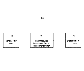
[30] FIG. 1 depicts a system 100 for reducing air ingress during a
pharmaceutical
formulation dosing process according to some embodiments. As shown in FIG. 1,
system 100
may include a density flow meter 102, pharmaceutical formulation density
assessment system
104, and at least one displacement pump 106. Each of these components may be
communicatively coupled with one another such that they may send and receive
electronic
information via network communication amongst one another. As shown in the
example of
FIG. 1, assessment system 104 may be communicatively coupled to both density
flow meter 102
and to at least one displacement pump 106. In addition, the density flow meter
can be fluidly
connected to the storage vessel. As such, when the pharmaceutical formulation
is drawn out of
the storage vessel, it can flow through the density flow meter where its
density can be measured.
In some embodiments, the density flow meter can be part of the recirculation
system as shown in
FIG. 2. For example, the density flow meter can be fluidly connected between
the storage vessel
and the recirculation pump.
[31] In some embodiments, density flow meter 102 can be used to provide a
consistent
and scientific end point to dosing and to prevent air ingress into the final
dosage forms. In some
embodiments, the density flow meter can measure the density of a fluid by way
of measuring the
Coriolis Effect. In some embodiments, the density flow meter is a Coriolis
single tube mass
flow meter. As such, when the pharmaceutical formulation is drawn out of the
storage vessel,
the density of the formulation can be measured by an evaluation of the
frequency of vibration
and temperature of the formulation. In some embodiments, the density flow
meter is a density
flow meter manufactured by Khrone In some embodiments, the density flow meter
measures
density in kg/m'. In some embodiments, the density flow meter can
measure/monitor mass flow
and density of the phaimaceutical formulation.
[32] In some embodiments, the pharmaceutical foimulation can be drawn out of
the
storage vessel by at least one displacement pump. In some embodiments, the
pharmaceutical
formulation can be drawn out of the recirculation system by at least one
displacement pump
labeled as dosing pump in FIG. 2. In some embodiments, the pharmaceutical
formulation can be
drawn out of the storage vessel by a plurality of displacement pumps. In some
embodiments,
the pharmaceutical formulation can be drawn out of the recirculation system by
a plurality of
displacement pumps. In some embodiments, the at least one displacement pump
can be fluidly
connected to the storage vessel, the density flow meter, the recirculation
system, the at least one
CA 03147021 2022-01-11
WO 2021/018978 PCT/EP2020/071428
manifold, and/or the preformed blister packs/molds. The at least one
displacement pump can be
responsible for displacing the pharmaceutical formulation from the storage
vessel to the
preformed blister packs/molds. For example, the at least one displacement pump
can displace
the pharmaceutical formulation that is circulating in the recirculation system
from the
recirculation system to the preformed blister packs/molds. As shown in FIG. 2,
the at least one
displacement pump can displace the pharmaceutical formulation that is
traveling through the at
least one manifold of the recirculation system and cause the pharmaceutical
formulation to flow
through the dosing lines and out the dosing nozzle(s) into the preformed
blister/molds. As such,
the pharmaceutical formulation may transport though various tubes (i.e.,
dosing lines/tubes), the
density flow meter, the recirculation pump, manifold(s), and the at least one
displacement pump
itself prior to being deposited in the preformed molds. As explained above,
the manifold(s) can
be used as a branching device for the pharmaceutical formulation to be split
into several
different dosing tubes for deposition into the individual preformed blister
packs/molds.
[33] In some embodiments, the at least one displacement pump displaces the
pharmaceutical formulation from the recirculation system and into the
preformed blister
packs/molds. In some embodiments, the at least one displacement pump displaces
the
pharmaceutical formulation from the manifold(s) of the recirculation system
and into the
preformed blister packs/molds. In some embodiments, the at least one
displacement pump
displaces the pharmaceutical formulation from the storage vessel through the
density flow meter.
In some embodiments, the at least displacement pump can draw the
pharmaceutical formulation
from the storage vessel, through a density flow meter, and into preformed
blister packs/molds.
In some embodiments, the density flow meter is fluidly connected between the
storage vessel
and the at least one displacement pump. In some embodiments, the density flow
meter is fluidly
connected between the storage vessel and the manifold(s). In some embodiments,
the at least
one displacement pump can draw the pharmaceutical formulation from the
recirculation system,
through the at least one displacement pump (and dosing tubes/lines before and
after the at least
one displacement pump), and into preformed blister packs/molds (by way of the
dosing
nozzle(s)). In some embodiments, the at least one displacement pump can draw
the
pharmaceutical formulation from the manifold(s) of the recirculation system,
through the at least
one displacement pump (and dosing tubes/lines before and after the at least
one displacement
pump), and into preformed blister packs/molds (by way of the dosing
nozzle(s)).
11
CA 03147021 2022-01-11
WO 2021/018978 PCT/EP2020/071428
[34] In some embodiments, phamiaceutical formulation density assessment system
104 can be any device or system comprising one or more computer processors
configured to
receive density data for the pharmaceutical formulation, assess and/or process
the received
density data, and to generate and transmit one or more output signals in
accordance with the
results of the density assessment. In some embodiments, assessment system 104
may be
provided, in whole or in part, as all or part of a desktop computing device,
laptop, tablet, mobile
electronic device, dedicated density processing device, computing module
processor, server,
cloud computing system, distributed computing system, or the like. In some
embodiments,
pharmaceutical formulation density assessment system 104 may be provided
locally with respect
to displacement pump(s) 106 and/or density flow meter 104 (e.g., in the room
where dosing
occurs), while in some embodiments density assessment system 104 may be
provided remotely
from displacement pump(s) 106 and/or density flow meter 104 (e.g., outside the
room where
dosing occurs, at a remote server location, etc).
[35] In some embodiments, assessment system 104 may be configured to receive
density data from density flow meter 102 and to process the density data to
determine whether
the density of the pharmaceutical formulation is at or below a predetermined
threshold in order
to stop the dosing process. In some embodiments, the predetermined density
threshold for a
given pharmaceutical formulation can be input into the assessment system by an
operator. For
example, for a given pharmaceutical formulation, the acceptable densities for
the formulation
can be determined prior to the dosing process by studies performed prior to
commercial dosing.
These studies include review of data obtained throughout the dosing process to
decipher the
exact point at which density drops in relation to progress of dosing. This
data is then used to set
a limit whereby the density flow meter is programmed to cease dosing
operations if the density
drops below this limit. The operator can then input the density threshold into
the assessment
system prior to starting the dosing process. In some embodiments, the end
point (i.e., the
predetermined threshold density) is set during development studies and can
typically be 50
kg/m3 lower than the level recorded during the dosing process.
[36] In some embodiments, assessment system 104 may be configured to send one
or
more instruction or control signals to displacement pump(s) 106 configured to
cause
displacement pump(s) to alter an activation state of the pump(s) (e.g., to
turn from off to on, or
turn from on to off); in some embodiments, as discussed in detail herein, the
instruction or
12
CA 03147021 2022-01-11
WO 2021/018978 PCT/EP2020/071428
control signal may be sent by assessment system 104 in accordance with the
detemiined density
based on analysis of the density data received from density flow meter 102.
For example, in
some embodiments, if the density of the pharmaceutical formulation falls below
a predetermined
threshold, then a signal may be sent directing displacement pump(s) 106 to be
turned off,
thereby stopping the dosing process. In some embodiments, when displacement
pump(s) 106 is
turned off, no more pharmaceutical formulation will be drawn from the
recirculation system. In
some embodiments, when the density flow meter detects a change in the mass
flow of the matrix
(i.e., air ingress or particulate matter), an alarm can be triggered and the
dosing procedure is
automatically stopped.
[37] As described herein, displacement pump(s) 106 may be configured to be
turned
off (i.e., stop displacing the pharmaceutical formulation from the
recirculation system or storage
vessel to the preformed molds) when the density of the pharmaceutical
formulation measured by
the density flow meter falls below a predetermined threshold. As discussed
above, in some
embodiments, displacement pump(s) 106 may be configured to have an activation
state modified
in accordance with an instruction signal or control signal received from
pharmaceutical
formulation density assessment system 104 by any wired or wireless electronic
communication
medium, including by any suitable network communication protocol.
[38] Accordingly, when air begins to be drawn into the recirculation system
for the
storage vessel (i.e., when the storage vessel empties), the density of the
pharmaceutical
formulation can start to decrease with the addition of air to the formulation.
This change can
cause the density flow meter to signal to cease dosing. As such, the operator
no longer is
required to visually monitor the pharmaceutical formulation in the storage
vessel. Instead, as the
formulation's density reaches a predetermined threshold, the dosing process
can stop. End of
batch does weights can be taken and the batch can be automatically stopped.
Thus, air ingress
into the dosage forms can be prevented by this automatic ceasing of the dosing
process when the
density of the pharmaceutical formulation falls below a certain level.
[39] After dosing, the dosed pharmaceutical formulations can be frozen in the
preformed blister packs/molds. The dosed fomiulations in the preformed blister
packs/molds
can be frozen by any means known in the art. For example, the formulations can
be passed
through a cryogenic chamber (e.g., liquid nitrogen tunnel). In some
embodiments, the frozen
units in the preformed blister packs/molds can be collected and placed in a
freezer prior to freeze
13
CA 03147021 2022-01-11
WO 2021/018978 PCT/EP2020/071428
drying. The frozen units can be freeze-dried to form the dosage foims. During
the freeze-
drying process, the water is sublimated from the frozen units. In some
embodiments, the frozen
units can be loaded onto the shelves of a freeze-drier. Once the frozen units
are in the freeze-
drier, the freeze-drying cycle can be initiated. In some embodiments, a vacuum
can be pulled
and the shelf temperature raised once the freeze-drying cycle is initiated.
The freeze-drier can
operate at low pressure (i.e., vacuum).
[40] The freeze-dried dosage forms can be removed from the freeze-drier and
inspected for any defects. On completion of the freeze drying cycle, the
dosage forms can be
sealed (e.g., lidding foil applied to blister). The dosage forms of the
present disclosure are
dissolving dosage forms and accordingly have the distinct advantage of a
faster disintegrating
time.
[41] FIG. 3 illustrates a computer, in accordance with some embodiments.
Computer
300 can be a component of a system for dosing a pharmaceutical formulation, as
described
above and with respect to FIGS. 1 and 2. In some embodiments, computer 300 may
be
configured to execute a method for dosing a phaimaceutical formulation, as
described above.
[42] Computer 300 can be a host computer connected to a network. Computer 300
can be a client computer or a server. As shown in FIG. 3, computer 300 can be
any suitable type
of microprocessor-based device, such as a personal computer; workstation;
server; or handheld
computer device, such as a phone or tablet. The computer can include, for
example, one or more
of processor 310, input device 320, output device 330, storage 340, and
communication device
360.
[43] Input device 320 can be any suitable device that provides input, such as
a touch
screen or monitor, keyboard, mouse, or voice-recognition device. Output device
330 can be any
suitable device that provides output, such as a touch screen, monitor,
printer, disk drive, or
speaker.
[44] Storage 340 can be any suitable device that provides storage, such as
an
electrical, magnetic, or optical memory, including a RAM, cache, hard drive,
CD-ROM drive,
tape drive, or removable storage disk. Communication device 360 can include
any suitable
device capable of transmitting and receiving signals over a network, such as a
network interface
chip or card. The components of the computer can be connected in any suitable
manner, such as
14
CA 03147021 2022-01-11
WO 2021/018978 PCT/EP2020/071428
via a physical bus or wirelessly. Storage 340 can be a non-transitory computer-
readable storage
medium comprising one or more programs, which, when executed by one or more
processors,
such as processor 310, cause the one or more processors to execute methods
described herein,
such as all or part of the methods described above with respect to dosing a
pharmaceutical
formulation.
[45] Software 350, which can be stored in storage 340 and executed by
processor 310,
can include, for example, the programming that embodies the functionality of
the present
disclosure (e.g., as embodied in the systems, computers, servers, and/or
devices as described
above). In some embodiments, software 350 can be implemented and executed on a
combination of servers such as application servers and database servers.
[46] Software 350 can also be stored and/or transported within any computer-
readable
storage medium for use by or in connection with an instruction execution
system, apparatus, or
device, such as those described above, that can fetch and execute instructions
associated with the
software from the instruction execution system, apparatus, or device. In the
context of this
disclosure, a computer-readable storage medium can be any medium, such as
storage 340, that
can contain or store programming for us by or in connection with an
instruction execution
system, apparatus, or device.
[47] Software 350 can also be propagated within any transport medium for use
by or
in connection with an instruction execution system, apparatus, or device, such
as those described
above, that can fetch and execute instructions associated with the software
from the instruction
execution system, apparatus, or device. In the context of this disclosure, a
transport medium can
be any medium that can communicate, propagate, or transport programming for
use by or in
connection with an instruction execution system, apparatus, or device. The
transport-readable
medium can include, but is not limited to, an electronic, magnetic, optical,
electromagnetic, or
infrared wired or wireless propagation medium.
[48] Computer 300 may be connected to a network, which can be any suitable
type of
interconnected communication system. The network can implement any suitable
communications protocol and can be secured by any suitable security protocol.
The network can
comprise network links of any suitable arrangement that can implement the
transmission and
CA 03147021 2022-01-11
WO 2021/018978 PCT/EP2020/071428
reception of network signals, such as wireless network connections, Ti or T3
lines, cable
networks, DSL, or telephone lines.
[49] Computer 300 can implement any operating system suitable for operating on
the
network. Software 350 can be written in any suitable programming language,
such as C, C++,
Java, or Python. In various embodiments, application software embodying the
functionality of
the present disclosure can be deployed in different configurations, such as in
a client/server
arrangement or through a Web browser as a Web-based application or Web
service, for
example.
[50] The preceding description sets forth exemplary methods, parameters and
the like.
It should be recognized, however, that such description is not intended as a
limitation on the
scope of the present disclosure but is instead provided as a description of
exemplary
embodiments. The illustrative embodiments described above are not meant to be
exhaustive or
to limit the disclosure to the precise forms disclosed. Many modifications and
variations are
possible in view of the above teachings. The embodiments were chosen and
described to best
explain the principles of the disclosed techniques and their practical
applications. Others skilled
in the art are thereby enabled to best utilize the techniques, and various
embodiments with
various modifications as are suited to the particular use contemplated.
[51] Although the disclosure and examples have been thoroughly described with
reference to the accompanying figures, it is to be noted that various changes
and modifications
will become apparent to those skilled in the art. Such changes and
modifications are to be
understood as being included within the scope of the disclosure and examples
as defined by the
claims. In the preceding description of the disclosure and embodiments,
reference is made to the
accompanying drawings, in which are shown, by way of illustration, specific
embodiments that
can be practiced. It is to be understood that other embodiments and examples
can be practiced,
and changes can be made without departing from the scope of the present
disclosure.
[52] Although the preceding description uses teiins first, second, etc. to
describe
various elements, these elements should not be limited by the terms. These
terms are only used
to distinguish one element from another.
[53] Also, it is also to be understood that the singular forms "a," "an,"
and "the" used
in the preceding description are intended to include the plural forms as well
unless the context
16
CA 03147021 2022-01-11
WO 2021/018978 PCT/EP2020/071428
indicates otherwise. It is also to be understood that the term "and/or" as
used herein refers to and
encompasses any and all possible combinations of one or more of the associated
listed items. It
is further to be understood that the watts "includes, "including,"
"comprises," and/or
"comprising," when used herein, specify the presence of stated features,
integers, steps,
operations, elements, components, and/or units but do not preclude the
presence or addition of
one or more other features, integers, steps, operations, elements, components,
units, and/or
groups thereof
[54] The term "if" may be construed to mean "when" or "upon" or "in response
to
determining" or "in response to detecting," depending on the context
[55] Although the disclosure and examples have been fully described with
reference to
the accompanying figures, it is to be noted that various changes and
modifications will become
apparent to those skilled in the art. Such changes and modifications are to be
understood as
being included within the scope of the disclosure and examples as defined by
the claims.
17
CA 03147021 2022-01-11
WO 2021/018978 PCT/EP2020/071428
[56]
The following numbered clauses set out further embodiments of the invention:
I. A system for dosing a pharmaceutical formulation comprising:
a vessel for storing a pharmaceutical formulation;
a recirculation system comprising a density flow meter fluidly connected to
the vessel
and a recirculation pump fluidly connected to the density flow meter and the
vessel, wherein the
recirculation pump is configured to displace the pharmaceutical formulation
from the vessel
through the density flow meter and the density flow meter is configured to
measure a density of
the pharmaceutical formulation;
at least one pump fluidly connected to the recirculation system, wherein the
at least one
pump is configured to displace the pharmaceutical formulation from the
recirculation system
and into preformed molds,
wherein the at least one pump is configured to stop displacing the
pharmaceutical
formulation from the recirculation system when the density of the
pharmaceutical formulation
measured by the density flow meter is below a predetermined threshold.
2. The system of clause 1, further comprising a computer, wherein the
computer, the density
flow meter, and the at least one pump are communicatively coupled with one
another.
3. The system of clause 2, wherein the density flow meter is configured to
send data
comprising the density of the pharmaceutical formulation to the computer.
4. The system of clause 3, wherein the computer is configured to send one or
more instruction
or control signals to the at least one pump to alter an activation state of
the pump.
5. The system of clause 4, wherein the activation state comprises an on
configuration and an
off configuration.
6. The system of any of clauses 4-5, wherein the one or more instruction or
control signals sent
from the computer to the at least one pump comprises a signal to turn the at
least one pump
off when the data comprising the density of the pharmaceutical formulation is
below a
predetermined threshold.
18
CA 03147021 2022-01-11
WO 2021/018978 PCT/EP2020/071428
7. The system of any of clauses 2-6, wherein the computer, the density flow
meter, and the at
least one pump are wirelessly communicatively coupled with one another.
8. The system of any of clauses 1-7, wherein the recirculation pump is
configured to displace
the pharmaceutical formulation from the vessel through the density flow meter,
through the
recirculation pump, and back into the vessel.
9. The system of any of clauses 1-8, the recirculation system further
comprises a manifold.
10. The system of clause 9, wherein the recirculation pump is configured to
displace the
pharmaceutical formulation from the vessel through the density flow meter,
through the
recirculation pump, through the manifold, and back into the vessel.
11. The system of any of clauses 9-10, wherein the at least one pump is
configured to displace
the pharmaceutical formulation from the manifold and into preformed molds.
12 The system of any of clauses 1-11, wherein the vessel comprises a stirrer.
13. The system of any of clauses 1-12, wherein the pharmaceutical formulation
comprises at
least one of sodium lauryl sulfate and sodium docusate.
14. A method for dosing a phaimaceutical formulation, the method comprising:
storing a pharmaceutical formulation in a vessel;
displacing the pharmaceutical formulation from the vessel through a density
flow meter,
wherein the density flow meter is configured to measure a density of the
pharmaceutical
formulation;
dosing the pharmaceutical formulation into preformed molds;
stopping the dosing of the pharmaceutical formulation into preformed molds
when the
density of the pharmaceutical formulation measured by the density flow meter
is below a
predetermined threshold.
15. The method of clause 14, wherein the density flow meter is configured to
send data
comprising the density of the pharmaceutical formulation to a computer.
16. The method of clause 15, wherein the computer is configured to send one or
more
instruction or controls signals to stop the dosing of the pharmaceutical
formulation when the
19
CA 03147021 2022-01-11
WO 2021/018978 PCT/EP2020/071428
data comprising the density of the phamiaceutical formulation is below a
predetermined
threshold.
17. The method of clause 16, wherein the computer sends the one or more
instruction or control
signals to stop dosing of the pharmaceutical formulation to at least one pump.
18. The method of clause 17, wherein the computer, the density flow meter, and
the at least one
pump are wirelessly communicatively coupled with one another.
19. The method of any of clauses 14-18, further comprising recirculating a
portion of the
pharmaceutical formulation to the vessel after passing through the density
flow meter.
20. The method of any of clauses 14-19, wherein the pharmaceutical formulation
comprises at
least one of sodium lauryl sulfate and sodium docusate.