Note: Descriptions are shown in the official language in which they were submitted.
WO 2021/055193
PCT/U52020/049845
PACKAGING MATERIAL GRADING AND/OR FACTORY PROFILES
Field of the Invention
[0001] The invention generally relates to wrapping loads with packaging
material through relative rotation of loads and a packaging material
dispenser, and in
particular, to a control system therefor.
Background of the Invention
[0002] Various packaging techniques have been used to build a load of unit
products and subsequently wrap them for transportation, storage, containment
and
stabilization, protection and waterproofing. One system uses wrapping machines
to
stretch, dispense, and wrap packaging material around a load. The packaging
material
may be pre-stretched before it is applied to the load_ Wrapping can be
performed as an
inline, automated packaging technique that dispenses and wraps packaging
material in
a stretch condition around a load on a pallet to cover and contain the load.
Stretch
wrapping, whether accomplished by a turntable, rotating arm, vertical rotating
ring, or
horizontal rotating ring, typically covers the four vertical sides of the load
with a
stretchable packaging material such as polyethylene packaging material. In
each of
these arrangements, relative rotation is provided between the load and the
packaging
material dispenser to wrap packaging material about the sides of the load.
[0003] A primary metric used in the shipping industry for gauging overall
wrapping effectiveness is containment force, which is generally the cumulative
force
exerted on the load by the packaging material wrapped around the load.
Containment
force depends on a number of factors, including the number of layers of
packaging
material, the thickness, strength and other properties of the packaging
material, the
amount of pm-stretch applied to the packaging material, and the wrap force
applied to
the load while wrapping the load. The wrap force, however, is a force that
fluctuates as
packaging material is dispensed to the load due primarily to the irregular
geometry of
the load.
CA 03147093 2022-2-4
WO 2021/055193
PCT/US2020/049845
[00041 In particular, wrappers have historically
suffered from packaging
material breaks and limitations on the amount of wrap force applied to the
load (as
determined in part by the amount of pm-stretch used) due to erratic speed
changes
required to wrap loads. Were all loads perfectly cylindrical in shape and
centered
precisely at the center of rotation for the relative rotation, the rate at
which packaging
material would need to be dispensed would be constant throughout the rotation.
Typical loads, however, are generally box-shaped, and have a square or
rectangular
cross-section in the plane of rotation, such that even in the case of square
loads, the
rate at which packaging material is dispensed varies throughout the rotation.
In some
instances, loosely wrapped loads result due to the supply of excess packaging
material
during portions of the wrapping cycle where the demand rate for packaging
material by
the load is exceeded by the rate at which the packaging material is supplied
by the
packaging material dispenser. In other instances, when the demand rate for
packaging
material by the load is greater than the supply rate of the packaging material
by the
packaging material dispenser, breakage of the packaging material may occur.
[00051 When wrapping a typical rectangular load, the demand for packaging
material typically decreases as the packaging material approaches contact with
a
corner of the load and increases after contact with the comer of the load. In
horizontal
rotating rings, when wrapping a tall, narrow load or a short load, the
variation in the
demand rate is typically even greater than in a typical rectangular load. In
vertical
rotating rings, high speed rotating arms, and turntable apparatuses, the
variation is
caused by a difference between the length and the width of the load, while in
a
horizontal rotating ring apparatus, the variation is caused by a difference
between the
height of the load (distance above the conveyor) and the width of the load.
Variations in
demand may make it difficult to properly wrap the load, and the problem with
variations
may be exacerbated when wrapping a load having one or more dimensions that may
differ from one or more corresponding dimensions of a preceding load. The
problem
may also be exacerbated when wrapping a load having one or more dimensions
that
vary at one or more locations of the load itself. Furthermore, whenever a load
is not
centered precisely at the center of rotation of the relative rotation, the
variation in the
demand rate is also typically greater, as the corners and sides of even a
perfectly
symmetric load will be different distances away from the packaging material
dispenser
as they rotate past the dispenser.
2
CA 03147093 2022-2-4
WO 2021/055193
PCT/US2020/049845
[00061 The amount of force, or pull, that the packaging material exhibits on
the load determines in part how tightly and securely the load is wrapped.
Conventionally, this wrap force is controlled by controlling the feed or
supply rate of the
packaging material dispensed by the packaging material dispenser. For example,
the
wrap force of many conventional stretch wrapping machines is controlled by
attempting
to alter the supply of packaging material such that a relatively constant
packaging
material wrap force is maintained. With powered pre-stretching devices,
changes in the
force or tension of the dispensed packaging material are monitored, e.g., by
using
feedback mechanisms typically linked to spring loaded dancer bars, electronic
load
cells, or torque control devices. The changing force or tension of the
packaging material
caused by rotating a rectangular shaped load is transmitted back through the
packaging
material to some type of sensing device, which attempts to vary the speed of
the motor
driven dispenser to minimize the change. The passage of the corner causes the
force
or tension of the packaging material to increase, and the increase is
typically
transmitted back to an electronic load cell, spring-loaded dancer
interconnected with a
sensor, or to a torque control device. As the corner approaches, the force or
tension of
the packaging material decreases, and the reduction is transmitted back to
some
device that in turn reduces the packaging material supply to attempt to
maintain a
relatively constant wrap force or tension.
(00071 With the over faster wrapping rates demanded by the industry,
however, rotation speeds have increased significantly to a point where the
concept of
sensing changes in force and altering supply speed in response often loses
effectiveness. The delay of response has been observed to begin to move out of
phase
with rotation at approximately 20 RPM. Given that a packaging dispenser is
required to
shift between accelerating and decelerating eight times per revolution in
order to
accommodate the four corners of the load, at 20 RPM the shift between
acceleration
and deceleration occurs at a rate of more than every once every half of a
second.
Given also that the rotating mass of a packaging material roll and rollers in
a packaging
material dispenser may be 100 pounds or more, maintaining an ideal dispense
rate
throughout the relative rotation can be a challenge.
[00081 Also significant is the need in many applications to minimize
acceleration and deceleration times for faster cycles. Initial acceleration
must pull
3
CA 03147093 2022-2-4
WO 2021/055193
PCT/US2020/049845
against clamped packaging material, which typically cannot stand a high force,
and
especially the high force of rapid acceleration, which typically cannot be
maintained by
the feedback mechanisms described above. As a result of these challenges, the
use of
high speed wrapping has often been limited to relatively lower wrap forces and
pre-
stretch levels where the loss of control at high speeds does not produce
undesirable
packaging material breaks.
[0009] In addition, due to environmental, cost
and weight concerns, an
ongoing desire exists to reduce the amount of packaging material used to wrap
loads,
typically through the use of thinner, and thus relatively weaker packaging
materials
and/or through the application of fewer layers of packaging material. As such,
maintaining adequate containment forces in the presence of such concerns,
particularly
in high speed applications, can be a challenge.
[0010] Another difficulty associated with conventional wrapping machines is
based on the difficulty in selecting appropriate control parameters to ensure
that an
adequate containment force is applied to a load. In many wrapping machines,
the
width of the packaging material is significantly less than the height of the
load, and a lift
mechanism is used to move a roll carriage in a direction generally parallel to
the axis of
rotation of the wrapping machine as the load is being wrapped, which results
in the
packaging material being wrapped in a generally spiral manner around the load.
Conventionally, an operator is able to control a number of wraps around the
bottom of
the load, a number of wraps around the top of the load, and a speed of the
roll carriage
as it traverses between the top and bottom of the load to manage the amount of
overlap
between successive wraps of the packaging material. In some instances, control
parameters may also be provided to control an amount of overlap (e.g., in
inches)
between successive wraps of packaging material.
[0011] The control of the roll carriage in this manner, when coupled with the
control of the wrap force applied during wrapping, may result in some loads
that are
wrapped with insufficient containment force throughout, or that consume
excessive
packaging material (which also has the side effect of increasing the amount of
time
required to wrap each load). In part, this may be due in some instances to an
uneven
distribution of packaging material, as it has been found that the overall
integrity of a
wrapped load is based on the integrity of the weakest portion of the wrapped
load.
4
CA 03147093 2022-2-4
WO 2021/055193
PCT/US2020/049845
Thus, if the packaging material is wrapped in an uneven fashion around a load
such
that certain portions of the load have fewer layers of overlapping packaging
material
and/or packaging material applied with a lower wrap force, the wrapped load
may lack
the desired integrity regardless of how well it is wrapped in other portions.
[00121 Ensuring even and consistent containment force throughout a load,
however, has been found to be challenging, particularly for less experienced
operators.
Traditional control parameters such as wrap force, roll carriage speed, etc.
frequently
result in significant variances in number of packaging material layers and
containment
forces applied to loads from top to bottom. Furthermore, many operators lack
sufficient
knowledge of packaging material characteristics and comparative performance
between different brands, thicknesses, materials, etc., so the use of
different packaging
materials often further complicates the ability to provide even and consistent
wrapped
loads.
[00131 As an example, many operators will react to excessive film breaks by
simply reducing wrap force, which leads to inadvertent lowering of cumulative
containment forces below desired levels. The effects of insufficient
containment forces,
however, may not be discovered until much later, when wrapped loads are loaded
into
trucks, ships, airplanes or trains and subjected to typical transit forces and
conditions.
Failures of wrapped loads may lead to damaged goods during transit, loading
and/or
unloading, increasing costs as well as inconveniencing customers,
manufacturers and
shippers alike.
[00141 Another approach may be to simply lower the speed of a roll carriage
and increase the amount of packaging material applied in response to loads
being
found to lack adequate containment force; however, such an approach may
consume
an excessive amount of packaging material, thereby increasing costs and
decreasing
the throughput of a wrapping machine.
[00151 Therefore, a significant need continues to exist in the art for an
improved manner of reliably and efficiently controlling the containment force
applied to
a wrapped load.
CA 03147093 2022-2-4
WO 2021/055193 PCT/US2020/049845
Summary of the Invention
[00161 The invention addresses these and other problems associated with the
art by providing in one aspect a method, apparatus and program product that
utilize one
or both of packaging material grading and factory profiles to facilitate
wrapping.
[00171 Therefore, consistent with one aspect of the invention, a method of
controlling a load wrapping apparatus of the type configured to wrap a load on
a load
support with packaging material dispensed from a packaging material dispenser
through relative rotation between the packaging material dispenser and the
load
support may include receiving first input data associated with a packaging
material
thickness, receiving second input data associated with a packaging material
grade,
determining a wrap force parameter for use in wrapping the load using the
first and
second input data, and controlling a dispense rate of the packaging material
dispenser
during the relative rotation based on the determined wrap force parameter.
[00181 In some embodiments, the grade is selected from among a plurality of
predetermined grades. Also, in some embodiments, the grade is selected from
among
an ultra grade, a premium grade, a standard grade and a low bid grade. In
addition,
some embodiments may further include maintaining a mapping of load containment
forces to corresponding wrap forces and numbers of layers of packaging
material and
receiving third input data associated with a load containment force
requirement to be
used when wrapping the load with packaging material, where determining the
wrap
force parameter includes accessing the mapping based upon the third input data
to
determine a corresponding wrap force parameter and a corresponding layer
parameter
for the load containment force requirement, and controlling the dispense rate
is further
based on the determined corresponding layer parameter.
[00191 Further, in some embodiments, the layer parameter specifies a
minimum number of layers of packaging material to apply throughout a
contiguous
region of the load. In some embodiments, the layer parameter specifies an
amount of
overlap between successive revolutions, a carriage or elevator speed, a number
of up
and/or down passes of a carriage or elevator, or a number of relative
revolutions. In
addition, in some embodiments, the mapping maps the corresponding wrap force
and
layer parameters for the load containment force requirement further based on
the
packaging material thickness and the packaging material grade. In some
6
CA 03147093 2022-2-4
WO 2021/055193
PCT/US2020/049845
embodiments, determining the wrap force parameter is further based upon an
incremental containment force, the method further including determining the
incremental containment force from an incremental containment force function
that
varies across a range of packaging material thicknesses and a range of grades
using
the first and second input data.
[130201 Some embodiments may also include determining the wrap force
parameter based on a factory profile. In addition, some embodiments may also
include
receiving third input data selecting the factory profile from a set of
predefined factory
profiles, each profile in the set of predefined factory profiles including one
or more wrap
settings and optionally one or more special wrapping features. Moreover, in
some
embodiments, the set of predefined factory profiles includes a regular light
profile, a
regular heavy profile, an irregular light profile, an irregular heavy profile,
a sharp edge
profile, an incomplete top layer profile, a soft top profile, a prewrapped
double load
profile, a short normal profile and/or a short one layer inboard profile.
[00211 Consistent with another aspect of the invention, a method of
controlling a load wrapping apparatus of the type configured to wrap a load on
a load
support with packaging material dispensed from a packaging material dispenser
through relative rotation between the packaging material dispenser and the
load
support may include receiving first input data selecting from among a set of
predefined
factory profiles, each profile in the set of predefined factory profiles
including one or
more wrap settings and optionally one or more special wrapping features, and
controlling a dispense rate of the packaging material dispenser during the
relative
rotation based on the first input data and optionally performing one or more
special
wrapping features based upon the first input data.
(00221 In some embodiments, the set of predefined factory profiles includes a
regular light profile for light loads without sharp edges and requiring no
special features,
and the regular light profile specifies a moderate wrap force parameter.
Moreover, in
some embodiments, the set of predefined factory profiles includes a regular
heavy
profile for heavier loads without sharp edges and requiring no special
features, and the
regular heavy profile specifies a high wrap force parameter. In some
embodiments, the
set of predefined factory profiles includes an irregular light profile for
light loads and/or
irregular loads with sharp edges and requiring no special features, and the
irregular
7
CA 03147093 2022-2-4
WO 2021/055193
PCT/US2020/049845
light profile specifies a low wrap force parameter. In addition, in some
embodiments,
the set of predefined factory profiles includes an irregular heavy profile for
heavier loads
with irregularities and/or with sharp edges and requiring no special features,
and the
irregular heavy profile specifies a moderate wrap force parameter.
[0023] In some embodiments, the set of predefined factory profiles includes a
sham edge profile for severely inboard loads and/or very sharp loads and
requiring no
special features, and the regular light profile specifies a low wrap force
parameter.
Moreover, in some embodiments, the set of predefined factory profiles includes
an
incomplete top layer profile for loads having incomplete top layers, and the
incomplete
top layer profile specifies a moderate wrap force parameter and a special
feature that
causes a rate of rotation to slow for a predetermined number of relative
revolutions to
allow an operator to hand rope around a top layer of the load. Also, in some
embodiments, the set of predefined factory profiles includes a soft top
profile for loads
having top layers that are soft and/or light, and the soft top profile
specifies a moderate
wrap force parameter and a special feature that reduces the wrap force
parameter at
the top of the load for one or more relative revolutions. In some embodiments,
the set
of predefined factory profiles includes a prewrapped double load profile for
loads having
two previously-wrapped and stacked loads, and the prewrapped double load
profile
specifies a special feature that raises a carriage to a center of a stack of
two loads,
pauses until a leading end of packaging material is attached, and wraps a
predetermined number of layers of packaging material around the center of the
stack.
In addition, in some embodiments, the set of predefined factory profiles
includes a short
normal profile for short loads, and the short normal profile specifies a
moderate wrap
force parameter and a special feature that wraps packaging material around a
bottom
of the load_ Also, in some embodiments, the set of predefined factory profiles
includes
a short one layer profile for short loads requiring roping, and the short one
layer profile
specifies a special feature that wraps at a slow rate for a predetermined
number of
relative revolutions to enable an operator to hand rope around the load.
[00241 Moreover, in some embodiments, the set of predefined factory profiles
includes a regular light profile, a regular heavy profile, an irregular light
profile, an
irregular heavy profile, a sharp edge profile, an incomplete top layer
profile, a soft top
8
CA 03147093 2022-2-4
WO 2021/055193
PCT/US2020/049845
profile, a prewrapped double load profile, a short normal profile and a short
one layer
inboard profile.
[00251 Some embodiments may also include a load wrapping apparatus
including a packaging material delivery system configured to convey a web of
packaging material from a packaging material roll to a body including a load
to apply a
controlled stretch to the packaging material prior to the packaging material
being
wrapped around the load and configured to perform any of the aforementioned
methods_ Some embodiments may also include an apparatus that includes a
processor
and program code configured upon execution by the processor to control a load
wrapping apparatus of the type configured to wrap a load on a load support
with
packaging material dispensed from a packaging material dispenser through
relative
rotation between the packaging material dispenser and the load support using
any of
the aforementioned methods. Some embodiments may further include a program
product that includes a non-transitory computer readable medium and program
code
stored on the non-transitory computer readable medium and configured to
control a
load wrapping apparatus of the type configured to wrap a load on a load
support with
packaging material dispensed from a packaging material dispenser through
relative
rotation between the packaging material dispenser and the load support, where
the
program code is configured to control the load wrapping apparatus by
perfomiing any of
the aforementioned methods.
[00261 These and other advantages and features, which characterize the
invention, are set forth in the claims annexed hereto and forming a further
part hereof.
However, for a better understanding of the invention, and of the advantages
and
objectives attained through its use, reference should be made to the Drawings,
and to
the accompanying descriptive matter, in which there is described exemplary
embodiments of the invention.
Brief Description of the Drawing's
[00271 FIGURE 'I shows a top view of a rotating arm-type wrapping
apparatus consistent with the invention.
[0028] FIGURE 2 is a schematic view of an exemplary control system for use
in the apparatus of Fig. 1.
9
CA 03147093 2022-2-4
WO 2021/055193
PCT/US2020/049845
[00291 FIGURE 3 shows a top view of a rotating ring-type wrapping apparatus
consistent with the invention.
[00301 FIGURE 4 shows a top view of a turntable-type wrapping apparatus
consistent with the invention.
[0031] FIGURE 5 is a perspective view of a turntable-type wrapping
apparatus consistent with the invention_
[0032] FIGURE 6 is a block diagram illustrating an example load containment
force-based control system consistent with the invention.
[0033] FIGURE 7 is a flowchart illustrating a sequence of steps in an example
routine for configuring a wrap profile in the control system of Fig, 6.
[0034] FIGURE 8 is a flowchart illustrating a sequence of steps in an example
routine for performing a wrapping operation in the control system of Fig. 6.
[00351 FIGURE 9 is a flowchart illustrating a sequence of steps in an example
routine for performing another wrapping operation in the control system of
Fig. 6, but
based upon operator input of a load containment force requirement.
[O0361 FIGURE 10 is a flowchart illustrating a sequence of steps in an
example routine for performing another wrapping operation in the control
system of Fig.
6, but based upon operator input of a number of layers of packaging material
to apply to
a load.
[0037] FIGURES 11-13 are block diagrams of example displays capable of
being displayed by the control system of Fig. 6 when interacting with an
operator.
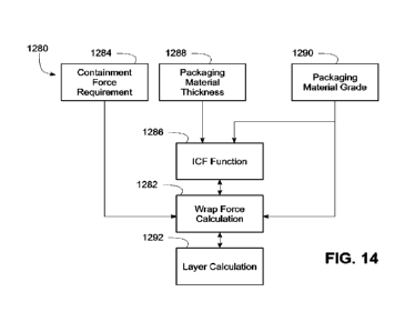
[0038] FIGURE 14 is a block diagram illustrating wrapping parameter
calculations based on packaging material grades.
[0039] FIGURE 15 is a flowchart illustrating an example sequence of
operations for grading a packaging material consistent with some embodiments
of the
invention.
CA 03147093 2022-2-4
WO 2021/055193
PCT/US2020/049845
Detailed Description
[00401 Embodiments consistent with the invention utilize various techniques
to facilitate control of a wrapping apparatus based at least in part on the
grading of a
packaging material used during wrapping and/or the use of a factory profile.
Prior to a
discussion of the aforementioned concepts, however, a bdef discussion of
various
types of wrapping apparatus within which the various techniques disclosed
herein may
be implemented is provided.
(0041) In addition, the disclosures of each of
U.S. Pat. No. 4,418,510, entitled
"STRETCH WRAPPING APPARATUS AND PROCESS," and filed Apr, 17, 1981; U.S.
Pat. No. 4,953,336, entitled "HIGH TENSILE WRAPPING APPARATUS," and filed Aug.
17.1989; U.S. Pat. No. 4,503,658, entitled "FEEDBACK CONTROLLED STRETCH
WRAPPING APPARATUS AND PROCESS," and filed Mar. 28, 1983; U.S. Pat_ No.
4,676,048, entitled "SUPPLY CONTROL ROTATING STRETCH WRAPPING
APPARATUS AND PROCESS," and filed May 20, 1986; U.S. Pat. No. 4,514,955,
entitled "FEEDBACK CONTROLLED STRETCH WRAPPING APPARATUS AND
PROCESS," and filed Apr. 6, 1981; U.S. Pat. No. 6,748,718, entitled "METHOD
AND
APPARATUS FOR WRAPPING A LOAD," and filed Oct. 31, 2002; U.S. Pat. No.
7,707,801, entitled "METHOD AND APPARATUS FOR DISPENSING A
PREDETERMINED FIXED AMOUNT OF PRE-STRETCHED FILM RELATIVE TO
LOAD GIRTH: filed Apr. 6, 2006; US. Pat. No. 8,037,660, entitled "METHOD AND
APPARATUS FOR SECURING A LOAD TO A PALLET WITH A ROPED FILM WEB:
and filed Feb. 23, 2007; U.S. Patent Application Publication No. 2007/0204565,
entitled
"METHOD AND APPARATUS FOR METERED PRE-STRETCH FILM DELIVERY," and
filed Sep. 6, 2007; U.S, Pat. No. 7,779,607, entitled WRAPPING APPARATUS
INCLUDING METERED PRE-STRETCH FILM DELIVERY ASSEMBLY AND METHOD
OF USING," and filed Feb. 23, 2007; U.S. Patent Application Publication No.
2009/0178374, entitled "ELECTRONIC CONTROL OF METERED FILM DISPENSING
IN A WRAPPING APPARATUS," and filed Jan. 7, 2009; U.S. Patent Application
Publication No. 2011/0131927, entitled "DEMAND BASED WRAPPING," and filed Nov.
6, 2010; U. S. Patent Application Publication No. 2012/0102886. entitled
"METHODS
AND APPARATUS FOR EVALUATING PACKAGING MATERIALS AND
DETERMINING WRAP SETTINGS FOR WRAPPING MACHINES,' and filed Oct_ 28,
2011; U. S. Patent Application Publication No. 2012/0102887, entitled "MACHINE
11
CA 03147093 2022-2-4
WO 2021/055193
PCT/US2020/049845
GENERATED WRAP DATA: and filed Oct. 28, 2011; U.S. provisional patent
application SiN 61/718,429, entitled "ROTATION ANGLE-BASED WRAPPING," and
filed Oct. 25, 2012; U.S. provisional patent application &IN 61/718433,
entitled
"EFFECTIVE CIRCUMFERENCE-BASED WRAPPING," and filed Oct. 25, 2012; U.S.
patent application &NI 14/052,929, entitled 'ROTATION ANGLE-BASED WRAPPING,"
and filed Oct. 25, 2013; U.S. patent application SiN 141052,930, entitled
"EFFECTIVE
CIRCUMFERENCE-BASED WRAPPING?' and filed Oct. 25, 2013; US. patent
application S/N 14/052,931, entitled 'CORNER GEOMETRY-BASED WRAPPING," and
filed Oct. 25, 2013; U.S. provisional patent application SIN 61/764,107,
entitled
"CONTAINMENT FORCE-BASED WRAPPING," and filed February 13, 2013; U.S.
Patent Application Publication No. 2014/0223,863, entitled "PACKAGING MATERIAL
PROFILING FOR CONTAINMENT FORCE-BASED WRAPPING,' and filed February
13,2014; U.S. Patent Application Publication No. 2014/0223,864, entitled
"CONTAINMENT FORCE-BASED WRAPPING," and filed February 13, 2014; U.S.
Patent Application Publication No. 2016/0096646, entitled "LOAD STABILITY-
BASED
WRAPPING," and filed October 7, 2015; and U.S. provisional patent application
SIN
62/821,146, entitled 'PACKAGING MATERIAL EVALUATION AND TEST APPARATUS
THEREFOR,' and filed March 20, 2019, are incorporated herein by reference in
their
entirety.
Wrapping Apparatus Configurations
[00421 Fig_ 1, for example, illustrates a rotating arm-type wrapping apparatus
100, which includes a roll carriage 102 mounted on a rotating arm 104. Roll
carriage
102 may include a packaging material dispenser 106. Packaging material
dispenser
106 may be configured to dispense packaging material 108 as rotating arm 104
rotates
relative to a load 110 to be wrapped. In an example embodiment, packaging
material
dispenser 106 may be configured to dispense stretch wrap packaging material.
As used
herein, stretch wrap packaging material is defined as material having a high
yield
coefficient to allow the material a large amount of stretch during wrapping_
However, it
is possible that the apparatuses and methods disclosed herein may be practiced
with
packaging material that will not be pre-stretched prior to application to the
load.
Examples of such packaging material include netting, strapping, banding, tape,
etc.
The invention is therefore not limited to use with stretch wrap packaging
material. In
12
CA 03147093 2022-2-4
WO 2021/055193
PCT/US2020/049845
addition, as used herein, the terms "packaging material: "web," "film," "film
web: and
"packaging material web" may be used interchangeably.
[00431 Packaging material dispenser 106 may include a pre-stretch assembly
112 configured to pre-stretch packaging material before it is applied to load
110 if pre-
stretching is desired, or to dispense packaging material to load 110 without
pre
stretching. Pre-stretch assembly 112 may include at least one packaging
material
dispensing roller, including, for example, an upstream dispensing roller 114
and a
downstream dispensing roller 116. It is contemplated that pre-stretch assembly
112
may include various configurations and numbers of pre-stretch rollers, drive
or driven
roller and idle rollers without departing from the spirit and scope of the
invention.
[00441 The terms "upstream* and "downstream," as used in this application,
are intended to define positions and movement relative to the direction of
flow of
packaging material 108 as it moves from packaging material dispenser 106 to
load 110.
Movement of an object toward packaging material dispenser 106, away from load
110,
and thus, against the direction of flow of packaging material 108, may be
defined as
"upstream." Similarly, movement of an object away from packaging material
dispenser
106, toward load 1101 and thus, with the flow of packaging material 108, may
be
defined as "downstream." Also, positions relative to load 110 (or a load
support surface
118) and packaging material dispenser 106 may be described relative to the
direction of
packaging material flow. For example, when two pre-stretch rollers are
present, the pre-
stretch roller closer to packaging material dispenser 106 may be characterized
as the
'upstream" roller and the pre-stretch roller closer to load 110 (or load
support 118) and
further from packaging material dispenser 106 may be characterized as the
"downstream" roller_
[00451 A packaging material drive system 120, including, for example, an
electric motor 122, may be used to drive dispensing rollers 114 and 116. For
example,
electric motor 122 may rotate downstream dispensing roller 116. Downstream
dispensing roller 116 may be operatively coupled to upstream dispensing roller
114 by
a chain and sprocket assembly, such that upstream dispensing roller 114 may be
driven in rotation by downstream dispensing roller 116. Other connections may
be used
to drive upstream roller 114 or, alternatively, a separate drive (not shown)
may be
provided to drive upstream roller 114.
13
CA 03147093 2022-2-4
WO 2021/055193
PCT/US2020/049845
[00461 Downstream of downstream dispensing roller 116 may be provided
one or more idle rollers 124, 126 that redirect the web of packaging material,
with the
most downstream idle roller 126 effectively providing an exit point 128 from
packaging
material dispenser 102, such that a portion 130 of packaging material 108
extends
between exit point 128 and a contact point 132 where the packaging material
engages
load 110 (or alternatively contact point 132' if load 110 is rotated in a
counterclockwise
direction).
[00471 Wrapping apparatus 100 also includes a relative rotation assembly
134 configured to rotate rotating arm 104, and thus, packaging material
dispenser 106
mounted thereon, relative to load 110 as load 110 is supported on load support
surface
118. Relative rotation assembly 134 may include a rotational drive system 136,
including, for example, an electric motor 138. It is contemplated that
rotational drive
system 136 and packaging material drive system 120 may run independently of
one
another. Thus, rotation of dispensing rollers 114 and 116 may be independent
of the
relative rotation of packaging material dispenser 106 relative to load 110.
This
independence allows a length of packaging material 108 to be dispensed per a
portion
of relative revolution that is neither predetermined nor constant. Rather, the
length may
be adjusted periodically or continuously based on changing conditions.
[0048] Wrapping apparatus 100 may further include a lift assembly 140. Lift
assembly 140 may be powered by a lift drive system 142, including, for
example, an
electric motor 144, that may be configured to move roll carriage 102
vertically relative to
load 110. Lift drive system 142 may drive roll carriage 102, and thus
packaging material
dispenser 106, upwards and downwards vertically on rotating arm 104 while roll
carriage 102 and packaging material dispenser 106 are rotated about load 110
by
rotational drive system 136, to wrap packaging material spirally about load
110.
[00491 One or more of downstream dispensing roller 116, idle roller 124 and
idle roller 126 may include a corresponding sensor 146, 148, 150 to monitor
rotation of
the respective roller. in particular, rollers 116, 124 and/or 126, and/or
packaging
material 108 dispensed thereby, may be used to monitor a dispense rate of
packaging
material dispenser 106, e.g., by monitoring the rotational speed of rollers
116, 124
and/or 126, the number of rotations undergone by such rollers, the amount
and/or
speed of packaging material dispensed by such rollers, and/or one or more
14
CA 03147093 2022-2-4
WO 2021/055193
PCT/US2020/049845
performance parameters indicative of the operating state of packaging material
drive
system 120, including, for example, a speed of packaging material drive system
120.
The monitored characteristics may also provide an indication of the amount of
packaging material 108 being dispensed and wrapped onto load 110. In addition,
in
some embodiments a sensor, e.g., sensor 148 or 150, may be used to detect a
break in
the packaging material.
ROM Wrapping apparatus also includes an angle
sensor 152 for
determining an angular relationship between load 110 and packaging material
dispenser 106 about a center of rotation 154 (through which projects an axis
of rotation
that is perpendicular to the view illustrated in Fig. 1). Angle sensor 152 may
be
implemented, for example, as a rotary encoder, or alternatively, using any
number of
alternate sensors or sensor arrays capable of providing an indication of the
angular
relationship and distinguishing from among multiple angles throughout the
relative
rotation, e.g., an array of proximity switches, optical encoders, magnetic
encoders,
electrical sensors, mechanical sensors, photodetectors, motion sensors, etc.
The
angular relationship may be represented in some embodiments in terms of
degrees or
fractions of degrees, while in other embodiments a lower resolution may be
adequate.
It will also be appreciated that an angle sensor consistent with the invention
may also
be disposed in other locations on wrapping apparatus 100, e.g., about the
periphery or
mounted on arrn 104 or roll carriage 102. in addition, in some embodiments
angular
relationship may be represented and/or measured in units of time, based upon a
known
rotational speed of the load relative to the packaging material dispenser,
from which a
time to complete a full revolution may he derived such that segments of the
revolution
time would correspond to particular angular relationships.
[00511 Additional sensors, such as a load distance sensor 156 and/or a film
angle sensor 158, may also be provided on wrapping apparatus 100. Load
distance
sensor 156 may be used to measure a distance from a reference point to a
surface of
load 110 as the load rotates relative to packaging material dispenser 106 and
thereby
determine a cross-sectional dimension of the load at a predetermined angular
position
relative to the packaging material dispenser. In one embodiment, load distance
sensor
156 measures distance along a radial from center of rotation 154, and based on
the
known, fixed distance between the sensor and the center of rotation, the
dimension of
CA 03147093 2022-2-4
WO 2021/055193
PCT/US2020/049845
the load may be determined by subtracting the sensed distance from this fixed
distance. Sensor 156 may be implemented using various types of distance
sensors,
e.g., a photoeye, proximity detector, laser distance measurer, ultrasonic
distance
measurer, electronic rangefinder, and/or any other suitable distance measuring
device.
Exemplary distance measuring devices may include, for example, an IFM Effector
01D100 and a Sick UM30-213118 (6036923).
[0052] Film angle sensor 158 may be used to determine a film angle for
portion 130 of packaging material 108, which may be relative, for example, to
a radial
(not shown in Fig. 1) extending from center of rotation 154 to exit point 128
(although
other reference lines may be used in the alternative).
[0053] In one embodiment, film angle sensor 158 may be implemented using
a distance sensor, e.g., a photoeye, proximity detector, laser distance
measurer,
ultrasonic distance measurer, electronic rangefinder, and/or any other
suitable distance
measuring device. In one embodiment, an IFM Effector 010100 and a Sick UM30-
213118 (6036923) may be used for film angle sensor 158. in other embodiments,
film
angle sensor 158 may be implemented mechanically, e.g., using a cantilevered
or
rockered follower arm having a free end that rides along the surface of
portion 130 of
packaging material 108 such that movement of the follower arm tracks movement
of the
packaging material. In still other embodiments, a film angle sensor may be
implemented by a force sensor that senses force changes resulting from
movement of
portion 130 through a range of film angles, or a sensor an-ay (e.g., an image
sensor)
that is positioned above or below the plane of portion 130 to sense an edge of
the
packaging material. Wrapping apparatus 100 may also include additional
components
used in connection with other aspects of a wrapping operation. For example, a
clamping device 159 may be used to grip the leading end of packaging material
108
between cycles. In addition, a conveyor (not shown) may be used to convey
loads to
and from wrapping apparatus 100. Other components commonly used on a wrapping
apparatus will be appreciated by one of ordinary skill in the art having the
benefit of the
instant disclosure.
[0054] An example schematic of a control system 160 for wrapping apparatus
100 is shown in Fig. 2. Motor 122 of packaging material drive system 120,
motor 138 of
rotational drive system 136, and motor 144 of lift drive system 142 may
communicate
16
CA 03147093 2022-2-4
WO 2021/055193
PCT/US2020/049845
through one or more data links 162 with a rotational drive variable frequency
drive
("VFD") 164, a packaging material drive VFD 166, and a lift drive VFD 168,
respectively. Rotational drive VFD 164, packaging material drive VFD 166, and
lift drive
VFD 168 may communicate with controller 170 through a data link 172. It should
be
understood that rotational drive VFD 164, packaging material drive VFD 166,
and lift
drive VFD 168 may produce outputs to controller 170 that controller 170 may
use as
indicators of rotational movement. For example, packaging material drive VFD
166
may provide controller 170 with signals similar to signals provided by sensor
146, and
thus, sensor 146 may be omitted to cut down on manufacturing costs.
[00551 Controller 170 in the embodiment
illustrated in Fig. 2 is a local
controller that is physically co-located with the packaging material drive
system 120,
rotational drive system 136 and lift drive system 142. Controller 170 may
include
hardware components and/or software program code that allow it to receive,
process,
and transmit data. it is contemplated that controller 170 may be implemented
as a
programmable logic controller (PLC), or may otherwise operate similar to a
processor in
a computer system. Controller 170 may communicate with an operator interface
174 via
a data link 176. Operator interface 174 may include a display or screen and
controls
that provide an operator with a way to monitor, program, and operate wrapping
apparatus 100. For example, an operator may use operator interface 174 to
enter or
change predetermined and/or desired settings and values, or to start, stop, or
pause
the wrapping cycle. Controller 170 may also communicate with one or more
sensors,
e.g., sensors 146, 148, 150, 152, 154 and 156, as well as others not
illustrated in Fig. 2,
through a data link 178, thus allowing controller 170 to receive performance
related
data during wrapping. It is contemplated that data links 162, 172, 176, and
178 may
include any suitable wired andtor wireless communications media known in the
art.
(00561 As noted above, sensors 146, 148, 150, 152 may be configured in a
number of manners consistent with the invention. In one embodiment, for
example,
sensor 146 may be configured to sense rotation of downstream dispensing roller
116,
and may include one or more magnetic transducers 180 mounted on downstream
dispensing roller 116, and a sensing device 182 configured to generate a pulse
when
the one or more magnetic transducers 180 are brought into proximity of sensing
device
182. Alternatively, sensor assembly 146 may include an encoder configured to
monitor
17
CA 03147093 2022-2-4
WO 2021/055193
PCT/US2020/049845
rotational movement, and capable of producing, for example, 360 or 720 signals
per
revolution of downstream dispensing roller 116 to provide an indication of the
speed or
other characteristic of rotation of downstream dispensing roller 116. The
encoder may
be mounted on a shaft of downstream dispensing roller 116, on electric motor
122,
and/or any other suitable area. One example of a sensor assembly that may be
used is
an Encoder Products Company model 15H optical encoder. Other suitable sensors
and/or encoders may be used for monitoring, such as, for example, optical
encoders,
magnetic encoders, electrical sensors, mechanical sensors, photodetectors,
and/or
motion sensors.
(00571 Likewise, for sensors 148 and 150, magnetic transducers 184, 186
and sensing devices 188, 190 may be used to monitor rotational movement, while
for
sensor 152, a rotary encoder may be used to determine the angular relationship
between the load and packaging material dispenser. Any of the aforementioned
alternative sensor configurations may be used for any of sensors 146, 148,
150, 152,
154 and 156 in other embodiments, and as noted above, one or more of such
sensors
may be omitted in some embodiments. Additional sensors capable of monitoring
other
aspects of the wrapping operation may also be coupled to controller 170 in
other
embodiments.
[0058] For the purposes of the invention, controller 170 may represent
practically any type of computer, computer system, controller, logic
controller, or other
programmable electronic device, and may in some embodiments be implemented
using
one or more networked computers or other electronic devices) whether located
locally
or remotely with respect to the various drive systems 120, 136 and 142 of
wrapping
apparatus 100.
[0059] Controller 170 typically includes a
central processing unit including at
least one microprocessor coupled to a memory, which may represent the random
access memory (RAM) devices comprising the main storage of controller 170, as
well
as any supplemental levels of memory, e.g., cache memories, non-volatile or
backup
memories (e.g., programmable or flash memories), read-only memories, etc. In
addition, the memory may be considered to include memory storage physically
located
elsewhere in controller 170, e.g., any cache memory in a processor in CPU 52,
as well
as any storage capacity used as a virtual memory, e.g., as stored on a mass
storage
18
CA 03147093 2022-2-4
WO 2021/055193
PCT/US2020/049845
device or on another computer or electronic device coupled to controller 170.
Controller 170 may also include one or more mass storage devices, e.g., a
floppy or
other removable disk drive, a hard disk drive, a direct access storage device
(DASD),
an optical drive (e.g., a CD drive, a DVD drive, etc,), and/or a tape drive,
among others.
Furthermore, controller 170 may include an interface 190 with one or more
networks
192 (e.g., a LAN, a WAN, a wireless network, and/or the Internet, among
others) to
permit the communication of information to the components in wrapping
apparatus 100
as well as with other computers and electronic devices, e.g. computers such as
a
single-user desktop computer or laptop computer 194, mobile devices such as a
mobile
phone 196 or tablet 198, multi-user computers such as servers or cloud
resources, etc.
Controller 170 operates under the control of an operating system, kernel
and/or
firmware and executes or otherwise relies upon various computer software
applications,
components, programs, objects, modules, data structures, etc. Moreover,
various
applications, components, programs, objects, modules, etc, may also execute on
one
or more processors in another computer coupled to controller 170, e.g., in a
distributed
or client-server computing environment, whereby the processing required to
implement
the functions of a computer program may be allocated to multiple computers
over a
network_
[00601 In general, the routines executed to implement the embodiments of the
invention, whether implemented as part of an operating system or a specific
application,
component, program, object, module or sequence of instructions, or even a
subset
thereof, will be referred to herein as "computer program code," or simply
"program
code," Program code typically comprises one or more instructions that are
resident at
various times in various memory and storage devices in a computer, and that,
when
read and executed by one or more processors in a computer, cause that computer
to
perform the steps necessary to execute steps or elements embodying the various
aspects of the invention. Moreover, while the invention has and hereinafter
will be
described in the context of fully functioning controllers, computers and
computer
systems, those skilled in the art will appreciate that the various embodiments
of the
invention are capable of being distributed as a program product in a variety
of forms,
and that the invention applies equally regardless of the particular type of
computer
readable media used to actually carry out the distribution.
19
CA 03147093 2022-2-4
WO 2021/055193
PCT/US2020/049845
[00611 Such computer readable media may include computer readable
storage media and communication media. Computer readable storage media is non-
transitory in nature, and may include volatile and non-volatile, and removable
and non-
removable media implemented in any method or technology for storage of
information,
such as computer-readable instructions, data structures, program modules or
other
data. Computer readable storage media may further include RAM, ROM, erasable
programmable read-only memory (EPROM), electrically erasable programmable read-
only memory (EEPROM), flash memory or other solid state memory technology, CD-
ROM, digital versatile disks (DVD), or other optical storage, magnetic
cassettes,
magnetic tape, magnetic disk storage or other magnetic storage devices, or any
other
medium that can be used to store the desired information and which can be
accessed
by controller 170. Communication media may embody computer readable
instructions,
data structures or other program modules. By way of example, and not
limitation,
communication media may include wired media such as a wired network or direct-
wired
connection, and wireless media such as acoustic, RF, infrared and other
wireless
media. Combinations of any of the above may also be included within the scope
of
computer readable media.
(00621 Various program code described hereinafter may be identified based
upon the application within which it is implemented in a specific embodiment
of the
invention. However, it should be appreciated that any particular program
nomenclature
that follows is used merely for convenience, and thus the invention should not
be
limited to use solely in any specific application identified and/or implied by
such
nomenclature. Furthermore, given the typically endless number of manners in
which
computer programs may be organized into routines, procedures, methods,
modules,
objects, and the like, as well as the various manners in which program
functionality may
be allocated among various software layers that are resident within a typical
computer
(e.g., operating systems, libraries, API's, applications, applets, etc.), it
should be
appreciated that the invention is not limited to the specific organization and
allocation of
program functionality described herein.
[0063] In the discussion hereinafter, the hardware and software used to
control wrapping apparatus 100 is assumed to be incorporated wholly within
components that are local to wrapping apparatus 100 illustrated in Figs. 1-2,
e.g., within
CA 03147093 2022-2-4
WO 2021/055193
PCT/US2020/049845
components 162-178 described above. It will be appreciated, however, that in
other
embodiments, at least a portion of the functionality incorporated into a
wrapping
apparatus may be implemented in hardware and/or software that is external to
the
aforementioned components. For example, in some embodiments, some user
interaction may be performed using a networked computer or mobile device, with
the
networked computer or mobile device converting user input into control
variables that
are used to control a wrapping operation. In other embodiments, user
interaction may
be implemented using a web-type interface, and the conversion of user input
may be
performed by a server or a local controller for the wrapping apparatus, and
thus
external to a networked computer or mobile device_ in still other embodiments,
a
central server may be coupled to multiple wrapping stations to control the
wrapping of
loads at the different stations. As such, the operations of receiving user
input,
converting the user input into control variables for controlling a wrap
operation, initiating
and implementing a wrap operation based upon the control variables, providing
feedback to a user, etc., may be implemented by various local and/or remote
components and combinations thereof in different embodiments. In this regard,
a
controller or processor incorporated therein may be configured to interact
with an
operator interface that is either local to or remote from the
controller/processor. In
some embodiments, for example, a processor may be implemented within a local
controller for a wrapping apparatus, and may cause an operator interface of
the
wrapping apparatus to display information by directly controlling the local
display. In
other embodiments, a processor may be implemented within a device that is
external to
a load wrapping apparatus such as a single-user computer or a mobile device,
and may
cause an operator interface of the external device to display information by
directly
controlling the external device display. In still other embodiments, a
processor may be
implemented within a local controller for a wrapping apparatus or a multi-user
computer
such as a web server, and may cause an operator interface of a remote device
to
display information by sending information that is decoded locally on the
external
device, e.g., through the communication of a web page to a web browser on the
external device, or through the communication of information to an application
running
on the external device. Further, it will be appreciated that in some
instances, a
processor that determines wrap profiles and/or various wrap parameters may be
remote from a wrapping apparatus, and may, for example, communicate such
21
CA 03147093 2022-2-4
WO 2021/055193
PCT/US2020/049845
information to a wrapping apparatus and/or to a database for later retrieval
by a
wrapping apparatus. Additional variations may be contemplated, and as such,
the
invention is not limited to the particular allocations of functionality
described herein.
ROM Now turning to Fig. 3, a rotating ring-
type wrapping apparatus 200 is
illustrated. Wrapping apparatus 200 may include elements similar to those
shown in
relation to wrapping apparatus 100 of Fig. 1, including, for example, a roll
carriage 202
including a packaging material dispenser 206 configured to dispense packaging
material 208 during relative rotation between roll carriage 202 and a load 210
disposed
on a load support 218. However, a rotating ring 204 is used in wrapping
apparatus 200
in place of rotating arm 104 of wrapping apparatus 100. In many other
respects.
however, wrapping apparatus 200 may operate in a manner similar to that
described
above with respect to wrapping apparatus 100.
[00651 Packaging material dispenser 206 may include a pre-stretch assembly
212 including an upstream dispensing roller 214 and a downstream dispensing
roller
216, and a packaging material drive system 220, including, for example, an
electric
motor 222, may be used to drive dispensing rollers 214 and 216. Downstream of
downstream dispensing roller 216 may be provided one or more idle rollers 224,
226,
with the most downstream idle roller 226 effectively providing an exit point
228 from
packaging material dispenser 206, such that a portion 230 of packaging
material 208
extends between exit point 228 and a contact point 232 where the packaging
material
engages load 210.
[0066] Wrapping apparatus 200 also includes a relative rotation assembly
234 configured to rotate rotating ring 204, and thus, packaging material
dispenser 206
mounted thereon, relative to load 210 as load 210 is supported on load support
surface
218. Relative rotation assembly 234 may include a rotational drive system 236,
including, for example, an electric motor 238. Wrapping apparatus 200 may
further
include a lift assembly 240, which may be powered by a lift drive system 242,
including,
for example, an electric motor 244, that may be configured to move rotating
ring 204
and roll carriage 202 vertically relative to load 210.
[00671 In addition, similar to wrapping
apparatus 100, wrapping apparatus
200 may include sensors 246, 248, 260 on one or more of downstream dispensing
22
CA 03147093 2022-2-4
WO 2021/055193
PCT/US2020/049845
roller 216, idle roller 224 and idle roller 226. Furthermore, an angle sensor
252 may be
provided for determining an angular relationship between load 210 and
packaging
material dispenser 206 about a center of rotation 254 (through which projects
an axis of
rotation that is perpendicular to the view illustrated in Fig. 3), and in some
embodiments, one or both of a load distance sensor 256 and a film angle sensor
258
may also be provided. Sensor 252 may be positioned proximate center of
rotation 254,
or alternatively, may be positioned at other locations, such as proximate
rotating ring
204. Wrapping apparatus 200 may also include additional components used in
connection with other aspects of a wrapping operation, e.g., a clamping device
259 may
be used to grip the leading end of packaging material 208 between cycles.
[0068] Fig. 4 likewise shows a turntable-type wrapping apparatus 300, which
may also include elements similar to those shown in relation to wrapping
apparatus 100
of Fig. 1. However, instead of a roll carriage 102 that rotates around a fixed
load 110
using a rotating arm 104, as in Fig. 1, wrapping apparatus 300 includes a
rotating
turntable 304 functioning as a load support 318 and configured to rotate load
310 about
a center of rotation 354 (through which projects an axis of rotation that is
perpendicular
to the view illustrated in Fig_ 4) while a packaging material dispenser 306
disposed on a
dispenser support 302 remains in a fixed location about center of rotation 354
while
dispensing packaging material 308. In many other respects, however, wrapping
apparatus 300 may operate in a manner similar to that described above with
respect to
wrapping apparatus 100.
[0069] Packaging material dispenser 306 may include a pre-stretch assembly
312 including an upstream dispensing roller 314 and a downstream dispensing
roller
316, and a packaging material drive system 320, including, for example, an
electric
motor 322, may be used to drive dispensing rollers 314 and 316, and downstream
of
downstream dispensing roller 316 may be provided one or more idle rollers 324,
326,
with the most downstream idle roller 326 effectively providing an exit point
328 from
packaging material dispenser 306, such that a portion 330 of packaging
material 308
extends between exit point 328 and a contact point 332 (or alternatively
contact point
332' if load 310 is rotated in a counter-clockwise direction) where the
packaging
material engages load 310.
23
CA 03147093 2022-2-4
WO 2021/055193
PCT/US2020/049845
[00701 Wrapping apparatus 300 also includes a relative rotation assembly
334 configured to rotate turntable 304, and thus, load 310 supported thereon,
relative to
packaging material dispenser 306. Relative rotation assembly 334 may include a
rotational drive system 336, including, for example, an electric motor 338.
Wrapping
apparatus 300 may further include a lift assembly 340, which may be powered by
a lift
drive system 342, including, for example, an electric motor 344, that may be
configured
to move dispenser support 302 and packaging material dispenser 306 vertically
relative
to load 310.
(00711 In addition, similar to wrapping
apparatus 100, wrapping apparatus
300 may include sensors 346, 348. 350 on one or more of downstream dispensing
roller 316, idle roller 324 and idle roller 326. Furthermore, an angle sensor
352 may be
provided for detemiining an angular relationship between load 310 and
packaging
material dispenser 306 about a center of rotation 354, and in some
embodiments, one
or both of a load distance sensor 356 and a film angle sensor 358 may also be
provided. Sensor 352 may be positioned proximate center of rotation 354, or
alternatively, may be positioned at other locations, such as proximate the
edge of
turntable 304. Wrapping apparatus 300 may also include additional components
used
in connection with other aspects of a wrapping operation, e.g., a clamping
device 359
may be used to grip the leading end of packaging material 308 between cycles.
[00721 Each of wrapping apparatus 200 of Fig, 3 and wrapping apparatus 300
of Fig. 4 may also include a controller (not shown) similar to controller 170
of Fig. 2, and
receive signals from one or more of the aforementioned sensors and control
packaging
material drive system 220, 320 during relative rotation between load 210, 310
and
packaging material dispenser 206, 306.
(00731 Those skilled in the art will recognize that the example environments
illustrated in Figs. 1-4 are not intended to limit the present invention.
Indeed, those
skilled in the art will recognize that other alternative environments may be
used without
departing from the scope of the invention.
Wravaino oeration
(00741 During a typical wrapping operation, a clamping device, e.g., as known
in the art, is used to position a leading edge of the packaging material on
the load such
24
CA 03147093 2022-2-4
WO 2021/055193
PCT/US2020/049845
that when relative rotation between the load and the packaging material
dispenser is
initiated, the packaging material will be dispensed from the packaging
material
dispenser and wrapped around the load. In addition, where prestretching is
used, the
packaging material is stretched prior to being conveyed to the load. The
dispense rate
of the packaging material is controlled during the relative rotation between
the load and
the packaging material, and a lift assembly controls the position, e.g., the
height, of the
web of packaging material engaging the load so that the packaging material is
wrapped
in a spiral manner around the load from the base or bottom of the load to the
top.
Multiple layers of packaging material may be wrapped around the load over
multiple
passes to increase overall containment force, and once the desired amount of
packaging material is dispensed, the packaging material is severed to complete
the
wrap.
[0075] In the illustrated embodiments, to
control the overall containment force
of the packaging material applied to the load, both the wrap force and the
position of
the web of packaging material are both controlled to provide the load with a
desired
overall containment force. The mechanisms by which each of these aspects of a
wrapping operation are controlled are provided below.
Wrap Force Control
(00761 In many wrapping applications, the rate at which packaging material is
dispensed by a packaging material dispenser of a wrapping apparatus is
controlled
based on a desired payout percentage, which in general relates to the amount
of wrap
force applied to the load by the packaging material during wrapping. Further
details
regarding the concept of payout percentage may be found, for example, in the
aforementioned US. Pat. No, 7,707,801s which has been incorporated by
reference,
[00771 In many embodiments, for example, a payout percentage may have a
range of about 80% to about 120%. Decreasing the payout percentage slows the
rate
at which packaging material exits the packaging material dispenser compared to
the
relative rotation of the load such that the packaging material is pulled
tighter around the
load, thereby increasing wrap force, and as a consequence, the overall
containment
force applied to the load. In contrast, increasing the payout percentage
decreases the
CA 03147093 2022-2-4
WO 2021/055193
PCT/US2020/049845
wrap force. For the purposes of simplifying the discussion hereinafter,
however, a
payout percentage of 100% is initially assumed.
[00781 It will be appreciated, however, that other metrics may be used as an
alternative to payout percentage to reflect the relative amount of wrap force
to be
applied during wrapping, so the invention is not so limited. In particular, to
simplify the
discussion, the term "wrap force" will be used herein to generically refer to
any metric or
parameter in a wrapping apparatus that may be used to control how tight the
packaging
material is pulled around a load at a given instant Wrap force, as such, may
be based
on the amount of tension induced in a web of packaging material extending
between
the packaging material dispenser and the load, which in some embodiments may
be
measured and controlled directly, e.g., through the use of an electronic load
cell
coupled to a roller over which the packaging material passes, a spring-loaded
dancer
interconnected with a sensor, a torque control device, or any other suitable
sensor
capable of measuring force or tension in a web of packaging material.
[0079] On the other hand, because the amount of tension that is induced in a
web of packaging material is fundamentally based upon the relationship between
the
feed rate of the packaging material and the rate of relative rotation of the
load (i.e., the
demand rate of the load), wrap force may also refer to various metrics or
parameters
related to the rate at which the packaging material is dispensed by a
packaging material
dispenser.
[0080] Thus, a payout percentage, which relates the rate at which the
packaging material is dispensed by the packaging material dispenser to the
rate at
which the load is rotated relative to the packaging material dispenser, may be
a suitable
wrap force parameter in some embodiments. Alternatively, a dispense rate,
e.g., in
terms of the absolute or relative linear rate at which packaging material
exits the
packaging material dispenser, or the absolute or relative rotational rate at
which an idle
or driven roller in the packaging material dispenser or otherwise engaging the
packaging material rotates, may also be a suitable wrap force parameter in
some
embodiments.
[0081] To control wrap force in a wrapping apparatus, a number of different
control methodologies may be used. For example, in some embodiments of the
26
CA 03147093 2022-2-4
WO 2021/055193
PCT/US2020/049845
invention, the effective circumference of a load may be used to dynamically
control the
rate at which packaging material is dispensed to a load when wrapping the load
with
packaging material during relative rotation established between the load and a
packaging material dispenser, and thus control the wrap force applied to the
load by the
packaging material, e.g.. as disclosed in U.S. Patent No. 10,005,581, which is
incorporated by reference herein.
Web Pesition Contrel
[0082] As noted above, during a wrapping operation, the position of the web
of packaging material is typically controlled to wrap the load in a spiral
manner. Fig. 5,
for example, illustrates a turntable-type wrapping apparatus 600 similar to
wrapping
apparatus 300 of Fig. 4, including a load support 602 configured as a rotating
turntable
604 for supporting a load 606. Turntable 604 rotates about an axis of rotation
608, e.g.,
in a counter-clockwise direction as shown in Fig. 5.
[0083] A packaging material dispenser 610, including a roll carriage 612, is
configured for movement along a direction 614 by a lift mechanism 616. Roll
carriage
612 supports a roll 618 of packaging material, which during a wrapping
operation
includes a web 620 extending between packaging material dispenser 610 and load
606.
(0084] Direction 614 is generally parallel to an axis about which packaging
material is wrapped around load 606, e.g., axis 608, and movement of roll
carriage 612,
and thus web 620, along direction 614 during a wrapping operation enables
packaging
material to be wrapped spirally around the load.
[0085] In the illustrated embodiment, it is
desirable to provide at least a
minimum number of layers of packaging material within a contiguous region on a
load.
For example, load 606 includes opposing ends along axis 608, e.g., a top 622
and
bottom 624 for a load wrapped about a vertically oriented axis 608, and it may
be
desirable to wrap packaging material between two positions 626 and 628 defined
along
direction 614 and respectively proximate top 622 and bottom 624. Positions
626, 628
define a region 630 therebetween that in the illustrated embodiments, is
provided with
at least a minimum number of layers of packaging material throughout.
27
CA 03147093 2022-2-4
WO 2021/055193
PCT/US2020/049845
[00861 The position of roll carriage 612 may be
sensed using a sensing
device (not shown in Fig. 5), which may include any suitable reader, encoder,
transducer, detector, or sensor capable of determining the position of the
roll carriage,
another portion of the packaging material dispenser, or of the web of
packaging
material itself relative to load 606 along direction 614. It will be
appreciated that while a
vertical direction 614 is illustrated in Fig. 5, and thus the position of roll
carriage 612
corresponds to a height, in other embodiments where a load is wrapped about an
axis
other than a vertical axis, the position of the roll carriage may not be
related to a height.
MOM Control of the position of roll carriage
612, as well as of the other drive
systems in wrapping apparatus 600, is provided by a controller 632. the
details of which
are discussed in further detail below.
Containment Force-Based Wrapping
[00881 Conventionally, stretch wrapping machines have controlled the
manner in which packaging material is wrapped around a load by offering
control input
for the number of bottom wraps placed at the base of a load, the number of top
wraps
placed at the top of the load, and the speed of the roll carriage in the up
and down
traverse to manage overlaps of the spiral wrapped film. In some designs, these
controls have been enhanced by controlling the overlap inches during the up
and down
travel taking into consideration the relative speed of rotation and roll
carriage speed.
[0089] However, it has been found that
conventional control inputs often do
not provide optimal performance, as such control inputs often do not evenly
distribute
the containment forces on all areas of a load, and often leave some areas with
insufficient containment force. Often, this is due to the relatively
complexity of the
control inputs and the need for experienced operators. Particularly with less
experienced operators, operators react to excessive film breaks by reducing
wrap force
and inadvertently lowering cumulative containment forces below desirable
levels.
MOM Some embodiments consistent with the
invention, on the other hand,
utilize a containment force-based wrap control to simplify control over wrap
parameters
and facilitate even distribution of containment force applied to a load. In
particular, in
some embodiments of the invention, an operator specifies a load containment
force
requirement that is used, in combination with one or more attributes of the
packaging
28
CA 03147093 2022-2-4
WO 2021/055193
PCT/US2020/049845
material being used to wrap the load, to control the dispensing of packaging
material to
the load.
[00911 A load containment force requirement, for example, may include a
minimum overall containment force to be applied over all concerned areas of a
load
(e.g., all areas over which packaging material is wrapped around the load). In
some
embodiments, a load containment force requirement may also include different
minimum overall containment forces for different areas of a load, a desired
range of
containment forces for some or all areas of a load, a maximum containment
force for
some or all areas of a load.
[00921 A packaging material attribute may include, for example, an
incremental containment force/revolution (ICE) attribute, which is indicative
of the
amount of containment force added to a load in a single revolution of
packaging
material around the load, and which in some embodiments may be implemented as
an
ICF function. The ICF attribute may be related to a wrap force or payout
percentage,
such that, for example, the ICF attribute is defined as a function of the wrap
force or
payout percentage at which the packaging material is being applied. In some
embodiments, the ICF attribute may be linearly related to payout percentage,
and
include an incremental containment force at 100% payout percentage along with
a
slope that enables the incremental containment force to be calculated for any
payout
percentage. Alternatively, the ICF attribute may be defined with a more
complex
function, e.g., s-curve, interpolation, piecewise linear, exponential, multi-
order
polynomial, logarithmic, moving average, power, or other regression or curve
fitting
techniques. It will be appreciated that other attributes associated with the
tensile
strength of the packaging material may be used in the alternative.
[00931 Other packaging material attributes may include attributes associated
with the thickness and/or weight of the packaging material, e.g., specified in
terms of
weight per unit length, such as weight in ounces per 1000 inches. Still other
packaging
material attributes may include a wrap force limit attribute, indicating, for
example, a
maximum wrap force or range of wrap forces with which to use the packaging
material
(e.g., a minimum payout percentage), a width attribute indicating the width
(e.g., in
inches) of the packaging material, and/or additional identifying attributes of
a packaging
material (e.g., manufacturer, model, composition, coloring, etc.), among
others.
29
CA 03147093 2022-2-4
WO 2021/055193
PCT/US2020/049845
[0094] A load containment force requirement and a packaging material
attribute may be used in a wrap control consistent with the invention to
determine one
or both of a wrap force to be used when wrapping a load with packaging
material and a
number of layers of packaging material to be applied to the load to meet the
load
containment force requirement. The wrap force and number of layers may be
represented respectively by wrap force and layer parameters. The wrap force
parameter may specify, for example, the desired wrap force to be applied to
the load,
e.g., in terms of payout percentage, or in terms of a dispense rate or force.
[0095] The layer parameter may specify, for example, a minimum number of
layers of packaging material to be dispensed throughout a contiguous region of
a load.
In this regard, a contiguous region of a load may refer to a region of a load
between two
different relative elevations along an axis of relative rotation and
throughout which ills
desirable to apply packaging material. In some embodiments, the contiguous
region
may be considered to include all sides of a load, while in other embodiments,
the
contiguous region may refer to only a single side or subset of sides, or even
to a line
extending along a side of a load between different elevations.
[0096] With regard to the concept of a minimum number of layers of
packaging material, a minimum number of layers of three, for example, means
that at
any point on the load within a contiguous region wrapped with packaging
material, at
least three overlapping layers of packaging material will overlay that point.
Put
differently, the number of layers may also be considered to represent a
combined
thickness of packaging material applied to the load. As such, in some
embodiments,
the layer parameter may be specified in terms of a minimum combined thickness
of
packaging material to be dispensed through a contiguous region of a load. In
some
embodiments, the combined thickness may be represented in terms of layers,
while in
other embodiments, the combined thickness may be represented in terms of the
actual
packaging material thickness represented by the combined layers of packaging
material
applied to the load. Nonetheless, for the purposes of this disclosure, the
terms "number
of layers' and "combined thickness" may be used interchangeably.
[0097] In addition, while a layer parameter in
the embodiments hereinafter is
based upon a minimum value throughout a contiguous region of a load, in other
embodiments, a layer parameter may be based on an average, median or other
CA 03147093 2022-2-4
WO 2021/055193
PCT/US2020/049845
calculation related to the combined thickness of packaging material throughout
at least
a portion of the contiguous region.
[00981 Moreover, it will be appreciated that a layer parameter may specify
other control parameters that, when utilized, provide the desired minimum
number of
layers or combined thickness, e.g., an amount of overlap between successive
revolutions, a carriage or elevator speed, a number of up and/or down passes
of the
carriage or elevator, a number of relative revolutions, etc. For example, in
some
embodiments, carriage speed and the number of up and/or down passes may be
used
as layer parameters to provide a desired minimum number of layers or combined
thickness of packaging material during a wrapping operation. In some other
embodiments, however, no separate determination of minimum number of layers or
combined thickness may be performed, and layer parameters based on overlap,
carriage speed and/or number of passes may be used.
[00991 A layer parameter may also specify different number of layers for
different portions of a load, and may include, for example, additional layers
proximate
the top and/or bottom of a load. Other layer parameters may include banding
parameters (e.g., where multiple pallets are stacked together in one load).
[00100] Now turning to Fig. 6, an example control system 650 for a wrapping
apparatus implements load containment force-based wrap control through the use
of
profiles. In particular, a wrap control block 652 is coupled to a wrap profile
manager
block 654 and a packaging material profile manager block 656, which
respectively
manage a plurality of wrap profiles 658 and packaging material profiles 660.
[4301011 Each wrap profile 658 stores a plurality of parameters, including,
for
example, a containment force parameter 662, a wrap force (or payout
percentage)
parameter 664, and a layer parameter 666. In addition, each wrap profile 658
may
include a name parameter providing a name or other identifier for the profile.
The name
parameter may identify, for example, a type of load (e.g., a light stable load
type, a
moderate stable load type, a moderate unstable load type or a heavy unstable
load
type), or may include any other suitable identifier for a load (e.g., "20 oz
bottles", "Acme
widgets", etc.).
31
CA 03147093 2022-2-4
WO 2021/055193
PCT/US2020/049845
[001021 In addition, a wrap profile may include additional parameters,
collectively illustrated as advanced parameters 670, that may be used to
specify
additional instructions for wrapping a load. Additional parameters may
include, for
example, an overwrap parameter identifying the amount of overwrap on top of a
load, a
top parameter specifying an additional number of layers to be applied at the
top of the
load, a bottom parameter specifying additional number of layers to be applied
at the
bottom of the load, a pallet payout parameter specifying the payout percentage
to be
used to wrap a pallet supporting the load, a top wrap first parameter
specifying whether
to apply top wraps before bottom wraps, a variable load parameter specifying
that loads
are the same size from top to bottom, a variable layer parameter specifying
that loads
are not the same size from top to bottom, one or more rotation speed
parameters (e.g.,
one rotation speed parameter specifying a rotational speed prior to a first
top wrap and
another rotation speed parameter specifying a rotational speed after the first
top wrap),
a band parameter specifying any additional layers to be applied at a band
position, a
band position parameter specifying a position of the band from the down limit,
a load lift
parameter specifying whether to raise the load with a load lift, a short
parameter
specifying a height to wrap for short loads (e.g., for loads that are shorter
than a height
sensor), etc.
(001031 A packaging material profile 660 may include a number of packaging
material-related attributes and/or parameters, including, for example, an
incremental
containment force/revolution attribute 672 (which may be represented, for
example, by
a slope attribute and a force attribute at a specified wrap force), a weight
attribute 674,
a wrap force limit attribute 676, and a width attribute 678. In addition, a
packaging
material profile may include additional information such as manufacturer
and/or model
attributes 680, as well as a name attribute 682 that may be used to identify
the profile.
Other attributes, such as cost or price attributes, roll length attributes,
prestretch
attributes, or other attributes characterizing the packaging material, may
also be
included.
[001041 Each profile manager 654.656 supports the selection and
management of profiles in response to user input, e.g., from an operator of
the
wrapping apparatus. For example, each profile manager may receive user input
684,
686 to create a new profile, as well as user input 688, 690 to select a
previously
32
CA 03147093 2022-2-4
WO 2021/055193
PCT/US2020/049845
created profile. Additional user input, e.g., to modify or delete a profile,
duplicate a
profile, etc. may also be supported. Furthermore, it will be appreciated that
user input
may be received in a number of manners consistent with the invention, e.g.,
via a
touchscreen, via hard buttons, via a keyboard, via a graphical user interface,
via a text
user interface, via a computer or controller coupled to the wrapping apparatus
over a
wired or wireless network, etc.
[001051 In addition, wrap and packaging material profiles may be stored in a
database or other suitable storage, and may be created using control system
650,
imported from an external system, exported to an external system, retrieved
from a
storage device, etc. In some instances, for example, packaging material
profiles may
be provided by packaging material manufacturers or distributors, or by a
repository of
packaging material profiles, which may be local or remote to the wrapping
apparatus.
Alternatively, packaging material profiles may be generated via testing, e.g.,
as
disclosed in the aforementioned U.S. Patent Application Publication No.
2012/0102886.
[00106] A load wrapping operation using control system 650 may be initiated,
for example, upon selection of a wrap profile 658 and a packaging material
profile 660,
and results in initiation of a wrapping operation through control of a
packaging material
drive system 692, rotational drive system 694, and lift drive system 696.
[00107] Furthermore, wrap profile manager 654 includes functionality for
automatically calculating one or more parameters in a wrap profile based upon
a
selected packaging material profile and/or one or more other wrap profile
parameters.
For example, wrap profile manager 654 may be configured to calculate a layer
parameter and/or a wrap force parameter for a wrap profile based upon the load
containment force requirement for the wrap profile and the packaging material
attributes
in a selected packaging material profile. in addition, in response to
modification of a
wrap profile parameter and/or selection of a different packaging material
profile, wrap
profile manager 654 may automatically update one or more wrap profile
parameters.
[00108] In one embodiment, for example, selection of a different packaging
material profile may result in updating of a layer and/or wrap force parameter
for a
selected wrap profile. In another embodiment, selection of a different wrap
force
parameter may result in updating of a layer parameter, and vice versa.
33
CA 03147093 2022-2-4
WO 2021/055193
PCT/US2020/049845
[00109] As one example, in response to unacceptable increases in film breaks,
film quality issues, or mechanical issues such as film clamps or prestretch
roller
slippage, an operator may reduce wrap force (i.e., increase payout
percentage), and
functionality in the wrap control system may automatically increase the layer
parameter
to maintain the overall load containment force requirement for the wrap
profile_
[130110] Wrap profile manager 654 may also support functionality for
comparing different packaging material profiles, e.g., to compare the
performance
and/or cost of different packaging materials. An operator may therefore be
able to
determine, for example, that one particular packaging material, which has a
lower cost
per roll than another packaging material, is actually more expensive due to a
need for
additional layers to be applied to maintain a sufficient overall containment
force. in
some embodiments, a packaging material profile may even be automatically
selected
from among a plurality of packaging material profiles based upon comparative
calculations to determine what packaging materials provide the desired
performance
with the lowest overall cost.
[00111] Fig. 7 illustrates an example routine 700 for configuring a wrap
profile
using wrap control system 650. Routine 700 begins in block 702 by receiving an
operator selection of a packaging material profile. Next, in block 704, an
operator
selection of a load containment force requirement, e.g., a minimum load
containment
force, is received.
[00112] In some embodiments, a load containment force requirement may be
specified based on a numerical force (e.g., in pounds of force). In other
embodiments,
the requirement may be based on a load attribute, such as a load type and/or
various
load-related characteristics. In some embodiments, for example, loads may be
classified as being light, moderate or heavy, and stable or unstable in
nature, and an
appropriate load containment force requirement may be calculated based upon
the load
type or attributes. In still other embodiments, an operator may be provided
with
recommended ranges of containment forces, e.g., 2-5 lbs for light stable
loads, 5-7 lbs
for moderate stable loads, 7-12 lbs for moderate unstable loads, and 12-20 lbs
for
heavy unstable loads, enabling an operator to input a numerical containment
force
based upon the recommended ranges_
34
CA 03147093 2022-2-4
WO 2021/055193
PCT/US2020/049845
(001131 Next, in block 706, a wrap force parameter, e.g., a payout percentage,
is calculated assuming an initial layer parameter of a minimum of two layers,
and based
on an incremental containment force/revolution attribute of the selected
packaging
material profile. The overall load containment force (CF) is calculated as:
CF ICF * L
(10)
where ICF is the incremental containment force/revolution of the packaging
material
and L is the layer parameter, which is initially set to two,
[001141 The ICF attribute, as noted above, may be specified based on a
containment force at a predetermined wrap force/payout percentage and a slope.
Thus, for example, assuming an incremental containment force at 100% payout
percentage (ICF100%) and slope (S), the ICF attribute is calculated as:
ICF = ICFl00% S(PP ¨ 100%)
(11)
where PP is the wrap force or payout percentage.
[001151 Based on equations (10) and (11), wrap force, or payout percentage
(PP) is calculated from the overall load containment force, the ICF attribute
and the
layer parameter as follows:
gks$
PP = 100% + CP ¨ IC F)
(12)
[00116] Next, block 708 determines whether the payout percentage is within
the wrap force limit for the packaging material. If so, control passes to
block 710 to
store the layer (L) and wrap force (PP) parameters for the wrap profile, and
configuration of the wrap profile is complete. Otherwise, block 708 passes
control to
block 712 to increase the layer (L) parameter until the wrap force (PP)
parameter as
calculated using equation (12) falls within the wrap force limit for the
packaging
material. Control then passes to block 710 to store the layer and wrap force
parameters. In this way, the overall load containment force requirement is met
using
the least number of layers, which minimizes costs and cycle time for a
wrapping
operation.
CA 03147093 2022- 2- 4
WO 2021/055193
PCT/US2020/049845
[001171 It will be appreciated that the functionality described above for
routine
700 may also be used in connection with modifying a wrap profile, e.g., in
response to
an operator changing the number of layers, the selected packaging material
profile, the
desired wrap force and/or the overall load containment force requirement for a
wrap
profile. In addition, in other embodiments, no preference for using the least
number of
layers may exist, such that the selection of a layer and/or wrap force
parameter may be
based on whichever combination of parameters that most closely match the
overall load
containment force requirement for a load.
(001181 Once a wrap profile has been selected by an operator, a wrapping
operation may be initiated, e.g., using a sequence of steps such as
illustrated by routine
720 in Fig. 8. In particular, in block 722 the selected wrap and packaging
material
profiles are retrieved, and then in block 724, one or more roll carriage
parameters are
determined. The roll carriage parameters generally control the movement of the
roll
carriage, and thus, the height where the web of packaging material engages the
load
during a wrapping operation, such that the selected minimum number of layers
of
packaging material are applied to the load throughout a desired contiguous
region of
the load.
[00119] For example, in one embodiment, the roll carriage parameters may
include a speed or rate of the roll carriage during a wrapping operation, as
the number
of layers applied by a wrapping operation may be controlled in part by
controlling the
speed or rate of the roll carriage as it travels between top and bottom
positions relative
to the rotational speed of the load. The rate may further be controlled based
on a
desired overlap between successive revolutions or wraps of the packaging
material, as
the overlap (0) may be used to provide the desired number of layers (L) of a
packaging
material having a width (W) based on the relationship!
(13)
[00120] In some instances, however, it may be
desirable to utilize multiple up
andior down passes of the roll carriage in a wrapping operation such that only
a subset
of the desired layers is applied in each pass, and as such, the roll carriage
parameters
may also include a number of up and/or down passes.
36
CA 03147093 2022-2-4
WO 2021/055193
PCT/US2020/049845
[001211 In some embodiments, for example, such as some vertical ring
designs, it may be desirable to attempt to apply all layers in a single pass
between the
top and bottom of a load. In other designs, however, such as designs
incorporating
bottom mounted clamping devices, it may be desirable to perform a first pass
from the
bottom to the top of the load and a second pass from the top of the load to
the bottom
of the load. In one embodiment for the latter type of designs, for example,
two layers
may be applied by applying the first layer on the first pass using an overlap
of 0 inches
and applying the second layer on the second pass using an overlap of 0 inches.
Three
layers may be applied by applying the first and second layers on the first
pass using an
overlap of 50% of the packaging width and applying the third layer on the
second pass
using an overlap of 0 inches. Four layers may be applied by applying the first
and
second layers on the first pass and the third and fourth layers on the second
path, all
with an overlap of 50% of the packaging material width. Five layers may be
applied by
applying the fiist, second and third layers on the first pass with an overlap
of 67% of the
packaging material width and applying the fourth and fifth layers on the
second pass
with an overlap of 50% of the packaging material width, etc_
[001221 It will be appreciated, however, the calculation of a roll carriage
rate to
provide the desired overlap and minimum number of layers throughout a
contiguous
region of the load may vary in other embodiments, and may additionally account
for
additional passes, as well as additional advanced parameters in a wrap
profile, e.g., the
provision of bands, additional top and/or bottom layers, pallet wraps, etc. in
addition,
more relatively complex patterns of movement may be defined for a roll
carriage to vary
the manner in which packaging material is wrapped around a load in other
embodiments of the invention.
[001231 Returning to Fig. 8, after determination of the roll carriage
parameters,
block 726 initiates a wrapping operation using the selected parameters. During
the
wrapping operation, the movement of the roll carriage is controlled based upon
the
determined roll carriage parameters, and the wrap force is controlled in the
manner
discussed above based on the wrap force parameter in the wrap profile. In this
embodiment, the load height is determined after the wrapping operation is
initiated,
e.g., using a sensor coupled to the roll carriage to sense when the top of the
load has
been detected during the first pass of the roll carriage. Alternatively, the
load height
37
CA 03147093 2022-2-4
WO 2021/055193
PCT/US2020/049845
may be defined in a wrap profile, may be manually input by an operator, or may
be
determined prior to initiation of a wrapping operation using a sensor on the
wrapping
apparatus. In addition, other parameters in the profile or otherwise stored in
the wrap
control system (e.g., the top and/or bottom positions for roll carriage travel
relative to
load height, band positions and layers, top and/or bottom layers, etc), may
also be
used in the performance of the wrapping operation.
[00124] It will be appreciated that in other embodiments, no profiles may be
used, whereby control parameters may be based on individual parameters and/or
attributes input by an operator. Therefore, the invention does not require the
use of
profiles in all embodiments. In still other embodiments, an operator may
specify one
parameter, e.g., a desired number of layers, and a wrap control system may
automatically select an appropriate wrap force parameter, packaging material
and/or
load containment force requirement based upon the desired number of layers.
[00125] For example, Fig, 9 illustrates an alternate routine 730 in which an
operator inputs packaging material parameters either via a packaging material
profile or
through the manual input of one or more packaging material parameters (block
732),
along with the input of a load containment force requirement (block 734). The
input of
the load containment force requirement may include, for example, selection of
a
numerical indicator of load containment force (e.g., 10 lbs), Alternatively,
the input of
the load containment force requirement may include the input of one or more
load
types, attributes or characteristics (e.g., weight of load, stability of load,
a product
number or identifier, etc.), with a wrap control system selecting an
appropriate load
containment force for the type of load indicated.
[00126] Then, in block 736, wrap force and layer parameters are determined in
the manner disclosed above based on the load containment force requirement and
packaging material attributes, and thereafter, roll carriage movement
parameters are
determined (block 738) and a wrapping operation is initiated to wrap the
determined
number of layers on the load using the determined wrap force (block 740). As
such, an
operator is only required to input characteristics of the load and/or an
overall load
containment force, and based on the packaging material used, suitable control
parameters are generated to control the wrapping operation. Thus, the level of
expertise required to operate the wrapping apparatus is substantially reduced.
38
CA 03147093 2022-2-4
WO 2021/055193
PCT/US2020/049845
(001271 As another example, Fig. 10 illustrates a routine 750 that is similar
to
routine 720 of Fig. 8, but that includes the retrieval of a selection of the
number of
layers to be applied from an operator in block 752, e.g., via user input that
selects a
numerical number of layers. Once the number of layers has been selected by an
operator, and then based upon the width of the packaging material, and the
number of
layers defined in the wrap profile, as well as any additional parameters in
the profile or
otherwise stored in the wrap control system (e.g., the top and/or bottom
positions for
roll carriage travel relative to load height, band positions and layers, top
and/or bottom
layers, etc.), one or more roll carriage parameters may be determined in block
754, in a
similar manner as that described above in connection with Fig_ 8_ Then, after
determination of the roll carriage parameters, block 756 initiates a wrapping
operation
using the selected parameters. During the wrapping operation, the movement of
the
roll carriage is controlled based upon the determined roll carriage
parameters. In
addition, the wrap force may be controlled in the manner discussed above based
on a
wrap force parameter. Alternatively, various alternative wrap force controls,
e.g.,
various conventional wrap force controls, may be used, with the operator
selection of
the number of layers used to control the manner in which the packaging
material is
wrapped about the load.
(001281 Additional details, such as touch screen displays suitable for
implementing the aforementioned routines, as well as techniques for profiling
packaging
material, are described in the aforementioned '863 and '864 published
applications
referenced above. In addition, various control methodologies based upon load
stability,
e.g., as disclosed in the aforementioned U.S. Publication No. 201610096646,
which is
incorporated by reference herein, may also be used in some embodiments.
Packaging Material Grading and Factory Profiles
(00129] Figs. 11-13 illustrate an example sequence of displays that may be
displayed to an operator on an on-machine display or remote device for use in
some
embodiments of the invention. Fig. 11, in particular, illustrates a display
1200 that may
be an initial screen displayed to an operator, and provides an ability for an
operator to
initially select a film or packaging material height (width) using slider
control 1202, a film
or packaging material thickness (gauge) using slider control 1204, and one of
a plurality
of packaging material "grades" (also referred to as film quality) via a set of
buttons
39
CA 03147093 2022-2-4
WO 2021/055193
PCT/US2020/049845
1206, 1208,1210, 1212. A "continue" button 1214 is also used to advance to a
next
screen 1220 illustrated in Fig. 12.
[001301 As will become more apparent below, in some embodiments it may be
desirable to input packaging material characteristics based on a combination
of (1) a
thickness, gauge or weight per unit length (hereinafter "thickness" may be
used to refer
to any of these characteristics as all generally vary with the relative
thickness of the
packaging material) and (2) a grade, which represents a relative "quality'. of
the
packaging material in terms of resistance to flaws, holes, tears, and/or
breakage.
Various numbers of grades may be used in different embodiments, e.g., more or
less
than the four grades illustrated in Fig. 11. In the illustrated embodiment,
grades are
identified as "ultra," "premium," "standard," and "low bid," although it will
be appreciated
that other nomenclature may be used to represent these different grades. Thus,
rather
than inputting a specific model or SKU of packaging material, an operator is
able to
enter a physical characteristic of the packaging material (thickness, gauge or
weight per
unit length) and a relative grade in order to characterize the packaging
material to be
used during wrapping.
[001311 Now turning to Fig. 12, upon selection of button 1214 of Fig. 11, a
display 1220 may be displayed, and may include a set of factory profile
buttons 1222-
1240 that are associated with a set of most commonly seen loads by users of
many
stretch wrapping machines, particularly turntable or rotating ring-type
machines that are
loaded using hand trucks or forklifts. Each factory profile button is
associated with a
combination of wrap settings associated with a particular type of load. While
other
combinations of factory profiles may be used in other embodiments, in the
illustrated
embodiment, ten factory profiles are defined:
(001321 1. Regular Light (1222) ¨ a light load with no sharp edges,
characterized by moderate wrap force and no special wrap features.
(001331 2. Regular Heavy (1224) ¨ a heavier load with no sharp edges,
characterized by relatively high wrap force and no special wrap features.
[00134] 3. Irregular Light (1226) ¨ a very light and/or irregular load with a
possibility of sharp edges, characterized by a relatively low wrap force and
no special
wrap features.
CA 03147093 2022-2-4
WO 2021/055193
PCT/US2020/049845
(001351 4. Irregular Heavy (1228) ¨ a heavier load with irregularities and a
possibility of sham edges, characterized by moderate wrap force and no special
wrap
features.
(001361 5. Sharp Edoe (1230) ¨ a severely inboard load or very sharp load,
characterized by a relatively low wrap force and no special wrap features.
[001371 6. Incomplete Top Layer (12321¨ a load containing an incomplete top
layer, characterized by a moderate wrap force and a special wrap feature where
the
rate of rotation slows for four revolutions to allow an operator to hand rope
around the
top layer.
[001381 7. Soft Top (1234)¨ a load containing a top layer that is very soft or
very light, characterized by a moderate wrap force on the main portion of the
load and a
special wrap feature where the wrap force is reduced at the top of the load
for one or
more revolutions.
[001391 8. Prewrapoed Double Lopd (12361¨ a load containing NM
previously-wrapped and stacked loads, characterized by a special wrap feature
where
the carriage is raised to the center of the stack, the operation is paused
until an
operator can attach the leading end of the packaging material to the load, and
three
layers of packaging material are wrapped around the center of the stack to
secure the
two loads together.
[001401 9. Short Normal (1238) ¨ a short load that does not require roping,
but
that is too low to be sensed by a height sensor on the machine, characterized
by the
application of moderate wrap force around the bottom of the load.
[001411 10. Short One Laver Inboard (1240)¨ a short load that requires
roping, characterized by a special wrap feature where four slow relative
rotations are
performed to enable an operator to hand rope around the load.
(00142] Custom profiles, e.g., as described in greater detail above, may also
be supported via button 1241 or manual operation may be supported by buttons
1244
and 1246. However, it is believed that the use of factory profiles may enable
some
41
CA 03147093 2022-2-4
WO 2021/055193
PCT/US2020/049845
operators to more accurately configure a machine for wrapping without having
to
undergo the effort to create a custom wrap profile.
[001431 Factory profiles may, as implied by their names, be set in the factory
or otherwise by a manufacturer. In other embodiments, however, factory
profiles may
be customer or machine specific, and created by a customer or manufacturer
based
upon a customer's particular needs. A factory profile, in this regard, may be
considered
to include any profile that incorporates predefined wrap settings, including
wrap settings
associated with controlling a dispense rate of the packaging material
dispenser, and
optionally, one or more special wrapping features that address particular
wrapping
operations. Wrap settings associated with controlling a dispense rate may
include, for
example, a load containment force requirement, a load stability, an indirect
or non-force
parameter, a wrap force parameter, a layer parameter, as well as a tension
parameter
for machines not based upon meeting a desired containment force. Special
wrapping
features may include slower revolutions, pauses, top/bottom wraps, variances
from
primary dispense rate controls, roping, and other special features that will
be apparent
to those of ordinary skill having the benefit of the instant disclosure. It is
believed that
the provision of a set of factory profiles may encourage operator input such
that
individual loads are wrapped with greater care for the specific
characteristics of those
loads, as the burden placed on an operator to select a factory profile is
substantially
lower than the effort associated with configuring a custom profile, leading to
fewer
instances of operators simply wrapping based upon whatever profile was
selected for
the last load.
[001441 Fig. 13 next illustrates a display 1260 generated subsequent to an
operator selection of a regular light profile using button 1222 of Fig_ 12. A
display 1262
provides greater details on the associated wrap settings, including a wrap
force
parameter of 6, a layer parameter of 2, and a load containment force
requirement of 4.6
lb. Also, the profile may be edited using button 1264, e.g,, to set various
options as
described above. Button 1266 enables other profiles to be viewed and
optionally
selected, and button 1268 enables a wrapping operation to be initiated. Button
1270
also provides film assist functionality, e.g., if an operator wishes to
characterize a
packaging material via testing or evaluation.
42
CA 03147093 2022-2-4
WO 2021/055193
PCT/US2020/049845
(001451 Now turning to Fig. 14, as noted above, in some embodiments a
packaging material may be selected by selecting a combination of a
thickness/gauge/weight and a grade. The manner in which such selection may be
used
in connection with setting wrap parameters is illustrated at 1280, where a
wrap force
calculation is performed based on a load containment force requirement 1284
and an
ICF calculated based upon an ICE function 1286. The ICF function 1286 outputs
an
ICF to be used based upon a packaging material thickness 1288 (or gauge or
weight)
and a packaging material grade 1290. In addition, in the illustrated
embodiment, the
grade is also used as an input to the wrap force calculation 1282. The wrap
force
calculation 1282 also interacts with a layer calculation 1292 such that a wrap
force
parameter and a layer parameter may be generated to meet a load containment
force
requirement based upon the selected characteristics of the packaging material
to be
used.
[00146] In some embodiments, for example, an ICF function may be
developed to map both packaging material thickness (or gauge or weight) and
grade to
a particular ICF. Such an ICF function may be determined, for example, based
upon
testing or evaluation of a large number of packaging materials from different
manufacturers and of different thicknesses and grades. In some embodiments,
for
example, an ICF function that varies over a range of wrap forces may be scaled
based
upon the thickness input, given that ICF generally increases with increasing
thickness.
Further, the same ICF function may be scaled additionally based upon the grade
input,
such that, for any given combination of thickness and grade, a range of ICF
values over
a range of wrap forces may be determined. A wrap force calculation may
therefore
select an appropriate ICE value within the range based upon the determined
wrap force
value. In addition, as illustrated by the arrow from block 1290 to block 1282,
the grade
may also be used to select a wrap force, thereby effectively moving along the
graph
defined by the range of ICF values defined by the function. It will be
appreciated, in
particular, that as the grade increases, a packaging material is less
resistant to tearing,
so higher wrap forces may be used when wrapping with that packaging material,
thereby altering the wrap force calculation to favor a higher wrap force.
[00147] As discussed above, in some embodiments, a default number of
layers (e.g., one or two) may be selected and varied only when a wrap force
needed to
43
CA 03147093 2022-2-4
WO 2021/055193
PCT/US2020/049845
achieve a load containment force requirement would exceed wrap force limit for
the
packaging material. In the illustrated embodiment therefore, different grades
may be
used to define the wrap force limit such that the layer calculation 1292 adds
layers
based upon the relative grade of the packaging material, in other embodiments,
however blocks 1282 and 1292 may be combined such that wrap force and layers
are
calculated cooperatively based upon the aforementioned inputs.
pone] it will also be appreciated that a mapping as described above, which
maps wrap force, number of layers and film thickness to load containment force
requirements, may also be modified in some embodiments to additionally include
packaging material grade, such that a single mapping may be used to determine
wrap
force and layer parameters based upon the load containment force requirements
and
packaging material thickness and grade.
[00149] Fig. 15 next illustrates an example sequence of operations 1300 for
grading a packaging material. As illustrated in block 1302, grading may be
performed,
for example, by a testing the packaging material for flaws, wrap force limit,
tear
resistance, or other performance metrics, e.g., as disclosed in the
aforementioned U.S.
provisional patent application SIN 621821,146. A grade may then be assigned in
block
1304, e.g., based upon some quantitative assessment or a comparison against
other
packaging materials. The grade may then be stored in a database in block 1306
for
access by a stretch wrapping machine. The grade may be used, for example, to
enable
an operator to enter a model number or SKU for a particular packaging material
and
have the thickness and grade pre-selected in display 1200. The grade may also
be
varied by an operator, e.g., if an excessive number of film breaks are being
experienced, a lower grade may be selected at least temporarily (e.g., in the
event that
the currently-installed film roll is defective).
(00150] Other embodiments will be apparent to those skilled in the art from
consideration of the specification and practice of the present invention. It
is intended
that the specification and examples be considered as exemplary only, with a
true scope
and spirit of the disclosure being indicated by the following claims.
44
CA 03147093 2022-2-4