Note: Descriptions are shown in the official language in which they were submitted.
CA 03147452 2022-01-13
WO 2021/101686
PCT/US2020/057748
Needle Biopsy Device
Priority Claim
[0001] The present disclosure claims priority to U.S. Provisional Patent
Application Serial No.
62/937,949 filed November 20, 2019; the disclosure of which is incorporated
herewith by
reference.
Field
[0002] The present disclosure relates to fine needle biopsy (FNB) devices with
improved
puncturing qualities.
Background
[0003] Fine needle biopsies are often performed under endoscopic ultrasound
(EUS) guidance to
collect core tissue samples (biopsies) for evaluation. After the target
anatomy, e.g. a lesion, has
been visualized using EUS, a sheathed fine needle biopsy (FNB) device is
advanced to the target
anatomy to puncture the lesion capsule and acquire tissue in the lumen of the
hollow needle.
[0004] Various mechanical and biological constraints may cause difficulty in
puncturing the
target anatomy. For example, dense or hardened areas near or within the target
anatomy, e.g.,
gastrointestinal stromal tumors (GISTs) or pancreatic calcifications, may
deflect the needle into
surrounding, non-targeted tissue during an attempted puncture. In another
example, the target
anatomy may be reachable only from a shallow approach angle, causing the
needle to slip along
an outer surface of the lesion rather than puncturing the target structure.
1
CA 03147452 2022-01-13
WO 2021/101686
PCT/US2020/057748
Summary
[0005] The present disclosure relates to a device including a hollow needle
with a lumen
.. extending therethrough, the needle being sized and shaped to extend through
an endoscopic shaft
to a target tissue within a living body, the needle having a distal end with a
sharpened distal tip
for puncturing the target tissue and removing a portion of the tissue in the
lumen; and a
cylindrical stylet having a shaft sized and shaped to extend through the lumen
of the needle and a
distal end with a pointed distal tip for puncturing the target tissue. when
the stylet is extended,
the pointed distal tip of the stylet extends distally a predetermined distance
past the sharpened
distal tip of the needle.
[0006] In an embodiment, the distal end of the stylet has a tapered ogival
profile.
[0007] In an embodiment, the stylet shaft is closely fitted to the lumen of
the needle when the
stylet is extended therethrough.
[0008] In an embodiment, the predetermined distance the pointed distal tip of
the stylet extends
distally past the sharpened distal tip of the needle corresponds to a length
of the tapered distal
end of the stylet.
[0009] In an embodiment, the distal end of the needle has a Franseen grind
with three pointed
tips separated from one another circumferentially by three ground notches.
[0010] In an embodiment, the needle is formed from a cobalt-chromium alloy.
[0011] In an embodiment, the stylet is formed from a nitinol alloy. The
present disclosure also
relates to a device including a hollow needle with a lumen extending
therethrough, the needle
being sized and shaped to extend through an endoscopic shaft to a target
tissue within a living
body, the needle having a distal end with a sharpened distal tip for
puncturing the target tissue
and removing a portion of the tissue in the lumen; a hollow cylindrical
dilator with a lumen
2
CA 03147452 2022-01-13
WO 2021/101686
PCT/US2020/057748
extending therethrough and having a shaft sized and shaped to extend through
the lumen of the
needle; and a wire sized and shaped to extend through the lumen of the dilator
and having a
puncturing tip for puncturing the target tissue.
[0012] In an embodiment, the cylindrical dilator has a rounded distal end with
an atraumatic
distal tip.
[0013] In an embodiment, when the dilator is extended distally out the distal
end of the needle
and the wire is extended distally out the distal end of the dilator, the
dilator extends a first
predetermined distance past the sharpened distal tip of the needle and the
wire extends a second
predetermined distance past the atraumatic distal tip of the dilator.
[0014] In an embodiment, the wire is advanceable distally out the distal end
of the dilator and
retractable thereinto via a spring-loaded push button on a handle of the
device.
[0015] In an embodiment, the rounded distal end of the dilator is adhered the
dilator shaft.
[0016] In an embodiment, the rounded distal end of the dilator is formed from
a polymer, the
dilator shaft is formed from a braided or coiled polymer composite and the
puncturing wire is
formed from nitinol.
[0017] In an embodiment, the distal end of the needle has a Franseen grind
with three pointed
tips separated from one another circumferentially by three ground notches and
the needle is
formed from a cobalt-chromium or nitinol alloy.
[0018] In an embodiment, the dilator shaft is closely fitted to the lumen of
the needle when the
dilator is extended therethrough.
[0019] Furthermore, the present disclosure relates to a method including
extending a cylindrical
stylet through a lumen of a hollow needle, the needle being sized and shaped
to extend through
an endoscopic shaft to a target tissue within a living body, the needle having
a distal end with a
3
CA 03147452 2022-01-13
WO 2021/101686
PCT/US2020/057748
sharpened distal tip for puncturing the target tissue and removing a portion
of the tissue in the
lumen, the stylet having a shaft sized and shaped to extend through the lumen
of the needle, the
stylet having a distal end with a pointed distal tip for puncturing the target
tissue, the pointed
distal tip of the stylet extending distally a predetermined distance past the
sharpened distal tip of
the needle; puncturing the target tissue with the stylet and advancing the
stylet and the hollow
needle distally into the target tissue; retracting the stylet proximally
through the lumen of the
needle; and acquiring a sample of the target tissue with the hollow needle.
[0020] In an embodiment, the distal end of the stylet has a tapered ogival
profile.
[0021] In an embodiment, the stylet shaft is closely fitted to the lumen of
the needle when the
stylet is extended therethrough.
[0022] In an embodiment, the predetermined distance the pointed distal tip of
the stylet extends
distally past the sharpened distal tip of the needle corresponds to a length
of the tapered distal
end of the stylet.
[0023] In an embodiment, the distal end of the needle has a Franseen grind
with three pointed
tips separated from one another circumferentially by three ground notches, the
needle being
formed from a cobalt-chromium alloy.
Brief Description of the Drawings
[0024] Fig. 1 shows an exemplary embodiment of a biopsy needle for use in an
EUS-FNB
procedure in accordance with the present disclosure.
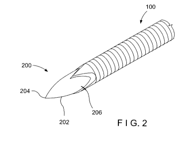
[0025] Fig. 2 shows an exemplary FNB device including the biopsy needle of
Fig. 1 with a stylet
having a sharp bullet-nose distal tip.
[0026] Fig. 3 shows a side view the FNB device of Fig. 2.
4
CA 03147452 2022-01-13
WO 2021/101686
PCT/US2020/057748
[0027] Fig. 4 shows an exemplary FNB device including the biopsy needle 100 of
Fig. 1 with a
hollow dilator 300 extending therethrough in accordance with the present
disclosure.
[0028] Fig. 5 shows a side-section view of the FNB device of Fig. 4.
[0029] Fig. 6 shows the FNB device of Fig. 4 with a puncturing wire extending
out the hollow
dilator.
[0030] Fig. 7 shows a side view of the FNB device of Fig. 4.
[0031] Fig. 8 shows an exemplary enclosure for attaching the dilator of Fig. 4
to the needle of
Fig. 1 and actuating the puncturing wire.
[0032] Fig. 9 shows an exemplary biopsy needle having a distal tip with a
modified Franseen
grind.
Detailed Description
[0033] The present disclosure may be further understood with reference to the
following
description and the appended drawings, wherein like elements are referred to
with the same
reference numerals. The exemplary embodiments describe fine needle biopsy
(FNB) needles
with improved puncture performance. In some embodiments, a sharpened
puncturing element
extending distally out the lumen of the needle is used to puncture the target
anatomical structure
prior to advancing the needle into and acquiring tissue from that anatomical
structure. The
sharpened puncturing element may have a further dilating effect to ease the
insertion of the
needle into the anatomy prior to tissue acquisition, as described below. It is
common practice in
fine needle biopsy to acquire tissue from the core of a lesion and not solely
from an exterior or
capsule area of the lesion. Thus, each of the devices has means for preventing
non-targeted
tissue from being acquired and for preventing the acquisition of tissue from
the target structure
5
CA 03147452 2022-01-13
WO 2021/101686
PCT/US2020/057748
until after the needle has been advanced into the target structure to a
desired puncture depth.
[0034] Fig. 1 shows a distal end of a biopsy needle 100 for use in an
endoscopic ultrasound fine
needle biopsy (EUS-FNB) procedure. The needle 100 includes a hollow shaft 102
having a
distal end 104 with a sharpened distal tip for puncturing and collecting
tissue from a target
anatomical structure (e.g., a lesion) when introduced into the target
anatomical structure via an
insertion device such as, for example, a flexible endoscope. The needle 100
is, in this
embodiment, formed from a cobalt-chromium (CoCr) alloy. CoCr has high strength
properties,
allowing needle tips fashioned from CoCr to resist bending during puncturing.
However, other
materials may be used for the needle 100, including, for example, nitinol or
stainless steel. For
example, nitinol may be used for larger gauge needles to avoid kinking. The
distal end 104 in
this embodiment has a Franseen grind, which results in a crown-like shape with
three pointed
tips separated from one another circumferentially by three ground notches.
However, other
shapes for the distal end 104 may be used, such as a beveled end, or any
number of pointed tips.
[0035] As shown in Figs. 2-3, an FNB device including the biopsy needle 100 of
Fig. 1 further
includes a stylet 200 having a bullet-nose distal end 202 with a sharp tissue
piercing distal tip
204 extending from a cylindrical shaft 206, the stylet 200 being sized and
shaped to extend
through the lumen of the hollow shaft 102 so that, in a distal-most position,
the tip 204 of the
stylet 200 extends distally out of the distal end 104 of the needle 100. The
distal end 202 has a
tapered cross-section with a side-section profile that may be considered
substantially ogival. In
other words, the "bullet-nose" of this embodiment has a side-section, as seen
in Fig. 3, formed by
two symmetrical segments of a curve (e.g., a circle) meeting at a point, i.e.,
the distal tip 204. In
this case, the radius of the needle 200 is smaller than a radius of each of
the curves defining the
symmetrical segments so that the tip 202 is less blunt (more tapered) than a
hemisphere having
the same diameter as the needle 200.
[0036] The curve of the distal end 202 gradually and smoothly transitions to
the cylindrical
shape of the shaft 206 at its proximal end. The radius of the curved segment
side-section may
vary. For instance, an ogival distal end 202 may have a profile matching a
shorter arc length of a
larger radius curve, or a longer arc length of a smaller radius circle. In
other embodiments, the
6
CA 03147452 2022-01-13
WO 2021/101686
PCT/US2020/057748
distal end 202 may not be strictly ogival, yet have a similar taper that, at
its proximal base,
remains tangent to the shaft 206 and curves radially inward but more closely
resembles a conical
taper approaching the distal tip 204. In still other embodiments, the segment
of the curve may be
elliptical.
[0037] The stylet 200 in this embodiment is formed from a superelastic nitinol
alloy permitting
the stylet/needle combination to navigate a tortuous path along the way to the
target tissue
through tight turning radii without plastic deformation. Other flexible alloys
may be used as well
as would be understood by those skilled in the art. The length of the stylet
200 is selected so
that, when inserted to a distal-most position within the needle 100, the
distal tip 204 of the
tapered distal end 202 extends a predetermined desired distance 208 (a
"setback") distally out of
the distal end 104 of the needle 100, as shown in Fig. 3. The FNB device may
be configured so
that the setback 208 corresponds to the distance from the distal tip 204 to
the flat of the shaft 206
of the stylet 200. In other words, the setback 208 may correspond to the
length of the bullet-nose
distal tip 202, which may vary based on the gauge of the needle 100. The
setback 208 is
dependent on the diameter of the needle 100 with a range of the setback 208
being approximately
0.08"- 0.6". In one embodiment, the setback 208 for the stylet 200 is ¨.1". In
alternate
embodiments, where a needle having a differently shaped tip (e.g., beveled
tip) is used, a similar
configuration for the setback 208 can be used. The stylet 200 is shaped so
that, even at shallow
approach angles, the distal tip 204 lodges in the target tissue. For example,
the distal tip 204 of
the stylet 200 may effectively puncture tissue at angles of 5 or more.
[0038] After puncturing the tissue, the stylet 200 may be further used to
dilate the target
capsule. The bullet nose shape of the distal end 202 of the stylet 200 (i.e.,
the gradual increase in
the diameter of the distal end 202 moving proximally from a minimum at the
distal tip 204
thereof) serves to spread the tissue as the stylet 200 is advanced distally
into the tissue so that the
needle 100 may be more smoothly inserted into the lesion behind the stylet
200. As noted
previously, some EUS-FNB procedures are used to acquire tissue from a core of
a lesion.
[0039] For these procedures, it is not desirable to begin acquiring tissue
until after the needle 100
has penetrated the lesion to a desired depth. To this end, the stylet shaft
206 is sized to minimize
7
CA 03147452 2022-01-13
WO 2021/101686
PCT/US2020/057748
a clearance (i.e. the annular gap) between the stylet 200 and the inner
diameter of the hollow
shaft 102, while remaining slidable therein, so that, as the stylet 200 is
maintained in its distal-
most position covering the distal opening of the hollow shaft 102, no tissue
enters the needle
during the puncturing of the lesion. After the needle 100 has been inserted
into the lesion to a
sufficient depth, the stylet 200 is withdrawn proximally from the needle 100
and the needle 100
is advanced further distally into the lesion to acquire a core tissue sample.
If multiple samples
are to be taken, the stylet 200 may again be inserted through the needle 100
and operated in a
similar manner. In addition, if any prong on the tip 104 of the needle 100 was
bent in any prior
tissue acquisitions, the stylet 200, being closely fitted with an inner
diameter (ID) of the needle
100, will straighten the bend(s) the next time it is advanced through the
distal end 104.
[0040] In another embodiment to be described below, a wire is advanced
distally out of the distal
end of a hollow dilator 300 to facilitate the initial puncturing of the target
tissue via a controlled
actuation from the needle handle. The wire may be spring-loaded or non-spring-
loaded, and be
actuated via a push button, slider, trigger, or some other actuator.
[0041] As shown in Figs. 4-7, an FNB device according to a further embodiment
includes a
biopsy needle 100 as described above in regard to Fig. 1 with a dilator 300
received in a lumen
of the needle 100. The dilator 300 includes a shaft 302 with a lumen extending
therethrough.
The dilator 300 extends to a rounded distal tip 304 with a distal opening
through which a
puncturing wire 306 may be advanced out of the dilator lumen to project
distally from a distal
end of the dilator 300. Figs. 4-5 show the dilator 300 with the puncturing
wire 306 retracted
within the lumen, i.e., in a pre-actuated state, while Figs. 6-7 show the
puncturing wire 306
extending distally out of the dilating tip 304, i.e., in an actuated state.
The dilator shaft 302 may
be formed, for example, from a superelastic material such as nitinol tubing or
a polymer
composite-sheathed coil or braid, while the dilating tip 304 may be a suitable
biocompatible
metal (such as nitinol), a polymer (e.g., PEEK, polycarbonate), glass, etc.,
as would be
understood by those skilled in the art. The material of the dilating tip 304
may be selected to
adhere well to the shaft 302 behind it.
[0042] The puncturing wire 306 may also be formed of a superelastic material
such as, for
8
CA 03147452 2022-01-13
WO 2021/101686
PCT/US2020/057748
example, nitinol. The diameter of the lumen of the dilator 300, and the
corresponding diameter
of the puncturing wire 306, are selected to be small enough so that the wire
306 is capable of
puncturing a target lesion even if the distal tip is not separately machined
to enhance a sharpness
of the distal tip. For example, the diameter may be .006". The distal tip of
the wire 306 may
also be sharpened to a point or have a wedged trocar tip. The setback 312
between the dilating
tip 304 and the distal end 104 of the needle may be configured similarly to
that described above
with respect to the stylet 200, i.e., may correspond to the distance from the
distal-most point of
the distal tip 304 of the dilator 300 to the flat of the dilator shaft 302.
The setback 314 between
the wire 306 and the dilating tip 304 may be a variable length.
[0043] For example, the wire 306 may have a shorter setback that functions
similarly to the
bullet-nose distal end 202 of the stylet 200 when the wire 306 is extended.
Considered this way,
the combination of the dilator 300 and the wire 306 provides an alternative to
the stylet 200 that
has a rounded, i.e. atraumatic, tip until the operating physician actuates the
wire 306. In another
__ embodiment, the wire 306 may have a longer setback relative to the dilating
tip 304. In this
embodiment, the wire 306 may be used to reach out and engage the lesion, even
at very shallow
approach angles. For example, the wire 306 may initially engage the lesion at
the shallow
approach angle and bend slightly to facilitate advancing the remainder of the
device (dilator 300,
needle 100) into the lesion.
[0044] The dilator 300, including the puncturing wire 306, extends from an
enclosure 308, as
shown in Fig. 8. The enclosure 308 may, for example, be threaded onto a luer
of a needle handle
and, in this embodiment, has a push button 310 for deploying the wire 306,
i.e., extending the
wire 306 from the pre-actuated state to the actuated state. However, actuators
other than the
push button 310 may be used. The deployment of the wire 306 may be rapid, or
it may be slow.
For example, when the wire 306 is in the pre-actuated state, the spring may be
compressed so
that, when the actuator is operated, the spring is released to drive the wire
306 rapidly distally
out of the distal end of the dilator 300 to penetrate target tissue. That is,
when it is desired to
penetrate a target anatomical structure, the distal end of the dilator 300 is
placed adjacent the
desired puncture site and the actuator is operated to drive the wire 306
distally out of the dilator
300 into the target tissue.
9
CA 03147452 2022-01-13
WO 2021/101686
PCT/US2020/057748
[0045] In an alternate embodiment, the wire 306 is advanced at any pace (fast
or slow), and the
tip of the wire 306 is then brought adjacent to the tissue for puncturing. The
user may then
advance the dilator 300 and the needle 100 distally over the wire 306 into the
target tissue mass.
Once the needle has been advanced into the target tissue mass to a desired
depth, the wire 306
and the dilator 300 may be withdrawn proximally (either retracted proximally
to a desired
distance within the needle 100 or fully withdrawn therefrom) and the needle
100 may be
advanced further into the target tissue mass to capture a tissue sample within
the needle 100.
[0046] As described above, during an EUS-FNB procedure, the enclosure 308 is
coupled to the
needle 100, as described above, and the dilating tip 304 is brought to a
desired position adjacent
to the target anatomy. The push button 310 is then actuated, extending the tip
of the puncturing
wire 306 distally out of the distal end of the dilating tip 304 so that the
wire 306 punctures the
target tissue. The user then advances dilator 300 and the needle 100 distally
into the target tissue
with the gradual increase in the diameter of the dilator 300 from a minimum at
its distal end,
gradually spreading open an opening formed by the wire 306 to facilitate a
smooth entry of the
needle 100 into the target tissue mass in a manner similar to that described
in regard to the
dilating stylet 200 with respect to Fig. 2. After the needle has been advanced
into the target
tissue mass to a desired depth, the dilator 300 is withdrawn proximally and
the needle 100 is
advanced distally to acquire the core tissue.
[0047] Fig. 9 shows a biopsy needle 400 having a distal tip 402 with modified
Franseen grind
that may be used in place of the needle 100 in the same manner described above
with either the
stylet 200 or a hollow dilator 300 and wire 306. Instead of the three equal-
sized puncturing
prongs shown with respect to the needle 100 shown in Fig. 1, the biopsy needle
400 has a prong
404 extending to a longer axial reach (i.e., extending further distally) than
the other two of the
prongs 406. The long prong 404 extends distally beyond distal ends of the
other prongs 406 to
allow the needle 400 to achieve an initial anchoring in a target tissue mass,
providing stability as
the rest of the tip 402 is advanced into the lesion. If desired, the needle
400 may perform the
initial puncturing and no stylet, or a blunt stylet may be used with the
needle 400. A blunt stylet
provides inner diameter support when the needle 400 takes a tortuous path, as
well as protecting
CA 03147452 2022-01-13
WO 2021/101686
PCT/US2020/057748
the tips of the Franseen grind during advancement of the needle 400. Further,
the blunt stylet
may prevent the distal tip 402 from damaging the endoscope as the needle 400
is advanced
distally theretluough. However, once the tip 402 has been advanced past the
distal end of the
endoscope, the blunt stylet may be withdrawn.
[0048] It will be appreciated by those skilled in the art that changes may be
made to the
embodiments described above without departing from the inventive concept
thereof It should
further be appreciated that structural features and methods associated with
one of the
embodiments can be incorporated into other embodiments. It is understood,
therefore, that this
invention is not limited to the particular embodiment disclosed, but rather
modifications are also
covered within the scope of the present invention as defined by the appended
claims.
Specifically, although this application describes various embodiments each
having different
features in various combinations, those skilled in the art will understand
that any of the features
of one embodiment may be combined with the features of the other embodiments
in any manner
not specifically disclaimed or which is not functionally or logically
inconsistent with the
operation of the device or the stated functions of the disclosed embodiments.
11